EP3982017A1 - Membrane assembly with reinforcing elements - Google Patents
Membrane assembly with reinforcing elements Download PDFInfo
- Publication number
- EP3982017A1 EP3982017A1 EP21193729.7A EP21193729A EP3982017A1 EP 3982017 A1 EP3982017 A1 EP 3982017A1 EP 21193729 A EP21193729 A EP 21193729A EP 3982017 A1 EP3982017 A1 EP 3982017A1
- Authority
- EP
- European Patent Office
- Prior art keywords
- membrane
- reinforcing elements
- arrangement according
- elements
- screw
- Prior art date
- Legal status (The legal status is an assumption and is not a legal conclusion. Google has not performed a legal analysis and makes no representation as to the accuracy of the status listed.)
- Pending
Links
Images



Classifications
-
- F—MECHANICAL ENGINEERING; LIGHTING; HEATING; WEAPONS; BLASTING
- F16—ENGINEERING ELEMENTS AND UNITS; GENERAL MEASURES FOR PRODUCING AND MAINTAINING EFFECTIVE FUNCTIONING OF MACHINES OR INSTALLATIONS; THERMAL INSULATION IN GENERAL
- F16K—VALVES; TAPS; COCKS; ACTUATING-FLOATS; DEVICES FOR VENTING OR AERATING
- F16K7/00—Diaphragm valves or cut-off apparatus, e.g. with a member deformed, but not moved bodily, to close the passage ; Pinch valves
- F16K7/12—Diaphragm valves or cut-off apparatus, e.g. with a member deformed, but not moved bodily, to close the passage ; Pinch valves with flat, dished, or bowl-shaped diaphragm
- F16K7/126—Diaphragm valves or cut-off apparatus, e.g. with a member deformed, but not moved bodily, to close the passage ; Pinch valves with flat, dished, or bowl-shaped diaphragm the seat being formed on a rib perpendicular to the fluid line
-
- F—MECHANICAL ENGINEERING; LIGHTING; HEATING; WEAPONS; BLASTING
- F16—ENGINEERING ELEMENTS AND UNITS; GENERAL MEASURES FOR PRODUCING AND MAINTAINING EFFECTIVE FUNCTIONING OF MACHINES OR INSTALLATIONS; THERMAL INSULATION IN GENERAL
- F16K—VALVES; TAPS; COCKS; ACTUATING-FLOATS; DEVICES FOR VENTING OR AERATING
- F16K7/00—Diaphragm valves or cut-off apparatus, e.g. with a member deformed, but not moved bodily, to close the passage ; Pinch valves
- F16K7/12—Diaphragm valves or cut-off apparatus, e.g. with a member deformed, but not moved bodily, to close the passage ; Pinch valves with flat, dished, or bowl-shaped diaphragm
Definitions
- the invention relates to a membrane arrangement with a membrane that separates spaces from one another in a sealing manner, the membrane comprising a membrane screw.
- Such membranes are used, for example, in membrane valves, membrane drives or membrane pumps.
- the diaphragm preferably seals the valve on a sealing web.
- a membrane valve is, for example, in DE 195 05 747 A1 described.
- the medium to be pumped is separated from the drive by the diaphragm.
- Diaphragm drives are used, for example, in the form of pneumatic drives in control valves. In this case, a membrane coupled to a spindle is preferably moved via compressed air.
- Diaphragm valves can be used to dose different fluids, such as gases, vapors or liquids. Diaphragm valves can be used, for example, to dose or distribute highly viscous or very strongly adhesive media. In the case of diaphragm valves, deposits and thus contamination are effectively prevented. Valves based on the membrane principle are metering fittings with the lowest dead space. In addition to the very low dead space volume, diaphragm valves are also designed to be drain-optimized, so that the medium can be removed without leaving any residue.
- diaphragm An important quality feature of a diaphragm is its mobility, i.e. the ability to perform a stroke perpendicular to the clamping surface (diaphragm surface), which can be mechanically driven.
- the resistance of the membrane is also important, especially when aggressive media are being pumped.
- Elastomers are mainly used as base materials for membranes, which can be reinforced with fabric inserts to achieve greater strength.
- Diaphragms with ethylene-propylene-diene rubber (EPDM) have proven themselves as elastomers.
- Ethylene-propylene-diene rubber (EPDM) is a terpolymeric elastomer (rubber) and is therefore a synthetic rubber. The material is characterized by high elasticity and good chemical resistance.
- the EP 3 323 583 A1 describes a method for producing a membrane and a membrane itself, in which a fabric insert and a membrane screw are integrated between two elastomer layers in a form-fitting manner.
- This membrane is manufactured using an injection molding process, which ensures consistent membrane quality.
- the object of the invention is to provide a membrane arrangement with a membrane that separates spaces from one another in a sealing manner and has a load-optimized connection between the actuating element and the membrane material.
- the membrane should Meet the requirements of vacuum operation or operation at negative pressure while preserving functional properties during the period of use.
- the membrane should be able to be produced in a way that is as inexpensive and particularly simple as possible and with as little material wastage as possible.
- the membrane should be characterized by a long service life.
- the membrane of the membrane arrangement has reinforcing elements.
- the reinforcement elements are preferably designed as webs which extend radially from the diaphragm screw to the edge of the diaphragm.
- the reinforcing elements form a one-piece structure with one another and with the membrane screw.
- This structure can be funnel-like with radially extending thin side arms.
- the structure is designed in the form of a spider's web, so that the radially extending webs are designed in one piece with rings.
- the number of rings can vary.
- the radial webs open into an outer ring. If the membrane is subjected to frequent switching cycles and vacuum operation, the structure of reinforcement elements can be reinforced with up to ten intermediate rings.
- the width of the radial webs is advantageously more than 1 mm, preferably more than 1.5 mm, in particular more than 2 mm, but less than 14 mm, preferably less than 12 mm, in particular less than 10 mm.
- the height of the webs and rings is more than 1 mm, preferably more than 1.5 mm, in particular more than 2 mm, but less than 10 mm, preferably less than 8 mm, in particular less than 6 mm.
- the cross section of the webs and rings can be round, triangular, rectangular or square.
- the one-piece structure of the reinforcing elements is encased by two layers of elastomer bonded together by vulcanization.
- the elastomer layers are preferably crosslinked with peroxides during the vulcanization.
- ethylene-propylene-diene rubber EPDM
- EPDM ethylene-propylene-diene rubber
- the vulcanization usually takes place with a sulfur content of 1.8 to 2.5% by weight and a temperature of approx. 120 to 160°C.
- the long-chain rubber molecules are crosslinked by peroxide bonds or sulfur bridges.
- the plastic properties of the rubber or the rubber mixture are lost and the substance is converted from the plastic to the elastic state by means of the vulcanization process.
- the elasticity of the rubber material depends on the number of peroxide bonds or sulfur bridges. The higher the degree of cross-linking, the harder the rubber. The number of bonds in turn depends on the amount of crosslinking substance added and the duration of the vulcanization.
- the radial webs have cutouts to produce a form-fitting connection with the EPDM layers.
- the recesses are preferably round, triangular, rectangular or square.
- the reinforcement rings and the outer ring can also have these recesses.
- the positive connection can be supported by the use of so-called adhesion promoters.
- the screw plate of the diaphragm screw can also have recesses and/or the radial webs can have grooves and/or the screw plate can have an adapted contour. Due to the optimization mentioned, a connection is created between the membrane material and the membrane screw with the one-piece structure made of reinforcement elements, which enables a long-lasting use of membrane valves in pipelines with negative pressure.
- the two reinforcing elements running over the sealing web of the valve have wedge-shaped elements to improve the sealing of the membrane.
- the cross section of the web is then preferably wedge-shaped toward the media surface.
- other cross-sections with a sealing function are conceivable, such as trapezoidal, funnel-shaped and triangular, etc Sealing of the valve necessary surface pressure increased.
- the otherwise usual increase in the membrane surface in the form of a sealing lip can be omitted because the increase in pressure is provided by the sealing elements of the web. This means that there is no need for a visible sealing lip to seal the valve.
- the two reinforcement elements also have these wedge-shaped elements for sealing perpendicular thereto, so that a cross-shaped structure of sealing elements is produced.
- a diaphragm with such a structure of reinforcement elements can therefore be installed in the valve in any orientation rotated by 90°. It therefore has protection against incorrect installation, since the positioning of the sealing lip over the sealing web, which is usually necessary, is no longer necessary.
- the outer ring can also have elements to increase sealing. This means that a visible sealing lip can also be dispensed with to seal the valve from the outside. A flat membrane is created without protruding sealing lips. This improves the cleaning properties of the membrane, which are important in sterile process engineering.
- the membrane arrangements according to the invention with the reinforcement elements are usually produced by means of compression molding.
- Compression molding is a manufacturing process for slightly curved or flat components.
- Thermoplastics or elastomers can also be processed.
- a molding compound which in this case comprises at least two elastomer layers and a one-piece structure made up of reinforcing elements including a membrane screw arranged in between, is introduced into a cavity which is heated.
- the cavity is then closed using a plunger.
- the pressure gives the molding compound the shape specified by the tool.
- the vulcanization process that then takes place under the influence of temperature gives the elastomer component its desired shape and rubber-elastic properties. After cooling, the finished component can be removed from the mold and processed further.
- the membrane arrangement with reinforcement elements can also be produced using the injection molding process.
- Injection molding is possible when the reinforcement elements also include the clamping frame, since this ensures the positioning of the reinforcement structure within the cavity.
- Injection molding is a process in which the respective elastomer material is liquefied (plasticized) with an injection molding machine and injected under pressure into a mold, the injection mold, in which the structure of reinforcing elements is already arranged.
- the elastomer material goes into the solid state through a cross-linking reaction. After opening the tool, the finished part, the membrane with integrated reinforcement elements, can be removed.
- the hollow space of the tool determines the shape and surface structure of the finished part.
- the reinforcing elements which are preferably designed as radial webs, are designed in one piece with the membrane screw.
- the one-piece construction of the membrane screw with the structure made of reinforcing elements withstands the enormous forces and effectively prevents the membrane screw from escaping from the membrane arrangement.
- the membrane advantageously has more than three, preferably more than four, in particular more than five, radial webs.
- the reinforcement elements are designed in the form of a spider's web, up to twelve radial webs can also be formed.
- the radial webs are branched in their radial extension.
- these branches have at least one arc, ideally two or three arcs. These arcs each describe an angle of more than 90°, preferably more than 120°, in particular more than 150°.
- This elastic configuration of the membrane arrangement is distinguished by an excellent longevity in the vacuum operation of the membrane valve.
- the reinforcement elements or the structure of the reinforcement elements and the clamping frame of the membrane arrangement are designed in one piece. Due to the one-piece construction from the membrane screw through the reinforcement elements to the clamping frame the membrane arrangement is designed to be particularly stable and protected against cracking during vacuum operation.
- the reinforcement elements have a concentric, circular extension from the membrane screw to an outer reinforcement ring.
- preferably four round webs run in circular paths from the inside to the outside.
- two to eight webs can run in spiral paths from the inside to the outside.
- a multi-threaded spiral shape of the webs is also in accordance with the invention.
- Such a membrane arrangement is characterized by excellent elasticity.
- the membrane screw and the reinforcement elements are made of a metallic material or preferably of a high-performance plastic, engineering plastic and/or engineering plastic.
- a material combination of a metallic material and a plastic is provided.
- a metallic component is cast in an injection molding process.
- the integral structure of the reinforcing members is made by primary molding.
- the device is cast from plastic, preferably from high-performance plastic, or is produced by means of additive processes, such as a build-up melt-layer process.
- High-performance plastics are a sub-group of thermoplastics that have improved in particular thanks to their temperature and chemical resistance characterize mechanical properties. They are also electrical insulators. Examples of these are polyether ketones, polyether ether ketones, polyphenylene sulfides, polybutylene terephthalate and polyamides.
- Diaphragm valve shown has a lower housing part 1, which includes connections 2, 3 and a weir 4.
- the weir 4 serves as a seat for the membrane 5.
- the membrane 5 is clamped between the lower housing part 1 and an upper housing part 7 with the aid of screws 6.
- the elements necessary for actuating the membrane 5 are integrated in the upper housing part 7, such as a drive 8, which is designed as a handwheel in the embodiment, and a spindle 9.
- a pressure piece 10 is attached on the spindle 9, a pressure piece 10 is attached.
- the pressure piece 10 is movably arranged in the upper housing part 7 and is guided by an inner wall of the upper housing part 7 .
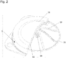
- FIG 2 shows a partially cut membrane 5 with reinforcement elements 13.
- the membrane 5 comprises a first layer 11, which is arranged on the medium side is. Furthermore, the membrane 5 includes a second layer 12, which forms the back of the membrane arrangement.
- the two layers 11 and 12 are made of an elastomer, in particular EPDM.
- the reinforcing elements 13 are arranged between the two EPDM layers 11, 12.
- the membrane 5 includes a pin-like element 14 which is designed as a membrane screw in the exemplary embodiment.
- pin-like element 14 may have a thread.
- the pin-like element 14 is designed as a membrane screw and has an external thread which is screwed into an internal thread which is designed in a pressure piece 10 .
- the membrane 5 as shown in FIG figure 2 it is a construction of two EPDM layers 11, 12 and a structure of reinforcing elements 13 arranged between them, which are connected to one another by vulcanization.
- the reinforcement elements 13 extend from the diaphragm screw 14 to an annular element 15, which in this exemplary embodiment is designed as a final reinforcement ring.
- the membrane screw 14, the reinforcement elements 13 and the ring-shaped element 15 are designed in one piece and can be manufactured, for example, using an injection molding process or a generative process from a high-performance plastic or metal material.
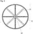
- FIG. 12 shows a top view of a one-piece structure formed from reinforcement elements 13.
- the reinforcing elements 13 extend from the diaphragm screw 14 to an annular element 15 which is this embodiment is designed as a final reinforcement ring.
- the structure of reinforcement elements 13 has more than three, preferably more than four, in particular more than five, reinforcement elements 13 .
- FIG. 12 shows a perspective view of a structure made up of reinforcement elements 13.
- FIG. In this exemplary embodiment, eight reinforcement elements 13 extend from the diaphragm screw 14 to an annular element 15. Some reinforcement rings 17 are arranged in between, so that a spider-web-like structure is formed. Recesses 16 are arranged on some reinforcement elements 13 in order to produce a positive connection with the EPDM layers, which are not shown in this figure. In other variants of the invention, these cutouts 16 can be arranged on only one reinforcement element 13 or on all reinforcement elements 13 . In an advantageous variant of the invention, the recesses 16 are also provided on the reinforcement rings 17 .
- the cross section of the reinforcement elements 13 and the reinforcement rings can be round, triangular, rectangular or square.
- the reinforcing elements 13 and the ring-shaped element 15 are rectangular and the reinforcing rings 17 are round.
- the reinforcing elements 13 have a width of more than 1 mm, preferably more than 1.5 mm, in particular more than 2 mm, but less than 14 mm, preferably less than 12 mm, in particular less than 10 mm.
- the height of the reinforcing elements 13 is more than 1 mm, preferably more than 1.5 mm, in particular more than 2 mm, but less than 10 mm, preferably less than 8 mm, in particular less than 6 mm.
- FIG. 13 shows a perspective view of a structure made up of reinforcement elements 13 integral with clamping frames 19.
- the structure formed from reinforcement elements corresponds to the structure of FIG figure 4 .
- the holes 18 are recessed for clamping in the membrane valve and for fixing with the screws, not shown here.
- figure 6 shows a top view of a structure formed from reinforcement elements 13 with branches 20 and bends 21.
- eight reinforcement elements 13 extend from the membrane screw 14 to an annular element 15.
- the reinforcement elements 13 have branches 20, so that from a reinforcement element 13 two branched reinforcement elements 22 arise.
- the branched reinforcement elements in the in figure 6 shown embodiment two sheets 21 on.
- a reinforcement element 13 extends from the membrane screw 14 , branches into two branched reinforcement elements 22 , which are looped back through the arches 21 until they open into an outer ring-shaped element 15 .
- the structure formed in this way which is then embedded between two EPDM layers of the membrane, is characterized by a particularly elastic behavior.
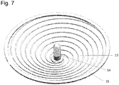
- FIG. 12 shows a perspective view of a structure made up of reinforcement elements 13.
- FIG. 12 In this exemplary embodiment, four reinforcing elements 13 preferably draw spiral-shaped circles, starting from the membrane screw 14, up to an outer ring-shaped element 15.
- 2 to 8 reinforcing elements can also form a spiral-shaped structure.
- the structure shown is made in one piece from a high-performance plastic.
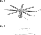
- figure 8 shows a perspective view of the one-piece structure made of reinforcement elements 13 with wedge-shaped sealing elements 23.
- the reinforcement elements 13 extend from the diaphragm screw 14 to an annular element, not shown.
- the structure of reinforcement elements 13 has more than three, preferably more than four, in particular more than five, reinforcement elements 13 .
- wedge-shaped elements 23 are arranged on four reinforcing elements 13 running over the sealing web of the valve. As a result, the surface pressure of the membrane 5 required to seal the valve is increased. The otherwise usual increase in the membrane surface in the form of a sealing lip can be omitted.
- the reinforcing elements 13 offset by 90° have the wedge-shaped elements for sealing, so that a cross-shaped structure of sealing elements is created.
- a membrane 5 with such a reinforcement element structure can therefore be installed in the valve in any orientation rotated by 90°. The usual necessary positioning of the sealing lip over the sealing ridge is omitted since this membrane 5 cannot be installed incorrectly.
- figure 9 shows a sectional view of a reinforcement element 13.
- a wedge-shaped element 23 for sealing the membrane 5 and as a replacement sealing lip is arranged on a broad side of the reinforcement element 13.
Landscapes
- Engineering & Computer Science (AREA)
- General Engineering & Computer Science (AREA)
- Mechanical Engineering (AREA)
- Reciprocating Pumps (AREA)
- Diaphragms And Bellows (AREA)
Abstract
Membrananordnung mit einer Membran (5), die Räume voneinander dichtend trennt. Die Membran (5) umfasst eine Membranschraube (14). Die Membran (5) weist Verstärkungselemente (13) auf.

Description
Die Erfindung betrifft eine Membrananordnung mit einer Membran, die Räume voneinander dichtend trennt, wobei die Membran eine Membranschraube umfasst.The invention relates to a membrane arrangement with a membrane that separates spaces from one another in a sealing manner, the membrane comprising a membrane screw.
Solche Membranen werden beispielsweise in Membranventilen, Membranantrieben oder Membranpumpen eingesetzt. Bei Membranventilen dichtet die Membran das Ventil vorzugsweise auf einem Dichtsteg ab. Ein solches Membranventil wird beispielsweise in der
Membranventile können zur Dosierung von unterschiedlichen Fluiden eingesetzt werden, beispielsweise von Gasen, Dämpfen oder Flüssigkeiten. Beispielgebend können Membranventile eingesetzt werden, um hochviskose bzw. sehr stark haftfähige Medien zu dosieren bzw. zu verteilen. Bei Membranventilen wird dabei wirksam eine Ablagerung und somit auch eine Kontamination verhindert. Ventile auf Basis des Membranprinzips sind die totraumärmsten Dosierarmaturen. Neben dem sehr geringen Totraumvolumen sind Membranventile zudem entleerungsoptimiert konstruiert, sodass eine rückstandsfreie Entfernung des Mediums ermöglicht wird.Diaphragm valves can be used to dose different fluids, such as gases, vapors or liquids. Diaphragm valves can be used, for example, to dose or distribute highly viscous or very strongly adhesive media. In the case of diaphragm valves, deposits and thus contamination are effectively prevented. Valves based on the membrane principle are metering fittings with the lowest dead space. In addition to the very low dead space volume, diaphragm valves are also designed to be drain-optimized, so that the medium can be removed without leaving any residue.
Dies ist insbesondere bei pharmazeutischen Anlagen und Fertigungsprozessen von großer Bedeutung, da diese den hohen Ansprüchen einer strengen Validierung unterliegen, mit dem Ziel, eine gleichbleibende und reproduzierbare Qualität zu gewährleisten. Aus diesen Ansprüchen resultiert die Notwendigkeit, verschiedene Prozesse innerhalb einer Anlage fahren zu können. Neben dem eigentlichen Produktionsprozess sind dies in der Regel die Reinigung, Desinfektion und Sterilisation der Anlage. Membranventile haben sich aufgrund ihrer vorteilhaften Konstruktionsmerkmale als bevorzugte Armatur in der sterilen Prozesstechnik etabliert.This is particularly important for pharmaceutical systems and manufacturing processes, as these are subject to the high demands of strict validation with the aim of ensuring consistent and reproducible quality. These demands result in the need to be able to run different processes within a system. In addition to the actual production process, these are usually the cleaning, disinfection and sterilization of the system. Diaphragm valves have established themselves as the preferred fitting in sterile process technology due to their advantageous design features.
Ein wichtiges Qualitätsmerkmal einer Membran ist deren Beweglichkeit, das heißt die Fähigkeit senkrecht zur Einspannfläche (Membranfläche) einen Hub auszuführen, der mechanisch angetrieben bedingt sein kann. Weiterhin ist die Beständigkeit der Membran von Bedeutung, insbesondere wenn aggressive Medien gefördert werden.An important quality feature of a diaphragm is its mobility, i.e. the ability to perform a stroke perpendicular to the clamping surface (diaphragm surface), which can be mechanically driven. The resistance of the membrane is also important, especially when aggressive media are being pumped.
Die Bewegungsfähigkeit und Beständigkeit einer Membran hängt im Wesentlichen vom Werkstoff ab, aus dem die Membran besteht. Als Grundwerkstoffe für Membranen werden hauptsächlich Elastomere verwendet, die zur Erzielung einer höheren Festigkeit mit Gewebeeinlagen verstärkt werden können. Als Elastomere haben sich Membranen mit Ethylen-Propylen-Dien-Kautschuk (EPDM) bewährt. Bei Ethylen-Propylen-Dien-Kautschuk (EPDM) handelt es sich um terpolymere Elastomere (Gummi) und somit um synthetische Kautschuke. Das Material zeichnet sich durch eine hohe Elastizität und gute chemische Beständigkeit aus.The mobility and stability of a membrane essentially depends on the material from which the membrane is made. Elastomers are mainly used as base materials for membranes, which can be reinforced with fabric inserts to achieve greater strength. Diaphragms with ethylene-propylene-diene rubber (EPDM) have proven themselves as elastomers. Ethylene-propylene-diene rubber (EPDM) is a terpolymeric elastomer (rubber) and is therefore a synthetic rubber. The material is characterized by high elasticity and good chemical resistance.
In der
Die
Die Beständigkeit der Membran beim Einsatz von Membranventilen im Vakuumbetrieb bzw. beim Betrieb bei Unterdruck ist trotz der Gewebeverstärkung begrenzt. Nach überschaubarer Einsatzzeit können sich im Bereich um die Membranschraube Risse bilden, bis die Membran nach kurzer Zeit von der Membranschraube abreist. Im ungünstigsten Fall kann es zu einem Medienaustritt kommen. Die schadhafte Membran muss ersetzt werden, was zu Maschinen- und Anlagenstillständen mit entsprechenden ökonomischen Einbußen führt.The resistance of the diaphragm when using diaphragm valves in vacuum operation or when operating under negative pressure is limited despite the fabric reinforcement. After a reasonable period of use, cracks can form in the area around the membrane screw until the membrane tears off the membrane screw after a short time. In the worst case, there may be a media exit. The damaged membrane has to be replaced, which leads to machine and system downtimes with corresponding economic losses.
Aufgabe der Erfindung ist es, eine Membrananordnung mit einer Membran bereitzustellen, die Räume voneinander dichtend trennt und dabei eine belastungsoptimierte Verbindung zwischen Betätigungselement und Membranwerkstoff aufweist. Darüber hinaus soll die Membran den Anforderungen des Vakuumbetriebes bzw. des Betriebs bei Unterdruck gerecht werden und dabei funktionale Eigenschaften während der Einsatzzeit bewahren. Die Membran soll sich auf möglichst preiswerte sowie besonders einfache Weise und mit einem möglichst geringen Materialausschuss herstellen lassen. Dabei soll sich die Membran durch eine hohe Lebensdauer auszeichnen.The object of the invention is to provide a membrane arrangement with a membrane that separates spaces from one another in a sealing manner and has a load-optimized connection between the actuating element and the membrane material. In addition, the membrane should Meet the requirements of vacuum operation or operation at negative pressure while preserving functional properties during the period of use. The membrane should be able to be produced in a way that is as inexpensive and particularly simple as possible and with as little material wastage as possible. The membrane should be characterized by a long service life.
Diese Aufgabe wird erfindungsgemäß durch eine Membrananordnung gemäß den Merkmalen des Anspruchs 1 gelöst. Bevorzugte Varianten sind den Unteransprüchen, der Beschreibung und den Figuren zu entnehmen.According to the invention, this object is achieved by a membrane arrangement according to the features of
Erfindungsgemäß weist die Membran der Membrananordnung Verstärkungselemente auf. Vorzugsweise sind die Verstärkungselemente als Stege ausgebildet, die sich radial von der Membranschraube an den Membranrand erstrecken.According to the invention, the membrane of the membrane arrangement has reinforcing elements. The reinforcement elements are preferably designed as webs which extend radially from the diaphragm screw to the edge of the diaphragm.
Idealerweise bilden die Verstärkungselemente untereinander und mit der Membranschraube eine einstückige Struktur aus. Diese Struktur kann mit radial verlaufenden, dünnen Seitenarmen trichterähnlich sein. In einer vorteilhaften Ausgestaltung der Erfindung ist die Struktur spinnennetzförmig ausgestaltet, so dass die radial verlaufenden Stege mit Ringen einstückig ausgebildet sind. Dabei kann die Anzahl der Ringe variieren. In einer einfachen Variante münden die radialen Stege in einem äußeren Ring. Wird die Membran häufigen Schaltzyklen und Vakuumbetrieb unterworfen, kann die Struktur aus Verstärkungselementen mit bis zu zehn Zwischenringen verstärkt sein.Ideally, the reinforcing elements form a one-piece structure with one another and with the membrane screw. This structure can be funnel-like with radially extending thin side arms. In an advantageous embodiment of the invention, the structure is designed in the form of a spider's web, so that the radially extending webs are designed in one piece with rings. The number of rings can vary. In a simple variant, the radial webs open into an outer ring. If the membrane is subjected to frequent switching cycles and vacuum operation, the structure of reinforcement elements can be reinforced with up to ten intermediate rings.
Vorteilhafterweise beträgt die Breite der radialen Stege mehr als 1 mm, vorzugsweise mehr als 1,5 mm, insbesondere mehr als 2 mm, und aber weniger als 14 mm, vorzugsweise weniger als 12 mm, insbesondere weniger als 10 mm. Erfindungsgemäß beträgt die Höhe der Stege und Ringe mehr als 1 mm, vorzugsweise mehr als 1,5 mm, insbesondere mehr als 2 mm, und aber weniger als 10 mm, vorzugsweise weniger als 8 mm, insbesondere weniger als 6 mm. Dabei kann der Querschnitt der Stege und Ringe rund, dreieckig, rechteckig oder quadratisch ausgebildet sein.The width of the radial webs is advantageously more than 1 mm, preferably more than 1.5 mm, in particular more than 2 mm, but less than 14 mm, preferably less than 12 mm, in particular less than 10 mm. According to the invention, the height of the webs and rings is more than 1 mm, preferably more than 1.5 mm, in particular more than 2 mm, but less than 10 mm, preferably less than 8 mm, in particular less than 6 mm. The cross section of the webs and rings can be round, triangular, rectangular or square.
Gemäß der Erfindung ist die einstückige Struktur der Verstärkungselemente von zwei Lagen eines Elastomers umschlossen, die mittels Vulkanisation miteinander verbunden sind. Vorzugsweise werden bei der Vulkanisation die Elastomer-Lagen mit Peroxiden vernetzt. Alternativ kann Ethylen-Propylen-Dien-Kautschuk (EPDM) ggf. auch Schwefel bzw. aus Schwefel verwertete Stoffe, wie zum Beispiel Schwefeldifluorid, Katalysatoren bzw. Zinkoxid oder Fettsäuren enthalten. Die Vulkanisation erfolgt meist mit einem Schwefelanteil von 1,8 bis 2,5 Gew.-% und einer Temperatur von ca. 120 bis 160°C. Dabei werden die langkettigen Kautschukmoleküle durch Peroxidbindungen oder Schwefelbrücken vernetzt. Hierdurch gehen die plastischen Eigenschaften des Kautschuks bzw. der Kautschukmischung verloren und der Stoff wird mittels des Verfahrens der Vulkanisation vom plastischen in den elastischen Zustand überführt. In der Regel ist die Elastizität des Gummiwerkstoffs abhängig von der Anzahl der Peroxidbindungen oder Schwefelbrücken. Je höher der Vernetzungsgrad, desto härter ist der Gummi. Die Anzahl der Bindungen ist wiederum abhängig von der zugesetzten Menge des vernetzenden Stoffes und der Dauer der Vulkanisation.According to the invention, the one-piece structure of the reinforcing elements is encased by two layers of elastomer bonded together by vulcanization. The elastomer layers are preferably crosslinked with peroxides during the vulcanization. Alternatively, ethylene-propylene-diene rubber (EPDM) may also contain sulfur or substances made from sulfur, such as sulfur difluoride, catalysts or zinc oxide or fatty acids. The vulcanization usually takes place with a sulfur content of 1.8 to 2.5% by weight and a temperature of approx. 120 to 160°C. The long-chain rubber molecules are crosslinked by peroxide bonds or sulfur bridges. As a result, the plastic properties of the rubber or the rubber mixture are lost and the substance is converted from the plastic to the elastic state by means of the vulcanization process. As a rule, the elasticity of the rubber material depends on the number of peroxide bonds or sulfur bridges. The higher the degree of cross-linking, the harder the rubber. The number of bonds in turn depends on the amount of crosslinking substance added and the duration of the vulcanization.
In einer vorteilhaften Variante weisen die radialen Stege Aussparungen zur Erzeugung einer formschlüssigen Verbindung mit den EPDM-Lagen auf. Vorzugsweise sind die Aussparungen rund, dreieckig, rechteckig oder quadratisch. In einer alternativen Variante der Erfindung können auch die Verstärkungsringe und der äußere Ring diese Aussparungen aufweisen. Die formschlüssige Verbindung kann durch den Einsatz sogenannter Haftvermittler unterstützt werden.In an advantageous variant, the radial webs have cutouts to produce a form-fitting connection with the EPDM layers. The recesses are preferably round, triangular, rectangular or square. In an alternative variant of the invention, the reinforcement rings and the outer ring can also have these recesses. The positive connection can be supported by the use of so-called adhesion promoters.
Zur Erzielung einer belastungsoptimierten formschlüssigen Verbindung zwischen Elastomer-Werkstoff und Verstärkungselementen kann auch der Schraubenteller der Membranschaube Aussparungen aufweisen und/oder die radialen Stege können Rillen aufweisen und/oder der Schraubenteller kann eine angepasste Kontur aufweisen. Aufgrund der genannten Optimierungen wird eine Verbindung zwischen dem Membranwerkstoff und der Membranschraube mit der einstückig ausgebildeten Struktur aus Verstärkungselementen erzeugt, die einen langlebigen Einsatz von Membranventilen in Rohrleitungen mit Unterdruck ermöglicht.To achieve a load-optimized positive connection between the elastomeric material and the reinforcement elements, the screw plate of the diaphragm screw can also have recesses and/or the radial webs can have grooves and/or the screw plate can have an adapted contour. Due to the optimization mentioned, a connection is created between the membrane material and the membrane screw with the one-piece structure made of reinforcement elements, which enables a long-lasting use of membrane valves in pipelines with negative pressure.
In einer vorteilhaften Variante weisen die zwei über dem Dichtsteg des Ventils verlaufenden Verstärkungselemente keilförmige Elemente zur Verbesserung der Abdichtung der Membran auf. Der Querschnitt des Stegs ist dann zur Medienoberfläche hin vorzugsweise keilförmig ausgebildet. Darüber hinaus sind auch weitere Querschnitte mit dichtender Funktion denkbar, wie beispielsweise trapezförmig, trichterförmig und dreiecksförmig etc. Dadurch wird die zur Abdichtung des Ventils notwendige Flächenpressung erhöht. Die sonst übliche Erhöhung der Membranoberfläche in Form einer Dichtlippe kann dadurch entfallen, da die Erhöhung der Pressung durch die Dichtelemente des Stegs erfolgt. Somit kann zur Abdichtung des Ventils auf eine sichtbare Dichtlippe verzichtet werden.In an advantageous variant, the two reinforcing elements running over the sealing web of the valve have wedge-shaped elements to improve the sealing of the membrane. The cross section of the web is then preferably wedge-shaped toward the media surface. In addition, other cross-sections with a sealing function are conceivable, such as trapezoidal, funnel-shaped and triangular, etc Sealing of the valve necessary surface pressure increased. The otherwise usual increase in the membrane surface in the form of a sealing lip can be omitted because the increase in pressure is provided by the sealing elements of the web. This means that there is no need for a visible sealing lip to seal the valve.
In einer besonders vorteilhaften Variante weisen auch die beiden Verstärkungselemente senkrecht dazu diese keilförmigen Elemente zur Abdichtung auf, sodass eine kreuzförmige Struktur aus Dichtelementen entsteht. Eine Membran mit einer solchen Struktur an Verstärkungselementen kann demnach in beliebiger Orientierung um 90° verdreht im Ventil eingebaut werden. Sie besitzt somit einen Schutz vor Falscheinbau, da die üblicherweise notwendige Positionierung der Dichtlippe über dem Dichtsteg entfällt.In a particularly advantageous variant, the two reinforcement elements also have these wedge-shaped elements for sealing perpendicular thereto, so that a cross-shaped structure of sealing elements is produced. A diaphragm with such a structure of reinforcement elements can therefore be installed in the valve in any orientation rotated by 90°. It therefore has protection against incorrect installation, since the positioning of the sealing lip over the sealing web, which is usually necessary, is no longer necessary.
Darüber hinaus kann auch der äußere Ring über Elemente zur Erhöhung der Abdichtung verfügen. Somit kann zur Abdichtung des Ventils nach außen ebenfalls auf eine sichtbare Dichtlippe verzichtet werden. Es entsteht eine flache Membran ohne vorstehende Dichtlippen. Dies verbessert die in der sterilen Verfahrenstechnik wichtige Reinigungseigenschaft der Membran.In addition, the outer ring can also have elements to increase sealing. This means that a visible sealing lip can also be dispensed with to seal the valve from the outside. A flat membrane is created without protruding sealing lips. This improves the cleaning properties of the membrane, which are important in sterile process engineering.
Üblicherweise werden die erfindungsgemäßen Membrananordnungen mit den Verstärkungselementen mittels Formpressen (Compression Moulding) hergestellt. Das Formpressen ist ein Herstellungsverfahren für leicht gewölbte oder flache Bauteile. Dabei können auch thermoplastische Kunststoffe bzw. Elastomere verarbeitet werden. Zu Beginn des Verfahrens wird eine Formmasse, die in diesem Fall mindestens zwei Elastomer-Lagen und eine dazwischen angeordnete, einstückige Struktur aus Verstärkungselementen inklusive Membranschraube umfasst, in eine Kavität eingebracht, welche aufgeheizt wird. Anschließend wird die Kavität unter Einsatz eines Druckkolbens geschlossen. Durch den Druck erlangt die Formmasse die vom Werkzeug vorgegebene Form. Der anschließend unter Temperatureinwirkung stattfindende Vulkanisationsprozess verleiht dem Elastomerbauteil seine gewünschte Form und die gummielastischen Eigenschaften. Nach dem Abkühlen kann das fertige Bauteil aus dem Formwerkzeug entnommen und nach- bzw. weiterverarbeitet werden.The membrane arrangements according to the invention with the reinforcement elements are usually produced by means of compression molding. Compression molding is a manufacturing process for slightly curved or flat components. Thermoplastics or elastomers can also be processed. At the beginning of the process, a molding compound which in this case comprises at least two elastomer layers and a one-piece structure made up of reinforcing elements including a membrane screw arranged in between, is introduced into a cavity which is heated. The cavity is then closed using a plunger. The pressure gives the molding compound the shape specified by the tool. The vulcanization process that then takes place under the influence of temperature gives the elastomer component its desired shape and rubber-elastic properties. After cooling, the finished component can be removed from the mold and processed further.
In einer vorteilhaften Variante kann die Membrananordnung mit Verstärkungselementen auch über das Spritzgieß-Verfahren hergestellt werden. Das Spritzgießen ist dann möglich, wenn die Verstärkungselemente auch den Einspannrahmen umfassen, da somit die Positionierung der Verstärkungsstruktur innerhalb der Kavität gewährleistet ist. Das Spritzgießen (Injection-Moulding) ist ein Verfahren, bei dem mit einer Spritzgießmaschine der jeweilige Elastomer-Werkstoff verflüssigt (plastifiziert) wird und in eine Form, dem Spritzgusswerkzeug unter Druck eingespritzt wird, in dem die Struktur aus Verstärkungselementen bereits angeordnet ist. Im Werkzeug geht der Elastomer-Werkstoff durch eine Vernetzungsreaktion in den festen Zustand über. Nach dem Öffnen des Werkzeugs kann das Fertigteil, die Membran mit integrierten Verstärkungselementen, entnommen werden. Der Hohlraum, die Kavität, des Werkzeugs bestimmt dabei die Form und die Oberflächenstruktur des fertigen Teiles.In an advantageous variant, the membrane arrangement with reinforcement elements can also be produced using the injection molding process. Injection molding is possible when the reinforcement elements also include the clamping frame, since this ensures the positioning of the reinforcement structure within the cavity. Injection molding is a process in which the respective elastomer material is liquefied (plasticized) with an injection molding machine and injected under pressure into a mold, the injection mold, in which the structure of reinforcing elements is already arranged. In the tool, the elastomer material goes into the solid state through a cross-linking reaction. After opening the tool, the finished part, the membrane with integrated reinforcement elements, can be removed. The hollow space of the tool determines the shape and surface structure of the finished part.
Gemäß der Erfindung sind die Verstärkungselemente, die vorzugsweise als radiale Stege ausgeführt sind, mit der Membranschraube einstückig ausgebildet. Insbesondere beim Vakuumbetrieb der Membran hält die einstückige Ausbildung der Membranschraube mit der Struktur aus Verstärkungselementen den enormen Kräften stand und verhindert wirksam ein Ausreisen der Membranschraube aus der Membrananordnung.According to the invention, the reinforcing elements, which are preferably designed as radial webs, are designed in one piece with the membrane screw. In particular when the membrane is operated under vacuum, the one-piece construction of the membrane screw with the structure made of reinforcing elements withstands the enormous forces and effectively prevents the membrane screw from escaping from the membrane arrangement.
Vorteilhafterweise weist die Membran mehr als drei, vorzugsweise mehr als vier, insbesondere mehr als fünf, radiale Stege auf. Bei der Ausgestaltung der Verstärkungselemente in Form eines Spinnennetzes können auch bis zu zwölf radiale Stege ausgebildet sein.The membrane advantageously has more than three, preferably more than four, in particular more than five, radial webs. When the reinforcement elements are designed in the form of a spider's web, up to twelve radial webs can also be formed.
In einer besonders elastischen Variante der Erfindung sind die radialen Stege in ihrer radialen Erstreckung verzweigt. Vorzugsweise weisen diese Verzweigungen mindestens einen Bogen, idealerweise zwei oder drei Bögen auf. Diese Bögen beschreiben jeweils einen Winkel von mehr als 90 °, vorzugsweise mehr als 120 °, insbesondere mehr als 150 °. Diese elastische Ausgestaltung der Membrananordnung zeichnet sich durch eine hervorragende Langlebigkeit im Vakuumbetrieb des Membranventils aus.In a particularly elastic variant of the invention, the radial webs are branched in their radial extension. Preferably these branches have at least one arc, ideally two or three arcs. These arcs each describe an angle of more than 90°, preferably more than 120°, in particular more than 150°. This elastic configuration of the membrane arrangement is distinguished by an excellent longevity in the vacuum operation of the membrane valve.
In einer weiteren Variante der Erfindung sind die Verstärkungselemente bzw. die Struktur der Verstärkungselemente und der Einspannrahmen der Membrananordnung einstückig ausgebildet. Aufgrund der Einstückigkeit von der Membranschraube über die Verstärkungselemente bis zum Einspannrahmen ist die Membrananordnung besonders stabil ausgestaltet und gegen Rissbildung während des Vakuumbetriebs geschützt.In a further variant of the invention, the reinforcement elements or the structure of the reinforcement elements and the clamping frame of the membrane arrangement are designed in one piece. Due to the one-piece construction from the membrane screw through the reinforcement elements to the clamping frame the membrane arrangement is designed to be particularly stable and protected against cracking during vacuum operation.
In einer alternativen Ausgestaltung der Erfindung weisen die Verstärkungselemente eine konzentrische, kreisförmige Erstreckung von der Membranschraube bis zu einem äußeren Verstärkungsring auf. Dabei verlaufen vorzugsweise vier runde Stege in kreisförmigen Bahnen von innen nach außen. In einer alternativen Variante können zwei bis acht Stege in spiralförmigen Bahnen von innen nach außen verlaufen. Weiterhin ist auch eine mehrgängige Spiralform der Stege erfindungsgemäß. Eine solche Membrananordnung zeichnet sich durch eine hervorragende Elastizität aus.In an alternative embodiment of the invention, the reinforcement elements have a concentric, circular extension from the membrane screw to an outer reinforcement ring. In this case, preferably four round webs run in circular paths from the inside to the outside. In an alternative variant, two to eight webs can run in spiral paths from the inside to the outside. Furthermore, a multi-threaded spiral shape of the webs is also in accordance with the invention. Such a membrane arrangement is characterized by excellent elasticity.
Vorteilhafterweise sind die Membranschraube und die Verstärkungselemente aus einem metallischen Werkstoff oder vorzugsweise aus einem Hochleistungskunststoff, technischem Kunststoff und/oder Konstruktionskunststoff gebildet. In einer alternativen Variante der Erfindung ist eine Werkstoffkombination aus einem metallischen Werkstoff und einem Kunststoff vorgesehen. Dabei wird ein metallisches Bauteil in einem Spritzgussverfahren ausgegossen. Gemäß der Erfindung wird die einstückige Struktur der Verstärkungselemente durch Urformen angefertigt. Dazu wird die Vorrichtung aus Kunststoff, vorzugsweise aus Hochleistungskunststoff, gegossen oder mittels generativen Verfahren, wie beispielsweise einem aufbauenden Schmelzschicht-Verfahren, hergestellt. Hochleistungskunststoffe sind eine Untergruppe der thermoplastischen Kunststoffe, die sich besonders durch ihre Temperatur- und Chemikalienbeständigkeit bei gleichzeitig verbesserten mechanischen Eigenschaften auszeichnen. Des Weiteren sind sie elektrische Nichtleiter. Beispiele hierfür sind Polyetherketone, Polyetheretherketone, Polyphenylensulfide, Polybutylenterephthalat und Polyamide.Advantageously, the membrane screw and the reinforcement elements are made of a metallic material or preferably of a high-performance plastic, engineering plastic and/or engineering plastic. In an alternative variant of the invention, a material combination of a metallic material and a plastic is provided. A metallic component is cast in an injection molding process. According to the invention, the integral structure of the reinforcing members is made by primary molding. For this purpose, the device is cast from plastic, preferably from high-performance plastic, or is produced by means of additive processes, such as a build-up melt-layer process. High-performance plastics are a sub-group of thermoplastics that have improved in particular thanks to their temperature and chemical resistance characterize mechanical properties. They are also electrical insulators. Examples of these are polyether ketones, polyether ether ketones, polyphenylene sulfides, polybutylene terephthalate and polyamides.
Weitere Merkmale und Vorteile der Erfindung ergeben sich aus der Beschreibung von Ausführungsbeispielen anhand von Zeichnungen und aus den Zeichnungen selbst.Further features and advantages of the invention result from the description of exemplary embodiments based on drawings and from the drawings themselves.
Dabei zeigt:
Figur 1- eine Schnittdarstellung eines Membranventils,
Figur 2- eine teilgeschnittene Membran mit Verstärkungselementen,
Figur 3- eine Draufsicht auf eine aus Verstärkungselementen gebildete Struktur,
Figur 4- eine perspektivische Ansicht einer aus Verstärkungselementen gebildeten Struktur,
Figur 5- eine perspektivische Ansicht einer aus Verstärkungselementen gebildeten Struktur mit Einspannrahmen,
Figur 6- eine Draufsicht auf eine aus Verstärkungselementen gebildete Struktur mit Verzweigungen und Bögen,
Figur 7- eine perspektivische Ansicht einer aus Verstärkungselementen gebildeten Struktur,
Figur 8- eine perspektivische Ansicht der Struktur aus Verstärkungselementen mit keilförmigen Dichtelementen,
Figur 9- eine Schnittdarstellung eines Verstärkungselements.
- figure 1
- a sectional view of a diaphragm valve,
- figure 2
- a partially cut membrane with reinforcement elements,
- figure 3
- a plan view of a structure formed from reinforcement elements,
- figure 4
- a perspective view of a structure formed from reinforcement elements,
- figure 5
- a perspective view of a structure formed from reinforcement elements with a clamping frame,
- figure 6
- a plan view of a structure formed from reinforcement elements with branches and arches,
- figure 7
- a perspective view of a structure formed from reinforcement elements,
- figure 8
- a perspective view of the structure of reinforcement elements with wedge-shaped sealing elements,
- figure 9
- a sectional view of a reinforcement element.
Das in
Das in
Claims (17)
Priority Applications (1)
| Application Number | Priority Date | Filing Date | Title |
|---|---|---|---|
| EP22194782.3A EP4119819A1 (en) | 2020-10-06 | 2021-08-30 | Membrane assembly with reinforcing elements |
Applications Claiming Priority (1)
| Application Number | Priority Date | Filing Date | Title |
|---|---|---|---|
| DE102020126105.5A DE102020126105A1 (en) | 2020-10-06 | 2020-10-06 | Diaphragm assembly with reinforcement elements |
Related Child Applications (1)
| Application Number | Title | Priority Date | Filing Date |
|---|---|---|---|
| EP22194782.3A Division EP4119819A1 (en) | 2020-10-06 | 2021-08-30 | Membrane assembly with reinforcing elements |
Publications (1)
| Publication Number | Publication Date |
|---|---|
| EP3982017A1 true EP3982017A1 (en) | 2022-04-13 |
Family
ID=77543360
Family Applications (2)
| Application Number | Title | Priority Date | Filing Date |
|---|---|---|---|
| EP21193729.7A Pending EP3982017A1 (en) | 2020-10-06 | 2021-08-30 | Membrane assembly with reinforcing elements |
| EP22194782.3A Pending EP4119819A1 (en) | 2020-10-06 | 2021-08-30 | Membrane assembly with reinforcing elements |
Family Applications After (1)
| Application Number | Title | Priority Date | Filing Date |
|---|---|---|---|
| EP22194782.3A Pending EP4119819A1 (en) | 2020-10-06 | 2021-08-30 | Membrane assembly with reinforcing elements |
Country Status (2)
| Country | Link |
|---|---|
| EP (2) | EP3982017A1 (en) |
| DE (1) | DE102020126105A1 (en) |
Families Citing this family (1)
| Publication number | Priority date | Publication date | Assignee | Title |
|---|---|---|---|---|
| DE102021129348A1 (en) | 2021-11-11 | 2023-05-11 | Sisto Armaturen S.A. | Flexible pressure distribution element |
Citations (8)
| Publication number | Priority date | Publication date | Assignee | Title |
|---|---|---|---|---|
| US1647823A (en) * | 1926-08-31 | 1927-11-01 | Alfred B Antisell | Valve |
| GB831273A (en) * | 1956-03-14 | 1960-03-23 | Hills Mccanna Co | Valve diaphragms |
| US3208721A (en) * | 1963-04-30 | 1965-09-28 | Raybestos Manhattan Inc | Valve diaphragm |
| DE2063509A1 (en) * | 1970-12-23 | 1972-07-13 | Clouth Gummiwerke Ag | Diaphragm, in particular for diaphragm valves |
| DE19505747A1 (en) | 1995-02-20 | 1996-08-22 | Sisto Armaturen Sa | Membrane valve with flap extension |
| JP2005133767A (en) * | 2003-10-28 | 2005-05-26 | Sekisui Chem Co Ltd | Diaphragm valve |
| EP3323583A1 (en) | 2016-11-21 | 2018-05-23 | SISTO Armaturen S.A. | Membrane assembly and its method of manufacture |
| EP3324084A1 (en) | 2016-11-21 | 2018-05-23 | SISTO Armaturen S.A. | Membrane valve |
Family Cites Families (9)
| Publication number | Priority date | Publication date | Assignee | Title |
|---|---|---|---|---|
| CH336662A (en) | 1953-05-13 | 1959-02-28 | Saunders Valve Co Ltd | Diaphragm valve |
| DE69313670T2 (en) | 1993-08-23 | 1998-01-08 | Gore & Ass | FAULT PREDICTION IN A PUMP MEMBRANE |
| DE20206914U1 (en) | 2002-05-02 | 2002-08-08 | KVS Krutina Vakuumservice, 71642 Ludwigsburg | Diaphragm for valves, pumps and the like |
| US6941853B2 (en) | 2003-12-02 | 2005-09-13 | Wanner Engineering, Inc. | Pump diaphragm rupture detection |
| DE102009052244A1 (en) | 2009-11-06 | 2011-05-12 | Carl Freudenberg Kg | Sensing membrane |
| US9587750B2 (en) | 2013-03-15 | 2017-03-07 | Tyco Fire Products Lp | Fluid control valve system and methods |
| US10330094B2 (en) | 2013-08-26 | 2019-06-25 | Blue-White Industries, Ltd. | Sealing diaphragm and methods of manufacturing said diaphragm |
| EP3415759B1 (en) | 2017-06-13 | 2020-12-02 | SISTO Armaturen S.A. | Membrane with conductive structures |
| EP3604876B2 (en) | 2018-08-03 | 2024-04-03 | SISTO Armaturen S.A. | Membrane diagnosis via air interface |
-
2020
- 2020-10-06 DE DE102020126105.5A patent/DE102020126105A1/en active Pending
-
2021
- 2021-08-30 EP EP21193729.7A patent/EP3982017A1/en active Pending
- 2021-08-30 EP EP22194782.3A patent/EP4119819A1/en active Pending
Patent Citations (8)
| Publication number | Priority date | Publication date | Assignee | Title |
|---|---|---|---|---|
| US1647823A (en) * | 1926-08-31 | 1927-11-01 | Alfred B Antisell | Valve |
| GB831273A (en) * | 1956-03-14 | 1960-03-23 | Hills Mccanna Co | Valve diaphragms |
| US3208721A (en) * | 1963-04-30 | 1965-09-28 | Raybestos Manhattan Inc | Valve diaphragm |
| DE2063509A1 (en) * | 1970-12-23 | 1972-07-13 | Clouth Gummiwerke Ag | Diaphragm, in particular for diaphragm valves |
| DE19505747A1 (en) | 1995-02-20 | 1996-08-22 | Sisto Armaturen Sa | Membrane valve with flap extension |
| JP2005133767A (en) * | 2003-10-28 | 2005-05-26 | Sekisui Chem Co Ltd | Diaphragm valve |
| EP3323583A1 (en) | 2016-11-21 | 2018-05-23 | SISTO Armaturen S.A. | Membrane assembly and its method of manufacture |
| EP3324084A1 (en) | 2016-11-21 | 2018-05-23 | SISTO Armaturen S.A. | Membrane valve |
Also Published As
| Publication number | Publication date |
|---|---|
| DE102020126105A1 (en) | 2022-04-07 |
| EP4119819A1 (en) | 2023-01-18 |
Similar Documents
| Publication | Publication Date | Title |
|---|---|---|
| DE69514772T2 (en) | Membrane arrangement and its manufacturing process | |
| DE102021212442B3 (en) | Process for manufacturing a sealing ring | |
| EP3324084B1 (en) | Membrane valve | |
| EP2397727B1 (en) | Multi-part valve disc | |
| EP2175924A1 (en) | Nonreturn valve, in particular for medical uses | |
| EP3978751B1 (en) | Composite membrane for membrane pumps | |
| EP1892414A1 (en) | Composite membrane | |
| DE202017004425U1 (en) | Replaceable pump head for a diaphragm pump | |
| DE102022120982A1 (en) | FLOW RATE CONTROL VALVE AND MANUFACTURING METHOD FOR A FLOW RATE CONTROL VALVE | |
| DE102008042054A1 (en) | Micro valve, micropump and manufacturing process | |
| EP3982017A1 (en) | Membrane assembly with reinforcing elements | |
| EP1918620B1 (en) | Non-return valve, in particular for medical applications | |
| EP3497333B1 (en) | Valve, in particular a pump valve for pumping abrasive and/or heterogeneous mixtures | |
| EP4180696B1 (en) | Flexible pressure distribution member | |
| WO1997015771A1 (en) | Solenoid valve with a lift armature | |
| EP3519696B1 (en) | Pump diaphragm | |
| DE202005002471U1 (en) | Membrane pump comprises at least one sealing protrusion which is molded as a single piece together with a carrier ring consisting of a material different from the material of the pump-head | |
| DE102021119355A1 (en) | Diaphragm arrangement with cross-section narrowing elements | |
| EP2027885A1 (en) | Non-return valve, in particular for medical applications | |
| EP2618033B1 (en) | Membrane valve | |
| EP3323583A1 (en) | Membrane assembly and its method of manufacture | |
| DE102020123686A1 (en) | Membrane assembly with self-healing properties | |
| EP4675135A1 (en) | Spring element for adjustment | |
| EP4184042A1 (en) | Diaphragm valve with a secondary seal | |
| DE202006001475U1 (en) | Check valve, especially for medical technology |
Legal Events
| Date | Code | Title | Description |
|---|---|---|---|
| PUAI | Public reference made under article 153(3) epc to a published international application that has entered the european phase |
Free format text: ORIGINAL CODE: 0009012 |
|
| STAA | Information on the status of an ep patent application or granted ep patent |
Free format text: STATUS: THE APPLICATION HAS BEEN PUBLISHED |
|
| AK | Designated contracting states |
Kind code of ref document: A1 Designated state(s): AL AT BE BG CH CY CZ DE DK EE ES FI FR GB GR HR HU IE IS IT LI LT LU LV MC MK MT NL NO PL PT RO RS SE SI SK SM TR |
|
| STAA | Information on the status of an ep patent application or granted ep patent |
Free format text: STATUS: REQUEST FOR EXAMINATION WAS MADE |
|
| 17P | Request for examination filed |
Effective date: 20220908 |
|
| RBV | Designated contracting states (corrected) |
Designated state(s): AL AT BE BG CH CY CZ DE DK EE ES FI FR GB GR HR HU IE IS IT LI LT LU LV MC MK MT NL NO PL PT RO RS SE SI SK SM TR |
|
| STAA | Information on the status of an ep patent application or granted ep patent |
Free format text: STATUS: EXAMINATION IS IN PROGRESS |
|
| 17Q | First examination report despatched |
Effective date: 20240510 |
|
| TPAC | Observations filed by third parties |
Free format text: ORIGINAL CODE: EPIDOSNTIPA |