EP3982102B1 - Method and device for measuring the local refractive power and/or refractive power distribution of a spectacle lens - Google Patents
Method and device for measuring the local refractive power and/or refractive power distribution of a spectacle lens Download PDFInfo
- Publication number
- EP3982102B1 EP3982102B1 EP21209645.7A EP21209645A EP3982102B1 EP 3982102 B1 EP3982102 B1 EP 3982102B1 EP 21209645 A EP21209645 A EP 21209645A EP 3982102 B1 EP3982102 B1 EP 3982102B1
- Authority
- EP
- European Patent Office
- Prior art keywords
- scene
- spectacle lens
- image
- refractive power
- capture device
- Prior art date
- Legal status (The legal status is an assumption and is not a legal conclusion. Google has not performed a legal analysis and makes no representation as to the accuracy of the status listed.)
- Active
Links
Images



Classifications
-
- G—PHYSICS
- G01—MEASURING; TESTING
- G01M—TESTING STATIC OR DYNAMIC BALANCE OF MACHINES OR STRUCTURES; TESTING OF STRUCTURES OR APPARATUS, NOT OTHERWISE PROVIDED FOR
- G01M11/00—Testing of optical apparatus; Testing structures by optical methods not otherwise provided for
- G01M11/02—Testing optical properties
- G01M11/0228—Testing optical properties by measuring refractive power
-
- G—PHYSICS
- G02—OPTICS
- G02C—SPECTACLES; SUNGLASSES OR GOGGLES INSOFAR AS THEY HAVE THE SAME FEATURES AS SPECTACLES; CONTACT LENSES
- G02C13/00—Assembling; Repairing; Cleaning
- G02C13/003—Measuring during assembly or fitting of spectacles
- G02C13/005—Measuring geometric parameters required to locate ophtalmic lenses in spectacles frames
-
- G—PHYSICS
- G02—OPTICS
- G02C—SPECTACLES; SUNGLASSES OR GOGGLES INSOFAR AS THEY HAVE THE SAME FEATURES AS SPECTACLES; CONTACT LENSES
- G02C7/00—Optical parts
- G02C7/02—Lenses; Lens systems ; Methods of designing lenses
- G02C7/06—Lenses; Lens systems ; Methods of designing lenses bifocal; multifocal ; progressive
- G02C7/061—Spectacle lenses with progressively varying focal power
- G02C7/063—Shape of the progressive surface
-
- G—PHYSICS
- G06—COMPUTING OR CALCULATING; COUNTING
- G06T—IMAGE DATA PROCESSING OR GENERATION, IN GENERAL
- G06T7/00—Image analysis
- G06T7/70—Determining position or orientation of objects or cameras
- G06T7/73—Determining position or orientation of objects or cameras using feature-based methods
-
- G—PHYSICS
- G06—COMPUTING OR CALCULATING; COUNTING
- G06T—IMAGE DATA PROCESSING OR GENERATION, IN GENERAL
- G06T7/00—Image analysis
- G06T7/70—Determining position or orientation of objects or cameras
- G06T7/73—Determining position or orientation of objects or cameras using feature-based methods
- G06T7/74—Determining position or orientation of objects or cameras using feature-based methods involving reference images or patches
-
- G—PHYSICS
- G06—COMPUTING OR CALCULATING; COUNTING
- G06T—IMAGE DATA PROCESSING OR GENERATION, IN GENERAL
- G06T7/00—Image analysis
- G06T7/70—Determining position or orientation of objects or cameras
- G06T7/73—Determining position or orientation of objects or cameras using feature-based methods
- G06T7/75—Determining position or orientation of objects or cameras using feature-based methods involving models
Definitions
- the invention relates to a method for measuring the local refractive power and/or the refractive power distribution of a left and/or right spectacle lens, preferably in a spectacle frame.
- the invention relates to a computer program product with a computer program with program code and a device for carrying out the method.
- progressive lenses enable spectacle wearers to see clearly in different usage situations, e.g. at different distances, just by changing the direction of gaze, without the eyes requiring greater accommodation.
- progressive lenses are lenses with at least one progressive surface and an increasing (positive) dioptric effect when the wearer looks downwards.
- Individualised lenses and/or progressive lenses have one or more reference points, e.g.
- the distance visual point is, according to DIN EN ISO 13666:2013-10, paragraph 5.16, the assumed position of the visual point on a lens for seeing into the distance under certain conditions.
- the near visual point is, according to DIN EN ISO 13666:2013-10, paragraph 5.17, the assumed position of the visual point on a spectacle lens for near vision under certain conditions. In toric lens designs, there is also the need for the correct orientation of their cylindrical power for a spectacle wearer.
- a method and a device of the type mentioned at the beginning is known.
- This describes the measurement of the local refractive power of a left and/or right spectacle lens in a spectacle frame using a measuring device in which the spectacle frame is arranged.
- This measuring device contains an image capture device and a display for displaying a test structure, the position of which is known relative to the image capture device.
- the image capture device is used to capture the test structure displayed on the display using an imaging beam path that passes through the left and/or right spectacle lens in the spectacle frame.
- a section of the spectacle frame is captured using the display, which defines a coordinate system of the spectacle frame.
- the local refractive power of a left and/or right spectacle lens is then determined using image processing from the captured section of the spectacle frame and the captured image of the test structure as well as from the coordinates of the test structure and the captured image of the test structure in a coordinate system referenced to the coordinate system of the spectacle frame.
- the EP 2 608 109 A1 discloses a method for determining the refractive power of a spectacle lens in the wearing position.
- a photo of the wearer of the spectacles without the frame and a photo of the wearer of the spectacles with the frame are taken and the size of the iris is determined in both photos.
- the refractive power of the spectacle lens is determined from the difference in size and the focal length of the camera. For this method, it is necessary that the glasses are worn by the wearer. In addition, this method enables no local determination of the refractive power at individual points on the lens nor the determination of the individual rays of light through the lens.
- the US 2015/0362998 A1 and the US 10,019,140 B1 each describe methods for determining the distance of a person’s face from an image capture device capturing that face using photogrammetry.
- a method for measuring the refractive power of glasses is known in which the refractive power of the lens is determined from the difference in size of an object between a picture taken without a lens and a picture taken through the lens.
- the WO 2017/134275 A1 describes the measurement of the global refractive power of a left and/or right spectacle lens in a spectacle frame by evaluating at least one image of a left and/or right spectacle lens in a spectacle frame that is captured against a background whose geometry is either known or estimated. In addition, at least one image of the background without the spectacle frame is captured. Only a global refractive power of the front and back surfaces of the lens is determined from the images, but no local refractive power at different locations on the lens or a refractive power distribution.
- the US 2015/0029323 A1 describes an image processing device with a memory and with a processor coupled to the memory, which serves to determine the optical properties of a pair of glasses by evaluating images of the wearer of the glasses, which are captured by an image capture device and which show the wearer of the glasses with and without glasses.
- the US 2015/0029323 A1 is specified based on the spatial position of a facial contour of the face of a spectacle wearer captured through a pair of spectacles with spectacle lenses and the spatial position of a captured facial contour this face glasses to determine the refractive power of a lens in the glasses.
- the object of the invention is to determine the focusing or dioptric effect of a left and/or right spectacle lens for distance and/or near vision in a simple manner and without great expenditure on equipment.
- At least one first image of a scene is captured from at least one first recording position by means of at least one image capture device, wherein this at least one first image has many structural points and contains a left and/or a right spectacle lens in a spectacle frame, wherein the at least one imaging beam path for each of these structural points passes through the first or the second spectacle lens of the spectacle frame.
- This invention understands the refractive power to be the focusing effect or the dioptric effect of a spectacle lens.
- This invention understands the focusing effect to be the collective term for the spherical and astigmatic effect of a spectacle lens in accordance with the definition given in DIN EN ISO 13666:2013-10, paragraph 9.2.
- This invention understands the dioptric effect of a spectacle lens in accordance with the definition given in DIN EN ISO 13666:2013-10, paragraph 9.3.
- This invention understands the dioptric effect of a spectacle lens to be the collective term for the focusing and prismatic effect of the spectacle lens in accordance with the definition given in DIN EN ISO 13666:2013-10, paragraph 9.3.
- This invention understands the prismatic effect of a spectacle lens as the collective term for prismatic deflection and base position according to the definition given in DIN EN ISO 13666:2013-10, paragraph 10.9.
- local refractive power means the local focusing effect or the local dioptric effect of a spectacle lens.
- refractive power distribution means the spatially resolved focusing effect or the spatially resolved dioptric effect of a spectacle lens.
- the invention understands a scene to be a section of an environment that can be captured with at least one image capture device, e.g. with at least one digital camera that is integrated, for example, in a smartphone or a tablet computer.
- a scene can be, for example, a section of a room in an apartment or a section of a shop or a part of a landscape.
- a scene can also contain a face or just a left eye and/or a right eye of a person wearing the glasses.
- At least one structural point of a scene is understood to mean a geometric point whose image can be clearly recognized in at least one image or recording of the scene by capturing the scene with at least one image capture device due to a brightness and/or color of an image of points adjacent to this point that is different from the image of this point.
- a structural point can, for example, be located at a corner or edge of a structure in the scene.
- the term structural point of a scene also includes a point in a stationary, time-invariant pattern, e.g. at least one point in a regular or irregular point pattern, at least one point in a regular or irregular stripe pattern, at least one point in a regular or irregular checkered pattern, at least one point in a barcode, at least one point in a 2D code and/or at least one point within a written text, for example a newspaper or a book or an electronic display device, eg a screen.
- at least one stationary, time-invariant structural point in a scene can be at least one point on a structured surface, for example a structured tablecloth or on a structured wallpaper.
- the term structural point of a scene is also understood here to mean at least one point in a scene whose position can change over time, such as at least one point in the face of a glasses wearer that is moving, such as a point on the eyebrows, on the lips or a point on the iris. If the position of the at least one structural point in a scene changes over time, its displacement is preferably reconstructed as far as possible and then taken into account when determining the local refractive power of a left and/or right spectacle lens. In the event that the displacement of such a structural point cannot be reconstructed, it is advantageous if this structural point is not taken into account when determining the local refractive power and/or the refractive power distribution of a left and/or right spectacle lens.
- the invention preferably understands at least one image capture device to be a digital camera, which is integrated, for example, in a mobile terminal such as a mobile phone, a smartphone or a tablet computer.
- the digital camera can be designed as a stereo camera, as a multi-camera, as an image sensor with one lens or as an image sensor with at least two lenses and/or as a so-called plenoptic camera. It should be noted that a mobile terminal specified as standing can also have several image capture devices in the form of a digital camera.
- a mobile terminal is understood to mean in particular a device which comprises at least one programmable processor and at least one image capture device, e.g. at least one camera, and at least one acceleration sensor, and which is preferably designed to be carried, i.e. is designed in such a way in terms of dimensions and weight that it can be carried by a person.
- the mobile terminal can contain further components, such as at least one screen, at least one light source for, for example, visible light from a wavelength range of 380 nm to 780 nm and/or infrared light from a wavelength range of 780 nm to 1 mm and/or at least one light receiver with a sensitivity for, for example, visible light from a wavelength range of 380 nm to 780 nm and/or infrared light from a wavelength range of >780 nm to 1 mm.
- Typical examples of such mobile devices are smartphones or tablet PCs, which can have at least one screen, for example a sensor screen (touchscreen), at least one image capture device, e.g. at least one camera, at least one acceleration sensor, at least one light source, at least one light receiver and other components, such as wireless interfaces for mobile communications or WLAN (wireless LAN).
- an imaging beam path for a structural point is understood to mean the course of the light rays that cause an optical imaging of the structural point from the scene as a structural point image into the image of the scene in at least one image capture device.
- the main ray of the imaging beam path for a structural point is referred to below as the optical axis that forms an axis of symmetry.
- a further step which may be before or after the first step or may be carried out simultaneously with the first, at least two further images of the scene are created without the first and/or the second spectacle lens of the spectacle frame or without the spectacle frame containing the first and/or the second spectacle lens with the structural points depicted in the first image is captured by means of at least one image capture device from at least two different recording positions, wherein at least one of the recording positions can be identical to the at least one first recording position.
- the at least one image capture device can be identical or different to the at least one image capture device from the first step.
- the at least one image capture device in the further step is identical to the at least one image capture device from the first step.
- the coordinates of the structural points in a coordinate system are determined from the at least two further images of the scene by means of image evaluation using triangulation.
- the local refractive power is determined in a step of determining a local refractive power for at least a portion of the left spectacle lens and/or a portion of the right spectacle lens from the coordinates of the structure points and the image of the structure points in the at least one first image of the scene by means of an inverse approach in which the optical interfaces of the left and/or right spectacle lens are calculated from the imaging beam paths for the structure points by minimizing an error size by varying the interface to be determined in each case, wherein the error size for the interface is determined by using ray tracing to create a comparison of beam points in front of and behind the interface.
- the method specified in claim 2 for measuring the local refractive power of a left and/or a right spectacle lens in a spectacle frame provides, in a first step, for capturing at least one first image of a scene from at least one first recording position by means of at least one image capturing device, wherein this at least one first image has many structure points and a left and/or a right spectacle lens in a spectacle frame, wherein the at least one imaging beam path for each of these structural points passes through the first or the second spectacle lens of the spectacle frame.
- the imaging beam path for a structural point is understood here to mean the course of the light rays that cause an optical imaging of the structural point from the scene as a structural point image in the image of the scene captured by at least one image capture device.
- the optical axis forming an axis of symmetry is referred to below as the main ray of the imaging beam path for a structural point.
- a further step which can be before or after the first step or can take place at the same time as the first step, at least two further images of the scene with the left and/or right spectacle lens in a spectacle frame are captured by means of at least one image capture device from at least two different further recording positions different from the first recording position, each with at least one imaging beam path for the structural points depicted in the first image, wherein this at least one imaging beam path does not pass through the first and second spectacle lenses of the spectacle frame.
- the coordinates of the structural points in a coordinate system are calculated from the respective at least one beam path of the structural points that did not pass through the left and right spectacle lenses by means of image analysis using triangulation.
- the local refractive power for at least one section of the left spectacle lens and/or for at least one section of the right spectacle lens is determined from the coordinates of the structure points and the image of the structure points in the at least one first image of the scene by means of an inverse approach in which the optical interfaces of the left and/or right
- the optical properties of a spectacle lens can be calculated by minimizing an error size by varying the interface to be determined in each case, whereby the error size at the interface is determined by using ray tracing to create a comparison of ray points in front of and behind the interface.
- a plurality of structural points in a scene are recorded from at least one first recording position in a first image of the scene, and the steps following the recording are carried out on the basis of this respective plurality of structural points.
- a plurality of structural points is understood to mean a set of points consisting of at least three structural points. It is advantageous if the local refractive power of a left and/or right spectacle lens is measured using at least 10, preferably at least 100, particularly preferably at least 1000 and very particularly preferably at least 10,000 structural points. It is advantageous if the local refractive power of a left and/or right spectacle lens is measured using a number Z of structural points for which the following applies: 100 ⁇ Z ⁇ 1000.
- each image preferably includes image processing technologies such as classification, segmentation and triangulation.
- object recognition such as segmentation and classification
- each image is preferably examined for objects of the scene and/or spectacle frame classes.
- the methods for object recognition can be of a classical nature such as thresholding, edge- or region-based segmentation, optical flow or learning in nature. If the object recognition methods are of a learning nature, as is the case when learning algorithms are used, it is necessary to train a neural network with augmented training data in advance.
- the result of each of these object recognition methods is the position, location and boundary of the objects, here the classes scene and/or spectacle frame. Additional information is the existence of the respective objects in the respective images.
- the structural points can each be only stationary or both stationary and time-invariant.
- the displacement of the at least one structural point can be known and/or its displacement can be reconstructed and taken into account when determining the refractive power distribution.
- the structural points are each stationary, particularly preferably each stationary and time-invariant.
- the edge or the edge curve of the left and/or right spectacle lens in a spectacle frame is captured.
- the edge curve is preferably the shape-determining boundary of the lens located on the front surface of the spectacle frame facing away from the face, which in the case of half-rim or full-rim glasses partially or completely coincides with the front, inner edge of the spectacle frame.
- the edge curve on the front surface of the spectacle frame facing away from the face is equal to the front outer edge of the lens or the front inner edge of the frame.
- the edge curve on the front surface of the spectacle frame facing away from the face is equal to the front outer edge of the lens or the front inner edge of the frame, provided that a structure provided by the frame exists.
- edge curve on the front surface of the spectacle frame facing away from the face is equal to the front outer edge of the lens.
- edge curve In the case of rimless glasses, there is no analogous structure of the frame, i.e. the term edge curve always refers to the outer edge of the lens on the front surface of the frame facing away from the face.
- an image capture device arranged in a mobile terminal which contains at least two digital cameras, a stereo camera, a multi-camera, a camera chip with at least two lenses or a plenoptic camera, it may be sufficient to capture a single image of the scene with the spectacle frame containing the first and/or the second spectacle lens, wherein this first image has at least one structural point, and to capture a single further image of the scene without the spectacle frame containing the first and/or the second spectacle lens with the same structural points of the first image of a scene.
- at least two images of the scene with the spectacle frame containing the first and/or the second spectacle lens and at least two images of the scene without the spectacle frame containing the first and/or the second spectacle lens are captured.
- an image capture device arranged in a mobile terminal which contains at least two digital cameras, a stereo camera, a multi-camera, a camera chip with at least two lenses or a plenoptic camera, it can be sufficient to capture a single image of the scene with the spectacle frame containing the first and/or the second spectacle lens, wherein this first image has at least one structural point, wherein the at least one imaging beam path for each of these structural points passes through the first and/or the second spectacle lens, and to capture a single further image of the scene with the spectacle frame containing the first and/or the second spectacle lens, wherein this at least one further image is recorded from a recording position different from the first recording position, so that the at least one imaging beam path for each of these structural points does not pass through the first and the second spectacle lens of the spectacle frame.
- in order to increase its accuracy preferably at least two first images with the spectacle frame and at least two further images of the scene with the spectacle frame are created from recording
- the scene for determining the local refractive power and/or the refractive power distribution of a left and/or right spectacle lens preferably in a spectacle frame, has at least one structural point, preferably at least one stationary, time-invariant structural point, which is detected through a left and/or right spectacle lens and which has a distance from the spectacle lens to be measured which is preferably between 5 mm and 200 mm.
- the distance of a structural point from a spectacle lens is understood to mean the distance of the structural point to the point of intersection of the main ray of the imaging beam path on the side of the spectacle lens facing the structural point. It should be noted that by capturing further images of the scene from further, different recording positions, it is fundamentally possible to specify the main ray for an optical image in the image capture device for each structural point in the distance range specified above.
- the scene for determining the local refractive power and/or the refractive power distribution of a left and/or right spectacle lens preferably in a spectacle frame, contains at least one structural point, preferably at least one stationary, time-invariant structural point, which is detected through a left and/or right spectacle lens and which has a distance from the spectacle lens to be measured that is preferably in front of the focal point of the stronger main section. This distance is preferably between 5 mm and 100 mm.
- good measurement results are achieved in scenes with at least one structural point, preferably at least one stationary, time-invariant structural point, the distance of which from the spectacle lens to be measured, preferably in a spectacle frame, is up to 600 mm, preferably in a range of 5 mm to 500 mm.
- a finding of the invention is in particular that the local refractive power and/or refractive power distribution of a spectacle lens can be determined very precisely using the method according to the invention if the distance of at least one structural point, preferably at least one stationary, time-invariant structural point, in a scene from a spectacle lens in a spectacle frame is between 10 mm and 50 mm, preferably between 30 mm and 40 mm.
- An advantageous embodiment of the invention provides that a plurality of first images of the scene and a plurality of further images of the scene are recorded, each including the spectacle lens whose local refractive power and/or refractive power distribution is to be determined, whereby this spectacle lens is preferably located in a spectacle frame.
- the spectacle frame can also be removed from the scene when recording the plurality of further images.
- these span at least part of a hemisphere or a hemisphere around the scene and/or cover a plurality of different recording positions with different recording directions and/or recording distances.
- the coordinates of the at least one structural point can then be calculated from the plurality of further images of the scene.
- a correspondingly large number of captured first images of the scene and captured further images of the scene increase the accuracy of the method for measuring the local refractive power and/or the refractive power distribution of a left and/or a right spectacle lens, preferably in a spectacle frame.
- the image capture device By using the image capture device to capture a plurality of images of the scene, in particular of the head, while displacing the at least one Image capture device or, in the case of a stationary image capture device, with rotation of the scene, in particular of the head, wherein the left eye and/or the right eye of the spectacle wearer of the spectacle frame looks towards the displaced image capture device and, from the multitude of images of the scene, in particular of the head, captured in this process, viewing beam paths for different viewing directions of the left eye and/or right eye of the spectacle wearer of the spectacle frame through the left spectacle lens and/or the right spectacle lens are calculated and a local refractive power k(x, y) of the left spectacle lens and/or the right spectacle lens is determined for each viewing direction, it is possible to determine the local refractive power of the spectacle lenses in the spectacle frame worn by the spectacle wearer for a viewing direction selected by a spectacle wearer.
- a binocular effect is the assessment of the focusing or dioptric effect of the left and right lenses for a specific direction of view.
- a binocular effect can also include higher-order imaging errors of the lens, such as coma, or prismatic errors.
- the measurement of the local refractive power and/or the refractive power distribution of a left and right lens in a spectacle frame makes it possible to determine whether, for a certain viewing direction, e.g. the astigmatic effect comprising the difference in refractive power in the main sections and their direction, the lens deviates significantly from the binocular target values.
- the binocular target values are the subjectively determined refraction, comprising sphere, cylinder with axis and prism with base position, of both eyes.
- a deviation from the binocular target values is not or only slightly noticeable if, for example, the deviation of the astigmatic power of the left and right lenses from the binocular target values is the same. However, this deviation from the binocular target values is clearly noticeable to the wearer if the deviation of the astigmatic power of the left and right lenses from the binocular target values is different.
- an incorrect prismatic power between the right and left lens is perceived as very unpleasant by a spectacle wearer.
- An incorrect nasal prismatic power is more easily accepted by a spectacle wearer than an incorrect temporal prismatic power and/or an incorrect elevation prismatic power.
- the method specified above offers the particular advantage that by simultaneously measuring a right and a left spectacle lens in a spectacle frame, the deviation of the prismatic power of the left spectacle lens and the right spectacle lens from a binocular target value in a wearing situation can be determined.
- An advantageous embodiment of the invention provides that the coordinates of the structure points are calculated by evaluating shifts in the images of the structure points in the scene in the recordings from different recording positions in a coordinate system.
- Methods for feature detection can be used, e.g. gradient-based feature descriptors such as SIFT and SURF features or binary feature descriptors such as BRIEF or BRISK features.
- the coordinates of the structure points can be related to any fixed coordinate system, in particular to a coordinate system determined during a recording position by the at least one image capture device.
- this coordinate system is referenced to the coordinate system of the spectacle frame, which is defined by a section of the spectacle frame.
- Two coordinate systems that are referenced to one another are understood to be coordinate systems for which the coordinates of a point or vector from one coordinate system in the other coordinate system are known.
- a displacement of at least one structural point in a coordinate system is detected and the coordinates of at least one structural point displaced in a scene are not taken into account when determining the local refractive power and/or refractive power distribution for at least one section of the right spectacle lens and/or the left spectacle lens in the coordinate system of the spectacle frame.
- the invention is based in particular on the idea that the recording of a plurality of images of a scene, in particular the recording of a film or video sequence of a scene, with at least one image capture device from different recording positions and/or recording directions enables the calculation of so-called intrinsic parameters of the at least one image capture device and its spatial position in relation to the scene by means of image processing, e.g. using SLAM algorithms, ie algorithms for simultaneous localization and mapping ( S imultaneous L ocalization and Mapping ), if the Scene contains characteristic structural features with at least one structural point. It is advantageous here if the scene contains characteristic structural features with a large number of clearly defined, preferably stationary, time-invariant structural points. Such characteristic structural features can be, for example, brightness gradients on objects with, for example, an intersection point of two edge lines, characteristic colors of objects or characteristic geometric shapes of objects.
- intrinsic parameters of a camera can also be distortion parameters that serve to determine image distortions, in particular radial and tangential distortion.
- the intrinsic parameters of an image capture device describe how a 3D coordinate of an object point is mapped onto an image plane of the image capture device or how the associated beam path can be calculated from a given point on the image plane in a coordinate system that is fixed to the image capture device.
- the information of a 3D model of the scene without the spectacle frame, the information of the position and location of the spectacle frame in the scene and the information of the position of the at least one image capture device in the scene are then determined for each individual image recorded, i.e. for each point in time of a recording. From this, beam paths through the spectacle lenses are then determined in order to then calculate the local refractive power and/or refractive power distribution of the left and/or right spectacle lens.
- An advantageous development of the invention therefore provides that a SLAM algorithm is used to calculate the coordinates of the at least one structural point.
- a SLAM algorithm is used to calculate the coordinates of the at least one structural point.
- a SLAM algorithm makes it possible in particular to calculate both a three-dimensional geometry of the scene and the positions of the at least one image capture device that it assumed when capturing images of the scene from images of one and the same scene that are captured from different recording positions and that therefore show the scene from different perspectives.
- a SLAM algorithm comprises a feature recognition routine that detects features present in the scene and a matching routine that is used to recognize the corresponding feature in the images captured from different recording positions for each feature in a recording.
- a three-dimensional model of the scene is then created from the corresponding positions of each feature in the image recordings using the intrinsic parameters of the at least one image capture device and the positions of the image capture devices in space associated with the recordings.
- a computer program product contains a computer program with program code for carrying out the method steps specified above when the computer program is loaded into a computer unit and/or executed in a computer unit.
- a device for measuring the local refractive power and/or the refractive power distribution of a left and/or a right spectacle lens in a spectacle frame contains at least one image capture device and a computer unit into which a computer program with program code for carrying out the method steps specified above is loaded.
- Such a device can be designed in particular as a smartphone or as a tablet computer or even as a digital camera.
- Advantageous embodiments of the invention are described below, which are shown schematically in the drawings.
- the accuracy of a SLAM algorithm which determines both the position and/or the location of the at least one image capture device and the position of the structure points in the image, is preferably determined by the calibration of the at least one image capture device used.
- a calibration is able to assign a three-dimensional light beam incident on the respective image capture device to each pixel coordinate C of the at least one image capture device.
- an intrinsic camera calibration operator K which contains the intrinsic parameters described above.
- This camera calibration operator K can be determined, for example, from a recording of a special calibration pattern, e.g. a checkerboard pattern or a dot pattern, by means of the at least one image capture device.
- the SLAM algorithm can assign to each structural point a plurality of three-dimensional light rays that enter the respective image capture device and do not pass through the left and right spectacle lenses.
- the coordinates of the structural points in space can then be determined from these. From these coordinates in space and the images of the structural points that were observed through the right and/or left spectacle lenses by the at least one recording unit, a plurality of imaging beam paths can be determined that pass through the right and/or left spectacle lenses and reach the respective known structural point after refraction through the right and/or left spectacle lenses.
- This ray model spanned in this way is preferably used to determine the dioptric effect or the local refractive power or the refractive power distribution of the left and/or right spectacle lenses.
- the local focusing effect can be deduced from the interpretation of the local direction-dependent magnification or the local direction-dependent reduction of the pattern by at least the right and/or left lens.
- the focusing effect is the collective term for the spherical and astigmatic effect of a lens.
- the local focusing effect can thus be determined specifically in the far-vision point and/or the near-vision point, for example.
- the refractive power distribution of the lens can be deduced by determining the local focusing effect at several points on the lens.
- the character displayed on the screen is a periodic pattern, the parameter of the pattern displayed on the screen comprising at least one spatial frequency, and the value for the refractive error is determined from the spatial frequency of the pattern determined at that time.
- a method for determining the refractive power distribution of a spectacle lens is also possible as at least one additional method, preferably a method according to the European patent application with the application file number EP19170714.0 , which enables a local refractive power to be determined from the size and/or shape comparison of the image of the anterior segment of the eye for a specific viewing direction.
- at least one image of the anterior segment of the eye is taken with and without a spectacle lens in front of it, and the images with and without a spectacle lens are compared with each other.
- the various methods described above ie the method according to the invention and the at least one further method, can be combined in order to achieve, for example, a higher accuracy or a plausibility check of the results obtained in the individual methods from a comparison of the results obtained in each case. results.
- the various methods described above can be carried out one after the other or simultaneously in the higher-level application. If the various methods are carried out one after the other, their order can be independent of one another and/or they can be in any order. If the various methods are carried out one after the other, it can be preferable to carry out at least one of the methods according to the invention for determining the refractive power distribution last.
- a higher-level application can be, for example, a computer program comprising the various methods.
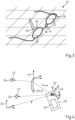
- the Fig. 1 shows as a scene 10 a table 12 with a tablecloth 14, on which a pair of glasses 16 with a frame 18 and with a left and right lens 20, 22 accommodated in it, along with other objects 24 in the form of a knife, a bottle, a cup and a book as well as a cigar.
- the scene 10 shown is time-invariant and contains as structure points 26 characteristic points of a pattern of the tablecloth 14 and the objects 24, which define a coordinate system 25 of the scene 10, as well as characteristic points of the spectacle frame 18 of the spectacles 16.
- the scene 10 is recorded using the camera 28 in an image capture device 30 designed as a smartphone in a variety of different recording positions 32, 34, 36, ... by a user holding the smartphone switched to video mode with one hand and moving it along a trajectory 38.
- the user thus records the scene 10 using the camera 28 of the image capture device 30 from different perspectives.
- the image capture device 30 contains a computer unit 40 for processing the recordings of the scene 10 recorded using the camera 28.
- the Fig. 2 is a section 42 of a first image of the scene 10 captured by the image capture device 30 from a first recording position 32 with images 26' of structural points 26.
- a further section 42 of a first image of the scene 10 with images 26' of structural points 26 captured by means of the image capture device 30 from a further recording position 36 different from the first recording position 32 is shown.
- a plurality of structural points 26 are each captured with an imaging beam path that passes through or does not pass through the first and/or the second spectacle lens 20, 22 in the spectacle frame 18 of the spectacles 16.
- images of the scene 10 which contain a section of the spectacle frame 18 defining a coordinate system 44 of the spectacle frame 18.
- the Fig. 4 shows the coordinate system 25 of the scene 10 and a coordinate system 46 of the image capture device 30 with a spectacle lens 20, 22. From the many captured images of the scene 10, the computer unit 40 in the image capture device 30 calculates the coordinates of the structure points 26 of a pattern 27 in the scene using a SLAM algorithm by means of a ray model in a coordinate system 46 referenced to the image capture device 30, which in turn is referenced to the coordinate system 25 of the scene 10 and the coordinate system 44 of the spectacle frame 18 of the spectacles 16.
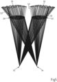
- the Fig. 5 shows a ray model of the glasses 16 with imaging beam paths guided into the camera 28 of the image capture device 30 with main rays 53, 53' for structure points 26 when the scene 10 is captured from two different recording positions 32, 34.
- a ray model not only requires knowledge of the positions of the image capture device 30 but also requires a three-dimensional model for the scene 10 as well as knowledge of the position of the Fig. 1 shown glasses 16 in the scene 10 and, in addition, also the information as to which structural points 26 in the scene 10 the image capture device 30 captures through the left lens 20 or the right lens 22 of the glasses 16.
- the position of each of these structural points 26 in the scene 10 in the coordinate system 46 of the image capture device 30 can be deduced from the intrinsic parameters of the image capture device as well as the location and position of an image capture device at the time of capturing an image.
- a main ray 53, 53' which passes through a lens 20, 22 of the glasses 16, is then calculated according to the position of the image capture device 30. From this and from the 3D coordinate of the point, a ray model is then obtained which reflects various viewing conditions of the same glasses 16 in the same scene 10 and which describes imaging rays which are deflected and which correspond to the various positions of an image capture device.
- An inverse approach is a reversal of the so-called forward calculation, in which the course of light rays through an optical system consisting of known optical interfaces and known refractive indices between the interfaces is calculated in an optical ray calculation, which is also known as ray tracing. Provided that the interfaces, their normals and the refractive indices are known, it is possible to calculate each light ray through the system unambiguously.
- an optical interface or refractive index is sought that matches a given number of light rays.
- the forward calculation is carried out using the area determined using the inverse approach and a comparison is then made of ray points in front of and/or behind the respective interface.
- the error size is then specifically minimized using an optimization process.
- pure optimization methods which can determine the minimum of an error function through parameter variations
- light path triangulation methods which can also be used in combination with an optimization method.
- the dioptric power of the lenses can be calculated, if their shape and refractive index are known, in particular by forward calculation of beams of rays.
- the vertex power of a lens can be determined, for example, by propagating a parallel beam of rays, the diameter of which is about 5 mm and thus corresponds to the size of the eye's pupil, through the lens in such a way that its main ray, ie its optical axis, leaves the lens perpendicularly on the eye side.
- the value of the vertex power is then the reciprocal of the distance from the surface of the lens from which the main ray emerges to the point of the smallest beam waist or extension of the beam of rays.
- the direction-dependent expansion of the beam of rays has two minima.
- the distance between these two minima and the surface of the lens describes the effect of the two main sections.
- the difference between these two main sections describes the cylindrical effect of the lens.
- the entire deflection of the main ray by the lens is to be regarded as the prismatic effect of the lens at the respective point.
- the so-called intrinsic camera calibration operator is used to convert pixel coordinates C of the camera 28 in the image capture device 30 to the beam vector of an imaging beam path. K .
- the camera calibration operator K can be determined, for example, from a recording of a special calibration pattern, e.g. a checkerboard pattern or a dot pattern, using the image capture device.
- a special calibration pattern e.g. a checkerboard pattern or a dot pattern
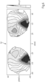
- Fig. 6 is a graph 52 to a based on the in the Fig. 5
- the distribution of the refractive power k(x,y) for the left and right lenses 20, 22 calculated from the ray model of the spectacles 16 shown can be seen.
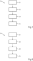
- the Fig. 7 is a flow chart 54 of the method described above for measuring a left and/or right spectacle lens 20, 22 in a pair of spectacles 16.
- a first step S1 at least a first image of a scene 10 with a plurality of structure points 26 and with a left and/or a right spectacle lens 20, 22 in a pair of spectacles 16 and with a section of the The spectacle frame 18 of the spectacles 16 is captured by means of an image capture device 30 with an imaging beam path for structural points 26 which passes through the first and/or the second spectacle lens 20, 22 of the spectacles 16.
- step S2 following step S1, at least two further images of the scene 10 without the first and/or the second spectacle lens 20, 22 of the spectacles 16 with the structural points 26 depicted in the first image are then captured by means of the image capture device 30.
- a step S3 the coordinates of the stationary, time-invariant structure points 26 in the coordinate system 25 of the scene 10 referenced to the coordinate system 46 of the image capture device 30 in the different recording positions are then calculated from the at least two further images of the scene 10 by means of image evaluation.
- step S4 the refractive power distribution k(x, y) is then determined for at least one section of the left spectacle lens 20 in the coordinate system 44 of the spectacle frame 18 referenced to the coordinate system 25 of the scene 10 and/or the refractive power distribution k(x, y) is determined for at least one section of the right spectacle lens 22 in a coordinate system 25 of the scene 10 referenced to the coordinate system 44 of the spectacle frame 18 from the coordinates of the stationary, time-invariant structural points 26 and the image of the structural points 26 in the at least one first image of the scene 10.
- the Fig. 8 shows a flow chart 54 for an alternative method to the method described above for measuring a left and/or right spectacle lens 20, 22 in a pair of spectacles 16, which is described below with reference to the Fig. 9 to Fig. 12 described.
- a first step S1 as in the Fig. 9 to be seen, by means of an image capture device 30 a sequence of first images of a time-invariant scene 10 with a plurality of structure points 26 and with a left and/or a right spectacle lens 20, 22 in a pair of spectacles 16 is captured together with a portion of the spectacle frame 18 which has a Fig. 4 shown coordinate system 44 of the spectacle frame 18 is defined.
- the capture of images of the scene 10 is carried out with imaging beam paths for structure points 26, which at least partially penetrate the first and/or the second spectacle lens 20, 22 of the spectacles 16 and are at least partially guided past the first and/or the second spectacle lens 20, 22 of the spectacles 16.
- step S2 following step S1, as in the Fig. 10
- a sequence of further images of the scene 10 with stationary, time-invariant structure points 26, but without the glasses 16, is captured. It should be noted that step S2 can also occur before step S1 or at the same time.
- a step S3 the coordinate system 25 of the scene 10 is referenced to the coordinate system 44 of the spectacle frame 18 and the coordinates of the structure points 26 in the coordinate system 25 of the scene 10 referenced to the coordinate system 46 of the image capture device 30 in the different recording positions are then calculated from the at least one further image of the scene 10 by means of image analysis.
- the refractive power distribution k(x,y) is determined for at least one section of the left spectacle lens 20 in the coordinate system 44 of the spectacle frame 18 referenced to the coordinate system 25 of the scene 10 and/or the refractive power distribution k(x,y) is determined for at least one section of the right spectacle lens 22 in the coordinate system 44 of the spectacle frame 18 from the coordinates of the structure points 26 and the image the structure points 26 in the at least one first image of the scene 10.
- the measurement of a left and/or right spectacle lens 20, 22 in a spectacle frame 18 is also possible by capturing images of a scene 10 in which a spectacle wearer is present with and without spectacles.
- a sequence of first images of a time-invariant scene 10 with a plurality of structure points 26 and with a left and/or a right spectacle lens 20, 22 in a spectacle frame 18 is captured together with a section of the spectacle frame 18 which defines a coordinate system 44 of the spectacle frame 18.
- the capture of images of the scene 10 takes place with imaging beam paths for structure points 26 which at least partially penetrate the first and/or the second spectacle lens 20, 22 of the spectacles 16 and which are at least partially guided past the first and/or the second spectacle lens 20, 22 of the spectacles 16.
- a sequence of further images of the scene 10 with structure points 26, but without the glasses 16, is recorded.
- the coordinates of the structure points 26 are then calculated in a coordinate system 25 of the scene 10 referenced to the coordinate system 46 of the image capture device 30 at different recording positions from the at least one further image of the scene 10 by means of image analysis and the coordinate system 25 of the scene 10 is referenced to the coordinate system 44 of the glasses frame 18.
- the refractive power distribution k(x,y) is then determined for at least one section of the left glasses lens 20 in the coordinate system 44 of the glasses frame 18 and/or the refractive power distribution k(x,y) is determined for at least one section of the right glasses lens 22 in the coordinate system 44 of the glasses frame 18 from the coordinates of the structure points 26 and the image of the Structural points 26 in the at least one first image of the scene 10 are determined.
- the computer unit of the image capture device 30 contains a program routine by means of which the position of the structure points 26 is calculated by evaluating neighborhood relationships, in particular distances between the structure points 26 in the scene 10, in a coordinate system 25 of the scene 10 referenced to the coordinate system 44 of the spectacle frame 18.
- the invention relates to a method for measuring the local refractive power or the refractive power distribution of a left and/or a right spectacle lens 20, 22 in a spectacle frame 18.
- at least a first image of a scene 10 with at least one structural point 26 and with a left and/or a right spectacle lens 20, 22 in a spectacle frame 18 is captured by means of an image capture device 30 from at least a first recording position 32 with at least one imaging beam path for structural points 26, which passes through the first and/or the second spectacle lens 20, 22 in the spectacle frame 18.
- At least two further images of the scene 10 are captured without the first and/or the second spectacle lens 20, 22 of the spectacle frame 18 or without the spectacle frame containing the left and/or the right spectacle lens with the structural points 26 depicted in the first image are captured by means of the image capture device 30 from at least two different recording positions 32, 34, 36, one of which can be identical to the first recording position, and the coordinates of the structural points 26 are calculated in a coordinate system 25 from the at least two further images of the scene 10 by means of image analysis, or at least two further images of the scene 10 with the left and/or the right spectacle lens 20, 22 are captured by means of an image capture device 30 from at least two further recording positions different from the first recording position with at least one imaging beam path for the structural points 26 depicted in the first image, which does not pass through the first and/or the second spectacle lens 20, 22 of the spectacle frame 18, in order to then calculate a refractive power distribution k(x,y) for at least a portion of the left spectacle lens 20 in a coordinate system 25 of the scene 10 referenced
Landscapes
- Physics & Mathematics (AREA)
- General Physics & Mathematics (AREA)
- Engineering & Computer Science (AREA)
- Ophthalmology & Optometry (AREA)
- Health & Medical Sciences (AREA)
- Optics & Photonics (AREA)
- Chemical & Material Sciences (AREA)
- Analytical Chemistry (AREA)
- Computer Vision & Pattern Recognition (AREA)
- Theoretical Computer Science (AREA)
- Geometry (AREA)
- General Health & Medical Sciences (AREA)
- Eyeglasses (AREA)
- Testing Of Optical Devices Or Fibers (AREA)
- Eye Examination Apparatus (AREA)
- Investigating Or Analysing Materials By Optical Means (AREA)
Description
Die Erfindung betrifft ein Verfahren zum Vermessen der lokalen Brechkraft und/oder der Brechkraftverteilung eines linken und/oder eines rechten Brillenglases, vorzugsweise in einer Brillenfassung. Darüber hinaus betrifft die Erfindung ein Computerprogrammprodukt mit einem Computerprogramm mit Programmcode sowie eine Vorrichtung zur Durchführung des Verfahrens.The invention relates to a method for measuring the local refractive power and/or the refractive power distribution of a left and/or right spectacle lens, preferably in a spectacle frame. In addition, the invention relates to a computer program product with a computer program with program code and a device for carrying out the method.
Um einem Brillenträger das scharfe Sehen zu ermöglichen, müssen die Brillengläser in der Brillenfassung zu den Augen des Brillenträgers korrekt positioniert und ausgerichtet werden. Das korrekte Ausrichten und Positionieren ist grundsätzlich bei allen Brillengläsern erforderlich. Besondere Bedeutung hat das korrekte Ausrichten und Positionieren der Brillengläser insbesondere bei individualisierten optischen Brillenglasdesigns, bei torischen Brillenglasdesigns, bei Brillengläsern mit hoher dioptrischer Wirkung und bei Gleitsicht-Brillengläsern. Gleitsicht-Brillengläser ermöglichen Brillenträgern das scharfe Sehen in unterschiedlichen Gebrauchssituationen, z. B. in unterschiedlichen Entfernungen, nur durch Verändern der Blickrichtung, ohne dass es dabei eines größeren Akkommodationserfolges der Augen bedarf. Gleitsicht-Brillengläser sind gemäß DIN EN ISO 13666:2013-10, Absatz 8.3.5 Brillengläser mit mindestens einer Gleitsichtfläche und einer zunehmenden (positiven) dioptrischen Wirkung, wenn der Brillenträger nach unten blickt. Individualisierte Brillengläser und/oder Gleitsicht-Brillengläser haben einen oder mehrere Bezugspunkte, z. B. einen Fern-Durchblickpunkt und/oder einen Nah-Durchblickpunkt, deren Lage je nach Gebrauchssituation an den Ort der Pupillen der Augen eines Brillenträgers angepasst werden muss. Der Fern-Durchblickpunkt ist gemäß DIN EN ISO 13666:2013-10, Absatz 5.16, die angenommene Lage des Durchblickpunkts auf einem Brillenglas für das Sehen in die Ferne unter bestimmten Bedingungen. Der Nah-Durchblickpunkt ist gemäß DIN EN ISO 13666:2013-10, Absatz 5.17, die angenommene Lage des Durchblickpunkts auf einem Brillenglas für das Sehen in die Nähe unter bestimmten Bedingungen. Bei torischen Brillenglasdesigns besteht außerdem die Notwendigkeit der für einen Brillenträger richtigen Orientierung ihrer zylindrischen Wirkung.In order to enable a spectacle wearer to see clearly, the lenses in the frame must be correctly positioned and aligned with the wearer's eyes. Correct alignment and positioning is fundamentally required for all spectacle lenses. Correct alignment and positioning of the lenses is particularly important for customized optical lens designs, toric lens designs, lenses with a high dioptric effect and progressive lenses. Progressive lenses enable spectacle wearers to see clearly in different usage situations, e.g. at different distances, just by changing the direction of gaze, without the eyes requiring greater accommodation. According to DIN EN ISO 13666:2013-10, paragraph 8.3.5, progressive lenses are lenses with at least one progressive surface and an increasing (positive) dioptric effect when the wearer looks downwards. Individualised lenses and/or progressive lenses have one or more reference points, e.g. a distance visual point and/or a near visual point, the position of which must be adapted to the location of the pupils of the wearer's eyes depending on the situation in which they are being used. The distance visual point is, according to DIN EN ISO 13666:2013-10, paragraph 5.16, the assumed position of the visual point on a lens for seeing into the distance under certain conditions. The near visual point is, according to DIN EN ISO 13666:2013-10, paragraph 5.17, the assumed position of the visual point on a spectacle lens for near vision under certain conditions. In toric lens designs, there is also the need for the correct orientation of their cylindrical power for a spectacle wearer.
Aus der
Die
Die
Aus der
Die
Die
Aufgabe der Erfindung ist es, auf einfache Weise und ohne großen apparativen Aufwand die fokussierende oder die dioptrische Wirkung eines linken und/oder eines rechten Brillenglases jeweils für die Ferne und/oder für die Nähe zu bestimmen. Insbesondere ist es eine Aufgabe der Erfindung, eine lokale Brechkraft an unterschiedlichen Stellen auf einem Brillenglas, d. h. eine Brechkraftverteilung, mit einer hohen Genauigkeit zu ermitteln.The object of the invention is to determine the focusing or dioptric effect of a left and/or right spectacle lens for distance and/or near vision in a simple manner and without great expenditure on equipment. In particular, it is an object of the invention to determine a local refractive power at different points on a spectacle lens, i.e. a refractive power distribution, with a high degree of accuracy.
Diese Aufgabe wird durch das in Anspruch 1 und Anspruch 2 angegebene Verfahren gelöst. Vorteilhafte Weiterbildungen der Erfindung sind in den abhängigen Ansprüchen angegeben.This object is achieved by the method specified in
Bei dem in Anspruch 1 angegebenen Verfahren zum Vermessen der lokalen Brechkraft eines linken und/oder eines rechten Brillenglases in einer Brillenfassung wird in einem ersten Schritt mittels wenigstens einer Bilderfassungseinrichtung wenigstens eine erste Abbildung einer Szene aus wenigstens einer ersten Aufnahmeposition erfasst, wobei diese wenigstens eine erste Abbildung viele Strukturpunkte aufweist und ein linkes und/oder ein rechtes Brillenglas in einer Brillenfassung enthält, wobei der wenigstens eine Abbildungsstrahlengang für jeden dieser Strukturpunkte das erste oder das zweite Brillenglas der Brillenfassung durchsetzt.In the method specified in
Unter Brechkraft versteht diese Erfindung die fokussierende Wirkung oder die dioptrische Wirkung eines Brillenglases. Unter der fokussierenden Wirkung versteht diese Erfindung entsprechend der in DIN EN ISO 13666:2013-10, Absatz 9.2, angegebenen Definition den Sammelbegriff für die sphärische und astigmatische Wirkung eines Brillenglases. Unter der dioptrischen Wirkung eines Brillenglases versteht diese Erfindung entsprechend der in DIN EN ISO 13666:2013-10, Absatz 9.3, angegebenen Definition den Sammelbegriff für die fokussierende und die prismatische Wirkung des Brillenglases. Unter der prismatischen Wirkung eines Brillenglases versteht diese Erfindung entsprechend der in DIN EN ISO 13666:2013-10, Absatz 10.9, angegebenen Definition den Sammelbegriff für prismatische Ablenkung und Basislage.This invention understands the refractive power to be the focusing effect or the dioptric effect of a spectacle lens. This invention understands the focusing effect to be the collective term for the spherical and astigmatic effect of a spectacle lens in accordance with the definition given in DIN EN ISO 13666:2013-10, paragraph 9.2. This invention understands the dioptric effect of a spectacle lens in accordance with the definition given in DIN EN ISO 13666:2013-10, paragraph 9.3. This invention understands the dioptric effect of a spectacle lens to be the collective term for the focusing and prismatic effect of the spectacle lens in accordance with the definition given in DIN EN ISO 13666:2013-10, paragraph 9.3. This invention understands the prismatic effect of a spectacle lens as the collective term for prismatic deflection and base position according to the definition given in DIN EN ISO 13666:2013-10, paragraph 10.9.
Unter lokaler Brechkraft versteht diese Erfindung die lokale fokussierende Wirkung oder die lokale dioptrische Wirkung eines Brillenglases.For the purposes of this invention, local refractive power means the local focusing effect or the local dioptric effect of a spectacle lens.
Unter Brechkraftverteilung versteht diese Erfindung die ortsaufgelöste fokussierende Wirkung oder die ortsaufgelöste dioptrische Wirkung eines Brillenglases.For this invention, refractive power distribution means the spatially resolved focusing effect or the spatially resolved dioptric effect of a spectacle lens.
Unter einer Szene versteht die Erfindung einen Abschnitt einer Umgebung, der mit wenigstens einer Bilderfassungseinrichtung, z. B. mit wenigstens einer digitalen Kamera erfasst werden kann, die beispielsweise in ein Smartphone oder in einen Tablet-Computer integriert ist. Eine Szene kann z. B. ein Abschnitt eines Zimmers in einer Wohnung oder ein Abschnitt eines Ladenlokals oder ein Teil einer Landschaft sein. Eine Szene kann allerdings auch ein Gesicht oder nur ein linkes Auge und/oder ein rechtes Auge eines Brillenträgers der Brille enthalten.The invention understands a scene to be a section of an environment that can be captured with at least one image capture device, e.g. with at least one digital camera that is integrated, for example, in a smartphone or a tablet computer. A scene can be, for example, a section of a room in an apartment or a section of a shop or a part of a landscape. However, a scene can also contain a face or just a left eye and/or a right eye of a person wearing the glasses.
Unter wenigstens einem Strukturpunkt einer Szene wird vorliegend ein geometrischer Punkt verstanden, dessen Bild in wenigstens einer Abbildung oder Aufnahme der Szene durch Erfassen der Szene mit wenigstens einer Bilderfassungseinrichtung aufgrund einer zu dem Bild dieses Punkts unterschiedlichen Helligkeit und/oder Farbe eines Bilds von zu diesem Punkt benachbarten Punkten eindeutig zu erkennen ist. Ein Strukturpunkt kann z. B. an einer Ecke oder Kante einer Struktur in der Szene liegen.In the present case, at least one structural point of a scene is understood to mean a geometric point whose image can be clearly recognized in at least one image or recording of the scene by capturing the scene with at least one image capture device due to a brightness and/or color of an image of points adjacent to this point that is different from the image of this point. A structural point can, for example, be located at a corner or edge of a structure in the scene.
Von dem Begriff Strukturpunkt einer Szene ist vorliegend allerdings auch ein Punkt in einem ortsfesten, zeitinvarianten Muster erfasst, z. B. wenigstens ein Punkt in einem regelmäßigen oder unregelmäßigen Punktemuster, wenigstens ein Punkt in einem regelmäßigen oder unregelmäßigen Streifenmuster, wenigstens ein Punkt in einem regelmäßigen oder unregelmäßigen Karomuster, wenigstens ein Punkt in einem Barcode, wenigstens ein Punkt in einem 2D-Code und/oder wenigstens ein Punkt innerhalb eines geschriebenen Textes, beispielsweise einer Zeitung oder eines Buches oder eines elektronischen Anzeigegerätes, z.B. eines Bildschirms, sein. Insbesondere kann wenigstens ein ortsfester, zeitinvarianter Strukturpunkt in einer Szene wenigstens ein Punkt auf einer strukturierten Oberfläche, beispielsweise einer strukturierten Tischdecke oder auf einer strukturierten Tapete sein.However, the term structural point of a scene also includes a point in a stationary, time-invariant pattern, e.g. at least one point in a regular or irregular point pattern, at least one point in a regular or irregular stripe pattern, at least one point in a regular or irregular checkered pattern, at least one point in a barcode, at least one point in a 2D code and/or at least one point within a written text, for example a newspaper or a book or an electronic display device, eg a screen. In particular, at least one stationary, time-invariant structural point in a scene can be at least one point on a structured surface, for example a structured tablecloth or on a structured wallpaper.
Unter dem Begriff Strukturpunkt einer Szene wird vorliegend allerdings auch wenigstens ein Punkt in einer Szene verstanden, dessen Lage sich zeitlich verändern kann, wie z. B. wenigstens ein Punkt in dem Gesicht eines Brillenträgers, das sich bewegt, etwa ein Punkt auf Augenbrauen, auf Lippen oder ein auf der Iris liegender Punkt. Wenn sich die Lage des wenigstens einen Strukturpunktes in einer Szene zeitlich verändert, wird bevorzugt, soweit möglich, dessen Verschiebung rekonstruiert und dann bei der Bestimmung der lokalen Brechkraft eines linken und/oder rechten Brillenglases berücksichtigt. Für den Fall, dass die Verschiebung eines solchen Strukturpunkts nicht rekonstruierbar ist, ist es von Vorteil, wenn dieser Strukturpunkt bei einer Bestimmung der lokalen Brechkraft und/oder der Brechkraftverteilung eines linken und/oder rechten Brillenglases nicht berücksichtigt wird.However, the term structural point of a scene is also understood here to mean at least one point in a scene whose position can change over time, such as at least one point in the face of a glasses wearer that is moving, such as a point on the eyebrows, on the lips or a point on the iris. If the position of the at least one structural point in a scene changes over time, its displacement is preferably reconstructed as far as possible and then taken into account when determining the local refractive power of a left and/or right spectacle lens. In the event that the displacement of such a structural point cannot be reconstructed, it is advantageous if this structural point is not taken into account when determining the local refractive power and/or the refractive power distribution of a left and/or right spectacle lens.
Unter wenigstens einer Bilderfassungseinrichtung versteht die Erfindung bevorzugt eine digitale Kamera, welche z. B. in einem mobilen Endgerät, wie einem Mobiltelefon, einem Smartphone oder einem Tablet-Computer integriert ist. Die digitale Kamera kann als eine Stereokamera, als eine Multikamera, als ein Bildsensor mit einem Objektiv oder als ein Bildsensor mit wenigstens zwei Objektiven und/oder als eine sogenannte plenoptische Kamera ausgebildet sein. Zu bemerken ist, dass ein stehend angegebenes mobiles Endgerät auch mehrere Bilderfassungseinrichtungen in Form einer digitalen Kamera aufweisen kann.The invention preferably understands at least one image capture device to be a digital camera, which is integrated, for example, in a mobile terminal such as a mobile phone, a smartphone or a tablet computer. The digital camera can be designed as a stereo camera, as a multi-camera, as an image sensor with one lens or as an image sensor with at least two lenses and/or as a so-called plenoptic camera. It should be noted that a mobile terminal specified as standing can also have several image capture devices in the form of a digital camera.
Unter einem mobilen Endgerät ist insbesondere eine Vorrichtung zu verstehen, welche zumindest einen programmierbaren Prozessor sowie wenigstens eine Bilderfassungseinrichtung, z.B. wenigstens eine Kamera, und wenigstens einen Beschleunigungssensor umfasst, und welche bevorzugt dazu ausgelegt ist, getragen zu werden, d.h. hinsichtlich Dimensionen und Gewicht derart ausgestaltet ist, dass sie von einer Person mitführbar ist. In dem mobilen Endgerät können weitere Komponenten vorhanden sein, wie zum Beispiel wenigstens ein Bildschirm, wenigstens eine Lichtquelle für beispielsweise sichtbares Licht aus einem Wellenlängenbereich von 380 nm bis 780 nm und/oder infrarotes Licht aus einem Wellenlängenbereich von 780 nm bis 1 mm und/oder wenigstens ein Lichtempfänger mit einer Sensibilität für beispielsweise sichtbares Licht aus einem Wellenlängenbereich von 380 nm bis 780 nm und/oder infrarotes Licht aus einem Wellenlängenbereich von >780 nm bis 1 mm. Typische Beispiele für derartige mobile Endgeräte sind Smartphones oder Tablet-PCs, die wenigstens einen Bildschirm, beispielsweise einen Sensorbildschirm (Touchscreen), wenigstens eine Bilderfassungseinrichtung, z.B. wenigstens eine Kamera, wenigstens einen Beschleunigungssensor, wenigstens eine Lichtquelle, wenigstens einen Lichtempfänger und weitere Komponenten, wie drahtlosen Schnittstellen für Mobilfunk oder WLAN (Wireless LAN) aufweisen können.A mobile terminal is understood to mean in particular a device which comprises at least one programmable processor and at least one image capture device, e.g. at least one camera, and at least one acceleration sensor, and which is preferably designed to be carried, i.e. is designed in such a way in terms of dimensions and weight that it can be carried by a person. The mobile terminal can contain further components, such as at least one screen, at least one light source for, for example, visible light from a wavelength range of 380 nm to 780 nm and/or infrared light from a wavelength range of 780 nm to 1 mm and/or at least one light receiver with a sensitivity for, for example, visible light from a wavelength range of 380 nm to 780 nm and/or infrared light from a wavelength range of >780 nm to 1 mm. Typical examples of such mobile devices are smartphones or tablet PCs, which can have at least one screen, for example a sensor screen (touchscreen), at least one image capture device, e.g. at least one camera, at least one acceleration sensor, at least one light source, at least one light receiver and other components, such as wireless interfaces for mobile communications or WLAN (wireless LAN).
Unter einem Abbildungsstrahlengang für einen Strukturpunkt wird vorliegend der Verlauf der Lichtstrahlen verstanden, die eine optische Abbildung des Strukturpunkts aus der Szene als ein Strukturpunktbild in die Abbildung der Szene in wenigstens einer Bilderfassungseinrichtung bewirken. Als der Hauptstrahl des Abbildungsstrahlengangs für einen Strukturpunkt wird im Folgenden dessen eine Symmetrieachse bildende optische Achse bezeichnet.In the present case, an imaging beam path for a structural point is understood to mean the course of the light rays that cause an optical imaging of the structural point from the scene as a structural point image into the image of the scene in at least one image capture device. The main ray of the imaging beam path for a structural point is referred to below as the optical axis that forms an axis of symmetry.
Bei dem in Anspruch 1 angegebenen Verfahren werden in einem weiteren Schritt, der zeitlich vor oder nach dem ersten Schritt liegen oder gleichzeitig mit dem ersten erfolgen kann, wenigstens zwei weitere Abbildungen der Szene ohne das erste und/oder das zweite Brillenglas der Brillenfassung oder ohne die Brillenfassung enthaltend das erste und/oder das zweite Brillenglas mit den in der ersten Abbildung abgebildeten Strukturpunkten mittels wenigstens einer Bilderfassungseinrichtung aus wenigstens zwei verschiedenen Aufnahmepositionen erfasst, wobei wenigstens eine der Aufnahmepositionen identisch zu der wenigstens einen ersten Aufnahmeposition sein kann. Die wenigstens eine Bilderfassungseinrichtung kann in dem weiteren Schritt identisch oder verschieden zu der wenigstens einen Bilderfassungseinrichtung aus dem ersten Schritt sein. Bevorzugt ist die wenigstens eine Bilderfassungseinrichtung in dem weiteren Schritt identisch zu der wenigstens einen Bilderfassungseinrichtung aus dem ersten Schritt. Darauf werden in einem Schritt des Berechnens die Koordinaten der Strukturpunkte in einem Koordinatensystem aus den wenigstens zwei weiteren Abbildungen der Szene mittels Bildauswertung mittels Triangulation bestimmt. Im Anschluss daran wird die lokale Brechkraft in einem Schritt des Bestimmens einer lokalen Brechkraft für wenigstens einen Abschnitt des linken Brillenglases und/oder einen Abschnitt des rechten Brillenglases aus den Koordinaten der Strukturpunkte und dem Bild der Strukturpunkte in der wenigstens einen ersten Abbildung der Szenemittels eines inversen Ansatzes bestimmt, bei dem aus den Abbildungsstrahlengängen für die Strukturpunkte die optischen Grenzflächen des linken und/oder rechten Brillenglases berechnet werden, indem durch Variation der jeweils zu bestimmenden Grenzfläche eine Fehlergröße minimiert wird, wobei die Fehlergröße zu der Grenzfläche bestimmt wird, indem mittels Ray-Tracing ein Vergleich von Strahlpunkten vor und hinter der Grenzfläche erstellt wird.In the method specified in
Das in Anspruch 2 angegebene Verfahren zum Vermessen der lokalen Brechkraft eines linken und/oder eines rechten Brillenglases in einer Brillenfassung sieht vor, in einem ersten Schritt mittels wenigstens einer Bilderfassungseinrichtung wenigstens eine erste Abbildung einer Szene aus wenigstens einer ersten Aufnahmeposition zu erfassen, wobei diese wenigstens eine erste Abbildung viele Strukturpunkte aufweist und ein linkes und/oder ein rechtes Brillenglas in einer Brillenfassung enthält, wobei der wenigstens eine Abbildungsstrahlengang für jeden dieser Strukturpunkte das erste oder das zweite Brillenglas der Brillenfassung durchsetzt.The method specified in claim 2 for measuring the local refractive power of a left and/or a right spectacle lens in a spectacle frame provides, in a first step, for capturing at least one first image of a scene from at least one first recording position by means of at least one image capturing device, wherein this at least one first image has many structure points and a left and/or a right spectacle lens in a spectacle frame, wherein the at least one imaging beam path for each of these structural points passes through the first or the second spectacle lens of the spectacle frame.
Wie oben angegeben wird vorliegend unter dem Abbildungsstrahlengang für einen Strukturpunkt der Verlauf der Lichtstrahlen verstanden, die eine optische Abbildung des Strukturpunkts aus der Szene als ein Strukturpunktbild in die mittels wenigstens einer Bilderfassungseinrichtung erfasste Abbildung der Szene bewirken. Als der Hauptstrahl des Abbildungsstrahlengangs für einen Strukturpunkt wird im Folgenden dessen eine Symmetrieachse bildende optische Achse bezeichnet.As stated above, the imaging beam path for a structural point is understood here to mean the course of the light rays that cause an optical imaging of the structural point from the scene as a structural point image in the image of the scene captured by at least one image capture device. The optical axis forming an axis of symmetry is referred to below as the main ray of the imaging beam path for a structural point.
In einem weiteren Schritt, der zeitlich vor oder nach dem ersten Schritt liegen kann oder der gleichzeitig mit dem ersten Schritt erfolgen kann, werden wenigstens zwei weitere Abbildungen der Szene mit dem linken und/oder dem rechten Brillenglas in einer Brillenfassung mittels wenigstens einer Bilderfassungseinrichtung aus wenigstens zwei unterschiedlichen von der ersten Aufnahmeposition verschiedenen weiteren Aufnahmepositionen mit jeweils wenigstens einem Abbildungsstrahlengang für die in der ersten Abbildung abgebildeten Strukturpunkte erfasst, wobei dieser wenigstens eine Abbildungsstrahlengang das erste und das zweite Brillenglas der Brillenfassung nicht durchsetzt. Darauf werden in einem weiteren Schritt die Koordinaten der Strukturpunkte in einem Koordinatensystem aus dem jeweiligen wenigstens einen Strahlengang der Strukturpunkte, welche das linke und rechte Brillenglas nicht durchsetzt haben, mittels Bildauswertung mittels Triangulation berechnet. Anschließend wird die lokale Brechkraft für wenigstens einen Abschnitt des linken Brillenglases und/oder für wenigstens einen Abschnitt des rechten Brillenglases jeweils aus den Koordinaten der Strukturpunkte und dem Bild der Strukturpunkte in der wenigstens einen ersten Abbildung der Szene mittels eines inversen Ansatzes bestimmt, bei dem aus den Abbildungsstrahlengängen für die Strukturpunkte die optischen Grenzflächen des linken und/oder rechten Brillenglases berechnet werden, indem durch Variation der jeweils zu bestimmenden Grenzfläche eine Fehlergröße minimiert wird, wobei die Fehlergröße zu der Grenzfläche bestimmt wird, indem mittels Ray-Tracing ein Vergleich von Strahlpunkten vor und hinter der Grenzfläche erstellt wird..In a further step, which can be before or after the first step or can take place at the same time as the first step, at least two further images of the scene with the left and/or right spectacle lens in a spectacle frame are captured by means of at least one image capture device from at least two different further recording positions different from the first recording position, each with at least one imaging beam path for the structural points depicted in the first image, wherein this at least one imaging beam path does not pass through the first and second spectacle lenses of the spectacle frame. Then, in a further step, the coordinates of the structural points in a coordinate system are calculated from the respective at least one beam path of the structural points that did not pass through the left and right spectacle lenses by means of image analysis using triangulation. Subsequently, the local refractive power for at least one section of the left spectacle lens and/or for at least one section of the right spectacle lens is determined from the coordinates of the structure points and the image of the structure points in the at least one first image of the scene by means of an inverse approach in which the optical interfaces of the left and/or right The optical properties of a spectacle lens can be calculated by minimizing an error size by varying the interface to be determined in each case, whereby the error size at the interface is determined by using ray tracing to create a comparison of ray points in front of and behind the interface.
In einer vorteilhaften Weiterbildung eines vorstehend angegebenen Verfahrens zum Vermessen der lokalen Brechkraft eines linken und/oder eines rechten Brillenglases, vorzugsweise in einer Brillenfassung, werden eine Vielzahl von Strukturpunkten in einer Szene aus jeweils wenigstens einer ersten Aufnahmeposition in jeweils einer ersten Abbildung der Szene erfasst und es werden die auf das Erfassen folgenden Schritte anhand dieser jeweiligen Vielzahl von Strukturpunkten vorgenommen.In an advantageous development of a method specified above for measuring the local refractive power of a left and/or a right spectacle lens, preferably in a spectacle frame, a plurality of structural points in a scene are recorded from at least one first recording position in a first image of the scene, and the steps following the recording are carried out on the basis of this respective plurality of structural points.
Unter einer Vielzahl von Strukturpunkten wird vorliegend eine aus mindestens drei Strukturpunkten bestehende Punktemenge verstanden. Von Vorteil ist es, wenn das Vermessen der lokalen Brechkraft eines linken und/oder eines rechten Brillenglases anhand von wenigstens 10, bevorzugt wenigstens 100, besonders bevorzugt wenigstens 1000 und ganz besonders bevorzugt wenigstens 10000 Strukturpunkten erfolgt. Günstig ist, wenn das Vermessen der lokalen Brechkraft eines linken und/oder rechten Brillenglases anhand einer Anzahl Z von Strukturpunkten erfolgt, für die gilt: 100 ≤ Z ≤ 1000.In the present case, a plurality of structural points is understood to mean a set of points consisting of at least three structural points. It is advantageous if the local refractive power of a left and/or right spectacle lens is measured using at least 10, preferably at least 100, particularly preferably at least 1000 and very particularly preferably at least 10,000 structural points. It is advantageous if the local refractive power of a left and/or right spectacle lens is measured using a number Z of structural points for which the following applies: 100 ≤ Z ≤ 1000.
Indem die lokale Brechkraft an einer Vielzahl von unterschiedlichen Stellen des linken und/oder rechten Brillenglases vermessen wird, ist es möglich, für das linke und/oder rechte Brillenglas eine Brechkraftverteilung zu bestimmen.By measuring the local refractive power at a variety of different locations on the left and/or right lens, it is possible to determine a refractive power distribution for the left and/or right lens.
Die Bildauswertung jeder Abbildung umfasst bevorzugt bildverarbeitende Technologien, wie beispielsweise Klassifizierung, Segmentierung und Triangulation. Mit Hilfe von Verfahren zur Objekterkennung, wie Segmentierung und Klassifizierung, wird jede Abbildung bevorzugt nach Objekten der Klassen Szene und/oder Brillenfassung untersucht. Die Verfahren zur Objekterkennung können sowohl klassischer Natur, wie z.B. Thresholding, kanten- oder regionsbasierte Segmentierung, optischer Fluss als auch lernender Natur sein. Sind die Verfahren zur Objekterkennung lernender Natur, wie bei der Anwendung von lernenden Algorithmen, ist es notwendig, im Vorfeld ein neuronales Netzwerk mit augmentierten Trainingsdaten zu trainieren. Das Ergebnis jedes dieser Verfahren zur Objekterkennung ist die Position, Lage und Begrenzung der Objekte, hier der Klassen Szene und/oder Brillenfassung. Eine zusätzliche Information ist die Existenz der jeweiligen Objekte in den jeweiligen Abbildungen. Es kann beispielsweise auf diese Weise erkannt werden, ob eine Brillenfassung und/oder ein Brillenglas in der Abbildung vorhanden ist oder nicht. Somit kann die Zuordnung, ob es sich um eine erste oder um eine weitere Abbildung handelt, auch nach deren jeweiliger Aufnahme erfolgen. Die Zuordnung, ob es sich um eine erste oder um eine zweite Abbildung handelt, kann weiterhin in Unkenntnis, ob es sich um eine erste oder um eine weitere Abbildung gehandelt hat, erfolgen.The image analysis of each image preferably includes image processing technologies such as classification, segmentation and triangulation. Using methods for object recognition such as segmentation and classification, each image is preferably examined for objects of the scene and/or spectacle frame classes. The methods for object recognition can be of a classical nature such as thresholding, edge- or region-based segmentation, optical flow or learning in nature. If the object recognition methods are of a learning nature, as is the case when learning algorithms are used, it is necessary to train a neural network with augmented training data in advance. The result of each of these object recognition methods is the position, location and boundary of the objects, here the classes scene and/or spectacle frame. Additional information is the existence of the respective objects in the respective images. In this way, for example, it can be recognized whether a spectacle frame and/or a spectacle lens is present in the image or not. This means that the assignment of whether it is a first or a further image can also be made after the respective image has been taken. The assignment of whether it is a first or a second image can still be made without knowing whether it was a first or a further image.
Bei den vorstehend angegebenen Verfahren können die Strukturpunkte jeweils nur ortsfest oder jeweils sowohl ortsfest als auch zeitinvariant sein. Alternativ kann die Verschiebung des wenigstens einen Strukturpunkts jeweils bekannt und/oder deren Verschiebung rekonstruierbar sein und bei der Bestimmung der Brechkraftverteilung berücksichtigt werden. Bevorzugt sind die Strukturpunkte jeweils ortsfest, besonders bevorzugt jeweils ortsfest und zeitinvariant.In the methods specified above, the structural points can each be only stationary or both stationary and time-invariant. Alternatively, the displacement of the at least one structural point can be known and/or its displacement can be reconstructed and taken into account when determining the refractive power distribution. Preferably, the structural points are each stationary, particularly preferably each stationary and time-invariant.
Aus der in einem der vorstehend beschriebenen Verfahren bestimmten Brechkraftverteilung eines linken und/oder eines rechten Brillenglases oder wenigstens eines Abschnitts eines linken und/oder rechten Brillenglases kann auf die lokale Brechkraft an einer bestimmten Stelle des Brillenglases zurückgeschlossen werden.From the refractive power distribution of a left and/or a right spectacle lens or at least a portion of a left and/or right spectacle lens determined in one of the methods described above, conclusions can be drawn about the local refractive power at a specific location on the spectacle lens.
Bei den vorstehend angegebenen Verfahren kann in dem jeweils ersten Schritt, in welchem mittels wenigstens einer Bilderfassungseinrichtung wenigstens eine erste Abbildung einer Szene aus wenigstens einer ersten Aufnahmeposition erfasst wird, optional der Rand oder die Randkurve des linken und/oder rechten Brillenglases in einer Brillenfassung erfasst werden.In the above-mentioned methods, in the respective first step, in which at least one image capture device is used to capture at least a first image of a scene is captured from at least a first recording position, optionally the edge or the edge curve of the left and/or right spectacle lens in a spectacle frame is captured.
Bevorzugt ist die Randkurve die in der dem Gesicht abgewandten Vorderfläche der Brillenfassung liegende formbestimmende Begrenzung des Brillenglases, die bei Halbrand- oder Vollrandbrillen teilweise oder ganz mit dem vorderseitig liegenden, inneren Rand der Brillenfassung zusammenfällt. Bei Vollrandbrillen ist in der dem Gesicht abgewandten Vorderfläche der Brillenfassung die Randkurve gleich dem vorderseitig liegenden Glasaußenrand oder dem vorderseitig liegenden Fassungsinnenrand. Bei Halbrandbrillen ist in der dem Gesicht abgewandten Vorderfläche der Brillenfassung die Randkurve gleich dem vorderseitig liegenden Glasaußenrand oder dem vorderseitig liegenden Fassungsinnenrand, soweit eine durch die Fassung gegebene Struktur gegeben ist. Soweit bei Halbrandbrillen keine durch die Fassung gegebene Struktur gegeben ist, ist in der dem Gesicht abgewandten Vorderfläche der Brillenfassung die Randkurve gleich dem vorderseitig liegenden Glasaußenrand. Bei rahmenlosen Brillen gibt es keine analoge Struktur der Fassung, d.h. der Begriff Randkurve bezeichnet hier in der dem Gesicht abgewandten Vorderfläche der Brillenfassung immer den vorderseitig liegenden Glasaußenrand.The edge curve is preferably the shape-determining boundary of the lens located on the front surface of the spectacle frame facing away from the face, which in the case of half-rim or full-rim glasses partially or completely coincides with the front, inner edge of the spectacle frame. In the case of full-rim glasses, the edge curve on the front surface of the spectacle frame facing away from the face is equal to the front outer edge of the lens or the front inner edge of the frame. In the case of half-rim glasses, the edge curve on the front surface of the spectacle frame facing away from the face is equal to the front outer edge of the lens or the front inner edge of the frame, provided that a structure provided by the frame exists. In the case of half-rim glasses, provided that there is no structure provided by the frame, the edge curve on the front surface of the spectacle frame facing away from the face is equal to the front outer edge of the lens. In the case of rimless glasses, there is no analogous structure of the frame, i.e. the term edge curve always refers to the outer edge of the lens on the front surface of the frame facing away from the face.
Wenn bei dem in Anspruch 1 angegebenen Verfahren eine in einem mobilen Endgerät angeordnete Bilderfassungseinrichtung eingesetzt wird, die wenigstens zwei digitale Kameras, eine Stereokamera, eine Multikamera, ein Kamerachip mit wenigstens zwei Objektiven oder eine plenoptische Kamera enthält, kann es ausreichend sein, eine einzige Abbildung der Szene mit der Brillenfassung enthaltend das erste und/oder das zweite Brillenglas, wobei diese eine erste Abbildung wenigstens einen Strukturpunkt aufweist, zu erfassen, und eine einzige weitere Abbildung der Szene ohne die Brillenfassung enthaltend das erste und/oder das zweite Brillenglas mit denselben Strukturpunkten der ersten Abbildung einer Szene zu erfassen. Zur Erhöhung der Genauigkeit des Verfahrens gemäß Anspruch 1 werden bevorzugt wenigstens zwei Abbildungen der Szene mit der Brillenfassung enthaltend das erste und/oder das zweite Brillenglas und wenigstens zwei Abbildungen der Szene ohne die Brillenfassung enthaltend das erste und/oder das zweite Brillenglas erfasst.If, in the method specified in
Wenn bei dem in Anspruch 2 angegebenen Verfahren eine in einem mobilen Endgerät angeordnete Bilderfassungseinrichtung eingesetzt wird, die wenigstens zwei digitale Kameras, eine Stereokamera, eine Multikamera, ein Kamerachip mit wenigstens zwei Objektiven oder eine plenoptische Kamera enthält, kann es ausreichend sein, eine einzige Abbildung der Szene mit der Brillenfassung enthaltend das erste und/oder das zweite Brillenglas zu erfassen, wobei diese eine erste Abbildung wenigstens einen Strukturpunkt aufweist, wobei der wenigstens eine Abbildungsstrahlengang für jeden dieser Strukturpunkte das erste und/oder das zweite Brillenglas durchsetzt, und eine einzige weitere Abbildung der Szene mit der Brillenfassung enthaltend das erste und/oder das zweite Brillenglas, zu erfassen, wobei diese wenigstens eine weitere Abbildung aus einer von der ersten Aufnahmeposition verschiedenen Aufnahmeposition aufgenommen wird, so dass der wenigstens eine Abbildungsstrahlengang für jeden dieser Strukturpunkte das erste und das zweite Brillenglas der Brillenfassung nicht durchsetzt. Auch bei dieser Ausführungsform des Verfahrens gemäß Anspruch 2 werden zur Erhöhung von dessen Genauigkeit bevorzugt wenigstens zwei erste Abbildungen mit der Brillenfassung und wenigstens zwei weitere Abbildungen der Szene mit der Brillenfassung aus von den ersten beiden Aufnahmepositionen verschiedenen Aufnahmepositionen erstellt.If, in the method specified in claim 2, an image capture device arranged in a mobile terminal is used, which contains at least two digital cameras, a stereo camera, a multi-camera, a camera chip with at least two lenses or a plenoptic camera, it can be sufficient to capture a single image of the scene with the spectacle frame containing the first and/or the second spectacle lens, wherein this first image has at least one structural point, wherein the at least one imaging beam path for each of these structural points passes through the first and/or the second spectacle lens, and to capture a single further image of the scene with the spectacle frame containing the first and/or the second spectacle lens, wherein this at least one further image is recorded from a recording position different from the first recording position, so that the at least one imaging beam path for each of these structural points does not pass through the first and the second spectacle lens of the spectacle frame. Also in this embodiment of the method according to claim 2, in order to increase its accuracy, preferably at least two first images with the spectacle frame and at least two further images of the scene with the spectacle frame are created from recording positions different from the first two recording positions.
Für das Vermessen von Brillengläsern mit einer stark negativen Brechkraft, d. h. mit einem Hauptschnitt mit einer negativen Brechkraft kleiner oder gleich -3 dpt ist es von Vorteil, wenn die Szene für das Bestimmen der lokalen Brechkraft und/oder der Brechkraftverteilung eines linken und/oder rechten Brillenglases, jeweils bevorzugt in einer Brillenfassung, wenigstens einen Strukturpunkt, bevorzugt wenigstens einen ortsfesten, zeitinvarianten Strukturpunkt, enthält, der durch ein linkes und/oder rechtes Brillenglas hindurch erfasst wird und der einen Abstand von dem jeweils zu vermessenden Brillenglas hat, der bevorzugt zwischen 5 mm und 200 mm beträgt.For measuring spectacle lenses with a strongly negative refractive power, ie with a main section with a negative refractive power of less than or equal to -3 dpt, it is advantageous if the scene for determining the local refractive power and/or the refractive power distribution of a left and/or right spectacle lens, preferably in a spectacle frame, has at least one structural point, preferably at least one stationary, time-invariant structural point, which is detected through a left and/or right spectacle lens and which has a distance from the spectacle lens to be measured which is preferably between 5 mm and 200 mm.
Unter dem Abstand eines Strukturpunkts von einem Brillenglas wird hierbei jeweils die Entfernung des Strukturpunkts zu dem Durchstoßpunkt des Hauptstrahls des Abbildungsstrahlengangs auf der dem Strukturpunkt zugewandten Seite des Brillenglases verstanden. Zu bemerken ist, dass durch das Erfassen von weiteren Abbildungen der Szene aus weiteren, unterschiedlichen Aufnahmepositionen heraus, es grundsätzlich möglich ist, für einen jeden Strukturpunkt in dem vorstehend angegebenen Abstandsbereich den Hauptstrahl für eine optische Abbildung in die Bilderfassungseinrichtung anzugeben.The distance of a structural point from a spectacle lens is understood to mean the distance of the structural point to the point of intersection of the main ray of the imaging beam path on the side of the spectacle lens facing the structural point. It should be noted that by capturing further images of the scene from further, different recording positions, it is fundamentally possible to specify the main ray for an optical image in the image capture device for each structural point in the distance range specified above.
Für das Vermessen von Brillengläsern mit einer stark positiven Brechkraft, d. h. mit einem Hauptschnitt mit einer positiven Brechkraft größer oder gleich +3 dpt ist es von Vorteil, wenn die Szene für das Bestimmen der lokalen Brechkraft und/oder der Brechkraftverteilung eines linken und/oder rechten Brillenglases, jeweils bevorzugt in einer Brillenfassung, wenigstens einen Strukturpunkt, bevorzugt wenigstens einen ortsfesten, zeitinvarianten Strukturpunkt, enthält, der durch ein linkes und/oder rechtes Brillenglas hindurch erfasst wird und der einen Abstand von dem jeweils zu vermessenden Brillenglas hat, der bevorzugt vor dem Brennpunkt des stärkeren Hauptschnitts liegt. Dieser Abstand beträgt vorzugweise zwischen 5 mm und 100 mm.For measuring spectacle lenses with a strong positive refractive power, i.e. with a main section with a positive refractive power greater than or equal to +3 dpt, it is advantageous if the scene for determining the local refractive power and/or the refractive power distribution of a left and/or right spectacle lens, preferably in a spectacle frame, contains at least one structural point, preferably at least one stationary, time-invariant structural point, which is detected through a left and/or right spectacle lens and which has a distance from the spectacle lens to be measured that is preferably in front of the focal point of the stronger main section. This distance is preferably between 5 mm and 100 mm.
Für das Vermessen von Brillengläsern, deren Brechkraft gering ist, d. h., mit einem Hauptschnitt mit einer negativen Brechkraft kleiner -3 dpt oder mit einem Hauptschnitt mit einer positiven Brechkraft größer +3 dpt werden gute Messergebnisse bei Szenen mit wenigstens einem Strukturpunkt, bevorzugt wenigstens einen ortsfesten, zeitinvarianten Strukturpunkt, erzielt, dessen Abstand von dem jeweils zu vermessenden Brillenglas, bevorzugt in einer Brillenfassung, bis zu 600 mm beträgt, bevorzugt in einem Bereich von 5 mm bis 500 mm.For measuring spectacle lenses with a low refractive power, ie with a main section with a negative refractive power of less than -3 dpt or with a main section with a positive refractive power of greater than +3 dpt, good measurement results are achieved in scenes with at least one structural point, preferably at least one stationary, time-invariant structural point, the distance of which from the spectacle lens to be measured, preferably in a spectacle frame, is up to 600 mm, preferably in a range of 5 mm to 500 mm.
Eine Erkenntnis der Erfindung ist insbesondere, dass sich die lokale Brechkraft und/oder Brechkraftverteilung eines Brillenglases mit dem erfindungsgemäßen Verfahren sehr genau bestimmen lässt, wenn der Abstand von wenigstens einem Strukturpunkt, bevorzugt wenigstens einem ortsfesten, zeitinvarianten Strukturpunkt, in einer Szene von einem Brillenglas in einer Brillenfassung zwischen 10 mm und 50 mm, bevorzugt zwischen 30 mm und 40 mm, beträgt.A finding of the invention is in particular that the local refractive power and/or refractive power distribution of a spectacle lens can be determined very precisely using the method according to the invention if the distance of at least one structural point, preferably at least one stationary, time-invariant structural point, in a scene from a spectacle lens in a spectacle frame is between 10 mm and 50 mm, preferably between 30 mm and 40 mm.
Eine vorteilhafte Ausführungsform der Erfindung sieht vor, dass eine Vielzahl erster Abbildungen der Szene und eine Vielzahl weiterer Abbildungen der Szene erfasst werden, jeweils inklusive des Brillenglases, dessen lokale Brechkraft und/oder Brechkraftverteilung ermittelt werden soll, wobei sich dieses Brillenglas bevorzugt in einer Brillenfassung befindet. Alternativ kann bei Aufnahme der Vielzahl weiterer Abbildungen auch die Brillenfassung aus der Szene entfernt werden. Für das Erfassen einer Vielzahl erster Abbildungen der Szene und einer Vielzahl weiterer Abbildungen der Szene ist es von Vorteil, wenn diese wenigstens einen Teil einer Hemisphäre oder eine Hemisphäre jeweils um die Szene aufspannen und/oder eine Vielzahl von unterschiedlichen Aufnahmepositionen mit verschiedenen Aufnahmerichtungen und/oder Aufnahmeabständen abdecken. Die Koordinaten des wenigstens einen Strukturpunkts können dann nämlich aus der Vielzahl weiterer Abbildungen der Szene berechnet werden.An advantageous embodiment of the invention provides that a plurality of first images of the scene and a plurality of further images of the scene are recorded, each including the spectacle lens whose local refractive power and/or refractive power distribution is to be determined, whereby this spectacle lens is preferably located in a spectacle frame. Alternatively, the spectacle frame can also be removed from the scene when recording the plurality of further images. For recording a plurality of first images of the scene and a plurality of further images of the scene, it is advantageous if these span at least part of a hemisphere or a hemisphere around the scene and/or cover a plurality of different recording positions with different recording directions and/or recording distances. The coordinates of the at least one structural point can then be calculated from the plurality of further images of the scene.
Eine entsprechend große Anzahl erfasster erster Abbildungen der Szene und erfasster weiterer Abbildungen der Szene erhöhen die Genauigkeit des Verfahrens zum Vermessen der lokalen Brechkraft und/oder der Brechkraftverteilung eines linken und/oder eines rechten Brillenglases, vorzugsweise in einer Brillenfassung.A correspondingly large number of captured first images of the scene and captured further images of the scene increase the accuracy of the method for measuring the local refractive power and/or the refractive power distribution of a left and/or a right spectacle lens, preferably in a spectacle frame.
Indem mittels der Bilderfassungseinrichtung eine Vielzahl von Abbildungen der Szene, insbesondere des Kopfes, unter Verlagerung der wenigstens einen Bilderfassungseinrichtung oder bei ortsfester Bilderfassungseinrichtung unter Drehung der Szene, insbesondere des Kopfes, erfasst werden, wobei das linke Auge und/oder das rechte Auge des Brillenträgers der Brillenfassung zu der verlagerten Bilderfassungseinrichtung blickt und aus der Vielzahl von dabei erfassten Abbildungen der Szene, insbesondere des Kopfes, Durchblickstrahlengänge für verschiedene Durchblickrichtungen des linken Auges und/oder rechten Auges des Brillenträgers der Brillenfassung durch das linke Brillenglas und/oder das rechte Brillenglas berechnet werden und für eine jede Durchblickrichtung eine lokale Brechkraft k(x, y) des linken Brillenglases und/oder des rechten Brillenglases bestimmt wird, ist es möglich, zu einer von einem Brillenträger gewählten Blickrichtung die lokale Brechkraft der Brillengläser in der von dem Brillenträger getragenen Brillenfassung zu bestimmen.By using the image capture device to capture a plurality of images of the scene, in particular of the head, while displacing the at least one Image capture device or, in the case of a stationary image capture device, with rotation of the scene, in particular of the head, wherein the left eye and/or the right eye of the spectacle wearer of the spectacle frame looks towards the displaced image capture device and, from the multitude of images of the scene, in particular of the head, captured in this process, viewing beam paths for different viewing directions of the left eye and/or right eye of the spectacle wearer of the spectacle frame through the left spectacle lens and/or the right spectacle lens are calculated and a local refractive power k(x, y) of the left spectacle lens and/or the right spectacle lens is determined for each viewing direction, it is possible to determine the local refractive power of the spectacle lenses in the spectacle frame worn by the spectacle wearer for a viewing direction selected by a spectacle wearer.
Die Vermessung der lokale Brechkraft und/oder der Brechkraftverteilung eines linken und eines rechten Brillenglases in einer Brillenfassung erlaubt insbesondere Aussagen über sogenannte binokulare Wirkungen einer Brille, d. h. einer Brillenfassung inklusive beider Brillengläser. Unter einer binokularen Wirkung ist die Beurteilung der fokussierenden oder dioptrischen Wirkung des linken und rechten Brillenglases für eine bestimmte Blickrichtung zu verstehen. Eine binokulare Wirkung kann auch Abbildungsfehler des Brillenglases, die höherer Ordnung sind, wie z. B. Koma, oder auch prismatische Fehler, umfassen.Measuring the local refractive power and/or the refractive power distribution of a left and right lens in a pair of glasses allows statements to be made about the so-called binocular effects of glasses, i.e. a pair of glasses including both lenses. A binocular effect is the assessment of the focusing or dioptric effect of the left and right lenses for a specific direction of view. A binocular effect can also include higher-order imaging errors of the lens, such as coma, or prismatic errors.
Die Vermessung der lokalen Brechkraft und/oder der Brechkraftverteilung eines linken und eines rechten Brillenglases in einer Brillenfassung ermöglicht zu erkennen, ob bei einer bestimmten Blickrichtung, z. B. die astigmatische Wirkung umfassend die Differenz der Brechkraft in den Hauptschnitten und deren Richtung, des Brillenglases signifikant von den binokularen Zielwerten abweicht. Unter den binokularen Zielwerten ist hierbei die subjektiv ermittelte Refraktion, umfassend Sphäre, Zylinder mit Achse sowie Prisma mit Basislage, beider Augen zu verstehen. Für den Brillenträger ist eine Abweichung von den binokularen Zielwerten nicht oder nur wenig bemerkbar, wenn z. B. die Abweichung der astigmatischen Wirkung des linken und rechten Brillenglases von den binokularen Zielwerten gleich ist. Für den Brillenträger ist diese Abweichung von den binokularen Zielwerten jedoch deutlich bemerkbar, wenn die Abweichung der astigmatischen Wirkung des linken und rechten Brillenglases von den binokularen Zielwerten verschieden ist.The measurement of the local refractive power and/or the refractive power distribution of a left and right lens in a spectacle frame makes it possible to determine whether, for a certain viewing direction, e.g. the astigmatic effect comprising the difference in refractive power in the main sections and their direction, the lens deviates significantly from the binocular target values. The binocular target values are the subjectively determined refraction, comprising sphere, cylinder with axis and prism with base position, of both eyes. For the wearer of the spectacles, a deviation from the binocular target values is not or only slightly noticeable if, for example, the deviation of the astigmatic power of the left and right lenses from the binocular target values is the same. However, this deviation from the binocular target values is clearly noticeable to the wearer if the deviation of the astigmatic power of the left and right lenses from the binocular target values is different.
Zu bemerken ist, dass eine nicht korrekte prismatische Wirkung zwischen dem rechten und linken Brillenglas von einem Brillenträger als sehr unangenehm empfunden wird. Dabei wird eine nicht korrekte nasale prismatische Wirkung von einem Brillenträger eher akzeptiert als eine nicht korrekte temporale prismatische Wirkung und/oder eine nicht korrekte höhenprismatische Wirkung.It should be noted that an incorrect prismatic power between the right and left lens is perceived as very unpleasant by a spectacle wearer. An incorrect nasal prismatic power is more easily accepted by a spectacle wearer than an incorrect temporal prismatic power and/or an incorrect elevation prismatic power.
Das vorstehend angegebene Verfahren bietet insbesondere den Vorteil, dass durch ein gleichzeitiges Vermessen eines rechten und eines linken Brillenglases in einer Brillenfassung die Abweichung der prismatischen Wirkung des linken Brillenglases und des rechten Brillenglases von einem binokularen Zielwert in einer Tragesituation bestimmt werden kann.The method specified above offers the particular advantage that by simultaneously measuring a right and a left spectacle lens in a spectacle frame, the deviation of the prismatic power of the left spectacle lens and the right spectacle lens from a binocular target value in a wearing situation can be determined.
Eine vorteilhafte Ausführungsform der Erfindung sieht vor, dass die Koordinaten der Strukturpunkte durch Auswerten von Verschiebungen der Abbildungen der Strukturpunkte in der Szene in den Aufnahmen aus unterschiedlichen Aufnahmepositionen in einem Koordinatensystem berechnet werden. Dabei können Verfahren zur Merkmalsdetektion, sogenannte "Feature-Detection-Verfahren" zur Anwendung kommen, z. B. gradientenbasierte Merkmalsdeskriptoren wie SIFT und SURF features oder binäre Merkmalsdeskriptoren wie BRIEF oder BRISK features.An advantageous embodiment of the invention provides that the coordinates of the structure points are calculated by evaluating shifts in the images of the structure points in the scene in the recordings from different recording positions in a coordinate system. Methods for feature detection, so-called "feature detection methods", can be used, e.g. gradient-based feature descriptors such as SIFT and SURF features or binary feature descriptors such as BRIEF or BRISK features.
Die Koordinaten der Strukturpunkte können auf ein beliebiges festes Koordinatensystem bezogen sein, insbesondere auf ein während einer Aufnahmeposition durch die wenigstens eine Bilderfassungseinrichtung festgelegtes Koordinatensystem. Vorzugsweise ist dieses Koordinatensystem zu dem Koordinatensystem der Brillenfassung referenziert, das durch einen Abschnitt der Brillenfassung definiert sein kann. Unter zwei zueinander referenzierten Koordinatensystemen werden dabei Koordinatensysteme verstanden, zu denen bekannt ist, wie die Koordinaten eines Punktes oder Vektors aus einem Koordinatensystem in dem anderen Koordinatensystem lauten. Insbesondere durch die Bestimmung von Abständen zwischen den Koordinaten der Strukturpunkte lässt sich erreichen, dass auch anhand von Szenen mit zeitlichen Änderungen, wie z. B. das Gesicht eines Brillenträgers, die lokale Brechkraft und/oder die Brechkraftverteilung eines linken und/oder rechten Brillenglases in einer Brillenfassung bestimmt werden kann.The coordinates of the structure points can be related to any fixed coordinate system, in particular to a coordinate system determined during a recording position by the at least one image capture device. Preferably, this coordinate system is referenced to the coordinate system of the spectacle frame, which is defined by a section of the spectacle frame. Two coordinate systems that are referenced to one another are understood to be coordinate systems for which the coordinates of a point or vector from one coordinate system in the other coordinate system are known. In particular, by determining distances between the coordinates of the structure points, it is possible to determine the local refractive power and/or the refractive power distribution of a left and/or right lens in a spectacle frame based on scenes with temporal changes, such as the face of a spectacle wearer.
Bei einer weiteren vorteilhaften Ausführungsform der Erfindung ist vorgesehen, dass durch Auswerten von Nachbarschaftsbeziehungen zwischen den Strukturpunkten in der Szene eine Verlagerung von wenigstens einem Strukturpunkt in einem Koordinatensystem erkannt und die Koordinaten von wenigstens einem in einer Szene verlagerten Strukturpunkt bei dem Bestimmen der lokalen Brechkraft und/oder Brechkraftverteilung für wenigstens einen Abschnitt des rechten Brillenglases und/oder des linken Brillenglases in dem Koordinatensystem der Brillenfassung nicht berücksichtigt wird. Auf diese Weise lässt sich erreichen, dass Bewegungen von Strukturpunkten in einer Szene keinen Einfluss auf das Messergebnis für die lokale Brechkraft und/oder Brechkraftverteilung eines linken und/oder rechten Brillenglases in einer Brillenfassung haben und das Messergebnis nicht verfälschen.In a further advantageous embodiment of the invention, it is provided that by evaluating neighborhood relationships between the structural points in the scene, a displacement of at least one structural point in a coordinate system is detected and the coordinates of at least one structural point displaced in a scene are not taken into account when determining the local refractive power and/or refractive power distribution for at least one section of the right spectacle lens and/or the left spectacle lens in the coordinate system of the spectacle frame. In this way, it can be ensured that movements of structural points in a scene have no influence on the measurement result for the local refractive power and/or refractive power distribution of a left and/or right spectacle lens in a spectacle frame and do not falsify the measurement result.
Die Erfindung beruht insbesondere auf dem Gedanken, dass das Aufnehmen einer Vielzahl von Abbildungen einer Szene, insbesondere das Aufnehmen einer Film- bzw. Videosequenz einer Szene, mit wenigstens einer Bilderfassungseinrichtung aus unterschiedlichen Aufnahmepositionen und/oder Aufnahmerichtungen heraus das Berechnen sogenannter intrinsischer Parameter der wenigstens einen Bilderfassungseinrichtung sowie deren räumlicher Lage in Bezug auf die Szene mittels Bildverarbeitung z. B. unter Verwendung von SLAM-Algorithmen, d. h. Algorithmen für das gleichzeitige Lokalisieren und Abbilden (Simultaneous Localization and Mapping), ermöglicht, wenn die Szene charakteristische Strukturmerkmale mit wenigstens einem Strukturpunkt enthält. Von Vorteil ist hier, wenn die Szene charakteristische Strukturmerkmale mit einer Vielzahl eindeutig definierter, bevorzugt ortsfester, zeitinvarianter Strukturpunkte enthält. Solche charakteristischen Strukturmerkmale können z. B. Helligkeitsverläufe auf Gegenständen mit beispielsweise einem Schnittpunkt zweier Kantenlinien, charakteristische Farben von Gegenständen oder auch charakteristische geometrische Formen von Gegenständen sein.The invention is based in particular on the idea that the recording of a plurality of images of a scene, in particular the recording of a film or video sequence of a scene, with at least one image capture device from different recording positions and/or recording directions enables the calculation of so-called intrinsic parameters of the at least one image capture device and its spatial position in relation to the scene by means of image processing, e.g. using SLAM algorithms, ie algorithms for simultaneous localization and mapping ( S imultaneous L ocalization and Mapping ), if the Scene contains characteristic structural features with at least one structural point. It is advantageous here if the scene contains characteristic structural features with a large number of clearly defined, preferably stationary, time-invariant structural points. Such characteristic structural features can be, for example, brightness gradients on objects with, for example, an intersection point of two edge lines, characteristic colors of objects or characteristic geometric shapes of objects.
Unter intrinsischen Parametern einer Bilderfassungseinrichtung versteht die Erfindung vorliegend die Brennweite f einer Kamera in der Bilderfassungseinrichtung, die Koordinaten des Bildzentrums Zx und Zy, den Scherungsparameter s sowie die Skalierungsparameter mx und my aufgrund unterschiedlich skalierter Koordinatenachsen der Bildebene. Diese Parameter werden in einem Kamerakalibrierungsoperator 
Die Lage einer Bilderfassungseinrichtung bezüglich eines Koordinatensystems im Raum wird durch einen Rotationsoperator 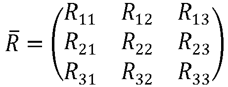
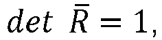


Umgekehrt kann zu einer zweidimensionalen Pixelkoordinate y in homogenen Koordinaten auf der Bildebene der Kamera anhand der Abbildungsvorschrift 
Aus der Vielzahl von Abbildungen einer Szene werden dann die Information eines 3D-Modells der Szene ohne die Brillenfassung, die Information der Position und der Lage der Brillenfassung in der Szene sowie die Information der Position der wenigstens einen Bilderfassungseinrichtung in der Szene zu einem jeden einzelnen aufgenommenen Bild, d. h. für einen jeden Zeitpunkt einer Aufnahme bestimmt. Daraus werden dann Strahlengänge durch die Brillengläser ermittelt, um aus diesen dann die lokale Brechkraft und/oder Brechkraftverteilung des linken und/oder rechten Brillenglases zu berechnen.From the multitude of images of a scene, the information of a 3D model of the scene without the spectacle frame, the information of the position and location of the spectacle frame in the scene and the information of the position of the at least one image capture device in the scene are then determined for each individual image recorded, i.e. for each point in time of a recording. From this, beam paths through the spectacle lenses are then determined in order to then calculate the local refractive power and/or refractive power distribution of the left and/or right spectacle lens.
Eine vorteilhafte Weiterbildung der Erfindung sieht deshalb vor, dass für das Berechnen der Koordinaten des wenigstens einen Strukturpunkts ein SLAM-Algorithmus verwendet wird. Auf diese Weise kann die Genauigkeit der Berechnung der Koordinaten und der Positionen der Bilderfassungseinrichtungen erhöht sowie ein Rechenaufwand für das Bestimmen der Koordinaten von wenigstens einem Strukturpunkt in einer Szene minimiert und damit die hierfür erforderliche Rechenzeit gering gehalten werden.An advantageous development of the invention therefore provides that a SLAM algorithm is used to calculate the coordinates of the at least one structural point. In this way, the accuracy of the calculation of the coordinates and the positions of the image capture devices can be increased and the computational effort for determining the coordinates of at least one structural point in a scene can be minimized, thus keeping the computing time required for this low.
Ein SLAM-Algorithmus ermöglicht insbesondere, aus Abbildungen ein- und derselben Szene, die aus verschiedenen Aufnahmepositionen erfasst sind und die deshalb die Szene aus unterschiedlichen Perspektiven zeigen, sowohl eine dreidimensionale Geometrie der Szene als auch die Positionen der wenigstens einen Bilderfassungseinrichtung zu berechnen, die diese beim Erfassen von Abbildungen der Szene jeweils eingenommen hat. Ein SLAM-Algorithmus umfasst eine Merkmalserkennungsroutine, die in der Szene vorhandene Merkmale detektiert, und eine Abgleichsroutine (Matching-Routine), mittels der für jedes Merkmal in einer Aufnahme das korrespondierende Merkmal in den aus unterschiedlichen Aufnahmepositionen aufgenommenen Bildern wiedererkannt wird. Aus den korrespondierenden Positionen jedes Merkmals in den Bildaufnahmen wird dann anhand der intrinsischen Parameter der wenigstens einen Bilderfassungseinrichtung und der zu den Aufnahmen gehörenden Positionen der Bilderfassungseinrichtungen im Raum ein dreidimensionales Modell der Szene erstellt.A SLAM algorithm makes it possible in particular to calculate both a three-dimensional geometry of the scene and the positions of the at least one image capture device that it assumed when capturing images of the scene from images of one and the same scene that are captured from different recording positions and that therefore show the scene from different perspectives. A SLAM algorithm comprises a feature recognition routine that detects features present in the scene and a matching routine that is used to recognize the corresponding feature in the images captured from different recording positions for each feature in a recording. A three-dimensional model of the scene is then created from the corresponding positions of each feature in the image recordings using the intrinsic parameters of the at least one image capture device and the positions of the image capture devices in space associated with the recordings.
Ein erfindungsgemäßes Computerprogrammprodukt enthält ein Computerprogramm mit Programmcode zur Durchführung der vorstehend angegebenen Verfahrensschritte, wenn das Computerprogramm in eine Rechnereinheit geladen und/oder in einer Rechnereinheit durchgeführt wird.A computer program product according to the invention contains a computer program with program code for carrying out the method steps specified above when the computer program is loaded into a computer unit and/or executed in a computer unit.
Eine erfindungsgemäße Vorrichtung zum Vermessen der lokalen Brechkraft und/oder der Brechkraftverteilung eines linken und/oder eines rechten Brillenglases in einer Brillenfassung enthält wenigstens eine Bilderfassungseinrichtung und eine Rechnereinheit, in die ein Computerprogramm mit Programmcode zur Durchführung der vorstehend angegebenen Verfahrensschritte geladen ist.A device according to the invention for measuring the local refractive power and/or the refractive power distribution of a left and/or a right spectacle lens in a spectacle frame contains at least one image capture device and a computer unit into which a computer program with program code for carrying out the method steps specified above is loaded.
Eine solche Vorrichtung kann insbesondere als ein Smartphone oder als ein Tablet-Computer oder auch als eine digitale Kamera ausgebildet sein. Nachfolgend werden vorteilhafte Ausführungsbeispiele der Erfindung beschrieben, die in den Zeichnungen schematisch dargestellt sind.Such a device can be designed in particular as a smartphone or as a tablet computer or even as a digital camera. Advantageous embodiments of the invention are described below, which are shown schematically in the drawings.
Die Genauigkeit eines SLAM-Algorithmus, welcher sowohl die Position und/oder die Lage der wenigstens einen Bilderfassungseinrichtung als auch die Position der Strukturpunkte in der Abbildung bestimmt, ist bevorzugt von der Kalibrierung der verwendeten wenigstens einen Bilderfassungseinrichtung bestimmt. Eine solche Kalibrierung ist in der Lage jeder Pixelkoordinate C der wenigstens einen Bilderfassungseinrichtung einen dreidimensionalen, in die jeweilige Bilderfassungseinrichtung einfallenden Lichtstrahl zuzuordnen. Mathematisch lässt sich eine solche Kalibrierung als intrinsischer Kamerakalibrierungsoperator
Mittels der vorstehend beschriebenen Kalibrierung kann der SLAM-Algorithmus jedem Strukturpunkt eine Vielzahl von dreidimensionalen, in die jeweilige Bilderfassungseinrichtung einfallenden Lichtstrahlen zuordnen, die das linke und rechte Brillenglas nicht durchsetzen. Aus diesen können dann die Koordinaten der Strukturpunkte im Raum bestimmt werden. Aus diesen Koordinaten im Raum und den Aufnahmen der Strukturpunkte, welche durch das rechte und/oder linke Brillenglas von der wenigstens einen Aufnahmeeinheit beobachtet wurden, lässt sich eine Vielzahl von Abbildungsstrahlengängen bestimmen, welche das rechte und/oder linke Brillenglas durchsetzen und nach Brechung durch das rechte und/oder linke Brillenglas den jeweiligen bekannten Strukturpunkt erreichen. Dieses so aufgespannte Strahlenmodell wird bevorzugt verwendet, um die dioptrische Wirkung oder die lokale Brechkraft oder die Brechkraftverteilung des linken und/oder rechten Brillenglases zu ermitteln.Using the calibration described above, the SLAM algorithm can assign to each structural point a plurality of three-dimensional light rays that enter the respective image capture device and do not pass through the left and right spectacle lenses. The coordinates of the structural points in space can then be determined from these. From these coordinates in space and the images of the structural points that were observed through the right and/or left spectacle lenses by the at least one recording unit, a plurality of imaging beam paths can be determined that pass through the right and/or left spectacle lenses and reach the respective known structural point after refraction through the right and/or left spectacle lenses. This ray model spanned in this way is preferably used to determine the dioptric effect or the local refractive power or the refractive power distribution of the left and/or right spectacle lenses.
Für den Fall eines regelmäßigen Musters wird durch die Aufnahme der Szene ebenfalls dessen Periodizität erfasst. Bei einer weiteren Ausführungsform der Erfindung kann aus der Interpretation der lokalen richtungsabhängigen Vergrößerung oder der lokalen richtungsabhängigen Verkleinerung des Musters durch wenigstens das rechte und/oder linke Brillenglas auf dessen lokale fokussierende Wirkung geschlossen werden. Die fokussierende Wirkung ist gemäß DIN EN ISO 13666:2013-10, Absatz 9.2, der Sammelbegriff für die sphärische und astigmatische Wirkung eines Brillenglases. Die lokale fokussierende Wirkung kann somit beispielsweise gezielt im Fern-Durchblickpunkt und/oder im Nah-Durchblickpunkt bestimmt werden. Alternativ kann durch die Bestimmung der lokalen fokussierenden Wirkung an mehreren Stellen des Brillenglases auf dessen Brechkraftverteilung zurückgeschlossen werden.In the case of a regular pattern, its periodicity is also recorded by recording the scene. In a further embodiment of the invention, the local focusing effect can be deduced from the interpretation of the local direction-dependent magnification or the local direction-dependent reduction of the pattern by at least the right and/or left lens. According to DIN EN ISO 13666:2013-10, paragraph 9.2, the focusing effect is the collective term for the spherical and astigmatic effect of a lens. The local focusing effect can thus be determined specifically in the far-vision point and/or the near-vision point, for example. Alternatively, the refractive power distribution of the lens can be deduced by determining the local focusing effect at several points on the lens.
In einem weiteren Aspekt kann das vorstehend beschriebene Verfahren zusammen mit wenigstens einem weiteren Verfahren zur Anwendung kommen. Bei diesem wenigstens einen weiteren Verfahren kann es sich um ein beispielsweise um ein Verfahren zur Bestimmung eines Refraktionsfehlers eines Auges eines Nutzers handeln, bevorzugt um ein Verfahren gemäß
- a) Darstellen eines Zeichens auf einem Bildschirm, wobei ein Parameter des auf dem Bildschirm dargestellten Zeichens verändert wird;
- b) Erfassen einer Augenbewegungsmetrik des Auges des Nutzers in Abhängigkeit von dem auf dem Bildschirm dargestellten Zeichen; und
- c) Feststellen eines Zeitpunkts, zu dem sich aus der Augenbewegungsmetrik des Auges des Nutzers eine Erkennungsschwelle des Nutzers für das auf dem Bildschirm dargestellte Zeichen ergibt; und
- d) Bestimmen eines Wertes für den Refraktionsfehler des Auges des Nutzers aus dem zu dem Zeitpunkt festgelegten Parameter.
- (a) displaying a character on a screen while changing a parameter of the character displayed on the screen;
- b) capturing an eye movement metric of the user’s eye as a function of the character displayed on the screen; and
- (c) determining a point in time at which the eye movement metric of the user’s eye results in a user recognition threshold for the character displayed on the screen; and
- d) Determining a value for the refractive error of the user’s eye from the parameter determined at that time.
Alternativ oder zusätzlich zu dem vorstehend beschriebenen Verfahren kann es sich bei dem wenigstens einen weiteren Verfahren beispielsweise auch um ein Verfahren zur Bestimmung mindestens eines optischen Parameters eines Brillenglases handeln, bevorzugt um ein Verfahren gemäß der europäischen Patentanmeldung mit dem Anmeldungsaktenzeichen
- a) Aufnehmen eines Bildes unter Verwendung eines Brillenglases; und
- b) Ermitteln mindestens eines optischen Parameters des Brillenglases mittels Bildverarbeitung des Bildes, wobei das Bild eine die Augen einschließende Augenpartie und/oder eine an die Augen angrenzende Gesichtspartie eines Nutzers des Brillenglases umfasst.
- a) taking a picture using a spectacle lens; and
- b) determining at least one optical parameter of the spectacle lens by means of image processing of the image, wherein the image comprises an eye area including the eyes and/or a facial area adjacent to the eyes of a user of the spectacle lens.
Alternativ oder zusätzlich zu den vorstehend beschriebenen Verfahren kann es sich bei dem wenigstens einen zusätzlichen Verfahren auch um ein Verfahren zur Bestimmung eines Refraktionsfehlers eines Auges eines Nutzers handeln, bevorzugt um ein Verfahren gemäß der europäischen Patentanmeldung mit dem Anmeldungsaktenzeichen
- a) Darstellen eines Zeichens auf einem Bildschirm, wobei ein Parameter des auf dem Bildschirm dargestellten Zeichens verändert wird;
- b) Erfassen einer Reaktion des Nutzers in Abhängigkeit von dem auf dem Bildschirm dargestellten Zeichen;
- c) Feststellen eines Zeitpunkts, zu dem sich aus der Reaktion des Nutzers eine Erkennbarkeit des auf dem Bildschirm dargestellten Zeichens für den Nutzer ergibt; und
- d) Bestimmen eines Wertes für den Refraktionsfehler des Auges des Nutzers aus dem zu dem Zeitpunkt festgelegten Parameter, wobei das auf dem
- (a) displaying a character on a screen while changing a parameter of the character displayed on the screen;
- b) detecting a user reaction in response to the character displayed on the screen;
- (c) determining a point in time at which the user’s reaction results in the character displayed on the screen being recognisable to the user; and
- d) determining a value for the refractive error of the user’s eye from the parameter determined at that time, wherein the
Bildschirm dargestellte Zeichen ein periodisches Muster ist, wobei der Parameter des auf dem Bildschirm dargestellten Musters mindestens eine Ortsfrequenz umfasst, und der Wert für den Refraktionsfehler aus der zu dem Zeitpunkt festgelegten Ortsfrequenz des Musters bestimmt wird.The character displayed on the screen is a periodic pattern, the parameter of the pattern displayed on the screen comprising at least one spatial frequency, and the value for the refractive error is determined from the spatial frequency of the pattern determined at that time.
Alternativ oder zusätzlich zu den vorstehend beschriebenen Verfahren ist als wenigstens ein zusätzliches Verfahren auch ein Verfahren zur Bestimmung der Brechkraftverteilung eines Brillenglases möglich, bevorzugt ein Verfahren gemäß der europäischen Patentanmeldung mit dem Anmeldungsaktenzeichen
In einer übergeordneten Anwendung können die verschiedenen vorstehend beschriebenen Verfahren, d. h. das erfindungsgemäße Verfahren sowie das wenigstens eine weitere Verfahren, kombiniert werden, um beispielsweise aus einem Vergleich der jeweils erhaltenen Ergebnisse eine höhere Genauigkeit oder eine Plausibiltätsüberprüfung der in den einzelnen Verfahren erhaltenen Ergebnisse zu erhalten. Die verschiedenen vorstehend beschriebenen Verfahren können nacheinander oder gleichzeitig in der übergeordneten Anwendung erfolgen. Erfolgen die verschiedenen Verfahren nacheinander kann deren Reihenfolge unabhängig voneinander sein und/oder es kann sich um eine beliebige Reihenfolge handeln. Erfolgen die verschiedenen Verfahren nacheinander kann es bevorzugt sein, wenigstens eines der erfindungsgemäßen Verfahren zur Bestimmung der Brechkraftverteilung zuletzt durchzuführen. Eine übergeordnete Anwendung kann beispielsweise ein die verschiedenen Verfahren umfassendes Computerprogramm sein.In a higher-level application, the various methods described above, ie the method according to the invention and the at least one further method, can be combined in order to achieve, for example, a higher accuracy or a plausibility check of the results obtained in the individual methods from a comparison of the results obtained in each case. results. The various methods described above can be carried out one after the other or simultaneously in the higher-level application. If the various methods are carried out one after the other, their order can be independent of one another and/or they can be in any order. If the various methods are carried out one after the other, it can be preferable to carry out at least one of the methods according to the invention for determining the refractive power distribution last. A higher-level application can be, for example, a computer program comprising the various methods.
- Fig. 1Fig. 1
- eine Szene mit einer Brillenfassung und mit einer Bilderfassungseinrichtung, die in unterschiedlichen Aufnahmepositionen angeordnet ist;a scene with a pair of spectacle frames and with an image capture device arranged in different recording positions;
- Fig. 2Fig. 2
- einen Ausschnitt einer mittels der Bilderfassungseinrichtung in einer ersten Aufnahmeposition erfassten ersten Abbildung der Szene;a section of a first image of the scene captured by the image capture device in a first recording position;
- Fig. 3Fig. 3
- einen Ausschnitt einer zweiten mittels der Bilderfassungseinrichtung in einer von der ersten Aufnahmeposition verschiedenen weiteren Aufnahmeposition erfassten Abbildung der Szene;a section of a second image of the scene captured by the image capture device in a further recording position different from the first recording position;
- Fig. 4Fig. 4
- ein Koordinatensystem der Szene und ein Koordinatensystem der Bilderfassungseinrichtung mit einem Brillenglas;a coordinate system of the scene and a coordinate system of the image capture device with a spectacle lens;
- Fig. 5Fig. 5
- ein Strahlenmodell einer Brillenfassung bei Beobachten der Szene aus zwei unterschiedlichen Perspektiven;a ray model of a spectacle frame when observing the scene from two different perspectives;
- Fig. 6Fig. 6
- eine aus dem Strahlenmodell der Brillenfassung berechnete Brechkraftverteilung;a refractive power distribution calculated from the ray model of the spectacle frame;
- Fig. 7Fig. 7
- ein Flussdiagramm einer Ausgestaltung eines Verfahrens zum Vermessen eines linken und/oder rechten Brillenglases in einer Brillenfassung;a flow chart of an embodiment of a method for measuring a left and/or right spectacle lens in a spectacle frame;
- Fig. 8Fig. 8
- ein Flussdiagramm einer weiteren Ausgestaltung eines Verfahrens zum Vermessen eines linken und/oder rechten Brillenglases in einer Brillenfassung;a flow chart of a further embodiment of a method for measuring a left and/or right spectacle lens in a spectacle frame;
- Fig. 9Fig. 9
- eine weitere Szene mit einer Brillenfassung und mit einer Bilderfassungseinrichtung, die in unterschiedlichen Aufnahmepositionen angeordnet ist;another scene with a pair of glasses and with an image capture device arranged in different recording positions;
- Fig. 10Fig. 10
- eine weitere Szene ohne die Brillenfassung mit der Bilderfassungseinrichtung;another scene without the spectacle frame with the image capture device;
- Fig. 11Fig. 11
- eine weitere Szene mit einer Brillenfassung und mit einer Bilderfassungseinrichtung, die in unterschiedlichen Aufnahmepositionen angeordnet ist;another scene with a pair of glasses and with an image capture device arranged in different recording positions;
- Fig. 12Fig. 12
- einen Ausschnitt der mittels der Bilderfassungseinrichtung in der ersten Aufnahmeposition erfassten Abbildung der Szene;a section of the image of the scene captured by the image capture device in the first recording position;
- Fig. 13Fig. 13
- eine weitere Szene ohne die Brillenfassung mit der Bilderfassungseinrichtung; undanother scene without the spectacle frame with the image capture device; and
- Fig. 14Fig. 14
- einen Ausschnitt der mittels der Bilderfassungseinrichtung erfassten Abbildung der Szene ohne die Brillenfassung.a section of the image of the scene captured by the image capture device without the spectacle frame.
Die
Um die lokale Brechkraft des linken und rechten Brillenglases 20, 22 in der Brille 16 zu vermessen, wird die Szene 10 mittels der Kamera 28 in einer als ein Smartphone ausgebildeten Bilderfassungseinrichtung 30 in einer Vielzahl unterschiedlicher Aufnahmepositionen 32, 34, 36, ... aufgenommen, indem ein Benutzer das in den Videomodus geschaltete Smartphone mit einer Hand hält und dabei entlang einer Trajektorie 38 verlagert. Der Benutzer erfasst damit die Szene 10 mittels der Kamera 28 der Bilderfassungseinrichtung 30 aus unterschiedlichen Perspektiven. Für das Verarbeiten der mittels der Kamera 28 erfassten Aufnahmen der Szene 10 enthält die Bilderfassungseinrichtung 30 eine Rechnereinheit 40.In order to measure the local refractive power of the left and
Die
Bei dem Verlagern der Bilderfassungseinrichtung 30 relativ zu der Szene 10 werden, wie sich aus der
Die
Die
Um das in der
Aus der Pixelkoordinate in homogenen Koordinaten 


From the pixel coordinate to homogeneous coordinates
Durch das Detektieren und Verfolgen von ortsfesten, zeitinvarianten Strukturpunkten 26, deren Abbildungsstrahlengänge nicht durch die Brillengläser hindurch verlaufen, über mehrere Aufnahmen an verschiedenen Aufnahmepositionen 32, 34, 36 hinweg mittels Feature-Matching-Algorithmen kann für einen jeden dieser Strukturpunkte 26 aus den intrinsischen Parametern der Bilderfassungseinrichtung sowie der Lage und Position einer Bilderfassungseinrichtung zum Zeitpunkt des Erfassens einer Abbildung damit auf deren Lage in der Szene 10 in dem Koordinatensystem 46 der Bilderfassungseinrichtung 30 geschlossen werden.By detecting and tracking stationary, time-invariant
Aus einem jeden abgebildeten Strukturpunkt 26 wird dann ein Hauptstrahl 53, 53', der ein Brillenglas 20, 22 der Brille 16 durchsetzt, entsprechend der Position der Bilderfassungseinrichtung 30 berechnet. Hieraus und aus der 3D-Koordinate des Punktes ergibt sich dann ein Strahlenmodell, das verschiedene Durchblickbedingungen derselben Brille 16 in derselben Szene 10 wiederspiegelt und das Abbildungsstrahlen, die abgelenkt werden und die verschiedenen Lagen und Positionen einer Bilderfassungseinrichtung entsprechen, beschreibt.From each imaged
Über einen sogenannten inversen Ansatz ist es dann möglich, aus diesem Datensatz sowohl die Position als auch die Form und Lage sowie den Brechungsindex des Materials des linken und rechten Brillenglases 20, 22 in der Brillenfassung 18 der Brille 16 zu bestimmen und damit auch deren optische Wirkung für einen Brillenträger.Using a so-called inverse approach, it is then possible to determine from this data set both the position and the shape and location as well as the refractive index of the material of the left and
Ein inverser Ansatz ist eine Umkehrung der sogenannten Vorwärtsrechnung, bei der in einer optischen Strahldurchrechnung, die auch als Raytracing bezeichnet wird, der Verlauf von Lichtstrahlen durch ein optisches System bestehend aus bekannten optischen Grenzflächen und bekannten Brechungsindizes zwischen den Grenzflächen berechnet wird. Vorausgesetzt, dass die Grenzflächen, deren Normalen und die Brechungsindizes bekannt sind, ist es damit möglich, einen jeden Lichtstrahl durch das System eindeutig zu berechnen. Im Falle des inversen Ansatzes wird dabei eine optische Grenzfläche oder ein Brechungsindex gesucht, die bzw. der zu einer gegebenen Anzahl von Lichtstrahlen passt. Um eine Fehlergröße zu bestimmen, wird die Vorwärtsrechnung anhand der mittels des inversen Ansatzes bestimmten Fläche durchgeführt und es wird dann ein Vergleich von Strahlpunkten vor und/oder hinter der jeweiligen Grenzfläche erstellt. Durch Variation der zu bestimmenden Fläche wird dann gezielt mittels eines Optimierungsverfahrens die Fehlergröße minimiert. Alternativ zu reinen Optimierungsverfahren, die durch Parametervariationen das Minimum einer Fehlerfunktion ermitteln können, ist es auch möglich, hier sogenannte Lichtpfad-Triangulationsverfahren zum Einsatz zu bringen, die auch in Kombination mit einem Optimierungsverfahren genutzt werden. Derartige Verfahren sind z. B. in der vorstehend erwähnten Publikation "K.N. Kutukalos und E. Steger, A Theory of Refractive and specular 3D Shape by Light-Path Triangulation, University of Toronto" beschrieben.An inverse approach is a reversal of the so-called forward calculation, in which the course of light rays through an optical system consisting of known optical interfaces and known refractive indices between the interfaces is calculated in an optical ray calculation, which is also known as ray tracing. Provided that the interfaces, their normals and the refractive indices are known, it is possible to calculate each light ray through the system unambiguously. In the case of the inverse approach, an optical interface or refractive index is sought that matches a given number of light rays. In order to determine an error size, the forward calculation is carried out using the area determined using the inverse approach and a comparison is then made of ray points in front of and/or behind the respective interface. By varying the area to be determined, the error size is then specifically minimized using an optimization process. As an alternative to pure optimization methods, which can determine the minimum of an error function through parameter variations, it is also possible to use so-called light path triangulation methods, which can also be used in combination with an optimization method. Such methods are described, for example, in the above-mentioned publication "K.N. Kutukalos and E. Steger, A Theory of Refractive and specular 3D Shape by Light-Path Triangulation, University of Toronto".
Die dioptrische Wirkung der Brillengläser kann, wenn deren Form und Brechungsindex bekannt ist, insbesondere durch eine Vorwärtsrechnung von Strahlenbündeln berechnet werden. Der Scheitelbrechwert eines Brillenglases kann z. B. bestimmt werden, indem ein paralleles Strahlenbündel, dessen Durchmesser etwa 5 mm beträgt und das damit der Größe der Augenpupille entspricht, so durch das Brillenglas propagiert wird, dass dessen Hauptstrahl, d. h. dessen optische Achse augenseitig das Brillenglas senkrecht verlässt. Der Wert des Scheitelbrechwertes ist dann der Kehrwert des Abstands der Brillenglasfläche, aus welcher der Hauptstrahl austritt, zu dem Punkt der kleinsten Strahltaille oder Ausdehnung des Strahlenbündels.The dioptric power of the lenses can be calculated, if their shape and refractive index are known, in particular by forward calculation of beams of rays. The vertex power of a lens can be determined, for example, by propagating a parallel beam of rays, the diameter of which is about 5 mm and thus corresponds to the size of the eye's pupil, through the lens in such a way that its main ray, ie its optical axis, leaves the lens perpendicularly on the eye side. The value of the vertex power is then the reciprocal of the distance from the surface of the lens from which the main ray emerges to the point of the smallest beam waist or extension of the beam of rays.
Bei Brillengläsern umfassend wenigstens eine torische Wirkung weist die richtungsabhängige Ausdehnung des Strahlenbündels zwei Minima auf. Der Abstand dieser beiden Minima zu der Oberfläche des Brillenglases beschreibt die Wirkung der beiden Hauptschnitte. Die Differenz dieser beiden Hauptschnitte beschreibt die zylindrische Wirkung des Brillenglases. Die gesamte Ablenkung des Hauptstrahles durch das Brillenglas ist als prismatische Wirkung des Brillenglases an der jeweiligen Stelle zu betrachten.In the case of lenses comprising at least one toric effect, the direction-dependent expansion of the beam of rays has two minima. The distance between these two minima and the surface of the lens describes the effect of the two main sections. The difference between these two main sections describes the cylindrical effect of the lens. The entire deflection of the main ray by the lens is to be regarded as the prismatic effect of the lens at the respective point.
Für die Umrechnung von Pixelkoordinaten C der Kamera 28 in der Bilderfassungseinrichtung 30 zu dem Strahlvektor eines Abbildungsstrahlengangs dient der sogenannte intrinsische Kamerakalibrierungsoperator
In der
Die
In einem ersten Schritt S1 wird wenigstens eine erste Abbildung einer Szene 10 mit einer Vielzahl von Strukturpunkten 26 und mit einem linken und/oder einem rechten Brillenglas 20, 22 in einer Brille 16 und mit einem ein Koordinatensystem 44 der Brillenfassung 18 der Brille 16 definierenden Abschnitt der Brillenfassung 18 der Brille 16 mittels einer Bilderfassungseinrichtung 30 mit einem Abbildungsstrahlengang für Strukturpunkte 26 erfasst, der das erste und/oder das zweite Brillenglas 20, 22 der Brille 16 durchsetzt.In a first step S1, at least a first image of a
In einem auf den Schritt S1 folgenden Schritt S2 werden dann wenigstens zwei weitere Abbildungen der Szene 10 ohne das erste und/oder das zweite Brillenglas 20, 22 der Brille 16 mit den in der ersten Abbildung abgebildeten Strukturpunkten 26 mittels der Bilderfassungseinrichtung 30 erfasst.In a step S2 following step S1, at least two further images of the
In einem Schritt S3 erfolgt dann das Berechnen der Koordinaten der ortsfesten, zeitinvarianten Strukturpunkte 26 in dem zu dem Koordinatensystem 46 der Bilderfassungseinrichtung 30 in den unterschiedlichen Aufnahmepositionen referenzierten Koordinatensystem 25 der Szene 10 aus den wenigstens zwei weiteren Abbildungen der Szene 10 mittels Bildauswertung.In a step S3, the coordinates of the stationary, time-invariant structure points 26 in the coordinate
In einem auf den Schritt S3 folgenden Schritt S4 wird dann die Brechkraftverteilung k(x, y) für wenigstens einen Abschnitt des linken Brillenglases 20 in dem zu dem Koordinatensystem 25 der Szene 10 referenzierten Koordinatensystem 44 der Brillenfassung 18 bestimmt und/oder es wird die Brechkraftverteilung k(x, y) für wenigstens einen Abschnitt des rechten Brillenglases 22 in einem zu dem Koordinatensystem 44 der Brillenfassung 18 referenzierten Koordinatensystem 25 der Szene 10 aus den Koordinaten der ortsfestes, zeitinvarianten Strukturpunkte 26 und dem Bild der Strukturpunkte 26 in der wenigstens einen ersten Abbildung der Szene 10 bestimmt.In a step S4 following step S3, the refractive power distribution k(x, y) is then determined for at least one section of the
Die
Auch hier wird wiederum in einem ersten Schritt S1, wie in der
Wie in der
In einem auf den Schritt S1 folgenden Schritt S2 wird dann, wie in der
In einem Schritt S3 wird das Koordinatensystem 25 der Szene 10 zu dem Koordinatensystem 44 der Brillenfassung 18 referenziert und es werden dann die Koordinaten der Strukturpunkte 26 in dem zu dem Koordinatensystem 46 der Bilderfassungseinrichtung 30 in den unterschiedlichen Aufnahmepositionen referenzierten Koordinatensystem 25 der Szene 10 aus der wenigstens einen weiteren Abbildung der Szene 10 mittels Bildauswertung berechnet.In a step S3, the coordinate
Darauf wird in einem Schritt S4 die Brechkraftverteilung k(x,y) für wenigstens einen Abschnitt des linken Brillenglases 20 in dem zu dem Koordinatensystem 25 der Szene 10 referenzierten Koordinatensystem 44 der Brillenfassung 18 bestimmt und/oder es wird die Brechkraftverteilung k(x, y) für wenigstens einen Abschnitt des rechten Brillenglases 22 in dem Koordinatensystem 44 der Brillenfassung 18 aus den Koordinaten der Strukturpunkte 26 und dem Bild der Strukturpunkte 26 in der wenigstens einen ersten Abbildung der Szene 10 bestimmt.Then, in a step S4, the refractive power distribution k(x,y) is determined for at least one section of the
Wie die
Dann wird, wie in der
Weil sich Strukturpunkte 26 in der Szene 10, die in der
Es kann vorgesehen sein, die Nachbarschaftsbeziehungen zwischen den Strukturpunkten 26 in der Szene 10 auszuwerten, um eine Verlagerung von Strukturpunkten 26 in einem Koordinatensystem 25 der Szene 10 zu erkennen und die Koordinaten von in einer Szene 10 verlagerten Strukturpunkten 26 bei dem Bestimmen der Brechkraftverteilung für wenigstens einen Abschnitt des rechten Brillenglases 22 und des linken Brillenglases 20 in dem Koordinatensystem 44 der Brillenfassung 18 nicht zu berücksichtigen, damit Bewegungen von Strukturpunkten 26 in der Szene 10 das Messergebnis für die lokale Brechkraft des linken und rechten Brillenglases 20, 22 nicht verfälschen.It can be provided to evaluate the neighborhood relationships between the
Zusammenfassend ist insbesondere folgendes festzuhalten: Die Erfindung betrifft ein Verfahren zum Vermessen der lokalen Brechkraft oder der Brechkraftverteilung eines linken und/oder eines rechten Brillenglases 20, 22 in einer Brillenfassung 18. Dabei wird wenigstens eine erste Abbildung einer Szene 10 mit zumindest einem Strukturpunkt 26 und mit einem linken und/oder einem rechten Brillenglas 20, 22 in einer Brillenfassung 18 mittels einer Bilderfassungseinrichtung 30 aus wenigstens einer ersten Aufnahmeposition 32 mit wenigstens einem Abbildungsstrahlengang für Strukturpunkte 26 erfasst, der das erste und/oder das zweite Brillenglas 20, 22 in der Brillenfassung 18 durchsetzt. Es werden wenigstens zwei weitere Abbildungen der Szene 10 ohne das erste und/oder das zweite Brillenglas 20, 22 der Brillenfassung 18 oder ohne die Brillenfassung enthaltend das linke und/oder das rechte Brillenglas mit den in der ersten Abbildung abgebildeten Strukturpunkten 26 mittels der Bilderfassungseinrichtung 30 aus wenigstens zwei verschiedenen Aufnahmepositionen 32, 34, 36, von denen eine zu der ersten Aufnahmeposition identisch sein kann, erfasst und es werden die Koordinaten der Strukturpunkte 26 in einem Koordinatensystem 25 aus den wenigstens zwei weiteren Abbildungen der Szene 10 mittels Bildauswertung berechnet, oder es werden wenigstens zwei weitere Abbildungen der Szene 10 mit dem linken und/oder dem rechten Brillenglas 20, 22 mittels einer Bilderfassungseinrichtung 30 aus wenigstens zwei von der ersten Aufnahmeposition verschiedenen weiteren Aufnahmepositionen mit wenigstens einem Abbildungsstrahlengang für die in der ersten Abbildung abgebildeten Strukturpunkte 26 erfasst, der das erste und/oder das zweite Brillenglas 20, 22 der Brillenfassung 18 nicht durchsetzt, um dann eine Brechkraftverteilung k(x,y) für wenigstens einen Abschnitt des linken Brillenglases 20 in einem zu dem Koordinatensystem 44 der Brillenfassung 18 referenzierten Koordinatensystem 25 der Szene 10 und/oder eine Brechkraftverteilung k(x,y) für wenigstens einen Abschnitt des rechten Brillenglases 22 in einem Koordinatensystem 25 aus den Koordinaten der Strukturpunkte 26 und dem Bild der Strukturpunkte 26 in der wenigstens einen ersten Abbildung der Szene 10 zu bestimmen.In summary, the following should be noted in particular: The invention relates to a method for measuring the local refractive power or the refractive power distribution of a left and/or a
- 1010
- Szenescene
- 1212
- TischTable
- 1414
- Tischdecketablecloth
- 1616
- BrilleGlasses
- 1818
- Brillenfassungeyeglass frame
- 2020
- linkes Brillenglasleft lens
- 2222
- rechtes Brillenglasright lens
- 2424
- Gegenständeobjects
- 2525
- Koordinatensystem der Szenecoordinate system of the scene
- 25'25'
- Koordinatensystem der Szene nach Translationcoordinate system of the scene after translation
- 2626
- Strukturpunktstructural point
- 26'26'
- Abbildungen von StrukturpunktImages of structure point
- 2727
- MusterPattern
- 2828
- Kameracamera
- 3030
- Bilderfassungseinrichtungimage capture device
- 32, 34, 3632, 34, 36
- Aufnahmepositionrecording position
- 3838
- Trajektorietrajectory
- 4040
- Rechnereinheitcomputer unit
- 4242
- Ausschnittneckline
- 4444
- Koordinatensystem der Fassungcoordinate system of the frame
- 4646
- Koordinatensystem Bilderfassungseinrichtungcoordinate system image acquisition device
- 4848
- linkes Augeleft eye
- 5050
- rechtes Augeright eye
- 5252
- Graphgraph
- 53, 53'53, 53'
- Hauptstrahlmain beam
- 5454
- Flussdiagrammflow chart
- CC
- Pixelkoordinatepixel coordinate
- KK
- Kamerakalibrierungsoperatorcamera calibration operator
- RR
- Rotationsoperatorrotation operator
- TT
- Translationsoperatortranslation operator
- S1,S2,S3,S4S1,S2,S3,S4
- SchrittStep
- k(x,y)k(x,y)
- lokale Brechkraft bzw. Brechkraftverteilunglocal refractive power or refractive power distribution
Claims (15)
- Method for measuring the local refractive power of a left and/or a right spectacle lens (20, 22) in a spectacle frame (18),including a step of capturing at least one first image representation of a scene (10) with many structure points (26) and with a left and/or a right spectacle lens (20, 22) in the spectacle frame (18) by means of at least one image capture device (30) from at least one first recording position (32) with at least an imaging beam path for each of these structure points (26), said imaging beam path passing through the left and/or the right spectacle lens (20, 22),including a step of capturing at least two further image representations of the scene (10) without the left and/or the right spectacle lens (20, 22) of the spectacle frame (18) or without the spectacle frame (18) containing the left and/or the right spectacle lens (20, 22) with the structure points (26) imaged in the first image representation by means of the at least one image capture device (30) from at least two different recording positions (32, 34, 36), one of which can be identical to the first recording position (32); andincluding a step of calculating the coordinates of the structure points (26) in a coordinate system (25) from the at least two further image representations of the scene (10) by means of image evaluation by means of triangulation,characterized bya step of determining a local refractive power of the left spectacle lens (20) and/or of the right spectacle lens (22) from the coordinates of the structure points (26) and the image of the structure points (26) in the at least one first image representation of the scene (10) by means of an inverted approach, in which the optical interfaces of the left and/or right spectacle lens (20, 22) are calculated from the imaging beam paths for the structure points (26) by virtue of the variation of the interface to be determined in each case leading to a minimization of an error term, the error term being determined for the interface by virtue of ray tracing being used to create a comparison of beam points upstream and downstream of the interface.
- Method for measuring the local refractive power of a left and/or a right spectacle lens (20, 22) in a spectacle frame (18),including a step of capturing at least one first image representation of a scene (10) with many structure points (26) and with a left and/or a right spectacle lens (20, 22) in the spectacle frame (18) by means of at least one image capture device (30) from at least one first recording position (32) with at least an imaging beam path for each of these structure points (26), said imaging beam path passing through the left and/or the right spectacle lens (20, 22),including a step of capturing at least two further image representations of the scene (10) with the left and/or the right spectacle lens (20, 22) by means of at least one image capture device (30) from at least two different further recording positions (34, 36), which differ from the first recording position (32) and which each have at least one imaging beam path for the structure points (26) captured in the first image representation, said imaging beam paths not passing through the left and the right spectacle lens (20, 22) of the spectacle frame (18); andincluding a step of calculating the coordinates of the structure points (26) from the at least two further image representations of the scene (10) by means of image evaluation by means of triangulation,characterized bya step of determining a local refractive power of the left spectacle lens (20) and/or of the right spectacle lens (22) from the coordinates of the structure points (26) and the image of the structure points (26) in the at least one first image representation of the scene (10) by means of an inverted approach, in which the optical interfaces of the left and/or right spectacle lens (20, 22) are calculated from the imaging beam paths for the structure points (26) by virtue of the variation of the interface to be determined in each case leading to a minimization of an error term, the error term being determined for the interface by virtue of ray tracing being used to create a comparison of beam points upstream and downstream of the interface.
- Method according to Claim 1 or 2, characterized by capturing a multiplicity of first image representations of the scene (10) and a multiplicity of further image representations of the scene (10), wherein the coordinates of the structure points (26) in the coordinate system (25) are calculated from the multiplicity of further image representations of the scene (10).
- Method according to any of Claims 1-3, characterized in that the scene (10) contains a left eye (48) and/or right eye (50) of a spectacle wearer of the spectacle frame (18).
- Method according to Claim 4, characterized in that the image capture device (30) is used to capture a multiplicity of image representations of the scene (10) with a displacement of the image capture device (30), wherein the left eye (48) and/or the right eye (50) of the wearer of the spectacle frame (18) gazes at the displaced image capture device (30) and viewing beam paths for different viewing directions of the left eye (48) and/or right eye (50) of the wearer of the spectacle frame (18) through the left spectacle lens (20) and/or the right spectacle lens (22) of the spectacle frame (18) are calculated from the multiplicity of image representations of the scene (10) captured in the process and a local refractive power k(x, y) of the left spectacle lens (20) and/or of the right spectacle lens (22) is determined for each viewing direction therethrough.
- Method according to any of Claims 1 to 5, characterized in that a SLAM algorithm is used to calculate intrinsic parameters of the at least one image capture device (30).
- Method according to Claim 6, characterized by intrinsic parameters from the group of focal length, image centre, shearing parameters, scaling parameters, distortion parameters.
- Method according to any of Claims 1 to 7, characterized in that a SLAM algorithm is used to calculate the coordinates of the structure points (26) and/or the recording positions (32, 34, 36) of the at least one image capture device (30) in the coordinate system (25); and/or in that the coordinates of at least some of the structure points (26) in the scene (10) are invariant; and/or in that the coordinates of the structure points (26) are calculated in a coordinate system (25) by evaluating displacements between the image representations of the structure points (26) in the scene (10) from different recording positions (32, 34, 36).
- Method according to any of Claims 1 to 8, characterized in that a displacement of structure points (26) in a coordinate system (25) is recognized by evaluating proximity relations between the structure points (26) in the scene (10), and the coordinates of structure points (26) displaced in a scene (10) are not taken into account when determining a refractive power distribution k(x,y) for at least one section of the right spectacle lens (22) and/or the left spectacle lens (20).
- Method for measuring the refractive power distribution k(x,y) of a left and/or a right spectacle lens (20, 22) in a spectacle frame (18), wherein a local refractive power of the left and/or right spectacle lens (20, 22) is measured according to any of Claims 1 to 9 at a plurality of different locations on the left and/or right spectacle lens (20, 22).
- Computer program product comprising a computer program having program code for carrying out all method steps which are specified in any of Claims 1 to 10 when the computer program is loaded on a computer unit of an apparatus according to Claim 12 and/or executed on a computer unit of an apparatus according to Claim 12.
- Apparatus for measuring the local refractive power of a left and/or a right spectacle lens (20, 22) in a spectacle frame (18), comprising an image capture device (30) and comprising a computer unit (40), loaded onto which is a computer program with program code for carrying out all method steps specified in any of Claims 1 to 9, or for measuring the refractive power distribution of a left and/or a right spectacle lens (20, 22) in a spectacle frame (18), comprising an image capture device (30) and comprising a computer unit (40), loaded onto which is a computer program with program code for carrying out all method steps specified in Claim 10.
- Apparatus according to Claim 12, embodied as a smartphone or as a tablet computer or as a camera (28).
- Computer-readable data medium, on which the computer program product according to Claim 11 is stored.
- Data medium signal, which transmits the computer program according to Claim 11.
Applications Claiming Priority (3)
| Application Number | Priority Date | Filing Date | Title |
|---|---|---|---|
| EP19170715.7A EP3730919A1 (en) | 2019-04-23 | 2019-04-23 | Method and device for measuring the local refractive power or refractive power distribution of a spectacle lens |
| PCT/EP2020/061238 WO2020216799A1 (en) | 2019-04-23 | 2020-04-22 | Method and device for measuring the local refractive power and/or refractive power distribution of a spectacle lens |
| EP20723300.8A EP3959497B1 (en) | 2019-04-23 | 2020-04-22 | Method and device for measuring the local refractive power or refractive power distribution of a spectacle lens |
Related Parent Applications (2)
| Application Number | Title | Priority Date | Filing Date |
|---|---|---|---|
| EP20723300.8A Division-Into EP3959497B1 (en) | 2019-04-23 | 2020-04-22 | Method and device for measuring the local refractive power or refractive power distribution of a spectacle lens |
| EP20723300.8A Division EP3959497B1 (en) | 2019-04-23 | 2020-04-22 | Method and device for measuring the local refractive power or refractive power distribution of a spectacle lens |
Publications (3)
| Publication Number | Publication Date |
|---|---|
| EP3982102A1 EP3982102A1 (en) | 2022-04-13 |
| EP3982102C0 EP3982102C0 (en) | 2024-10-16 |
| EP3982102B1 true EP3982102B1 (en) | 2024-10-16 |
Family
ID=66251606
Family Applications (3)
| Application Number | Title | Priority Date | Filing Date |
|---|---|---|---|
| EP19170715.7A Withdrawn EP3730919A1 (en) | 2019-04-23 | 2019-04-23 | Method and device for measuring the local refractive power or refractive power distribution of a spectacle lens |
| EP21209645.7A Active EP3982102B1 (en) | 2019-04-23 | 2020-04-22 | Method and device for measuring the local refractive power and/or refractive power distribution of a spectacle lens |
| EP20723300.8A Active EP3959497B1 (en) | 2019-04-23 | 2020-04-22 | Method and device for measuring the local refractive power or refractive power distribution of a spectacle lens |
Family Applications Before (1)
| Application Number | Title | Priority Date | Filing Date |
|---|---|---|---|
| EP19170715.7A Withdrawn EP3730919A1 (en) | 2019-04-23 | 2019-04-23 | Method and device for measuring the local refractive power or refractive power distribution of a spectacle lens |
Family Applications After (1)
| Application Number | Title | Priority Date | Filing Date |
|---|---|---|---|
| EP20723300.8A Active EP3959497B1 (en) | 2019-04-23 | 2020-04-22 | Method and device for measuring the local refractive power or refractive power distribution of a spectacle lens |
Country Status (8)
| Country | Link |
|---|---|
| US (1) | US11982878B2 (en) |
| EP (3) | EP3730919A1 (en) |
| JP (1) | JP7126031B2 (en) |
| KR (1) | KR102444768B1 (en) |
| CN (1) | CN113711003B (en) |
| ES (1) | ES2933452T3 (en) |
| IL (1) | IL287469B2 (en) |
| WO (1) | WO2020216799A1 (en) |
Families Citing this family (7)
| Publication number | Priority date | Publication date | Assignee | Title |
|---|---|---|---|---|
| EP3730037A1 (en) | 2019-04-23 | 2020-10-28 | Carl Zeiss Vision International GmbH | Determination of a refraction error of an eye |
| EP3730918A1 (en) | 2019-04-23 | 2020-10-28 | Carl Zeiss Vision International GmbH | Method and device for measuring the local refractive power and/or refractive power distribution of a spectacle lens |
| EP3730998A1 (en) | 2019-04-23 | 2020-10-28 | Carl Zeiss Vision International GmbH | Determination of at least one optical parameter of a spectacle lens |
| US12247826B2 (en) * | 2021-06-11 | 2025-03-11 | Optinno BV | Spectacle lens shape measurement method |
| CN114112328A (en) * | 2021-12-13 | 2022-03-01 | 上海理工大学 | Lens diopter measuring device and method |
| EP4361704B1 (en) * | 2022-10-27 | 2026-07-01 | Pupil Labs GmbH | EYE-TRACKING MODULE AND HEAD-WEARABLE DEVICE |
| EP4443219A1 (en) * | 2023-04-03 | 2024-10-09 | Carl Zeiss Vision International GmbH | Apparatus and method suitable for scanning a spectacle frame |
Family Cites Families (18)
| Publication number | Priority date | Publication date | Assignee | Title |
|---|---|---|---|---|
| US3880525A (en) * | 1974-05-08 | 1975-04-29 | American Optical Corp | Method and apparatus for determining the refractive characteristics of a lens |
| JPS5690233A (en) * | 1979-12-24 | 1981-07-22 | Asahi Optical Co Ltd | Automatic lens meter |
| JP4086429B2 (en) * | 1998-10-12 | 2008-05-14 | Hoya株式会社 | Evaluation method and apparatus for spectacle lens |
| KR20010061557A (en) * | 1999-12-28 | 2001-07-07 | 박종섭 | Semiconductor memory device and method for forming the same |
| KR20060093596A (en) * | 2005-02-22 | 2006-08-25 | 엘지전자 주식회사 | How to measure diopter of mobile terminal |
| JP5107359B2 (en) * | 2007-08-31 | 2012-12-26 | Hoya株式会社 | Progressive power lens evaluation method and evaluation apparatus, and progressive power lens manufacturing method |
| FR2984565A1 (en) * | 2011-12-19 | 2013-06-21 | Thomson Licensing | METHOD AND DEVICE FOR ESTIMATING THE OPTICAL POWER OF LENSES OF CORRECTIVE GLASSES OF A PAIR OF LENSES CARRIED BY A SPECTATOR. |
| JP6307805B2 (en) | 2013-07-24 | 2018-04-11 | 富士通株式会社 | Image processing apparatus, electronic device, spectacle characteristic determination method, and spectacle characteristic determination program |
| US9910505B2 (en) * | 2014-06-17 | 2018-03-06 | Amazon Technologies, Inc. | Motion control for managing content |
| US10019140B1 (en) * | 2014-06-26 | 2018-07-10 | Amazon Technologies, Inc. | One-handed zoom |
| DE102014116665B4 (en) * | 2014-09-22 | 2024-07-25 | Carl Zeiss Ag | Methods and devices for determining eye refraction |
| KR101528132B1 (en) * | 2014-11-13 | 2015-06-12 | 윤철주 | The method for measuring the power of glass lens by personal mobile device |
| CN204514573U (en) * | 2015-01-15 | 2015-07-29 | 中山大学中山眼科中心 | The measurement mechanism of the effective refractive power of a kind of lens periphery |
| DE102015211879B4 (en) * | 2015-06-25 | 2018-10-18 | Carl Zeiss Ag | Measuring individual data of glasses |
| WO2017134275A1 (en) | 2016-02-05 | 2017-08-10 | Eidgenossische Technische Hochschule Zurich | Methods and systems for determining an optical axis and/or physical properties of a lens and use of the same in virtual imaging and head-mounted displays |
| EP3730036A1 (en) | 2019-04-23 | 2020-10-28 | Carl Zeiss Vision International GmbH | Determination of a refraction error of an eye |
| EP3730918A1 (en) | 2019-04-23 | 2020-10-28 | Carl Zeiss Vision International GmbH | Method and device for measuring the local refractive power and/or refractive power distribution of a spectacle lens |
| EP3730037A1 (en) | 2019-04-23 | 2020-10-28 | Carl Zeiss Vision International GmbH | Determination of a refraction error of an eye |
-
2019
- 2019-04-23 EP EP19170715.7A patent/EP3730919A1/en not_active Withdrawn
-
2020
- 2020-04-22 JP JP2021563134A patent/JP7126031B2/en active Active
- 2020-04-22 KR KR1020217037544A patent/KR102444768B1/en active Active
- 2020-04-22 EP EP21209645.7A patent/EP3982102B1/en active Active
- 2020-04-22 IL IL287469A patent/IL287469B2/en unknown
- 2020-04-22 WO PCT/EP2020/061238 patent/WO2020216799A1/en not_active Ceased
- 2020-04-22 ES ES20723300T patent/ES2933452T3/en active Active
- 2020-04-22 CN CN202080030607.8A patent/CN113711003B/en active Active
- 2020-04-22 EP EP20723300.8A patent/EP3959497B1/en active Active
-
2021
- 2021-10-19 US US17/504,905 patent/US11982878B2/en active Active
Also Published As
| Publication number | Publication date |
|---|---|
| US20220035183A1 (en) | 2022-02-03 |
| KR20210147075A (en) | 2021-12-06 |
| US11982878B2 (en) | 2024-05-14 |
| EP3959497B1 (en) | 2022-11-09 |
| JP7126031B2 (en) | 2022-08-25 |
| WO2020216799A1 (en) | 2020-10-29 |
| IL287469B1 (en) | 2023-06-01 |
| EP3982102C0 (en) | 2024-10-16 |
| ES2933452T3 (en) | 2023-02-09 |
| CN113711003A (en) | 2021-11-26 |
| CN113711003B (en) | 2024-03-08 |
| BR112021021170A2 (en) | 2021-12-14 |
| JP2022528575A (en) | 2022-06-14 |
| EP3959497A1 (en) | 2022-03-02 |
| IL287469B2 (en) | 2023-10-01 |
| KR102444768B1 (en) | 2022-09-19 |
| EP3730919A1 (en) | 2020-10-28 |
| IL287469A (en) | 2021-12-01 |
| EP3982102A1 (en) | 2022-04-13 |
Similar Documents
| Publication | Publication Date | Title |
|---|---|---|
| EP3959497B1 (en) | Method and device for measuring the local refractive power or refractive power distribution of a spectacle lens | |
| EP3924710B1 (en) | Method and device for measuring the local refractive power and/or refractive power distribution of a spectacle lens | |
| EP3542211B2 (en) | Method and device and computer program for determining a representation of a spectacle glass rim | |
| EP3956721B1 (en) | Determination of at least one optical parameter of a spectacle lens | |
| DE102016106121B4 (en) | Method and device for determining parameters for spectacle fitting | |
| EP3702832B1 (en) | Method, devices and computer program for determining a close-up viewpoint | |
| EP3183616B1 (en) | Determining user data based on image data of a selected eyeglass frame | |
| DE60117432T2 (en) | Method and device for simulating an optical eyepiece system | |
| EP3657236A1 (en) | Method, device and computer program for virtual adapting of a spectacle frame | |
| EP3256036B1 (en) | Device and method for distance determination and/or centering using corneal reflections | |
| EP3869150B1 (en) | Method and apparatus for corneal measurement of a subject | |
| EP3210071B1 (en) | Apparatus and method for determining optical parameters | |
| EP4143628B1 (en) | Computer-implemented method for determining centre parameters for mobile terminals, mobile terminal and computer program | |
| EP3735891A2 (en) | Computer-implemented method for detecting corneal time | |
| EP3195052A1 (en) | Method for determining optical parameters of a test subject with measurement accuracy in order to adapt a pair of eyeglasses to the test subject, and immobile video centering system | |
| DE102019212653A1 (en) | Computer-implemented method for recording a line of sight of an eye of a spectacle wearer and glasses |
Legal Events
| Date | Code | Title | Description |
|---|---|---|---|
| PUAI | Public reference made under article 153(3) epc to a published international application that has entered the european phase |
Free format text: ORIGINAL CODE: 0009012 |
|
| STAA | Information on the status of an ep patent application or granted ep patent |
Free format text: STATUS: THE APPLICATION HAS BEEN PUBLISHED |
|
| AC | Divisional application: reference to earlier application |
Ref document number: 3959497 Country of ref document: EP Kind code of ref document: P |
|
| AK | Designated contracting states |
Kind code of ref document: A1 Designated state(s): AL AT BE BG CH CY CZ DE DK EE ES FI FR GB GR HR HU IE IS IT LI LT LU LV MC MK MT NL NO PL PT RO RS SE SI SK SM TR |
|
| STAA | Information on the status of an ep patent application or granted ep patent |
Free format text: STATUS: REQUEST FOR EXAMINATION WAS MADE |
|
| 17P | Request for examination filed |
Effective date: 20220812 |
|
| RBV | Designated contracting states (corrected) |
Designated state(s): AL AT BE BG CH CY CZ DE DK EE ES FI FR GB GR HR HU IE IS IT LI LT LU LV MC MK MT NL NO PL PT RO RS SE SI SK SM TR |
|
| GRAP | Despatch of communication of intention to grant a patent |
Free format text: ORIGINAL CODE: EPIDOSNIGR1 |
|
| STAA | Information on the status of an ep patent application or granted ep patent |
Free format text: STATUS: GRANT OF PATENT IS INTENDED |
|
| RIC1 | Information provided on ipc code assigned before grant |
Ipc: G02C 7/06 20060101ALN20240425BHEP Ipc: G02C 13/00 20060101ALI20240425BHEP Ipc: G01M 11/02 20060101AFI20240425BHEP |
|
| RIC1 | Information provided on ipc code assigned before grant |
Ipc: G02C 7/06 20060101ALN20240502BHEP Ipc: G02C 13/00 20060101ALI20240502BHEP Ipc: G01M 11/02 20060101AFI20240502BHEP |
|
| INTG | Intention to grant announced |
Effective date: 20240521 |
|
| GRAS | Grant fee paid |
Free format text: ORIGINAL CODE: EPIDOSNIGR3 |
|
| GRAA | (expected) grant |
Free format text: ORIGINAL CODE: 0009210 |
|
| STAA | Information on the status of an ep patent application or granted ep patent |
Free format text: STATUS: THE PATENT HAS BEEN GRANTED |
|
| AC | Divisional application: reference to earlier application |
Ref document number: 3959497 Country of ref document: EP Kind code of ref document: P |
|
| AK | Designated contracting states |
Kind code of ref document: B1 Designated state(s): AL AT BE BG CH CY CZ DE DK EE ES FI FR GB GR HR HU IE IS IT LI LT LU LV MC MK MT NL NO PL PT RO RS SE SI SK SM TR |
|
| REG | Reference to a national code |
Ref country code: GB Ref legal event code: FG4D Free format text: NOT ENGLISH |
|
| REG | Reference to a national code |
Ref country code: CH Ref legal event code: EP |
|
| REG | Reference to a national code |
Ref country code: IE Ref legal event code: FG4D Free format text: LANGUAGE OF EP DOCUMENT: GERMAN |
|
| REG | Reference to a national code |
Ref country code: DE Ref legal event code: R096 Ref document number: 502020009532 Country of ref document: DE |
|
| U01 | Request for unitary effect filed |
Effective date: 20241025 |
|
| U07 | Unitary effect registered |
Designated state(s): AT BE BG DE DK EE FI FR IT LT LU LV MT NL PT RO SE SI Effective date: 20241107 |
|
| PG25 | Lapsed in a contracting state [announced via postgrant information from national office to epo] |
Ref country code: IS Free format text: LAPSE BECAUSE OF FAILURE TO SUBMIT A TRANSLATION OF THE DESCRIPTION OR TO PAY THE FEE WITHIN THE PRESCRIBED TIME-LIMIT Effective date: 20250216 Ref country code: HR Free format text: LAPSE BECAUSE OF FAILURE TO SUBMIT A TRANSLATION OF THE DESCRIPTION OR TO PAY THE FEE WITHIN THE PRESCRIBED TIME-LIMIT Effective date: 20241016 |
|
| PG25 | Lapsed in a contracting state [announced via postgrant information from national office to epo] |
Ref country code: ES Free format text: LAPSE BECAUSE OF FAILURE TO SUBMIT A TRANSLATION OF THE DESCRIPTION OR TO PAY THE FEE WITHIN THE PRESCRIBED TIME-LIMIT Effective date: 20241016 |
|
| PG25 | Lapsed in a contracting state [announced via postgrant information from national office to epo] |
Ref country code: NO Free format text: LAPSE BECAUSE OF FAILURE TO SUBMIT A TRANSLATION OF THE DESCRIPTION OR TO PAY THE FEE WITHIN THE PRESCRIBED TIME-LIMIT Effective date: 20250116 |
|
| PG25 | Lapsed in a contracting state [announced via postgrant information from national office to epo] |
Ref country code: GR Free format text: LAPSE BECAUSE OF FAILURE TO SUBMIT A TRANSLATION OF THE DESCRIPTION OR TO PAY THE FEE WITHIN THE PRESCRIBED TIME-LIMIT Effective date: 20250117 |
|
| PG25 | Lapsed in a contracting state [announced via postgrant information from national office to epo] |
Ref country code: PL Free format text: LAPSE BECAUSE OF FAILURE TO SUBMIT A TRANSLATION OF THE DESCRIPTION OR TO PAY THE FEE WITHIN THE PRESCRIBED TIME-LIMIT Effective date: 20241016 |
|
| PG25 | Lapsed in a contracting state [announced via postgrant information from national office to epo] |
Ref country code: RS Free format text: LAPSE BECAUSE OF FAILURE TO SUBMIT A TRANSLATION OF THE DESCRIPTION OR TO PAY THE FEE WITHIN THE PRESCRIBED TIME-LIMIT Effective date: 20250116 |
|
| U20 | Renewal fee for the european patent with unitary effect paid |
Year of fee payment: 6 Effective date: 20250425 |
|
| PG25 | Lapsed in a contracting state [announced via postgrant information from national office to epo] |
Ref country code: SM Free format text: LAPSE BECAUSE OF FAILURE TO SUBMIT A TRANSLATION OF THE DESCRIPTION OR TO PAY THE FEE WITHIN THE PRESCRIBED TIME-LIMIT Effective date: 20241016 |
|
| PG25 | Lapsed in a contracting state [announced via postgrant information from national office to epo] |
Ref country code: SK Free format text: LAPSE BECAUSE OF FAILURE TO SUBMIT A TRANSLATION OF THE DESCRIPTION OR TO PAY THE FEE WITHIN THE PRESCRIBED TIME-LIMIT Effective date: 20241016 |
|
| PG25 | Lapsed in a contracting state [announced via postgrant information from national office to epo] |
Ref country code: CZ Free format text: LAPSE BECAUSE OF FAILURE TO SUBMIT A TRANSLATION OF THE DESCRIPTION OR TO PAY THE FEE WITHIN THE PRESCRIBED TIME-LIMIT Effective date: 20241016 |
|
| PLBE | No opposition filed within time limit |
Free format text: ORIGINAL CODE: 0009261 |
|
| STAA | Information on the status of an ep patent application or granted ep patent |
Free format text: STATUS: NO OPPOSITION FILED WITHIN TIME LIMIT |
|
| 26N | No opposition filed |
Effective date: 20250717 |
|
| REG | Reference to a national code |
Ref country code: CH Ref legal event code: H13 Free format text: ST27 STATUS EVENT CODE: U-0-0-H10-H13 (AS PROVIDED BY THE NATIONAL OFFICE) Effective date: 20251125 |
|
| PG25 | Lapsed in a contracting state [announced via postgrant information from national office to epo] |
Ref country code: MC Free format text: LAPSE BECAUSE OF FAILURE TO SUBMIT A TRANSLATION OF THE DESCRIPTION OR TO PAY THE FEE WITHIN THE PRESCRIBED TIME-LIMIT Effective date: 20241016 |
|
| GBPC | Gb: european patent ceased through non-payment of renewal fee |
Effective date: 20250422 |
|
| PG25 | Lapsed in a contracting state [announced via postgrant information from national office to epo] |
Ref country code: GB Free format text: LAPSE BECAUSE OF NON-PAYMENT OF DUE FEES Effective date: 20250422 |
|
| PG25 | Lapsed in a contracting state [announced via postgrant information from national office to epo] |
Ref country code: CH Free format text: LAPSE BECAUSE OF NON-PAYMENT OF DUE FEES Effective date: 20250430 |
|
| PG25 | Lapsed in a contracting state [announced via postgrant information from national office to epo] |
Ref country code: IE Free format text: LAPSE BECAUSE OF NON-PAYMENT OF DUE FEES Effective date: 20250422 |
|
| U20 | Renewal fee for the european patent with unitary effect paid |
Year of fee payment: 7 Effective date: 20260428 |
|
| PG25 | Lapsed in a contracting state [announced via postgrant information from national office to epo] |
Ref country code: CY Free format text: LAPSE BECAUSE OF FAILURE TO SUBMIT A TRANSLATION OF THE DESCRIPTION OR TO PAY THE FEE WITHIN THE PRESCRIBED TIME-LIMIT Effective date: 20241016 |