EP3982103A1 - Prüfvorrichtung für die winkelübertragungsgenauigkeit eines reduzierers - Google Patents
Prüfvorrichtung für die winkelübertragungsgenauigkeit eines reduzierers Download PDFInfo
- Publication number
- EP3982103A1 EP3982103A1 EP21156251.7A EP21156251A EP3982103A1 EP 3982103 A1 EP3982103 A1 EP 3982103A1 EP 21156251 A EP21156251 A EP 21156251A EP 3982103 A1 EP3982103 A1 EP 3982103A1
- Authority
- EP
- European Patent Office
- Prior art keywords
- reducer
- input
- output
- motor
- shaft
- Prior art date
- Legal status (The legal status is an assumption and is not a legal conclusion. Google has not performed a legal analysis and makes no representation as to the accuracy of the status listed.)
- Withdrawn
Links
- 239000003638 chemical reducing agent Substances 0.000 title claims abstract description 112
- 230000005540 biological transmission Effects 0.000 title claims abstract description 41
- 238000012360 testing method Methods 0.000 claims description 20
- 238000012986 modification Methods 0.000 description 4
- 230000004048 modification Effects 0.000 description 4
- 230000009286 beneficial effect Effects 0.000 description 3
- 230000000087 stabilizing effect Effects 0.000 description 2
- 230000006870 function Effects 0.000 description 1
Images

Classifications
-
- G—PHYSICS
- G01—MEASURING; TESTING
- G01M—TESTING STATIC OR DYNAMIC BALANCE OF MACHINES OR STRUCTURES; TESTING OF STRUCTURES OR APPARATUS, NOT OTHERWISE PROVIDED FOR
- G01M13/00—Testing of machine parts
- G01M13/02—Gearings; Transmission mechanisms
- G01M13/021—Gearings
-
- Y—GENERAL TAGGING OF NEW TECHNOLOGICAL DEVELOPMENTS; GENERAL TAGGING OF CROSS-SECTIONAL TECHNOLOGIES SPANNING OVER SEVERAL SECTIONS OF THE IPC; TECHNICAL SUBJECTS COVERED BY FORMER USPC CROSS-REFERENCE ART COLLECTIONS [XRACs] AND DIGESTS
- Y02—TECHNOLOGIES OR APPLICATIONS FOR MITIGATION OR ADAPTATION AGAINST CLIMATE CHANGE
- Y02P—CLIMATE CHANGE MITIGATION TECHNOLOGIES IN THE PRODUCTION OR PROCESSING OF GOODS
- Y02P70/00—Climate change mitigation technologies in the production process for final industrial or consumer products
- Y02P70/10—Greenhouse gas [GHG] capture, material saving, heat recovery or other energy efficient measures, e.g. motor control, characterised by manufacturing processes, e.g. for rolling metal or metal working
Definitions
- the present disclosure relates to a reducer angular transmission accuracy tester, and more particularly to a reducer testing device for testing angular transmission accuracy, efficiency, rigidity, moment, etc.
- a harmonic reducer mainly includes a wave generator, a spline cup, and a circular spline ring, and a harmonic drive transmission of the harmonic drive is operated through micro-elastic-deformation of the spline cup pushing and squeezing against each other for transmission of power.
- Angular transmission accuracy and rigidity tests usually need to be performed upon harmonic reducers that have been manufactured.
- conventional reducer testers usually only have a simple function, which makes purchasing multiple testers necessary, thereby inevitably causing increased costs and inconvenience in usage.
- the present disclosure provides a reducer angular transmission accuracy tester, which can perform various tests on angular transmission accuracy and rigidity, thereby having preferable applicability, enhanced usage convenience, and a reduced cost in purchasing testers.
- the present disclosure provides a reducer angular transmission accuracy tester for testing a to-be-tested reducer, and the to-be-tested reducer has an input end and an output end.
- the reducer angular transmission accuracy tester includes: a carrier for carrying the to-be-tested reducer, the to-be-tested reducer being disposed in the carrier, and the input end and the output end of the to-be-tested reducer being connected to the carrier; an input bearing seat; an output bearing seat, the carrier being disposed between the input bearing seat and the output bearing seat; an input end encoder, the input end encoder being an angular encoder; an output end encoder, the output end encoder being another angular encoder; a first motor, the input bearing seat and the input end encoder being disposed between the carrier and the first motor, the first motor being connected to the carrier and the to-be-tested reducer via an input shaft, the input shaft being disposed on the input bearing seat, and the input shaft corresponding to the input end encoder; a second motor, the output
- the first motor drives the input end of the to-be-tested reducer through the input shaft and drives the output shaft through the output end of the to-be-tested reducer, and the input end encoder and the output end encoder capture signals of the input end and the output end, respectively, so as to measure an angular transmission accuracy.
- the second motor drives the output end of the to-be-tested reducer and applies a turning moment to the output end, and the first torsionmeter captures a torsion signal to perform a rigidity test.
- the reducer angular transmission accuracy tester includes a carrier, an input bearing seat, an output bearing seat, an input end encoder, an output end encoder, a first motor, a second motor, and a first torsionmeter.
- the first motor can drive the input end of the to-be-tested reducer through the input shaft, and drive the output shaft through the output end of the to-be-tested reducer.
- the input end encoder and the output end encoder capture the signals of the input end and the output end, respectively, so as to measure the angular transmission accuracy.
- the second motor can drive the output end of the to-be-tested reducer and apply the turning moment to the output end.
- the first torsionmeter then captures the torsion signal for a rigidity test.
- the reducer angular transmission accuracy tester of the present disclosure can perform various tests on angular transmission accuracy and rigidity. Therefore, the reducer angular transmission accuracy tester has preferable applicability, enhanced usage convenience, and a reduced cost in purchasing testers.
- the carrier can be used to carry the to-be-tested reducer, the to-be-tested reducer is disposed in the carrier, and the input end and the output end of the to-be-tested reducer are connected to the carrier, thereby stabilizing the to-be-tested reducer and improving the accuracy of the tests.
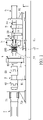
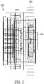
- a reducer angular transmission accuracy tester including a carrier 1, an input bearing seat 2, an output bearing seat 3, an input end encoder 4, an output end encoder 5, a first motor 6, a second motor 7, and a first torsionmeter 8 is provided in the present disclosure.
- the carrier 1 can be used to carry a to-be-tested reducer 100, a type of the to-be-tested reducer 100 is not limited, and the to-be-tested reducer 100 has an input end and an output end.
- the to-be-tested reducer 100 is a harmonic reducer including a wave generator 101, a circular spline ring 102, and a spline cup 103, the wave generator 101 and the spline cup 103 serve as the input end and the output end, respectively.
- the carrier 1 (i.e., jig), is disposed between the input bearing seat 2 and the output bearing seat 3.
- the carrier 1 can be used to carry the to-be-tested reducer 100 and have the to-be-tested reducer 100 disposed between the input bearing seat 2 and the output bearing seat 3, and the input end and the output end of the to-be-tested reducer 100 are connected to the carrier 1, such that the to-be-tested reducer 100 is stably disposed in the carrier 1.
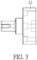
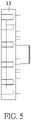
- the carrier 1 can include an input adapter shaft 11, an affixing adapter seat 12, and an output adapter board 13.
- the affixing adapter seat 12 is fixedly disposed on the input bearing seat 2, and the circular spline ring 102 of the to-be-tested reducer 100 can be fixed to the affixing adapter seat 12.
- the input adapter shaft 11 can be rotationally disposed on the affixing adapter seat 12, and the input shaft 30 and the wave generator 101 (i.e., the input end) of the to-be-tested reducer 100 are connected to each other via the input adapter shaft 11.
- the input adapter shaft 11 is pivotally disposed in the affixing adapter seat 12, such that two ends of the input adapter shaft 11 are respectively connected to an end of the input shaft 30 and the wave generator 101.
- the first motor 6 can drive the wave generator 101 through the input shaft 30 and the input adapter shaft 11, such that the to-be-tested reducer 100 can be tested.
- the spline cup 103 i.e., the output end of the to-be-tested reducer 100 and the output shaft 60 can be connected to each other via the output adapter board 13.
- the input encoder 4 and the output end encoder 5 are disposed on the input bearing seat 2 and the output bearing seat 3, respectively, the input end encoder 4 is disposed on a side of the input bearing seat 2 away from the carrier 1, and the output end encoder 5 is disposed on a side of the output bearing seat 3 near the carrier 1.
- the input end encoder 4 and the output end encoder 5 are angular encoders, which can simultaneously capture angular signals of the input end and the output end.
- the output adapter board 13 is disposed between the to-be-tested reducer 100 and the output end encoder 5, such that signals of the output end of the to-be-tested reducer 100 can be transmitted to the output end encoder 5.
- the first motor 6 is disposed on one side of the input bearing seat 2 away from the carrier 1, the input bearing seat 2 and the input end encoder 4 are disposed between the carrier 1 and the first motor 6, and the first motor 6 can be disposed on a motor seat 61.
- the first motor 6 is connected to the carrier 1 and the to-be-tested reducer 100 via the input shaft 30. That is, the first motor 6 can be connected to the input adapter shaft 11 of the carrier 1 through a first shaft connector 10, a second shaft connector 20, and the input shaft 30, such that the first motor 6 is connected to the wave generator 101 of the to-be-tested reducer 100 via the input adapter shaft 11.
- the input shaft 30 is pivotally disposed on the input bearing seat 2, and the input shaft 30 corresponds to the input end encoder 4, such that the input end encoder 4 captures the angular signals of the input end.
- the second motor 7 is disposed on one side of the output bearing seat 3 away from the carrier 1, and the output bearing seat 3 and the output end encoder 5 are disposed between the carrier 1 and the second motor 7.
- the second motor 7 can also be connected to a gear reducer 71, so as to output reducing momentum through the gear reducer 7.
- the second motor 7 and the gear reducer 71 can be disposed on a gear reducer mount 72.
- the second motor 7 is connected to the carrier 1 and the to-be-tested reducer 100 via the output shaft 60.
- the gear reducer 71 of the second motor 7 can be connected to the output adapter board 13 of the carrier 1 through a third shaft connector 40, a fourth shaft connector 50, and the output shaft 60, such that the second motor 7 is connected to the spline cup 103 of the to-be-tested reducer 100 via the output adapter board 13.
- the output shaft 60 is pivotally disposed on the output bearing seat 3, and the output shaft 60 corresponds to the output end encoder 5, such that the output end encoder 5 captures the angular signals of the output end.
- the input shaft 30 and the output shaft 60 are coaxial with each other.
- the first torsionmeter 8 is a torsion sensor, and the first torsionmeter 8 is connected to the second motor 7.
- the first torsionmeter 8 can be disposed between the output end encoder 5 and the second motor 7, and be fixed on a first mount 81.
- the second motor 7 can be connected to the to-be-tested reducer 100 through the first torsionmeter 8 and the output adapter board 13, and when the second motor 7 starts up, the second motor 7 can drive the to-be-tested reducer 100 via the output adapter board 13.
- the first motor 6 can be connected to the wave generator 101 of the to-be-tested reducer 100 through the input shaft 30, the input adapter shaft 11, etc. Therefore, when the first motor 6 starts up, the wave generator 101 can be driven by the input adapter shaft 11, and the input end encoder 4 can capture the angular signals of the input end.
- power can be output by the spline cup 103 of the to-be-tested reducer 100, and the output shaft 60 can be driven by the output adapter board 13, and the output end encoder 5 can capture the angular signals of the output end.
- the reducer angular transmission accuracy tester of the present disclosure can further include a second torsionmeter 9 connected to the first motor 6, the second torsionmeter 9 is a torsion sensor, and the second torsionmeter 9 is disposed between the input end encoder 4 and the first motor 6.
- the second torsionmeter 9 can be fixed on a second mount 91, and the second torsionmeter 9 can be adopted for other test requirements.
- the first motor 6 provided in the present disclosure can drive the input end (i.e., the wave generator 101) of the to-be-tested reducer 100 through the input shaft 30 and the input adapter shaft 11, and drive the output shaft 60 through the output end (i.e., the spline cup 103) of the to-be-tested reducer 100.
- the input end encoder 4 and the output end encoder 5 can capture the signals of the input end and the output end, respectively, and then output results by software programs, so as to perform a test measuring the angular transmission accuracy.
- the second motor 7 provided in the present disclosure can drive the output end (i.e., the spline cup 103) of the to-be-tested reducer 100, the input end (i.e., the wave generator 101) can be fixed to the second motor 7, and the second motor 7 can apply a turning moment to the output end.
- the first torsionmeter 8 can then capture a torsion signal, and the results can be output by the software program for a rigidity test.
- the reducer angular transmission accuracy tester provided in the present disclosure can also be used for tests, e.g. efficiency tests, turning moment tests, etc.
- the reducer angular transmission accuracy tester includes a carrier, an input bearing seat, an output bearing seat, an input end encoder, an output end encoder, a first motor, a second motor, and a first torsionmeter.
- the first motor can drive the input end of the to-be-tested reducer through the input shaft, and drive the output shaft through the output end of the to-be-tested reducer.
- the input end encoder and the output end encoder capture the signals of the input end and the output end, respectively, so as to measure the angular transmission accuracy.
- the second motor can drive the output end of the to-be-tested reducer and apply the turning moment to the output end.
- the first torsionmeter then captures the torsion signal for a rigidity test.
- the reducer angular transmission accuracy tester of the present disclosure can perform various tests on angular transmission accuracy, efficiency, rigidity, and turning moment. Therefore, the reducer angular transmission accuracy tester has preferable applicability, enhanced usage convenience, and a reduced cost in purchasing testers.
- the carrier can be used to carry the to-be-tested reducer, such that the to-be-tested reducer is disposed in the carrier, and the input end and the output end of the to-be-tested reducer are connected to the carrier, thereby stabilizing the to-be-tested reducer and improving the accuracy of the tests.
Landscapes
- Physics & Mathematics (AREA)
- General Physics & Mathematics (AREA)
- Testing Of Devices, Machine Parts, Or Other Structures Thereof (AREA)
Applications Claiming Priority (1)
| Application Number | Priority Date | Filing Date | Title |
|---|---|---|---|
| TW109213302U TWM607568U (zh) | 2020-10-12 | 2020-10-12 | 減速機角度傳遞精度模組試驗機 |
Publications (1)
| Publication Number | Publication Date |
|---|---|
| EP3982103A1 true EP3982103A1 (de) | 2022-04-13 |
Family
ID=74586877
Family Applications (1)
| Application Number | Title | Priority Date | Filing Date |
|---|---|---|---|
| EP21156251.7A Withdrawn EP3982103A1 (de) | 2020-10-12 | 2021-02-10 | Prüfvorrichtung für die winkelübertragungsgenauigkeit eines reduzierers |
Country Status (3)
| Country | Link |
|---|---|
| EP (1) | EP3982103A1 (de) |
| CN (1) | CN213180676U (de) |
| TW (1) | TWM607568U (de) |
Families Citing this family (1)
| Publication number | Priority date | Publication date | Assignee | Title |
|---|---|---|---|---|
| CN113984382B (zh) * | 2021-12-27 | 2022-03-25 | 四川诚邦浩然测控技术有限公司 | 一种角度传感器安装工装 |
Citations (5)
| Publication number | Priority date | Publication date | Assignee | Title |
|---|---|---|---|---|
| CN108871766A (zh) * | 2018-07-11 | 2018-11-23 | 广东南大机器人有限公司 | 一种谐波减速器扭转刚度测试平台 |
| CN109342061A (zh) * | 2018-09-03 | 2019-02-15 | 上海大学 | 内力耗散力矩平衡式谐波传动双柔性构件性能试验装置 |
| CN109470471A (zh) * | 2018-11-26 | 2019-03-15 | 郑州高端装备与信息产业技术研究院有限公司 | 一种减速器综合性能试验台和减速器性能双向测试试验台 |
| CN209624050U (zh) * | 2019-03-08 | 2019-11-12 | 广东省东莞市质量监督检测中心 | 一种机器人谐波减速器重复定位精度测量试验台 |
| CN111189634A (zh) * | 2020-03-18 | 2020-05-22 | 中国船舶重工集团公司第七0七研究所 | 一种大型rv减速器传动误差测试装置及测试方法 |
-
2020
- 2020-10-12 TW TW109213302U patent/TWM607568U/zh not_active IP Right Cessation
- 2020-10-23 CN CN202022393000.6U patent/CN213180676U/zh not_active Expired - Fee Related
-
2021
- 2021-02-10 EP EP21156251.7A patent/EP3982103A1/de not_active Withdrawn
Patent Citations (5)
| Publication number | Priority date | Publication date | Assignee | Title |
|---|---|---|---|---|
| CN108871766A (zh) * | 2018-07-11 | 2018-11-23 | 广东南大机器人有限公司 | 一种谐波减速器扭转刚度测试平台 |
| CN109342061A (zh) * | 2018-09-03 | 2019-02-15 | 上海大学 | 内力耗散力矩平衡式谐波传动双柔性构件性能试验装置 |
| CN109470471A (zh) * | 2018-11-26 | 2019-03-15 | 郑州高端装备与信息产业技术研究院有限公司 | 一种减速器综合性能试验台和减速器性能双向测试试验台 |
| CN209624050U (zh) * | 2019-03-08 | 2019-11-12 | 广东省东莞市质量监督检测中心 | 一种机器人谐波减速器重复定位精度测量试验台 |
| CN111189634A (zh) * | 2020-03-18 | 2020-05-22 | 中国船舶重工集团公司第七0七研究所 | 一种大型rv减速器传动误差测试装置及测试方法 |
Non-Patent Citations (1)
| Title |
|---|
| KALENDER T ET AL: "NEUE VERFAHREN IN DER QUALITATS-KONTROLLE VON PRAZISIONSGETRIEBEN", ANTRIEBSTECHNIK, VEREINIGTE FACHVERLAGE, MAINZ, DE, vol. 32, no. 9, 1 September 1993 (1993-09-01), XP000395411, ISSN: 0722-8546 * |
Also Published As
| Publication number | Publication date |
|---|---|
| TWM607568U (zh) | 2021-02-11 |
| CN213180676U (zh) | 2021-05-11 |
Similar Documents
| Publication | Publication Date | Title |
|---|---|---|
| CN207408034U (zh) | 一种扭矩扳子的检测设备 | |
| US6408685B2 (en) | Method and system for measuring interference between valve and piston of an internal combustion engine | |
| CN103728132A (zh) | 减速机传动效率/故障检测系统及方法 | |
| CN108896259A (zh) | 一种船舶推进轴系-螺旋桨耦合振动实验台 | |
| CN202372329U (zh) | 一种船舶轴系振动实验装置 | |
| CN101644624A (zh) | 电封闭式履带车辆传动装置转向试验台 | |
| CN106768942A (zh) | 用于标定旋转型柔性元件刚度、阻尼特性的实验测试平台 | |
| CN109471029A (zh) | 一种有限转角力矩电机性能测试装置及测试方法 | |
| CN106324500B (zh) | 电机耐久性测试设备 | |
| CN109000777A (zh) | 一种船舶轴系扭转振动测量系统校准装置 | |
| CN204269364U (zh) | 齿轮传动测量装置及具有其的航空发动机齿轮传动系统 | |
| KR20240045843A (ko) | 하모닉 감속기 시험장치 | |
| US11385257B2 (en) | Apparatus for testing electronic components | |
| CN103900747A (zh) | 偏心误差修正式的船舶轴系扭矩测量探头 | |
| CN109141877A (zh) | 一种用于驱动电机的轴承试验装置 | |
| CN213180676U (zh) | 减速机角度传递精度模块试验机 | |
| CN201837449U (zh) | 一种新型曲轴扭转减振器扭振试验装置 | |
| KR102573766B1 (ko) | 회전력전달축의 성능 시험 장치 및 성능 시험 방법 | |
| CN115683607A (zh) | 一种精密直角减速机扭转刚度与回差检测装置 | |
| CN116176857A (zh) | 一种适用于航空自导深弹舵机的测试装置及方法 | |
| CN208282807U (zh) | 一种vvt锁销间隙检测装置 | |
| CN204740135U (zh) | 一种船舶轴系扭转振动测试装置 | |
| US5971275A (en) | System for verifying nuclear warhead prearm/safing signals | |
| CN209803164U (zh) | 一种拖拉机用编码器快速测速装置 | |
| CN202332064U (zh) | 电动机转子动平衡实训装置 |
Legal Events
| Date | Code | Title | Description |
|---|---|---|---|
| PUAI | Public reference made under article 153(3) epc to a published international application that has entered the european phase |
Free format text: ORIGINAL CODE: 0009012 |
|
| STAA | Information on the status of an ep patent application or granted ep patent |
Free format text: STATUS: THE APPLICATION HAS BEEN PUBLISHED |
|
| AK | Designated contracting states |
Kind code of ref document: A1 Designated state(s): AL AT BE BG CH CY CZ DE DK EE ES FI FR GB GR HR HU IE IS IT LI LT LU LV MC MK MT NL NO PL PT RO RS SE SI SK SM TR |
|
| STAA | Information on the status of an ep patent application or granted ep patent |
Free format text: STATUS: THE APPLICATION IS DEEMED TO BE WITHDRAWN |
|
| 18D | Application deemed to be withdrawn |
Effective date: 20221014 |