EP3982109B1 - Dispositif de détermination de détérioration de liquide et unité hydraulique - Google Patents
Dispositif de détermination de détérioration de liquide et unité hydraulique Download PDFInfo
- Publication number
- EP3982109B1 EP3982109B1 EP20847584.8A EP20847584A EP3982109B1 EP 3982109 B1 EP3982109 B1 EP 3982109B1 EP 20847584 A EP20847584 A EP 20847584A EP 3982109 B1 EP3982109 B1 EP 3982109B1
- Authority
- EP
- European Patent Office
- Prior art keywords
- detection value
- hydraulic oil
- ratio
- deterioration
- liquid
- Prior art date
- Legal status (The legal status is an assumption and is not a legal conclusion. Google has not performed a legal analysis and makes no representation as to the accuracy of the status listed.)
- Active
Links
Images




Classifications
-
- G—PHYSICS
- G01—MEASURING; TESTING
- G01N—INVESTIGATING OR ANALYSING MATERIALS BY DETERMINING THEIR CHEMICAL OR PHYSICAL PROPERTIES
- G01N21/00—Investigating or analysing materials by the use of optical means, i.e. using sub-millimetre waves, infrared, visible or ultraviolet light
- G01N21/17—Systems in which incident light is modified in accordance with the properties of the material investigated
- G01N21/25—Colour; Spectral properties, i.e. comparison of effect of material on the light at two or more different wavelengths or wavelength bands
-
- G—PHYSICS
- G01—MEASURING; TESTING
- G01N—INVESTIGATING OR ANALYSING MATERIALS BY DETERMINING THEIR CHEMICAL OR PHYSICAL PROPERTIES
- G01N21/00—Investigating or analysing materials by the use of optical means, i.e. using sub-millimetre waves, infrared, visible or ultraviolet light
- G01N21/17—Systems in which incident light is modified in accordance with the properties of the material investigated
- G01N21/25—Colour; Spectral properties, i.e. comparison of effect of material on the light at two or more different wavelengths or wavelength bands
- G01N21/31—Investigating relative effect of material at wavelengths characteristic of specific elements or molecules, e.g. atomic absorption spectrometry
-
- F—MECHANICAL ENGINEERING; LIGHTING; HEATING; WEAPONS; BLASTING
- F16—ENGINEERING ELEMENTS AND UNITS; GENERAL MEASURES FOR PRODUCING AND MAINTAINING EFFECTIVE FUNCTIONING OF MACHINES OR INSTALLATIONS; THERMAL INSULATION IN GENERAL
- F16N—LUBRICATING
- F16N29/00—Special means in lubricating arrangements or systems providing for the indication or detection of undesired conditions; Use of devices responsive to conditions in lubricating arrangements or systems
-
- G—PHYSICS
- G01—MEASURING; TESTING
- G01N—INVESTIGATING OR ANALYSING MATERIALS BY DETERMINING THEIR CHEMICAL OR PHYSICAL PROPERTIES
- G01N21/00—Investigating or analysing materials by the use of optical means, i.e. using sub-millimetre waves, infrared, visible or ultraviolet light
- G01N21/01—Arrangements or apparatus for facilitating the optical investigation
-
- G—PHYSICS
- G01—MEASURING; TESTING
- G01N—INVESTIGATING OR ANALYSING MATERIALS BY DETERMINING THEIR CHEMICAL OR PHYSICAL PROPERTIES
- G01N33/00—Investigating or analysing materials by specific methods not covered by groups G01N1/00 - G01N31/00
- G01N33/26—Oils; Viscous liquids; Paints; Inks
- G01N33/28—Oils, i.e. hydrocarbon liquids
- G01N33/2888—Lubricating oil characteristics, e.g. deterioration
-
- F—MECHANICAL ENGINEERING; LIGHTING; HEATING; WEAPONS; BLASTING
- F16—ENGINEERING ELEMENTS AND UNITS; GENERAL MEASURES FOR PRODUCING AND MAINTAINING EFFECTIVE FUNCTIONING OF MACHINES OR INSTALLATIONS; THERMAL INSULATION IN GENERAL
- F16N—LUBRICATING
- F16N2250/00—Measuring
- F16N2250/34—Transparency; Light; Photo sensor
-
- G—PHYSICS
- G01—MEASURING; TESTING
- G01N—INVESTIGATING OR ANALYSING MATERIALS BY DETERMINING THEIR CHEMICAL OR PHYSICAL PROPERTIES
- G01N21/00—Investigating or analysing materials by the use of optical means, i.e. using sub-millimetre waves, infrared, visible or ultraviolet light
- G01N21/17—Systems in which incident light is modified in accordance with the properties of the material investigated
- G01N21/25—Colour; Spectral properties, i.e. comparison of effect of material on the light at two or more different wavelengths or wavelength bands
- G01N21/251—Colorimeters; Construction thereof
Definitions
- the present invention relates to liquid deterioration determination devices and hydraulic units.
- a conventional liquid deterioration determination device includes a light emitting element that emits detection light to lubricant, and a light receiving element that acquires a detection value representing color information of the detection light transmitted through the lubricant (see Patent Literature 1).
- This liquid deterioration determination device includes a determination unit that calculates brightness or a color component maximum difference from the detection value and determines deterioration of lubricant from a temporal change of the brightness or the color component maximum difference.
- Patent Literature 2 discloses a liquid deterioration determination device comprising a light receiver configured to receive detection light transmitted through a liquid or detection light reflected by the liquid, a determination unit configured to determine the degree of deterioration of the liquid, the light receiver being configured to output a first detection value representing an amount of a light component of a first color included in the detection light transmitted through the liquid or the detection light reflected by the liquid and a second detection value representing an amount of a light component of a second color different from the first color and included in the detection light transmitted through the liquid or the detection light reflected by the liquid, and the determination unit being configured to determine the degree of deterioration of the liquid based on a ratio of the second detection value to the first detection value.
- Patent Literature 5 discloses a hand-carried spectrometric portable oil tester.
- the present invention proposes a liquid deterioration determination device that can determine deterioration of a liquid with a simple configuration.
- the present invention provides a device for determining liquid deterioration in a tank according to claim 1.
- the degree of deterioration of the liquid can be determined with a simple configuration without continuously detecting the detection value representing the amount of the detection light transmitted through the liquid or the detection light reflected by the liquid.
- the liquid deterioration determination device comprises a light emitter configured to emit the light into the liquid and provided integrally within the casing.
- the light receiver is configured to output a third detection value representing an amount of a light component of a third color different from the first color and the second color and included in the light transmitted through the liquid or the light reflected by the liquid.
- each of the first color, the second color, and the third color is any one of red, green, and blue.
- the first color is red.
- Another aspect of the present invention provides a hydraulic unit having the above-described liquid deterioration determination device.
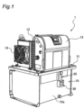
- Fig. 1 is a perspective view of a hydraulic unit 1 according to a first embodiment of the present disclosure.
- the hydraulic unit 1 according to the present embodiment supplies hydraulic oil to an external apparatus such as a machining tool.
- the hydraulic unit 1 includes a hydraulic oil tank 10 that accommodates hydraulic oil, and a mount 11 attached to an upper part of the hydraulic oil tank 10.
- the hydraulic unit 1 includes a hydraulic pump (not shown), a motor (not shown) that drives the hydraulic pump, an oil cooler 12 that cools hydraulic oil discharged from the hydraulic pump, and a controller 13 that controls the motor.
- the hydraulic pump, the motor, the oil cooler 12, and the controller 13 are mounted on the mount 11, and the hydraulic oil tank 10 is disposed below the mount 11.
- the hydraulic unit 1 includes a cooling fan 14 that supplies cooling air to the motor and the oil cooler 12.
- the hydraulic unit 1 is herein described by way of example only; and not limited to the above-described structure.
- a liquid level gauge 20 for externally checking the amount of hydraulic oil accommodated in the hydraulic oil tank 10 is attached to a metal side surface 10a of the hydraulic oil tank 10. Since the liquid level gauge 20 is attached to the side surface 10a of the hydraulic oil tank 10, a user can easily visually check the amount of hydraulic oil accommodated in the hydraulic oil tank 10.
- a liquid sensor 30 that determines the degree of deterioration of liquid is attached to an outside of the liquid level gauge 20.
- the liquid sensor 30 according to the present embodiment is an example of a liquid deterioration determination device according to the present invention.
- Fig. 2 is a schematic front view showing the liquid level gauge 20 and the liquid sensor 30 according to the present embodiment.
- Fig. 3 is a schematic cross-sectional view taken along a line III-III in Fig. 2 .
- illustration of a detailed structure of the inside of the liquid sensor 30 is omitted.
- the same constituent elements as in Fig. 1 are denoted by the same reference signs as in Fig. 1 .
- the liquid level gauge 20 of the present embodiment is an oil level gauge for checking the oil level of the hydraulic oil accommodated in the hydraulic oil tank 10.
- the liquid level gauge 20 of the present embodiment includes a liquid level gauge main body 21 made of a transparent acrylic resin and two bolts 22A and 22B for fixing the liquid level gauge main body 21 to the hydraulic oil tank 10.
- the liquid level gauge 20 according to the present embodiment is an example of a translucent tubular member into which the liquid (hydraulic oil in the present embodiment) according to the present invention is introduced.
- the liquid level gauge main body 21 of the present embodiment has a substantially rectangular parallelepiped shape, and is attached to the hydraulic oil tank 10 such that the liquid level gauge main body 21 has a longitudinal direction that extends along the vertical direction.
- the liquid level gauge main body 21 is hollow.
- the liquid level gauge main body 21 includes a hollow portion 21a being a space extending in the longitudinal direction inside the liquid level gauge main body 21.
- the hydraulic oil is introduced into the hollow portion 21a of the liquid level gauge main body 21 according to the amount of hydraulic oil stored in the hydraulic oil tank 10. The user can check the amount of hydraulic oil accommodated in the hydraulic oil tank 10 by visually observing the oil level of the hydraulic oil in the hollow portion 21a of the liquid level gauge main body 21.
- the liquid level gauge main body 21 is provided with an upper limit line HL indicating the upper limit of an allowable range of the oil level of the hydraulic oil and a lower limit line LL indicating the lower limit of the allowable range of the oil level of the hydraulic oil.
- each of the bolts 22A and 22B of the present embodiment are made of metal. As shown in Fig. 3 , each of the bolts 22A and 22B includes a communication portion22c extending in the axial direction from a tip portion 22a toward a head portion 22b of the bolt. The communication portion 22c is open in the radial direction at an axial end portions on the head portion 22b side of each of the bolts 22A and 22B. In other words, the bolts 22A and 22B are what are called perforated bolts.
- the communication portion 22c of the bolt 22B opens at the tip portion 22a into an area where the hydraulic oil accumulated in the hydraulic oil tank 10 exits. At this time, the hydraulic oil is introduced from the hydraulic oil tank 10 into the hollow portion 21a of the liquid level gauge main body 21 through the communication portion 22c of the bolt 22B. In addition, the communication portion 22c of the bolt 22B is filled with the hydraulic oil.
- the oil level of the hydraulic oil introduced into the liquid level gauge main body 21 coincides with the oil level of the hydraulic oil accommodated in the hydraulic oil tank 10.
- the user can check the amount of hydraulic oil accommodated in the hydraulic oil tank 10 by visually observing the oil level of the hydraulic oil introduced into the hollow portion 21a of the liquid level gauge main body 21.
- the liquid sensor 30 of the present embodiment is a sensor for detecting the degree of deterioration of the hydraulic oil accommodated in the hydraulic oil tank 10. More specifically, the liquid sensor 30 is a transmissive color sensor. As shown in Fig. 2 , the liquid sensor 30 of the present embodiment includes a U-shaped casing 31, a light emitter 32 that emits detection light, and a light receiver 33 that receives the detection light emitted from the light emitter 32.
- the light emitter 32 and the light receiver 33 are provided integrally with the casing 31 so as to face each other.
- the light emitter 32 and the light receiver 33 are provided integrally with the casing 31 in a manner that the optical axis of the light emitter 32 and the optical axis of the light receiver 33 coincide with each other.
- the liquid sensor 30 is attached to the liquid level gauge main body 21 such that the light emitter 32 and the light receiver 33 face each other across the liquid level gauge main body 21.
- the liquid sensor 30 is attached to the liquid level gauge 20 such that height positions of the light emitter 32 and the light receiver 33 overlap with a height position of the lower limit line LL of the liquid level gauge main body 21.
- a packing (not shown) is provided between the casing 31 of the liquid sensor 30 and the liquid level gauge main body 21 of the present embodiment. This packing makes the casing 31 and the liquid level gauge main body 21 water-resistant and dust-resistant, prevents external light from entering the liquid level gauge main body 21, and brings the casing into close contact with the liquid gauge main body 21 so that the casing 31 is held by the liquid level gauge main body 21.
- the light emitter 32 of the present embodiment includes a light emitting element for emitting light and a drive circuit for driving the light emitting element.
- the light emitting element of the present embodiment is a white light emitting diode. In other words, the light emitter 32 of the present embodiment emits white light.
- the light receiver 33 of the present embodiment includes a light receiving element that converts the amount of light into an electric signal, an amplifier circuit that amplifies the electric signal output from the light receiving element, and an A/D conversion circuit that converts the analog electric signal amplified by the amplifier circuit into a digital electric signal.
- the light receiving element of the present embodiment is an RGB color sensor, and can detect the electric signal converted from received visible light separately for each of red, green, and blue.
- the red in the present embodiment is an example of a first color according to the present invention.
- the blue in the present embodiment is an example of a second color according to the present invention.
- the green in the present embodiment is an example of a third color according to the present invention.
- the detection value indicating the amount of light is output as, for example, an output voltage or an output current from the light receiver 33.
- the red detection value R of the present embodiment is output as an output voltage or an output current from the light receiver 33 for the red included in the detection light transmitted through the hydraulic oil in the liquid level gauge 20.
- the green detection value G of the present embodiment is output as an output voltage or an output current from the light receiver 33 for the blue included in the detection light transmitted through the hydraulic oil in the liquid level gauge 20.
- the blue detection value B of the present embodiment is output as an output voltage or an output current from the light receiver 33 for the green included in the detection light transmitted through the hydraulic oil in the liquid level gauge 20.
- the liquid sensor 30 of the present embodiment further includes a thermoelectric conversion element 34 that converts heat into electric power.
- the thermoelectric conversion element 34 of the present embodiment is provided so as to be in contact with the side surface 10a of the hydraulic oil tank 10.
- the side surface 10a of the hydraulic oil tank 10 is likely to have a high temperature because the hydraulic oil accommodated in the hydraulic oil tank 10 has a high temperature due to heat generation from a sliding portion of the machining tool or the like.
- the thermoelectric conversion element 34 generates power using a temperature difference between the temperature of the side surface 10a of the hydraulic oil tank 10 and the temperature of the air around the liquid sensor 30.
- Fig. 4 is a schematic cross-sectional view taken along a line IV-IV in Fig. 3 .
- illustration of a detailed structure of the inside of the liquid sensor 30 is omitted.
- the same components as in Figs. 1 to 3 are denoted by the same reference signs as in Figs. 1 to 3 .
- the hollow portion 21a of the liquid level gauge main body 21 has a circular cross-sectional shape in the cross section shown in Fig. 4 .
- the liquid sensor 30 of the present embodiment includes a wireless transmitter 35 that wirelessly transmits a signal to the external apparatus, a wireless receiver 36 that wirelessly receives a signal from the external apparatus, and a control device 37.
- the amount of change in the green detection value G accompanying the change in the ASTM color is larger than the amount of change in the red detection value R accompanying the change in the ASTM color, and is smaller than the amount of change in the blue detection value B accompanying the change in the ASTM color.
- the amount of change in the blue detection value B accompanying the change in the ASTM color is larger than the amounts of change in the red detection value R and the green detection value G accompanying the change in the ASTM color.
- Fig. 7 is a diagram showing a relationship between the ratios of the red detection value R, the green detection value G, and the blue detection value B to the red detection value R and the ASTM color of the hydraulic oil.
- the vertical axis in Fig. 7 indicates the ratio of each detection value to the red detection value R.
- the horizontal axis in Fig. 7 indicates the ASTM color indicating the hue of the hydraulic oil.
- a ratio R/R of the red detection value R to the red detection value R is indicated by a square mark.
- the ratio G/R of the green detection value G to the red detection value R is indicated by a circle mark.
- the ratio B/R of the blue detection value B to the red detection value R is indicated by a triangle mark.
- the determination unit 37a of the present embodiment calculates the ratio G/R of the green detection value G to the red detection value R from the red detection value R and the green detection value G output from the light receiver 33.
- the determination unit 37a determines the degree of deterioration of the hydraulic oil from the ratio G/R calculated from the detection value.
- the determination unit 37a determines that the hydraulic oil is deteriorated when the calculated ratio G/R of the green detection value G to the red detection value R is smaller than a predetermined threshold ⁇ 1 (for example, the ratio G/R corresponding to the value of ASTM color of 4.0, see a two-dot chain line in the drawing).
- a predetermined threshold ⁇ 1 for example, the ratio G/R corresponding to the value of ASTM color of 4.0, see a two-dot chain line in the drawing.
- the determination unit 37a of the present embodiment determines that the hydraulic oil is deteriorated when the calculated ratio B/R of the blue detection value B to the red detection value R is smaller than the predetermined threshold ⁇ 1, or when the calculated ratio G/R of the green detection value G to the red detection value R is smaller than the predetermined threshold ⁇ 1.
- the degree of deterioration of the hydraulic oil may not be uniquely determined for one color difference R-B, and there is a risk that the determination unit 37a erroneously detects the degree of deterioration of the hydraulic oil.
- the determination unit 37a determines that the hydraulic oil is not deteriorated because the color difference R-B is smaller than the threshold ⁇ even when the value of the ASTM color is larger than 7.0.
- the determination unit 37a determines that the hydraulic oil is deteriorated when the calculated ratio B/R of the blue detection value B to the red detection value R is smaller than the predetermined threshold ⁇ 1 or when the calculated ratio G/R of the green detection value G to the red detection value R is smaller than the predetermined threshold ⁇ 1, but the present invention is not limited thereto.
- the determination unit 37a may determine that the hydraulic oil is deteriorated when the calculated ratio B/R of the blue detection value B to the red detection value R is smaller than the predetermined threshold ⁇ 1 and also when the calculated ratio G/R of the green detection value G to the red detection value R is smaller than the predetermined threshold ⁇ 1.
- the determination unit 37a determines the degree of deterioration of the hydraulic oil based on the ratio B/R of the blue detection value B to the red detection value R and also on the ratio G/R of the green detection value G to the red detection value R, but the present invention is not limited thereto.
- the determination unit 37a may determine the degree of deterioration of the hydraulic oil only by the ratio B/R of the blue detection value B to the red detection value R, or may determine the degree of deterioration of the hydraulic oil only by the ratio G/R of the green detection value G to the red detection value R.
- the determination unit 37a determines the degree of deterioration of the hydraulic oil based on the ratio G/R of the green detection value G to the red detection value R, but the present invention is not limited thereto.
- the determination unit 37a may use a ratio (G + c)/R or a ratio G/(R + c) to determine the degree of deterioration of the hydraulic oil.
- c is any number, and may be a constant or a variable. That is, the determination unit 37a may determine the degree of deterioration of the hydraulic oil based on a ratio that includes the ratio G/R.
- the ratio G/R of the green detection value G to the red detection value R used by the determination unit 37a to determine the degree of deterioration of the hydraulic oil is not strictly limited to itself, but may include at least the ratio G/R, and may be appropriately modified within this range.
- a hydraulic unit 1 of a second embodiment has the same configuration as the hydraulic unit 1 of the first embodiment except for the first color, the second color, and the third color, and the first detection value, the second detection value, and the third detection value, and the description of the first embodiment referring to Figs. 1 to 6 is applied to the second embodiment.
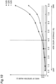
- Fig. 9 is a diagram showing a relationship between the ratios of the red detection value R, the green detection value G, and the blue detection value B to the green detection value G and the ASTM color of the hydraulic oil.
- the vertical axis in Fig. 9 indicates the ratio of each detection value to the green detection value G.
- the horizontal axis in Fig. 9 indicates the ASTM color indicating the hue of the hydraulic oil.
- the ratio R/G of the red detection value R to the green detection value G is indicated by a square mark.
- a ratio G/G of the green detection value G to the green detection value G is indicated by a circle mark.
- the ratio B/G of the blue detection value B to the green detection value G is indicated by a triangle mark.
- the ratio R/G of the red detection value R to the green detection value G increases generally monotonically as the value of the ASTM color increases. In other words, the ratio R/G of the red detection value R to the green detection value G increases generally monotonically as the degree of deterioration of the hydraulic oil progresses.
- the ratio B/G of the blue detection value B to the green detection value G decreases monotonically as the value of the ASTM color increases. In other words, the ratio B/G of the blue detection value B to the green detection value G decreases monotonically as the degree of deterioration of the hydraulic oil progresses.
- the amount of change in the ratio B/G of the blue detection value B to the green detection value G accompanying the change in the ASTM color is larger than the amount of change in the ratio R/G of the red detection value R to the green detection value G accompanying the change in the ASTM color.
- the determination unit 37a determines the degree of deterioration of the hydraulic oil based on the correspondence relationship shown in Fig. 9 between the degree of deterioration of the hydraulic oil and the ratio B/G of the blue detection value B to the green detection unit G. Specifically, first, the determination unit 37a of the present embodiment calculates the ratio B/G of the blue detection value B to the green detection value G from the green detection value G and the blue detection value B output from a light receiver 33. Next, based on the correspondence relationship between the degree of deterioration of the hydraulic oil and the ratio B/G, the determination unit 37a determines the degree of deterioration of the hydraulic oil from the ratio B/G calculated from the detection values.
- the determination unit 37a of the present embodiment determines the degree of deterioration of the hydraulic oil based on the ratio R/G of the red detection value R to the green detection value G.
- the determination unit 37a determines the degree of deterioration of the hydraulic oil based on the correspondence relationship shown in Fig. 9 between the degree of deterioration of the hydraulic oil and the ratio R/G of the red detection value R to the green detection value G. Specifically, first, the determination unit 37a of the present embodiment calculates the ratio R/G of the red detection value R to the green detection value G from the green detection value G and the red detection value R output from the light receiver 33. Next, based on the correspondence relationship between the degree of deterioration of the hydraulic oil and the ratio R/G, the determination unit 37a determines the degree of deterioration of the hydraulic oil from the calculated ratio R/G.
- the control device 37 controls the light emitter 32 to emit light to notify the user of the deterioration.
- the determination unit 37a determines that the hydraulic oil is deteriorated when the calculated ratio B/G of the blue detection value B to the green detection value G is smaller than a predetermined threshold ⁇ 2 (for example, the ratio B/G corresponding to the value of ASTM color of 4.0, see a two-dot chain line in the drawing).
- the determination unit 37a determines that the hydraulic oil is deteriorated when the calculated ratio R/G of the red detection value R to the green detection value G is larger than a predetermined threshold ⁇ 2 (for example, the ratio R/G corresponding to the value of ASTM color of 4.0, see a two-dot chain line in the drawing).
- a predetermined threshold ⁇ 2 for example, the ratio R/G corresponding to the value of ASTM color of 4.0, see a two-dot chain line in the drawing.
- the determination unit 37a of the present embodiment determines that the hydraulic oil is deteriorated when the calculated ratio B/G of the blue detection value B to the green detection unit G is smaller than the predetermined threshold ⁇ 2 or when the calculated ratio R/G of the red detection value R to the green detection unit G is larger than the predetermined threshold ⁇ 2.
- the second embodiment exhibits operational effects similar to those of the first embodiment.
- the determination unit 37a determines that the hydraulic oil is deteriorated when the calculated ratio B/G of the blue detection value B to the green detection unit G is smaller than the predetermined threshold ⁇ 2 or when the calculated ratio R/G of the red detection value R to the green detection unit G is larger than the predetermined threshold ⁇ 2, but the present invention is not limited thereto.
- the determination unit 37a may determine that the hydraulic oil is deteriorated when the calculated ratio B/G of the blue detection value B to the green detection unit G is smaller than a predetermined threshold ⁇ 2 and also when the calculated ratio R/G of the red detection value R to the green detection unit G is larger than the predetermined threshold ⁇ 2.
- the determination unit 37a determines the degree of deterioration of the hydraulic oil based on the ratio B/G of the blue detection value B to the green detection value G and also on the ratio R/G of the red detection value R to the green detection value G, but the present invention is not limited thereto.
- the determination unit 37a may determine the degree of deterioration of the hydraulic oil only by the ratio B/G of the blue detection value B to the green detection value G, or may determine the degree of deterioration of the hydraulic oil only by the ratio R/G of the red detection value R to the green detection value G.
- the determination unit 37a determines the degree of deterioration of the hydraulic oil based on the ratio B/G of the blue detection value B to the green detection value G, but, for example, the determination unit 37a may use a ratio (B + c)/G or a ratio B/(G + c) to determine the degree of deterioration of the hydraulic oil.
- c is any number, and may be a constant or a variable. That is, the determination unit 37a may determine the degree of deterioration of the hydraulic oil based on a ratio that includes the ratio B/G.
- the ratio B/G of the blue detection value B to the green detection value G used by the determination unit 37a to determine the degree of deterioration of the hydraulic oil is not strictly limited to itself, but may include at least the ratio B/G, and may be appropriately modified within this range.
- the determination unit 37a determines the degree of deterioration of the hydraulic oil based on the ratio R/G of the red detection value R to the green detection value G, but the present invention is not limited thereto.
- the determination unit 37a may use a ratio (R + c)/G or a ratio R/(G + c) to determine the degree of deterioration of the hydraulic oil.
- c is any number, and may be a constant or a variable. That is, the determination unit 37a may determine the degree of deterioration of the hydraulic oil based on a ratio that includes the ratio R/G.
- the ratio R/G of the red detection value R to the green detection value G used by the determination unit 37a to determine the degree of deterioration of the hydraulic oil is not strictly limited to itself, but may include at least the ratio R/G, and may be appropriately modified within this range.
- a hydraulic unit 1 of a third embodiment has the same configuration as the hydraulic unit 1 of the first embodiment except for the first color, the second color, and the third color, and the first detection value, the second detection value, and the third detection value, and the description or the first embodiment referring to Figs. 1 to 6 is applied to the third embodiment.
- a determination unit 37a of the present embodiment determines the degree of deterioration of the hydraulic oil from a ratio R/B of the red detection value R to the blue detection value B and a ratio G/B of the green detection value G to the blue detection value B.
- the blue in the present embodiment is an example of the first color according to the present invention
- the blue detection value B in the present embodiment is an example of the first detection value according to the present invention.
- the red in the present embodiment is an example of the second color according to the present invention
- the red detection value R in the present embodiment is an example of the second detection value according to the present invention.
- the green of the present embodiment is an example of the third color according to the present invention
- the green detection value G is an example of the third detection value according to the present invention.
- Fig. 10 is a diagram showing a relationship between the ratios of the red detection value R, the green detection value G, and the blue detection value B to the blue detection value B and the ASTM color of the hydraulic oil.
- the vertical axis in Fig. 10 indicates the ratio of each detection value to the blue detection value B.
- the horizontal axis in Fig. 10 indicates the ASTM color indicating the hue of the hydraulic oil.
- the ratio R/B of red detection value R to blue detection value B is indicated by a square mark.
- the ratio G/B of the blue detection value B to the blue detection value B is indicated by a circle mark.
- a ratio B/B of the blue detection value B to the blue detection value B is indicated by a triangle mark.
- the ratio R/B of the red detection value R to the blue detection value B increases generally monotonically as the value of the ASTM color increases. In other words, the ratio R/B of the red detection value R to the blue detection value B increases monotonically as the degree of deterioration of the hydraulic oil progresses. Similarly, the ratio G/B of the green detection value G to the blue detection value B increases monotonically as the value of the ASTM color increases. In other words, the ratio G/B of the green detection value G to the blue detection value B increases monotonically as the degree of deterioration of the hydraulic oil progresses.
- the determination unit 37a determines the degree of deterioration of the hydraulic oil based on the correspondence relationship shown in Fig. 10 between the degree of deterioration of the hydraulic oil and the ratio R/B of the red detection value R to the blue detection value B. Specifically, first, the determination unit 37a of the present embodiment calculates the ratio R/B of the red detection value R to the blue detection value B from the blue detection value B and the red detection value R output from a light receiver 33. Next, based on the correspondence relationship between the degree of deterioration of the hydraulic oil and the ratio R/B, the determination unit 37a determines the degree of deterioration of the hydraulic oil from the calculated ratio R/B.
- the determination unit 37a of the present embodiment determines the degree of deterioration of the hydraulic oil based on the ratio G/B of the green detection value G to the blue detection value B.
- the determination unit 37a determines the degree of deterioration of the hydraulic oil based on the correspondence relationship shown in Fig. 10 between the degree of deterioration of the hydraulic oil and the ratio G/B of the green detection value G to the blue detection value B. Specifically, first, the determination unit 37a of the present embodiment calculates the ratio G/B of the green detection value G to the blue detection value B from the blue detection value B and the green detection value G output from the light receiver 33. Next, based on the correspondence relationship between the degree of deterioration of the hydraulic oil and the ratio G/B, the determination unit 37a determines the degree of deterioration of the hydraulic oil from the calculated ratio G/B.
- the control device 37 controls the light emitter 32 to emit light to notify the user of the deterioration.
- the determination unit 37a determines that the hydraulic oil is deteriorated when the calculated ratio R/B of the red detection value R to the blue detection value B is larger than a predetermined threshold ⁇ 3 (for example, the ratio R/B corresponding to the value of ASTM color of 4.0, see a two-dot chain line in the drawing).
- the third embodiment exhibits operational effects similar to those of the first embodiment.
- the determination unit 37a determines the degree of deterioration of the hydraulic oil based on the ratio R/B of the red detection value R to the blue detection value B and also on the ratio G/B of the green detection value G to the blue detection value B, but the present invention is not limited thereto.
- the determination unit 37a may determine the degree of deterioration of the hydraulic oil only by the ratio R/B of the red detection value R to the blue detection value B, or may determine the degree of deterioration of the hydraulic oil only by the ratio G/B of the green detection value G to the blue detection value B.
- the determination unit 37a determines the degree of deterioration of the hydraulic oil based on the ratio R/B of the red detection value R to the blue detection value B, but the present invention is not limited thereto.
- the determination unit 37a may use a ratio (R + c)/B or a ratio R/(B + c) to determine the degree of deterioration of the hydraulic oil.
- c is any number, and may be a constant or a variable. That is, the determination unit 37a may determine the degree of deterioration of the hydraulic oil based on a ratio that includes the ratio R/B.
- the ratio R/B of the red detection value R to the blue detection value B used by the determination unit 37a to determine the degree of deterioration of the hydraulic oil is not strictly limited to itself, but may include at least the ratio R/B, and may be appropriately modified within this range.
- the determination unit 37a determines the degree of deterioration of the hydraulic oil based on the ratio G/B of the green detection value G to the blue detection value B, but the present invention is not limited thereto.
- the determination unit 37a may use a ratio (G + c)/B or a ratio G/(B + c) to determine the degree of deterioration of the hydraulic oil.
- c is any number, and may be a constant or a variable. That is, the determination unit 37a may determine the degree of deterioration of the hydraulic oil based on a ratio that includes the ratio G/B.
- a liquid sensor 30 of a fourth embodiment has the same configuration as the liquid sensor 30 of the first embodiment except for not including a light emitter 32, and a detailed description thereof is omitted.
- Fig. 11 is a schematic diagram showing a state in which a hydraulic unit 1 according to the present embodiment is installed in a factory.
- the fourth embodiment exhibits operational effects similar to those of the first embodiment.
- the configuration of the liquid sensor 30 can be simplified.
- a liquid sensor 130 of the fifth embodiment has the same configuration as the liquid sensor 30 of the first embodiment except for being a reflective sensor, and detailed description of the same configuration is omitted.
- Fig. 12 is a schematic front view showing a liquid level gauge 20 and the liquid sensor 130 according to the present embodiment.
- the fifth embodiment exhibits operational effects similar to those of the first embodiment.
- the liquid sensor 130 since the light emitter 32 and the light receiver 33 are arranged on the same side with respect to the liquid level gauge main body 21, the liquid sensor 130 can be miniaturized as compared with a case where the light emitter and the light receiver are arranged across the liquid level gauge main body 21.
- liquid sensor 130 is the reflective sensor, it is not necessary to adjust the optical axis of the light emitter 32 and the optical axis of the light receiver 33, and it is possible to easily attach the liquid sensor 130 to the liquid level gauge 20.
- the liquid sensor 30 determines the degree of deterioration of the hydraulic oil of the hydraulic unit 1, but the present invention is not limited thereto, and the degree of deterioration of another liquid such as cutting liquid or coolant may be determined. In addition, the liquid sensor 30 may determine a state in which another liquid is mixed in the hydraulic oil.
- first to fifth embodiments may be appropriately combined and used.
- the first color, the second color, and the third color according to the present disclosure are any one of red, green, and blue, but the colors are not limited thereto, and may be other colors such as yellow or purple. That is, in the first to fifth embodiments, a combination of red, green, and blue is used as the combination of the first to third colors according to the present disclosure, but the combination is not limited thereto, and for example, a combination of magenta, yellow, and cyan may be used.
- the liquid level gauge 20 being an example of the accommodation unit of the present invention includes the liquid level gauge main body 21 having a substantially rectangular parallelepiped shape, but the present invention is not limited thereto.
- the liquid level gauge 20 being an example of the accommodation unit of the present disclosure may include a liquid level gauge main body in which a cross-sectional shape in a cross section orthogonal to the longitudinal direction is a semicircular shape.
Landscapes
- Chemical & Material Sciences (AREA)
- Physics & Mathematics (AREA)
- Health & Medical Sciences (AREA)
- Life Sciences & Earth Sciences (AREA)
- Analytical Chemistry (AREA)
- Immunology (AREA)
- Pathology (AREA)
- General Physics & Mathematics (AREA)
- General Health & Medical Sciences (AREA)
- Biochemistry (AREA)
- Engineering & Computer Science (AREA)
- Spectroscopy & Molecular Physics (AREA)
- Chemical Kinetics & Catalysis (AREA)
- Medicinal Chemistry (AREA)
- Food Science & Technology (AREA)
- Oil, Petroleum & Natural Gas (AREA)
- General Chemical & Material Sciences (AREA)
- General Engineering & Computer Science (AREA)
- Mechanical Engineering (AREA)
- Investigating Or Analysing Materials By Optical Means (AREA)
Claims (6)
- Dispositif pour la détermination de la détérioration d'un liquide dans une cuve (10), le dispositif comprenant :un boîtier (31, 131) ;un indicateur de niveau de liquide (20) dans lequel est introduit un liquide, et présentant une translucidité, configuré pour indiquer, de l'extérieur de la cuve, le niveau de liquide dans la cuve ;le boîtier (31, 131) étant fixé sur une partie extérieure de l'indicateur de niveau de liquide (20) ;un détecteur de liquide (30, 130) comprenant un photorécepteur (33) agencé de façon intégrale à l'intérieur du boîtier, et configuré pour recevoir la lumière émise par une source lumineuse, et soit transmise à travers le liquide, soit réfléchie par le liquide, le photorécepteur (33) étant configuré pour produire une première valeur de détection représentant une quantité d'une composante lumineuse d'une première couleur comprise dans la lumière transmise à travers le liquide, ou la lumière réfléchie par le liquide, et une deuxième valeur de détection représentant une quantité d'une composante lumineuse d'une deuxième couleur, différente de la première couleur, et inclue dans la lumière transmise à travers le liquide, ou la lumière réfléchie par le liquide ; etun module de détermination (37a) configuré pour déterminer un degré de détérioration du liquide, sur la base d'un rapport de la deuxième valeur de détection sur la première valeur de détection.
- Dispositif selon la revendication 1, comprenant en outre un photoémetteur (32) configuré pour émettre de la lumière dans le liquide, et agencé de façon intégrale à l'intérieur du boîtier (31, 131).
- Dispositif (30, 130) selon la revendication 1 ou 2,le photorécepteur (33) étant configuré pour produire une troisième valeur de détection représentant une quantité d'une composante lumineuse d'une troisième couleur différente de la première couleur et de la deuxième couleur, et comprise dans la lumière transmise à travers le liquide, ou la lumière réfléchie par le liquide, etle module de détermination (37a) étant configuré pour déterminer le degré de détérioration du liquide, sur la base à la fois du rapport de la deuxième valeur de détection sur la première valeur de détection, et d'un rapport de la troisième valeur de détection sur la première valeur de détection.
- Dispositif selon la revendication 3,
chacune de la première couleur, de la deuxième couleur, et de la troisième couleur étant une quelconque des suivantes : rouge, vert et bleu. - Dispositif (30, 130) selon la revendication 4,
la première couleur étant le rouge. - Unité hydraulique (1) comprenant le dispositif (30, 130) selon une quelconque des revendications 1 à 5.
Applications Claiming Priority (2)
| Application Number | Priority Date | Filing Date | Title |
|---|---|---|---|
| JP2019142188 | 2019-08-01 | ||
| PCT/JP2020/021176 WO2021019890A1 (fr) | 2019-08-01 | 2020-05-28 | Dispositif de détermination de détérioration de liquide et unité hydraulique |
Publications (3)
| Publication Number | Publication Date |
|---|---|
| EP3982109A1 EP3982109A1 (fr) | 2022-04-13 |
| EP3982109A4 EP3982109A4 (fr) | 2022-08-17 |
| EP3982109B1 true EP3982109B1 (fr) | 2024-07-10 |
Family
ID=74230671
Family Applications (1)
| Application Number | Title | Priority Date | Filing Date |
|---|---|---|---|
| EP20847584.8A Active EP3982109B1 (fr) | 2019-08-01 | 2020-05-28 | Dispositif de détermination de détérioration de liquide et unité hydraulique |
Country Status (7)
| Country | Link |
|---|---|
| US (1) | US12455230B2 (fr) |
| EP (1) | EP3982109B1 (fr) |
| JP (1) | JP6966714B2 (fr) |
| CN (1) | CN114174804A (fr) |
| ES (1) | ES2984878T3 (fr) |
| TW (1) | TWI753447B (fr) |
| WO (1) | WO2021019890A1 (fr) |
Families Citing this family (4)
| Publication number | Priority date | Publication date | Assignee | Title |
|---|---|---|---|---|
| JP6954405B2 (ja) * | 2019-05-16 | 2021-10-27 | ダイキン工業株式会社 | 液体センサ及び油圧ユニット |
| JP2024008315A (ja) * | 2022-07-07 | 2024-01-19 | 株式会社日立製作所 | オイルの診断方法およびオイルの診断システム |
| JP2024072170A (ja) * | 2022-11-15 | 2024-05-27 | 株式会社日立製作所 | オイルの診断方法およびオイルの診断システム |
| WO2025033209A1 (fr) * | 2023-08-07 | 2025-02-13 | Eneos株式会社 | Dispositif de mesure et système de diagnostic |
Family Cites Families (15)
| Publication number | Priority date | Publication date | Assignee | Title |
|---|---|---|---|---|
| US5194910A (en) * | 1990-07-31 | 1993-03-16 | Gas Research Institute | Use of optical spectrometry to evaluate the condition of used motor oil |
| JP2001287100A (ja) * | 2000-04-06 | 2001-10-16 | Komatsu Ltd | プレス機械の潤滑油汚れ検出装置及び汚れ検出方法 |
| KR100795373B1 (ko) * | 2006-07-27 | 2008-01-17 | 한국과학기술연구원 | 오일 열화 실시간 모니터링 방법 및 장치 |
| RU2329502C1 (ru) * | 2006-11-28 | 2008-07-20 | Государственное научное учреждение "Институт механики металлополимерных систем имени В.А. Белого Национальной академии наук Беларуси" | Способ оперативного контроля работоспособности масла и устройство для его осуществления |
| MX2009010918A (es) * | 2007-04-11 | 2009-10-29 | Eaton Corp | Sensor de condicion y nivel de aceite integrado. |
| KR100928947B1 (ko) * | 2008-02-21 | 2009-11-30 | 한국과학기술연구원 | 통합형 인라인 오일 모니터링 장치 |
| JP2010060503A (ja) * | 2008-09-05 | 2010-03-18 | Ihi Scube:Kk | 光学式油検知器 |
| WO2012032197A1 (fr) | 2010-09-07 | 2012-03-15 | Fundacion Tekniker | Procédé et dispositif pour déterminer le degré de dégradation d'une huile lubrifiante |
| KR20130122749A (ko) * | 2010-12-02 | 2013-11-08 | 나부테스코 가부시키가이샤 | 산업 로봇용 감속기 |
| CN203048722U (zh) * | 2013-02-01 | 2013-07-10 | 济钢集团有限公司 | 一种剩余氨水中轻质油回收系统 |
| ES2855981T3 (es) | 2013-10-25 | 2021-09-27 | Nabtesco Corp | Sensor de deterioro de lubricante |
| JP2016008887A (ja) * | 2014-06-24 | 2016-01-18 | 日本精工株式会社 | 潤滑油の劣化検出方法 |
| JP6409227B2 (ja) * | 2015-03-30 | 2018-10-24 | 三菱重工業株式会社 | 油劣化度評価方法、油劣化度評価装置 |
| JP2017026495A (ja) * | 2015-07-23 | 2017-02-02 | 株式会社東芝 | 劣化情報取得装置、劣化情報取得システム、劣化情報取得方法及び劣化情報取得プログラム |
| JP6813316B2 (ja) * | 2016-09-20 | 2021-01-13 | 株式会社東芝 | 劣化情報取得装置、劣化情報取得システム、劣化情報取得方法及び劣化情報取得プログラム |
-
2020
- 2020-05-14 JP JP2020085321A patent/JP6966714B2/ja active Active
- 2020-05-28 ES ES20847584T patent/ES2984878T3/es active Active
- 2020-05-28 EP EP20847584.8A patent/EP3982109B1/fr active Active
- 2020-05-28 CN CN202080054525.7A patent/CN114174804A/zh active Pending
- 2020-05-28 WO PCT/JP2020/021176 patent/WO2021019890A1/fr not_active Ceased
- 2020-06-03 TW TW109118579A patent/TWI753447B/zh active
-
2022
- 2022-01-28 US US17/587,140 patent/US12455230B2/en active Active
Also Published As
| Publication number | Publication date |
|---|---|
| ES2984878T3 (es) | 2024-10-31 |
| EP3982109A4 (fr) | 2022-08-17 |
| EP3982109A1 (fr) | 2022-04-13 |
| US12455230B2 (en) | 2025-10-28 |
| JP6966714B2 (ja) | 2021-11-17 |
| WO2021019890A1 (fr) | 2021-02-04 |
| TW202107063A (zh) | 2021-02-16 |
| CN114174804A (zh) | 2022-03-11 |
| JP2021025996A (ja) | 2021-02-22 |
| US20220146412A1 (en) | 2022-05-12 |
| TWI753447B (zh) | 2022-01-21 |
Similar Documents
| Publication | Publication Date | Title |
|---|---|---|
| US12455230B2 (en) | Liquid deterioration determination device and hydraulic unit | |
| EP3971539B1 (fr) | Capteur de liquide et unité hydraulique | |
| EP3062085B1 (fr) | Capteur de détérioration de lubrifiant | |
| ES2855981T3 (es) | Sensor de deterioro de lubricante | |
| US8405674B2 (en) | Color calibration system | |
| EP3018469B1 (fr) | Procédés de détermination d'un état et dispositif de détermination d'un état | |
| WO2009140443A1 (fr) | Détection peropératoire portative de composés et anticorps marqués par fluorescence | |
| US20020069021A1 (en) | Automobile oil deterioration diagnosing apparatus | |
| US20030060984A1 (en) | Automobile oil deterioration diagnosing apparatus | |
| JP2009174987A (ja) | 分布型光ファイバ温度センサ | |
| JPWO2001045472A1 (ja) | ランプ状態検知器及びそれを用いたランプ状態監視装置 | |
| KR200367640Y1 (ko) | 유체의 열화 및 산화도를 감지하는 시스템 | |
| KR102001132B1 (ko) | 내시경 조명 시스템 | |
| KR20150105758A (ko) | 조명등 및 조명 관리 시스템 |
Legal Events
| Date | Code | Title | Description |
|---|---|---|---|
| STAA | Information on the status of an ep patent application or granted ep patent |
Free format text: STATUS: THE INTERNATIONAL PUBLICATION HAS BEEN MADE |
|
| PUAI | Public reference made under article 153(3) epc to a published international application that has entered the european phase |
Free format text: ORIGINAL CODE: 0009012 |
|
| STAA | Information on the status of an ep patent application or granted ep patent |
Free format text: STATUS: REQUEST FOR EXAMINATION WAS MADE |
|
| 17P | Request for examination filed |
Effective date: 20220105 |
|
| AK | Designated contracting states |
Kind code of ref document: A1 Designated state(s): AL AT BE BG CH CY CZ DE DK EE ES FI FR GB GR HR HU IE IS IT LI LT LU LV MC MK MT NL NO PL PT RO RS SE SI SK SM TR |
|
| A4 | Supplementary search report drawn up and despatched |
Effective date: 20220715 |
|
| RIC1 | Information provided on ipc code assigned before grant |
Ipc: G01N 33/28 20060101ALI20220711BHEP Ipc: G01N 21/25 20060101ALI20220711BHEP Ipc: G01N 21/27 20060101AFI20220711BHEP |
|
| DAV | Request for validation of the european patent (deleted) | ||
| DAX | Request for extension of the european patent (deleted) | ||
| RAP3 | Party data changed (applicant data changed or rights of an application transferred) |
Owner name: DAIKIN INDUSTRIES, LTD. |
|
| STAA | Information on the status of an ep patent application or granted ep patent |
Free format text: STATUS: EXAMINATION IS IN PROGRESS |
|
| 17Q | First examination report despatched |
Effective date: 20230406 |
|
| P01 | Opt-out of the competence of the unified patent court (upc) registered |
Effective date: 20230525 |
|
| GRAP | Despatch of communication of intention to grant a patent |
Free format text: ORIGINAL CODE: EPIDOSNIGR1 |
|
| STAA | Information on the status of an ep patent application or granted ep patent |
Free format text: STATUS: GRANT OF PATENT IS INTENDED |
|
| RIC1 | Information provided on ipc code assigned before grant |
Ipc: F16N 29/00 20060101ALI20240201BHEP Ipc: G01N 21/25 20060101ALI20240201BHEP Ipc: G01N 33/28 20060101ALI20240201BHEP Ipc: G01N 21/27 20060101AFI20240201BHEP |
|
| INTG | Intention to grant announced |
Effective date: 20240216 |
|
| GRAS | Grant fee paid |
Free format text: ORIGINAL CODE: EPIDOSNIGR3 |
|
| GRAA | (expected) grant |
Free format text: ORIGINAL CODE: 0009210 |
|
| STAA | Information on the status of an ep patent application or granted ep patent |
Free format text: STATUS: THE PATENT HAS BEEN GRANTED |
|
| AK | Designated contracting states |
Kind code of ref document: B1 Designated state(s): AL AT BE BG CH CY CZ DE DK EE ES FI FR GB GR HR HU IE IS IT LI LT LU LV MC MK MT NL NO PL PT RO RS SE SI SK SM TR |
|
| REG | Reference to a national code |
Ref country code: CH Ref legal event code: EP |
|
| REG | Reference to a national code |
Ref country code: DE Ref legal event code: R096 Ref document number: 602020033876 Country of ref document: DE |
|
| REG | Reference to a national code |
Ref country code: ES Ref legal event code: FG2A Ref document number: 2984878 Country of ref document: ES Kind code of ref document: T3 Effective date: 20241031 |
|
| REG | Reference to a national code |
Ref country code: LT Ref legal event code: MG9D |
|
| REG | Reference to a national code |
Ref country code: NL Ref legal event code: MP Effective date: 20240710 |
|
| PG25 | Lapsed in a contracting state [announced via postgrant information from national office to epo] |
Ref country code: PT Free format text: LAPSE BECAUSE OF FAILURE TO SUBMIT A TRANSLATION OF THE DESCRIPTION OR TO PAY THE FEE WITHIN THE PRESCRIBED TIME-LIMIT Effective date: 20241111 |
|
| REG | Reference to a national code |
Ref country code: AT Ref legal event code: MK05 Ref document number: 1702436 Country of ref document: AT Kind code of ref document: T Effective date: 20240710 |
|
| PG25 | Lapsed in a contracting state [announced via postgrant information from national office to epo] |
Ref country code: NL Free format text: LAPSE BECAUSE OF FAILURE TO SUBMIT A TRANSLATION OF THE DESCRIPTION OR TO PAY THE FEE WITHIN THE PRESCRIBED TIME-LIMIT Effective date: 20240710 |
|
| PG25 | Lapsed in a contracting state [announced via postgrant information from national office to epo] |
Ref country code: PT Free format text: LAPSE BECAUSE OF FAILURE TO SUBMIT A TRANSLATION OF THE DESCRIPTION OR TO PAY THE FEE WITHIN THE PRESCRIBED TIME-LIMIT Effective date: 20241111 Ref country code: NL Free format text: LAPSE BECAUSE OF FAILURE TO SUBMIT A TRANSLATION OF THE DESCRIPTION OR TO PAY THE FEE WITHIN THE PRESCRIBED TIME-LIMIT Effective date: 20240710 |
|
| PG25 | Lapsed in a contracting state [announced via postgrant information from national office to epo] |
Ref country code: NO Free format text: LAPSE BECAUSE OF FAILURE TO SUBMIT A TRANSLATION OF THE DESCRIPTION OR TO PAY THE FEE WITHIN THE PRESCRIBED TIME-LIMIT Effective date: 20241010 |
|
| PG25 | Lapsed in a contracting state [announced via postgrant information from national office to epo] |
Ref country code: GR Free format text: LAPSE BECAUSE OF FAILURE TO SUBMIT A TRANSLATION OF THE DESCRIPTION OR TO PAY THE FEE WITHIN THE PRESCRIBED TIME-LIMIT Effective date: 20241011 Ref country code: FI Free format text: LAPSE BECAUSE OF FAILURE TO SUBMIT A TRANSLATION OF THE DESCRIPTION OR TO PAY THE FEE WITHIN THE PRESCRIBED TIME-LIMIT Effective date: 20240710 Ref country code: PL Free format text: LAPSE BECAUSE OF FAILURE TO SUBMIT A TRANSLATION OF THE DESCRIPTION OR TO PAY THE FEE WITHIN THE PRESCRIBED TIME-LIMIT Effective date: 20240710 |
|
| PG25 | Lapsed in a contracting state [announced via postgrant information from national office to epo] |
Ref country code: BG Free format text: LAPSE BECAUSE OF FAILURE TO SUBMIT A TRANSLATION OF THE DESCRIPTION OR TO PAY THE FEE WITHIN THE PRESCRIBED TIME-LIMIT Effective date: 20240710 |
|
| PG25 | Lapsed in a contracting state [announced via postgrant information from national office to epo] |
Ref country code: LV Free format text: LAPSE BECAUSE OF FAILURE TO SUBMIT A TRANSLATION OF THE DESCRIPTION OR TO PAY THE FEE WITHIN THE PRESCRIBED TIME-LIMIT Effective date: 20240710 |
|
| PG25 | Lapsed in a contracting state [announced via postgrant information from national office to epo] |
Ref country code: IS Free format text: LAPSE BECAUSE OF FAILURE TO SUBMIT A TRANSLATION OF THE DESCRIPTION OR TO PAY THE FEE WITHIN THE PRESCRIBED TIME-LIMIT Effective date: 20241110 Ref country code: AT Free format text: LAPSE BECAUSE OF FAILURE TO SUBMIT A TRANSLATION OF THE DESCRIPTION OR TO PAY THE FEE WITHIN THE PRESCRIBED TIME-LIMIT Effective date: 20240710 |
|
| PG25 | Lapsed in a contracting state [announced via postgrant information from national office to epo] |
Ref country code: HR Free format text: LAPSE BECAUSE OF FAILURE TO SUBMIT A TRANSLATION OF THE DESCRIPTION OR TO PAY THE FEE WITHIN THE PRESCRIBED TIME-LIMIT Effective date: 20240710 |
|
| PG25 | Lapsed in a contracting state [announced via postgrant information from national office to epo] |
Ref country code: RS Free format text: LAPSE BECAUSE OF FAILURE TO SUBMIT A TRANSLATION OF THE DESCRIPTION OR TO PAY THE FEE WITHIN THE PRESCRIBED TIME-LIMIT Effective date: 20241010 |
|
| PG25 | Lapsed in a contracting state [announced via postgrant information from national office to epo] |
Ref country code: RS Free format text: LAPSE BECAUSE OF FAILURE TO SUBMIT A TRANSLATION OF THE DESCRIPTION OR TO PAY THE FEE WITHIN THE PRESCRIBED TIME-LIMIT Effective date: 20241010 Ref country code: PL Free format text: LAPSE BECAUSE OF FAILURE TO SUBMIT A TRANSLATION OF THE DESCRIPTION OR TO PAY THE FEE WITHIN THE PRESCRIBED TIME-LIMIT Effective date: 20240710 Ref country code: NO Free format text: LAPSE BECAUSE OF FAILURE TO SUBMIT A TRANSLATION OF THE DESCRIPTION OR TO PAY THE FEE WITHIN THE PRESCRIBED TIME-LIMIT Effective date: 20241010 Ref country code: LV Free format text: LAPSE BECAUSE OF FAILURE TO SUBMIT A TRANSLATION OF THE DESCRIPTION OR TO PAY THE FEE WITHIN THE PRESCRIBED TIME-LIMIT Effective date: 20240710 Ref country code: IS Free format text: LAPSE BECAUSE OF FAILURE TO SUBMIT A TRANSLATION OF THE DESCRIPTION OR TO PAY THE FEE WITHIN THE PRESCRIBED TIME-LIMIT Effective date: 20241110 Ref country code: HR Free format text: LAPSE BECAUSE OF FAILURE TO SUBMIT A TRANSLATION OF THE DESCRIPTION OR TO PAY THE FEE WITHIN THE PRESCRIBED TIME-LIMIT Effective date: 20240710 Ref country code: GR Free format text: LAPSE BECAUSE OF FAILURE TO SUBMIT A TRANSLATION OF THE DESCRIPTION OR TO PAY THE FEE WITHIN THE PRESCRIBED TIME-LIMIT Effective date: 20241011 Ref country code: FI Free format text: LAPSE BECAUSE OF FAILURE TO SUBMIT A TRANSLATION OF THE DESCRIPTION OR TO PAY THE FEE WITHIN THE PRESCRIBED TIME-LIMIT Effective date: 20240710 Ref country code: BG Free format text: LAPSE BECAUSE OF FAILURE TO SUBMIT A TRANSLATION OF THE DESCRIPTION OR TO PAY THE FEE WITHIN THE PRESCRIBED TIME-LIMIT Effective date: 20240710 Ref country code: AT Free format text: LAPSE BECAUSE OF FAILURE TO SUBMIT A TRANSLATION OF THE DESCRIPTION OR TO PAY THE FEE WITHIN THE PRESCRIBED TIME-LIMIT Effective date: 20240710 |
|
| REG | Reference to a national code |
Ref country code: DE Ref legal event code: R097 Ref document number: 602020033876 Country of ref document: DE |
|
| PG25 | Lapsed in a contracting state [announced via postgrant information from national office to epo] |
Ref country code: DK Free format text: LAPSE BECAUSE OF FAILURE TO SUBMIT A TRANSLATION OF THE DESCRIPTION OR TO PAY THE FEE WITHIN THE PRESCRIBED TIME-LIMIT Effective date: 20240710 Ref country code: RO Free format text: LAPSE BECAUSE OF FAILURE TO SUBMIT A TRANSLATION OF THE DESCRIPTION OR TO PAY THE FEE WITHIN THE PRESCRIBED TIME-LIMIT Effective date: 20240710 Ref country code: SM Free format text: LAPSE BECAUSE OF FAILURE TO SUBMIT A TRANSLATION OF THE DESCRIPTION OR TO PAY THE FEE WITHIN THE PRESCRIBED TIME-LIMIT Effective date: 20240710 |
|
| PG25 | Lapsed in a contracting state [announced via postgrant information from national office to epo] |
Ref country code: EE Free format text: LAPSE BECAUSE OF FAILURE TO SUBMIT A TRANSLATION OF THE DESCRIPTION OR TO PAY THE FEE WITHIN THE PRESCRIBED TIME-LIMIT Effective date: 20240710 |
|
| PG25 | Lapsed in a contracting state [announced via postgrant information from national office to epo] |
Ref country code: CZ Free format text: LAPSE BECAUSE OF FAILURE TO SUBMIT A TRANSLATION OF THE DESCRIPTION OR TO PAY THE FEE WITHIN THE PRESCRIBED TIME-LIMIT Effective date: 20240710 |
|
| PG25 | Lapsed in a contracting state [announced via postgrant information from national office to epo] |
Ref country code: SK Free format text: LAPSE BECAUSE OF FAILURE TO SUBMIT A TRANSLATION OF THE DESCRIPTION OR TO PAY THE FEE WITHIN THE PRESCRIBED TIME-LIMIT Effective date: 20240710 |
|
| PLBE | No opposition filed within time limit |
Free format text: ORIGINAL CODE: 0009261 |
|
| STAA | Information on the status of an ep patent application or granted ep patent |
Free format text: STATUS: NO OPPOSITION FILED WITHIN TIME LIMIT |
|
| 26N | No opposition filed |
Effective date: 20250411 |
|
| PGFP | Annual fee paid to national office [announced via postgrant information from national office to epo] |
Ref country code: DE Payment date: 20250521 Year of fee payment: 6 |
|
| PGFP | Annual fee paid to national office [announced via postgrant information from national office to epo] |
Ref country code: IT Payment date: 20250527 Year of fee payment: 6 |
|
| PG25 | Lapsed in a contracting state [announced via postgrant information from national office to epo] |
Ref country code: SE Free format text: LAPSE BECAUSE OF FAILURE TO SUBMIT A TRANSLATION OF THE DESCRIPTION OR TO PAY THE FEE WITHIN THE PRESCRIBED TIME-LIMIT Effective date: 20240710 |
|
| PGFP | Annual fee paid to national office [announced via postgrant information from national office to epo] |
Ref country code: ES Payment date: 20250630 Year of fee payment: 6 |
|
| REG | Reference to a national code |
Ref country code: CH Ref legal event code: H13 Free format text: ST27 STATUS EVENT CODE: U-0-0-H10-H13 (AS PROVIDED BY THE NATIONAL OFFICE) Effective date: 20251223 |
|
| PG25 | Lapsed in a contracting state [announced via postgrant information from national office to epo] |
Ref country code: LU Free format text: LAPSE BECAUSE OF NON-PAYMENT OF DUE FEES Effective date: 20250528 |
|
| PG25 | Lapsed in a contracting state [announced via postgrant information from national office to epo] |
Ref country code: CH Free format text: LAPSE BECAUSE OF NON-PAYMENT OF DUE FEES Effective date: 20250531 |
|
| GBPC | Gb: european patent ceased through non-payment of renewal fee |
Effective date: 20250528 |
|
| REG | Reference to a national code |
Ref country code: BE Ref legal event code: MM Effective date: 20250531 |
|
| PG25 | Lapsed in a contracting state [announced via postgrant information from national office to epo] |
Ref country code: MC Free format text: LAPSE BECAUSE OF FAILURE TO SUBMIT A TRANSLATION OF THE DESCRIPTION OR TO PAY THE FEE WITHIN THE PRESCRIBED TIME-LIMIT Effective date: 20240710 |
|
| PG25 | Lapsed in a contracting state [announced via postgrant information from national office to epo] |
Ref country code: GB Free format text: LAPSE BECAUSE OF NON-PAYMENT OF DUE FEES Effective date: 20250528 |
|
| PG25 | Lapsed in a contracting state [announced via postgrant information from national office to epo] |
Ref country code: IE Free format text: LAPSE BECAUSE OF NON-PAYMENT OF DUE FEES Effective date: 20250528 |
|
| PG25 | Lapsed in a contracting state [announced via postgrant information from national office to epo] |
Ref country code: BE Free format text: LAPSE BECAUSE OF NON-PAYMENT OF DUE FEES Effective date: 20250531 |
|
| PG25 | Lapsed in a contracting state [announced via postgrant information from national office to epo] |
Ref country code: FR Free format text: LAPSE BECAUSE OF NON-PAYMENT OF DUE FEES Effective date: 20250531 |