EP3982141B1 - Appareil de gestion de batterie, procédé de gestion de batterie, bloc-batterie et véhicule électrique - Google Patents
Appareil de gestion de batterie, procédé de gestion de batterie, bloc-batterie et véhicule électrique Download PDFInfo
- Publication number
- EP3982141B1 EP3982141B1 EP20866793.1A EP20866793A EP3982141B1 EP 3982141 B1 EP3982141 B1 EP 3982141B1 EP 20866793 A EP20866793 A EP 20866793A EP 3982141 B1 EP3982141 B1 EP 3982141B1
- Authority
- EP
- European Patent Office
- Prior art keywords
- battery
- value
- differential capacity
- control unit
- charge
- Prior art date
- Legal status (The legal status is an assumption and is not a legal conclusion. Google has not performed a legal analysis and makes no representation as to the accuracy of the status listed.)
- Active
Links
Images




Classifications
-
- G—PHYSICS
- G01—MEASURING; TESTING
- G01R—MEASURING ELECTRIC VARIABLES; MEASURING MAGNETIC VARIABLES
- G01R31/00—Arrangements for testing electric properties; Arrangements for locating electric faults; Arrangements for electrical testing characterised by what is being tested not provided for elsewhere
- G01R31/36—Arrangements for testing, measuring or monitoring the electrical condition of accumulators or electric batteries, e.g. capacity or state of charge [SoC]
- G01R31/392—Determining battery ageing or deterioration, e.g. state of health
-
- B—PERFORMING OPERATIONS; TRANSPORTING
- B60—VEHICLES IN GENERAL
- B60L—PROPULSION OF ELECTRICALLY-PROPELLED VEHICLES; SUPPLYING ELECTRIC POWER FOR AUXILIARY EQUIPMENT OF ELECTRICALLY-PROPELLED VEHICLES; ELECTRODYNAMIC BRAKE SYSTEMS FOR VEHICLES IN GENERAL; MAGNETIC SUSPENSION OR LEVITATION FOR VEHICLES; MONITORING OPERATING VARIABLES OF ELECTRICALLY-PROPELLED VEHICLES; ELECTRIC SAFETY DEVICES FOR ELECTRICALLY-PROPELLED VEHICLES
- B60L3/00—Electric devices on electrically-propelled vehicles for safety purposes; Monitoring operating variables, e.g. speed, deceleration or energy consumption
- B60L3/12—Recording operating variables ; Monitoring of operating variables
-
- B—PERFORMING OPERATIONS; TRANSPORTING
- B60—VEHICLES IN GENERAL
- B60L—PROPULSION OF ELECTRICALLY-PROPELLED VEHICLES; SUPPLYING ELECTRIC POWER FOR AUXILIARY EQUIPMENT OF ELECTRICALLY-PROPELLED VEHICLES; ELECTRODYNAMIC BRAKE SYSTEMS FOR VEHICLES IN GENERAL; MAGNETIC SUSPENSION OR LEVITATION FOR VEHICLES; MONITORING OPERATING VARIABLES OF ELECTRICALLY-PROPELLED VEHICLES; ELECTRIC SAFETY DEVICES FOR ELECTRICALLY-PROPELLED VEHICLES
- B60L58/00—Methods or circuit arrangements for monitoring or controlling batteries or fuel cells, specially adapted for electric vehicles
- B60L58/10—Methods or circuit arrangements for monitoring or controlling batteries or fuel cells, specially adapted for electric vehicles for monitoring or controlling batteries
- B60L58/12—Methods or circuit arrangements for monitoring or controlling batteries or fuel cells, specially adapted for electric vehicles for monitoring or controlling batteries responding to state of charge [SoC]
-
- B—PERFORMING OPERATIONS; TRANSPORTING
- B60—VEHICLES IN GENERAL
- B60L—PROPULSION OF ELECTRICALLY-PROPELLED VEHICLES; SUPPLYING ELECTRIC POWER FOR AUXILIARY EQUIPMENT OF ELECTRICALLY-PROPELLED VEHICLES; ELECTRODYNAMIC BRAKE SYSTEMS FOR VEHICLES IN GENERAL; MAGNETIC SUSPENSION OR LEVITATION FOR VEHICLES; MONITORING OPERATING VARIABLES OF ELECTRICALLY-PROPELLED VEHICLES; ELECTRIC SAFETY DEVICES FOR ELECTRICALLY-PROPELLED VEHICLES
- B60L58/00—Methods or circuit arrangements for monitoring or controlling batteries or fuel cells, specially adapted for electric vehicles
- B60L58/10—Methods or circuit arrangements for monitoring or controlling batteries or fuel cells, specially adapted for electric vehicles for monitoring or controlling batteries
- B60L58/16—Methods or circuit arrangements for monitoring or controlling batteries or fuel cells, specially adapted for electric vehicles for monitoring or controlling batteries responding to battery ageing, e.g. to the number of charging cycles or the state of health [SoH]
-
- B—PERFORMING OPERATIONS; TRANSPORTING
- B60—VEHICLES IN GENERAL
- B60L—PROPULSION OF ELECTRICALLY-PROPELLED VEHICLES; SUPPLYING ELECTRIC POWER FOR AUXILIARY EQUIPMENT OF ELECTRICALLY-PROPELLED VEHICLES; ELECTRODYNAMIC BRAKE SYSTEMS FOR VEHICLES IN GENERAL; MAGNETIC SUSPENSION OR LEVITATION FOR VEHICLES; MONITORING OPERATING VARIABLES OF ELECTRICALLY-PROPELLED VEHICLES; ELECTRIC SAFETY DEVICES FOR ELECTRICALLY-PROPELLED VEHICLES
- B60L58/00—Methods or circuit arrangements for monitoring or controlling batteries or fuel cells, specially adapted for electric vehicles
- B60L58/10—Methods or circuit arrangements for monitoring or controlling batteries or fuel cells, specially adapted for electric vehicles for monitoring or controlling batteries
- B60L58/18—Methods or circuit arrangements for monitoring or controlling batteries or fuel cells, specially adapted for electric vehicles for monitoring or controlling batteries of two or more battery modules
-
- G—PHYSICS
- G01—MEASURING; TESTING
- G01R—MEASURING ELECTRIC VARIABLES; MEASURING MAGNETIC VARIABLES
- G01R31/00—Arrangements for testing electric properties; Arrangements for locating electric faults; Arrangements for electrical testing characterised by what is being tested not provided for elsewhere
- G01R31/36—Arrangements for testing, measuring or monitoring the electrical condition of accumulators or electric batteries, e.g. capacity or state of charge [SoC]
- G01R31/3644—Constructional arrangements
- G01R31/3648—Constructional arrangements comprising digital calculation means, e.g. for performing an algorithm
-
- G—PHYSICS
- G01—MEASURING; TESTING
- G01R—MEASURING ELECTRIC VARIABLES; MEASURING MAGNETIC VARIABLES
- G01R31/00—Arrangements for testing electric properties; Arrangements for locating electric faults; Arrangements for electrical testing characterised by what is being tested not provided for elsewhere
- G01R31/36—Arrangements for testing, measuring or monitoring the electrical condition of accumulators or electric batteries, e.g. capacity or state of charge [SoC]
- G01R31/382—Arrangements for monitoring battery or accumulator variables, e.g. SoC
-
- G—PHYSICS
- G01—MEASURING; TESTING
- G01R—MEASURING ELECTRIC VARIABLES; MEASURING MAGNETIC VARIABLES
- G01R31/00—Arrangements for testing electric properties; Arrangements for locating electric faults; Arrangements for electrical testing characterised by what is being tested not provided for elsewhere
- G01R31/36—Arrangements for testing, measuring or monitoring the electrical condition of accumulators or electric batteries, e.g. capacity or state of charge [SoC]
- G01R31/382—Arrangements for monitoring battery or accumulator variables, e.g. SoC
- G01R31/3842—Arrangements for monitoring battery or accumulator variables, e.g. SoC combining voltage and current measurements
-
- G—PHYSICS
- G01—MEASURING; TESTING
- G01R—MEASURING ELECTRIC VARIABLES; MEASURING MAGNETIC VARIABLES
- G01R31/00—Arrangements for testing electric properties; Arrangements for locating electric faults; Arrangements for electrical testing characterised by what is being tested not provided for elsewhere
- G01R31/36—Arrangements for testing, measuring or monitoring the electrical condition of accumulators or electric batteries, e.g. capacity or state of charge [SoC]
- G01R31/396—Acquisition or processing of data for testing or for monitoring individual cells or groups of cells within a battery
-
- H—ELECTRICITY
- H01—ELECTRIC ELEMENTS
- H01M—PROCESSES OR MEANS, e.g. BATTERIES, FOR THE DIRECT CONVERSION OF CHEMICAL ENERGY INTO ELECTRICAL ENERGY
- H01M10/00—Secondary cells; Manufacture thereof
- H01M10/42—Methods or arrangements for servicing or maintenance of secondary cells or secondary half-cells
- H01M10/425—Structural combination with electronic components, e.g. electronic circuits integrated to the outside of the casing
-
- H—ELECTRICITY
- H01—ELECTRIC ELEMENTS
- H01M—PROCESSES OR MEANS, e.g. BATTERIES, FOR THE DIRECT CONVERSION OF CHEMICAL ENERGY INTO ELECTRICAL ENERGY
- H01M10/00—Secondary cells; Manufacture thereof
- H01M10/42—Methods or arrangements for servicing or maintenance of secondary cells or secondary half-cells
- H01M10/44—Methods for charging or discharging
-
- H—ELECTRICITY
- H01—ELECTRIC ELEMENTS
- H01M—PROCESSES OR MEANS, e.g. BATTERIES, FOR THE DIRECT CONVERSION OF CHEMICAL ENERGY INTO ELECTRICAL ENERGY
- H01M10/00—Secondary cells; Manufacture thereof
- H01M10/42—Methods or arrangements for servicing or maintenance of secondary cells or secondary half-cells
- H01M10/48—Accumulators combined with arrangements for measuring, testing or indicating the condition of cells, e.g. the level or density of the electrolyte
-
- H—ELECTRICITY
- H02—GENERATION; CONVERSION OR DISTRIBUTION OF ELECTRIC POWER
- H02J—ELECTRIC POWER NETWORKS; CIRCUIT ARRANGEMENTS OR SYSTEMS FOR SUPPLYING OR DISTRIBUTING ELECTRIC POWER; SYSTEMS FOR STORING ELECTRIC ENERGY
- H02J7/00—Circuit arrangements for charging or discharging batteries or for supplying loads from batteries
- H02J7/40—Circuit arrangements for charging or discharging batteries or for supplying loads from batteries characterised by the exchange of charge or discharge related data
- H02J7/44—Circuit arrangements for charging or discharging batteries or for supplying loads from batteries characterised by the exchange of charge or discharge related data between battery management systems and power sources
-
- H—ELECTRICITY
- H02—GENERATION; CONVERSION OR DISTRIBUTION OF ELECTRIC POWER
- H02J—ELECTRIC POWER NETWORKS; CIRCUIT ARRANGEMENTS OR SYSTEMS FOR SUPPLYING OR DISTRIBUTING ELECTRIC POWER; SYSTEMS FOR STORING ELECTRIC ENERGY
- H02J7/00—Circuit arrangements for charging or discharging batteries or for supplying loads from batteries
- H02J7/50—Circuit arrangements for charging or discharging batteries or for supplying loads from batteries acting upon multiple batteries simultaneously or sequentially
-
- H—ELECTRICITY
- H02—GENERATION; CONVERSION OR DISTRIBUTION OF ELECTRIC POWER
- H02J—ELECTRIC POWER NETWORKS; CIRCUIT ARRANGEMENTS OR SYSTEMS FOR SUPPLYING OR DISTRIBUTING ELECTRIC POWER; SYSTEMS FOR STORING ELECTRIC ENERGY
- H02J7/00—Circuit arrangements for charging or discharging batteries or for supplying loads from batteries
- H02J7/50—Circuit arrangements for charging or discharging batteries or for supplying loads from batteries acting upon multiple batteries simultaneously or sequentially
- H02J7/585—Sequential battery discharge in systems with a plurality of batteries
-
- H—ELECTRICITY
- H02—GENERATION; CONVERSION OR DISTRIBUTION OF ELECTRIC POWER
- H02J—ELECTRIC POWER NETWORKS; CIRCUIT ARRANGEMENTS OR SYSTEMS FOR SUPPLYING OR DISTRIBUTING ELECTRIC POWER; SYSTEMS FOR STORING ELECTRIC ENERGY
- H02J7/00—Circuit arrangements for charging or discharging batteries or for supplying loads from batteries
- H02J7/60—Circuit arrangements for charging or discharging batteries or for supplying loads from batteries including safety or protection arrangements
- H02J7/663—Circuit arrangements for charging or discharging batteries or for supplying loads from batteries including safety or protection arrangements using battery or load disconnect circuits
-
- H—ELECTRICITY
- H02—GENERATION; CONVERSION OR DISTRIBUTION OF ELECTRIC POWER
- H02J—ELECTRIC POWER NETWORKS; CIRCUIT ARRANGEMENTS OR SYSTEMS FOR SUPPLYING OR DISTRIBUTING ELECTRIC POWER; SYSTEMS FOR STORING ELECTRIC ENERGY
- H02J7/00—Circuit arrangements for charging or discharging batteries or for supplying loads from batteries
- H02J7/80—Circuit arrangements for charging or discharging batteries or for supplying loads from batteries including monitoring or indicating arrangements
-
- H—ELECTRICITY
- H02—GENERATION; CONVERSION OR DISTRIBUTION OF ELECTRIC POWER
- H02J—ELECTRIC POWER NETWORKS; CIRCUIT ARRANGEMENTS OR SYSTEMS FOR SUPPLYING OR DISTRIBUTING ELECTRIC POWER; SYSTEMS FOR STORING ELECTRIC ENERGY
- H02J7/00—Circuit arrangements for charging or discharging batteries or for supplying loads from batteries
- H02J7/80—Circuit arrangements for charging or discharging batteries or for supplying loads from batteries including monitoring or indicating arrangements
- H02J7/82—Control of state of charge [SOC]
-
- H—ELECTRICITY
- H02—GENERATION; CONVERSION OR DISTRIBUTION OF ELECTRIC POWER
- H02J—ELECTRIC POWER NETWORKS; CIRCUIT ARRANGEMENTS OR SYSTEMS FOR SUPPLYING OR DISTRIBUTING ELECTRIC POWER; SYSTEMS FOR STORING ELECTRIC ENERGY
- H02J7/00—Circuit arrangements for charging or discharging batteries or for supplying loads from batteries
- H02J7/80—Circuit arrangements for charging or discharging batteries or for supplying loads from batteries including monitoring or indicating arrangements
- H02J7/84—Control of state of health [SOH]
-
- H—ELECTRICITY
- H02—GENERATION; CONVERSION OR DISTRIBUTION OF ELECTRIC POWER
- H02J—ELECTRIC POWER NETWORKS; CIRCUIT ARRANGEMENTS OR SYSTEMS FOR SUPPLYING OR DISTRIBUTING ELECTRIC POWER; SYSTEMS FOR STORING ELECTRIC ENERGY
- H02J7/00—Circuit arrangements for charging or discharging batteries or for supplying loads from batteries
- H02J7/90—Regulation of charging or discharging current or voltage
- H02J7/933—Regulation of charging or discharging current or voltage the cycle being controlled or terminated in response to electric parameters
-
- H—ELECTRICITY
- H02—GENERATION; CONVERSION OR DISTRIBUTION OF ELECTRIC POWER
- H02J—ELECTRIC POWER NETWORKS; CIRCUIT ARRANGEMENTS OR SYSTEMS FOR SUPPLYING OR DISTRIBUTING ELECTRIC POWER; SYSTEMS FOR STORING ELECTRIC ENERGY
- H02J7/00—Circuit arrangements for charging or discharging batteries or for supplying loads from batteries
- H02J7/90—Regulation of charging or discharging current or voltage
- H02J7/94—Regulation of charging or discharging current or voltage in response to battery current
-
- H—ELECTRICITY
- H02—GENERATION; CONVERSION OR DISTRIBUTION OF ELECTRIC POWER
- H02J—ELECTRIC POWER NETWORKS; CIRCUIT ARRANGEMENTS OR SYSTEMS FOR SUPPLYING OR DISTRIBUTING ELECTRIC POWER; SYSTEMS FOR STORING ELECTRIC ENERGY
- H02J7/00—Circuit arrangements for charging or discharging batteries or for supplying loads from batteries
- H02J7/90—Regulation of charging or discharging current or voltage
- H02J7/96—Regulation of charging or discharging current or voltage in response to battery voltage
-
- B—PERFORMING OPERATIONS; TRANSPORTING
- B60—VEHICLES IN GENERAL
- B60L—PROPULSION OF ELECTRICALLY-PROPELLED VEHICLES; SUPPLYING ELECTRIC POWER FOR AUXILIARY EQUIPMENT OF ELECTRICALLY-PROPELLED VEHICLES; ELECTRODYNAMIC BRAKE SYSTEMS FOR VEHICLES IN GENERAL; MAGNETIC SUSPENSION OR LEVITATION FOR VEHICLES; MONITORING OPERATING VARIABLES OF ELECTRICALLY-PROPELLED VEHICLES; ELECTRIC SAFETY DEVICES FOR ELECTRICALLY-PROPELLED VEHICLES
- B60L2240/00—Control parameters of input or output; Target parameters
- B60L2240/40—Drive Train control parameters
- B60L2240/54—Drive Train control parameters related to batteries
- B60L2240/547—Voltage
-
- B—PERFORMING OPERATIONS; TRANSPORTING
- B60—VEHICLES IN GENERAL
- B60L—PROPULSION OF ELECTRICALLY-PROPELLED VEHICLES; SUPPLYING ELECTRIC POWER FOR AUXILIARY EQUIPMENT OF ELECTRICALLY-PROPELLED VEHICLES; ELECTRODYNAMIC BRAKE SYSTEMS FOR VEHICLES IN GENERAL; MAGNETIC SUSPENSION OR LEVITATION FOR VEHICLES; MONITORING OPERATING VARIABLES OF ELECTRICALLY-PROPELLED VEHICLES; ELECTRIC SAFETY DEVICES FOR ELECTRICALLY-PROPELLED VEHICLES
- B60L2240/00—Control parameters of input or output; Target parameters
- B60L2240/40—Drive Train control parameters
- B60L2240/54—Drive Train control parameters related to batteries
- B60L2240/549—Current
-
- B—PERFORMING OPERATIONS; TRANSPORTING
- B60—VEHICLES IN GENERAL
- B60Y—INDEXING SCHEME RELATING TO ASPECTS CROSS-CUTTING VEHICLE TECHNOLOGY
- B60Y2200/00—Type of vehicle
- B60Y2200/90—Vehicles comprising electric prime movers
- B60Y2200/91—Electric vehicles
-
- H—ELECTRICITY
- H01—ELECTRIC ELEMENTS
- H01M—PROCESSES OR MEANS, e.g. BATTERIES, FOR THE DIRECT CONVERSION OF CHEMICAL ENERGY INTO ELECTRICAL ENERGY
- H01M10/00—Secondary cells; Manufacture thereof
- H01M10/42—Methods or arrangements for servicing or maintenance of secondary cells or secondary half-cells
- H01M10/425—Structural combination with electronic components, e.g. electronic circuits integrated to the outside of the casing
- H01M2010/4271—Battery management systems including electronic circuits, e.g. control of current or voltage to keep battery in healthy state, cell balancing
-
- H—ELECTRICITY
- H01—ELECTRIC ELEMENTS
- H01M—PROCESSES OR MEANS, e.g. BATTERIES, FOR THE DIRECT CONVERSION OF CHEMICAL ENERGY INTO ELECTRICAL ENERGY
- H01M2220/00—Batteries for particular applications
- H01M2220/20—Batteries in motive systems, e.g. vehicle, ship, plane
-
- Y—GENERAL TAGGING OF NEW TECHNOLOGICAL DEVELOPMENTS; GENERAL TAGGING OF CROSS-SECTIONAL TECHNOLOGIES SPANNING OVER SEVERAL SECTIONS OF THE IPC; TECHNICAL SUBJECTS COVERED BY FORMER USPC CROSS-REFERENCE ART COLLECTIONS [XRACs] AND DIGESTS
- Y02—TECHNOLOGIES OR APPLICATIONS FOR MITIGATION OR ADAPTATION AGAINST CLIMATE CHANGE
- Y02E—REDUCTION OF GREENHOUSE GAS [GHG] EMISSIONS, RELATED TO ENERGY GENERATION, TRANSMISSION OR DISTRIBUTION
- Y02E60/00—Enabling technologies; Technologies with a potential or indirect contribution to GHG emissions mitigation
- Y02E60/10—Energy storage using batteries
-
- Y—GENERAL TAGGING OF NEW TECHNOLOGICAL DEVELOPMENTS; GENERAL TAGGING OF CROSS-SECTIONAL TECHNOLOGIES SPANNING OVER SEVERAL SECTIONS OF THE IPC; TECHNICAL SUBJECTS COVERED BY FORMER USPC CROSS-REFERENCE ART COLLECTIONS [XRACs] AND DIGESTS
- Y02—TECHNOLOGIES OR APPLICATIONS FOR MITIGATION OR ADAPTATION AGAINST CLIMATE CHANGE
- Y02T—CLIMATE CHANGE MITIGATION TECHNOLOGIES RELATED TO TRANSPORTATION
- Y02T10/00—Road transport of goods or passengers
- Y02T10/60—Other road transportation technologies with climate change mitigation effect
- Y02T10/70—Energy storage systems for electromobility, e.g. batteries
Definitions
- the present disclosure relates to technology for determining degradation information of a battery.
- degradation information associated with degradation of a battery is determined from a capacity curve indicating a correlation between the voltage and capacity of the battery.
- the capacity curve has a capacity range in which voltage changes are not clearly observed, it is difficult to accurately determine the degradation information of the battery.
- differential capacity analysis determines the degradation information of the battery from a differential capacity curve.
- DCA differential capacity analysis
- the present disclosure is designed to solve the above-described problem, and therefore the present disclosure is directed to providing a battery management apparatus, a battery management method, a battery pack and an electric vehicle for determining degradation information of a battery from at least four differential capacity curves acquired by performing the charge process and the discharge process at least once using each of at least two constant currents having different current rates.
- a battery management apparatus as defined in claim 1 and according to an aspect of the present disclosure includes a sensing unit configured to detect a voltage and a current of a battery, and configured to output a sensing signal indicating the detected voltage and the detected current, and a control unit operably coupled to the sensing unit.
- the control unit determines a first differential capacity curve based on a first voltage history and a first capacity history of the battery acquired for a first period during which the battery is charged with a first constant current.
- the control unit determines a second differential capacity curve based on a second voltage history and a second capacity history of the battery acquired for a second period during which the battery is discharged with the first constant current.
- the control unit determines a third differential capacity curve based on a third voltage history and a third capacity history of the battery acquired for a third period during which the battery is charged with a second constant current that is different from the first constant current.
- the control unit determines a fourth differential capacity curve based on a fourth voltage history and a fourth capacity history of the battery acquired for a fourth period during which the battery is discharged with the second constant current.
- the control unit detects a first charge feature point from the first differential capacity curve.
- the control unit detects a first discharge feature point from the second differential capacity curve.
- the control unit detects a second charge feature point from the third differential capacity curve.
- the control unit detects a second discharge feature point from the fourth differential capacity curve.
- the control unit determines degradation information of the battery based on first and second charge feature values and first and second discharge feature values.
- the first and second charge feature values are voltage values of the first and second charge feature points respectively.
- the first and second discharge feature values are voltage values of the first and second discharge feature points respectively.
- the first charge feature point is a peak located in a first predetermined order among peaks of the first differential capacity curve.
- the first discharge feature point is a peak located in the first predetermined order among peaks of the second differential capacity curve.
- the second charge feature point is a peak located in the first predetermined order among peaks of the third differential capacity curve.
- the second discharge feature point is a peak located in the first predetermined order among peaks of the fourth differential capacity curve.
- the control unit determines a first hysteresis value indicating an absolute value of difference between the first charge feature value and the first discharge feature value.
- the control unit determines a second hysteresis value indicating an absolute value of difference between the second charge feature value and the second discharge feature value.
- the degradation information includes the first and second hysteresis values.
- the degradation information may further include a first difference value which is an absolute value of difference between the first hysteresis value and the second hysteresis value.
- the control unit may further detect a third charge feature point from the first differential capacity curve.
- the control unit may further detect a third discharge feature point from the second differential capacity curve.
- the control unit may further detect a fourth charge feature point from the third differential capacity curve.
- the control unit may further detect a fourth discharge feature point from the fourth differential capacity curve.
- the control unit may determine the degradation information further based on third and fourth charge feature values and third and fourth discharge feature values.
- the third and fourth charge feature values are voltage values of the third and fourth charge feature points respectively.
- the third and fourth discharge feature values are voltage values of the third and fourth discharge feature points respectively.
- the third charge feature point is a peak located in a second predetermined order among the peaks of the first differential capacity curve.
- the third discharge feature point is a peak located in the second predetermined order among the peaks of the second differential capacity curve.
- the fourth charge feature point is a peak located in the second predetermined order among the peaks of the third differential capacity curve.
- the fourth discharge feature point is a peak located in the second predetermined order among the peaks of the fourth differential capacity curve.
- the control unit may determine a third hysteresis value indicating an absolute value of difference between the third charge feature value and the third discharge charge feature value.
- the control unit may determine a fourth hysteresis value indicating an absolute value of difference between the fourth charge feature value and the fourth discharge feature value.
- the degradation information may further include the third and fourth hysteresis values.
- the degradation information may further include at least one of a second difference value which is an absolute value of difference between the third hysteresis value and the fourth hysteresis value, a third difference value which is an absolute value of difference between the first hysteresis value and the third hysteresis value, or a fourth difference value which is an absolute value of difference between the second hysteresis value and the fourth hysteresis value.
- a second difference value which is an absolute value of difference between the third hysteresis value and the fourth hysteresis value
- a third difference value which is an absolute value of difference between the first hysteresis value and the third hysteresis value
- a fourth difference value which is an absolute value of difference between the second hysteresis value and the fourth hysteresis value.
- the control unit may determine a maximum current rate allowable for charge and discharge of the battery based on the degradation information.
- a battery pack according to another aspect of the present disclosure includes the battery management apparatus.
- An electric vehicle includes the battery pack.
- a battery management method as defined in claim 10 and according to another aspect of the present disclosure uses the battery management apparatus.
- the battery management method includes determining, by the control unit, the first differential capacity curve based on the first voltage history and the first capacity history of the battery acquired for the first period during which the battery is charged with the first constant current, determining, by the control unit, the second differential capacity curve based on the second voltage history and the second capacity history of the battery acquired for the second period during which the battery is discharged with the first constant current, determining, by the control unit, the third differential capacity curve based on the third voltage history and the third capacity history of the battery acquired for the third period during which the battery is charged with the second constant current, determining, by the control unit, the fourth differential capacity curve based on the fourth voltage history and the fourth capacity history of the battery acquired for the fourth period during which the battery is discharged with the second constant current, detecting, by the control unit, the first charge feature point from the first differential capacity curve, detecting, by the control unit, the first discharge feature point from the second differential capacity curve,
- control unit refers to a processing unit of at least one function or operation, and may be implemented by hardware or software alone or in combination.
- FIG. 1 is a diagram exemplarily showing a configuration of an electrical system according to an embodiment of the present disclosure
- FIG. 2 is a graph exemplarily showing first to fourth capacity curves determined by a battery management apparatus of FIG. 1 .
- the battery pack 10 is provided to be installed in an electrical system 1 (e.g., an electric vehicle), and includes a battery B, a switch SW and a battery management apparatus 100.
- an electrical system 1 e.g., an electric vehicle
- the battery B includes at least one unit cell.
- the unit cell may be, for example, a lithium ion battery.
- the type of the unit cell is not limited to the lithium ion battery, and any other type of battery cell that can be repeatedly recharged may be used as the unit cell.
- the switch SW is installed on a current path for the charge and discharge of the battery B. While the switch SW is turned on, the battery B may be charged and discharged.
- the switch SW may be a mechanical relay that is turned on or off by the magnetic force of a coil or a semiconductor switch such as a Metal Oxide Semiconductor Field Effect transistor (MOSFET). While the switch SW is turned off, the charge and discharge of the battery B is stopped.
- the switch SW may be turned on in response to a first switching signal from a switch driver 200.
- the switch SW may be turned off in response to a second switching signal from the switch driver 200.
- the battery management apparatus 100 is provided to determine degradation information of the battery B, and control the charge and discharge of the battery B based on the degradation information.
- the battery management apparatus 100 includes a sensing unit 110, a control unit 120 and a memory unit 130.
- the battery management apparatus 100 may further include at least one of an interface unit 140 or a switch driver 200.
- the sensing unit 110 includes a voltage sensor 111 and a current sensor 112.
- the voltage sensor 111 is electrically connected to the positive terminal and the negative terminal of the battery B.
- the voltage sensor 111 is configured to detect a voltage across the battery B at each unit time (e.g., 0.01 sec) while the battery B is charged or discharged.
- the current sensor 112 is installed on the current path for the charge and discharge of the battery B.
- the current sensor 112 is configured to detect a current of the battery B at each unit time while the battery B is charged or discharged.
- the sensing unit 110 is configured to periodically output a sensing signal indicating the voltage and the current of the battery B detected at each unit time to the control unit 120.
- the control unit 120 may be implemented in hardware using at least one of application specific integrated circuits (ASICs), digital signal processors (DSPs), digital signal processing devices (DSPDs), programmable logic devices (PLDs), field programmable gate arrays (FPGAs), microprocessors or electrical units for performing other functions.
- ASICs application specific integrated circuits
- DSPs digital signal processors
- DSPDs digital signal processing devices
- PLDs programmable logic devices
- FPGAs field programmable gate arrays
- microprocessors or electrical units for performing other functions.
- the control unit 120 is operably coupled to at least one of the sensing unit 110, the memory unit 130, the interface unit 140 or the switch driver 200.
- control unit 120 may command the switch driver 200 to turn on the switch SW. In other situations, the control unit 120 may command the switch driver 200 to turn off the switch SW.
- the control unit 120 is configured to acquire data indicating a voltage history, a current history and a capacity history of the battery B over a certain period by recording the sensing signal from the sensing unit 110 in the memory unit 130 in a sequential order.
- the history of a parameter refers to a time series change of the corresponding parameter over a certain period.
- the voltage history, the current history and the capacity history of the battery B may be those for the same or different periods.
- the capacity of the battery B at a specific time point indicates an amount of charges stored in the battery B at the time point.
- the control unit 120 may determine the capacity history from the current history of the battery B using ampere counting. For example, the capacity of the current cycle is equal to the sum of a capacity change and the capacity of the previous cycle, the capacity change obtained by multiplying the current detected in the current cycle by the unit time.
- the control unit 120 determines a first capacity curve 201, a second capacity curve 202, a third capacity curve 203 and a fourth capacity curve 204 of the battery B.
- Q max of FIG. 2 is the maximum capacity of the battery B, and may be the capacity of the battery B when the SOC of the battery B is 100% (i.e., when the battery B is fully charged). Q max gradually decreases as the battery B degrades.
- the first capacity curve 201 indicates a correlation between a first voltage history and a first capacity history, acquired for a period (hereinafter referred to as a "first period") during which the battery B is charged with a first constant current of a first current rate (e.g., 0.02 C) from a first state of charge (SOC) (e.g., 0%, 5%) to a second SOC (e.g., 95%, 100%) higher than the first SOC.
- SOC state of charge
- the first capacity curve 201 is based on the sensing signal periodically output by the sensing unit 110 for the first period.
- the control unit 120 may control the switch driver 200 to charge the battery B with the constant current of the first current rate for the first period.
- the second capacity curve 202 indicates a correlation between a second voltage history and a second capacity history, acquired for a period (hereinafter referred to as a "second period") during which the battery B is discharged with the first constant current from the second SOC to the first SOC.
- the second capacity curve 202 is based on the sensing signal periodically output by the sensing unit 110 for the second period.
- the control unit 120 may control the switch driver 200 to discharge the battery B with the second constant current for the second period.
- the third capacity curve 203 indicates a correlation between a third voltage history and a third capacity history, acquired for a period (hereinafter referred to as a "third period") during which the battery B is charged with a second constant current of a second current rate (e.g., 0.05 C) that is different from the first current rate from the first SOC to the second SOC.
- the third capacity curve 203 is based on the sensing signal periodically output by the sensing unit 110 for the third period.
- the control unit 120 may control the switch driver 200 to charge the battery B with the second constant current for the third period.
- the second current rate is higher than the first current rate.
- the fourth capacity curve 204 indicates a correlation between a fourth voltage history and a fourth capacity history, acquired for a period (hereinafter referred to as a "fourth period") during which the battery B is discharged with the second constant current from the second SOC to the first SOC.
- the fourth capacity curve 204 is based on the sensing signal periodically output by the sensing unit 110 for the fourth period.
- the control unit 120 may control the switch driver 200 to discharge the battery B with the constant current of the second current rate for the fourth period.
- the first to fourth periods do not overlap, and they are not limited to a particular order.
- the control unit 120 may control the charge and discharge of the battery B such that the time interval between two adjacent periods is equal to or less than a predetermined time (e.g., 5 hours). For example, when the first period is the earliest one, the second period comes after the first period, the third period comes after the second period and the fourth period comes after the third period, the control unit 120 may start the second period after a predetermined time (e.g., 3 hours) from the end time of the first period, may start the third period after the predetermined time from the end time of the second period, and may start the fourth period after the predetermined time from the end time of the third period.
- a predetermined time e.g., 3 hours
- the capacity curves 201, 202, 203, 204 there is a voltage difference between the capacity curves 201, 202, 203, 204 at the same capacity.
- a voltage difference between any two capacity curves results from a voltage drop across the battery B caused by the internal resistance of the battery B when the current flows through the battery B and the hysteresis characteristics of the battery B.
- the hysteresis characteristics are caused by a difference between the voltage at which phase transition occurs during the charge of the battery B and the voltage at which phase transition occurs during the discharge of the battery B, and as the battery B degrades, and as a larger current flows through the battery B, the hysteresis characteristics may appear more distinctly.
- the control unit 120 may determine a voltage change dV and a capacity change dQ of the battery B at each unit time from the first capacity curve 201.
- the control unit 120 may store, in the memory unit 130, a first data set indicating a correlation of the voltage V, the capacity Q, the voltage change dV and the capacity change dQ of the battery B at each unit time, determined from the first capacity curve 201.
- the control unit 120 may determine a first differential capacity curve from the first data set.
- the first differential capacity curve indicates a relationship between the voltage V of the battery B for the first period and a ratio dQ/dV of the capacity change dQ of the battery B to the voltage change dV of the battery B, and may be referred to as a first V-dQ/dV curve.
- the control unit 120 may determine a voltage change dV and a capacity change dQ of the battery B at each unit time from the second capacity curve 202.
- the control unit 120 may store, in the memory unit 130, a second data set indicating a correlation of the voltage V, the capacity Q, the voltage change dV and the capacity change dQ of the battery B at each unit time, determined from the second capacity curve 202.
- the control unit 120 may determine a second differential capacity curve from the second data set.
- the second differential capacity curve indicates a relationship between the voltage V of the battery B for the second period and a ratio dQ/dV of the capacity change dQ of the battery B to the voltage change dV of the battery B, and may be referred to as a second V-dQ/dV curve.
- the control unit 120 may determine a voltage change dV and a capacity change dQ of the battery B at each unit time from the third capacity curve 203.
- the control unit 120 may store, in the memory unit 130, a third data set indicating a correlation of the voltage V, the capacity Q, the voltage change dV and the capacity change dQ of the battery B at each unit time, determined from the third capacity curve 203.
- the control unit 120 may determine a third differential capacity curve from the third data set.
- the third differential capacity curve indicates a relationship between the voltage V of the battery B for the third period and a ratio dQ/dV of the capacity change dQ to the voltage change dV of the battery B, and may be referred to as a third V-dQ/dV curve.
- the control unit 120 may determine a voltage change dV and a capacity change dQ of the battery B at each unit time from the fourth capacity curve 204.
- the control unit 120 may store, in the memory unit 130, a fourth data set indicating a correlation of the voltage V, the capacity Q, the voltage change dV and the capacity change dQ of the battery B at each unit time, determined from the fourth capacity curve 204.
- the control unit 120 may determine a fourth differential capacity curve from the fourth data set.
- the fourth differential capacity curve indicates a relationship between the voltage V of the battery B for the fourth period and a ratio dQ/dV of the capacity change dQ to the voltage change dV of the battery B, and may be referred to as a fourth V-dQ/dV curve.
- dQ/dV is a differentiation value obtained by differentiating the capacity Q to the voltage V, and may be referred to as a 'differential capacity'.
- the memory unit 130 is operably coupled to the control unit 120.
- the memory unit 130 may be also operably coupled to the sensing unit 110.
- the memory unit 130 is configured to store the sensing signal from the sensing unit 110.
- the memory unit 130 may store data and programs required for the calculation operation by the control unit 120.
- the memory unit 130 may store data indicating the results of the calculation operation by the control unit 120.
- the memory unit 130 may include, for example, at least one type of storage medium of flash memory type, hard disk type, Solid State Disk (SSD) type, Silicon Disk Drive (SDD) type, multimedia card micro type, random access memory (RAM), static random access memory (SRAM), read-only memory (ROM), electrically erasable programmable read-only memory (EEPROM) or programmable read-only memory (PROM).
- flash memory type hard disk type
- SSD Solid State Disk
- SDD Silicon Disk Drive
- multimedia card micro type random access memory
- RAM random access memory
- SRAM static random access memory
- ROM read-only memory
- EEPROM electrically erasable programmable read-only memory
- PROM programmable read-only memory
- the switch driver 200 is electrically coupled to the battery management apparatus 100 and the switch SW.
- the switch driver 200 is configured to selectively output the first switching signal or the second switching signal to the switch SW in response to the command from the battery management apparatus 100.
- the interface unit 140 is configured to support the wired or wireless communication between the control unit 120 and a high-level controller 2 (e.g., an Electronic Control Unit (ECU)) of the electrical system 1.
- the wired communication may be, for example, controller area network (CAN) communication
- the wireless communication may be, for example, Zigbee or Bluetooth communication.
- the communication protocol is not limited to a particular type, and may include any type of communication protocol that supports the wired or wireless communication between the control unit 120 and the high-level controller 2.
- the interface unit 140 may include an output device such as a display or a speaker to provide the degradation information of the battery B determined by the control unit 120 in a form that allows the user to recognize.
- the interface unit 140 may include an input device such as a mouse and a keyboard to receive input data from the user.
- FIG. 3 is a graph exemplarily showing the first and second differential capacity curves corresponding to the first and second capacity curves of FIG. 2 with a one-to-one relationship
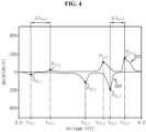
- FIG. 4 is a graph exemplarily showing the third and fourth differential capacity curves corresponding to the third and fourth capacity curves of FIG. 2 with a one-to-one relationship.
- the first differential capacity curve 301 may be determined from the first capacity curve 201.
- the second differential capacity curve 302 may be determined from the second capacity curve 202.
- the third differential capacity curve 303 may be determined from the third capacity curve 203.
- the fourth differential capacity curve 304 may be determined from the fourth capacity curve 204.
- each of the first differential capacity curve 301 and the third differential capacity curve 303 acquired through charging is shown on the upper part of FIGS. 3 and 4
- each of the first to fourth differential capacity curves 301, 302, 303, 304 relies on the electrode materials or the like of the battery B. Accordingly, even though the battery B degrades, the total number (or minimum number) of peaks of each of the first to fourth differential capacity curves 301, 302, 303, 304 may be constant. Each peak refers to the relative maximum point or the relative minimum point.
- the graphs of FIGS. 3 and 4 show that the first differential capacity curve 301 includes peaks P C1_1 , P C1_2 , P C1_3 , the second differential capacity curve 302 includes peaks P D1_1 , P D1_2 , P D1_3 , the third differential capacity curve 303 includes peaks P C2_1 , P C2_2 , P C2_3 , and the fourth differential capacity curve 304 includes peaks P D2_1 , P D2_2 , P D2_3 .
- Each of the peaks P C1_1 , P C1_2 , P C1_3 of the first differential capacity curve 301 may be referred to as a charge feature point of the first differential capacity curve 301.
- the control unit 120 may store charge feature values each indicating voltage values V C1_1 , V C1_2 , V C1_3 of the peaks P C1_1 , P C1_2 , P C1_3 in the memory unit 130.
- Each of the peaks P D1_1 , P D1_2 , P D1_3 of the second differential capacity curve 302 may be referred to as a discharge feature point of the second differential capacity curve 302.
- the control unit 120 may store discharge feature values each indicating voltage values V D1_1 , V D1_2 , V D1_3 of the peaks P D1_1 , P D1_2 , P D1_3 in the memory unit 130.
- Each of the peaks P C2_1 , P C2_2 , P C2_3 of the third differential capacity curve 303 may be referred to as a charge feature point of the third differential capacity curve 303.
- the control unit 120 may store charge feature values each indicating voltage values V C2_1 , V C2_2 , V C2_3 of the peaks P C2_1 , P C2_2 , P C2 _ 3 in the memory unit 130.
- Each of the peaks P D2_1 , P D2_2 , P D2_3 of the fourth differential capacity curve 304 may be referred to as a discharge feature point of the fourth differential capacity curve 304.
- the control unit 120 may store discharge feature values each indicating voltage values V D2_1 , V D2_2 , V D2_3 of the peaks P D2_1 , P D2_2 , P D2_3 in the memory unit 130.
- the first differential capacity curve 301 has the peak C1_1 , the peak C1_2 and the peak C1_3 in the ascending order of the voltage V.
- the second differential capacity curve 302 has the peak D1_1 , the peak D1_2 and the peak D1_3 in the ascending order of the voltage V.
- the third differential capacity curve 303 has the peak C2_1 , the peak C2_2 and the peak C2_3 in the ascending order of the voltage V.
- the fourth differential capacity curve 304 has the peak D2_1 , the peak D2_2 and the peak D2_3 in the ascending order of the voltage V.
- the charge feature value V C2_1 is larger than the charge feature value V C1_1
- the charge feature value V C2_2 is larger than the charge feature value V C1_2
- the charge feature value V C2_3 is larger than the charge feature value V C1_3 .
- the discharge feature value V D2_1 is smaller than the discharge feature value V D1_1
- the discharge feature value V D2_2 is smaller than the discharge feature value V D1_2
- the discharge feature value V D2_3 is smaller than the discharge feature value V D1_3 .
- a voltage difference between the charge feature point and the discharge feature point located in the same order of the third differential capacity curve 303 and the fourth differential capacity curve 304 is larger than a voltage difference between the charge feature point and the discharge feature point located in the same order of the first differential capacity curve 301 and the second differential capacity curve 302.
- a difference between the charge feature value V C2_1 and the discharge feature value V D2_1 is larger than a difference between the charge feature value V C1_1 and the discharge feature value V D1_1 .
- a difference between the charge feature value V C2_2 and the discharge feature value V D2_2 is larger than a difference between the charge feature value V C1_2 and the discharge feature value V D1_2 .
- a difference between the charge feature value V C2_3 and the discharge feature value V D2_3 is larger than a difference between the charge feature value V C1_3 and the discharge feature value V D1_3 .
- FIG. 5 is a flowchart exemplarily showing a battery management method according to a first embodiment of the present disclosure.
- step S500 the control unit 120 determines a first differential capacity curve 301, based on a first voltage history and a first capacity history of the battery B acquired for a first period during which the battery B is charged with a first constant current.
- step S505 the control unit 120 determines a second differential capacity curve 302 based on a second voltage history and a second capacity history of the battery B acquired for a second period during which the battery B is discharged with the first constant current.
- step S510 the control unit 120 determines a third differential capacity curve 303 based on a third voltage history and a third capacity history of the battery B acquired for a third period during which the battery B is charged with a second constant current.
- step S515 the control unit 120 determines a fourth differential capacity curve 304 based on a fourth voltage history and a fourth capacity history of the battery B acquired for a fourth period during which the battery B is discharged with the second constant current.
- the control unit 120 detects a first charge feature point from the first differential capacity curve 301.
- the first charge feature point may be a peak located in a first predetermined order among the peaks P C1_1 , P C1_2 , P C1_3 of the first differential capacity curve 301.
- the first predetermined order may be the first in the ascending order of voltage, and in this case, the peak C1_1 may be determined as the first charge feature point.
- the control unit 120 detects a first discharge feature point from the second differential capacity curve 302.
- the first discharge feature point may be a peak located in the first predetermined order among the peaks P D1_1 , P D1_2 , P D1_3 of the second differential capacity curve 302.
- the peak D1_1 may be determined as the first discharge feature point.
- the control unit 120 detects a second charge feature point from the third differential capacity curve 303.
- the second charge feature point may be a peak located in the first predetermined order among the peaks P C2_1 , P C2_2 , P C2_3 of the third differential capacity curve 303.
- the peak C2_1 may be determined as the second charge feature point.
- step S535 the control unit 120 detects a second discharge feature point from the fourth differential capacity curve 304.
- the second discharge feature point may be a peak located in the first predetermined order among the peaks P D2_1 , P D2_2 , P D2_3 of the fourth differential capacity curve 304.
- the peak D2_1 may be determined as the second discharge feature point.
- the control unit 120 determines degradation information of the battery B based on the first and second charge feature values and the first and second discharge feature values.
- the degradation information includes a first hysteresis value ⁇ V hys1 and a second hysteresis value ⁇ V hys2 .
- the first hysteresis value ⁇ V hys1 indicates an absolute value of difference between the first charge feature value V C1_1 and the first discharge feature value V D1_1 .
- the second hysteresis value ⁇ V hys2 indicates an absolute value of difference between the second charge feature value V C2_1 and the second discharge feature value V D2_1 .
- the degradation information may further include a first difference value which is an absolute value of difference between the first hysteresis value ⁇ V hys1 and the second hysteresis value ⁇ V hys2 .
- step S545 the control unit 120 controls the charge and discharge of the battery B based on the degradation information of the battery B.
- the control unit 120 may decrease a maximum allowable current rate of the battery B, decrease an end-of-charge voltage of the battery B, or increase an end-of-discharge voltage of the battery B.
- the first threshold value may be preset, taking the electrical and chemical properties of the battery B into account.
- the maximum allowable current rate may be a maximum of current rate allowed for the charge and discharge of the battery B.
- the end-of-charge voltage may be a maximum of allowable voltage for the charge of the battery B.
- the end-of-discharge voltage may be a minimum of allowable voltage for the discharge of the battery B.
- the decrease in the maximum allowable current rate, the decrease in the end-of-charge voltage and the increase in the end-of-discharge voltage may be proportional to a ratio of the first difference value to the first threshold value. For example, when the first difference value is 1.1 times larger than the first threshold value, the maximum allowable current rate may decrease at the ratio of 1/1.1 to the previous one.
- FIG. 6 is a flowchart exemplarily showing a battery management method according to a second embodiment of the present disclosure.
- the battery management method according to the second embodiment includes the same steps S500-S535 as the battery management method according to the first embodiment described above with reference to FIG. 5 .
- difference(s) from the battery management method according to the first embodiment will be described.
- the control unit 120 detects a third charge feature point from the first differential capacity curve 301.
- the third charge feature point may be a peak located in a second predetermined order among the peaks P C1_1 , P C1_2 , P C1_3 of the first differential capacity curve 301.
- the second predetermined order may be the third one in the ascending order of voltage, and in this case, the peak C1_3 may be determined as the third charge feature point.
- step S605 the control unit 120 detects a third discharge feature point from the second differential capacity curve 302.
- the third discharge feature point may be a peak located in the second predetermined order among the peaks P D1_1 , P D1_2 , P D1_3 of the second differential capacity curve 302.
- the peak D1_3 may be determined as the third discharge feature point.
- step S610 the control unit 120 detects a fourth charge feature point from the third differential capacity curve 303.
- the fourth charge feature point may be a peak located in the second predetermined order among the peaks P C2_1 , P C2_2 , P C2_3 of the third differential capacity curve 303.
- the peak C2_3 may be determined as the fourth charge feature point.
- the control unit 120 detects a fourth discharge feature point from the fourth differential capacity curve 304.
- the fourth discharge feature point may be a peak located in the second predetermined order among the peaks P D2_1 , P D2_2 , P D2_3 of the fourth differential capacity curve 304.
- the peak D2_3 may be determined as the fourth discharge feature point.
- step S620 the control unit 120 determines degradation information of the battery B based on the first to fourth charge feature values and the first to fourth discharge feature values.
- the degradation information includes first to fourth hysteresis values.
- the third hysteresis value ⁇ V hys3 indicates an absolute value of difference between the third charge feature value V C1_3 and the third discharge feature value V D1_3 .
- the fourth hysteresis value ⁇ V hys4 indicates an absolute value between difference between the fourth charge feature value V C2_3 and the fourth discharge feature value V D2_3 .
- the degradation information may further include a second difference value which is an absolute value of difference between the third hysteresis value ⁇ V hys3 and the fourth hysteresis value ⁇ V hys4 .
- the degradation information may further include a third difference value which is an absolute value of difference between the first hysteresis value ⁇ V hys1 and the third hysteresis value ⁇ V hys3 .
- the degradation information may further include a fourth difference value which is an absolute value of difference between the second hysteresis value ⁇ V hys2 and the fourth hysteresis value ⁇ V hys4 .
- step S625 the control unit 120 controls the charge and discharge of the battery B based on the degradation information of the battery B.
- the control unit 120 may decrease the maximum allowable current rate of the battery B, decrease the end-of-charge voltage of the battery B, or increase the end-of-discharge voltage of the battery B.
- Each of the second to fourth threshold values may be preset, taking the electrical and chemical properties of the battery B into account.
- the decrease in the maximum allowable current rate, the decrease in the end-of-charge voltage and the increase in the end-of-discharge voltage may be proportional to the largest one of a ratio of the first difference value to the first threshold value, a ratio of the second difference value to the second threshold value, a ratio of the third difference value to the third threshold value and a ratio of the fourth difference value to the fourth threshold value.
- the maximum allowable current rate may decrease at the ratio of 1/1.2 to the previous one.
- the control unit 120 may decrease the maximum allowable current rate of the battery B, decrease the end-of-charge voltage of the battery B, or increase the end-of-discharge voltage of the battery B.
- Each of the first and second threshold ranges may be preset, taking the electrical and chemical properties or the like of the battery B into account.
- the decrease in the maximum allowable current rate, the decrease in the end-of-charge voltage and the increase in the end-of-discharge voltage may be proportional to a larger one of a ratio of the second difference value to the first difference value and a ratio of the fourth difference value to the third difference value.
Landscapes
- Engineering & Computer Science (AREA)
- Power Engineering (AREA)
- Physics & Mathematics (AREA)
- General Physics & Mathematics (AREA)
- Life Sciences & Earth Sciences (AREA)
- Mechanical Engineering (AREA)
- Transportation (AREA)
- Sustainable Energy (AREA)
- Sustainable Development (AREA)
- Chemical & Material Sciences (AREA)
- General Chemical & Material Sciences (AREA)
- Electrochemistry (AREA)
- Chemical Kinetics & Catalysis (AREA)
- Manufacturing & Machinery (AREA)
- Microelectronics & Electronic Packaging (AREA)
- Secondary Cells (AREA)
- Charge And Discharge Circuits For Batteries Or The Like (AREA)
- Health & Medical Sciences (AREA)
- General Health & Medical Sciences (AREA)
- Medical Informatics (AREA)
- Tests Of Electric Status Of Batteries (AREA)
Claims (10)
- Appareil de gestion de batterie (100), comprenant :une unité de détection (110) configurée d'une part pour détecter une tension et un courant d'une batterie (B), d'autre part pour émettre un signal de détection indiquant la tension détectée et le courant détecté ; etune unité de contrôle (120) couplée en service à l'unité de détection,l'unité de contrôle étant configurée pour :déterminer une première courbe de la capacité différentielle sur la tension (301) basée sur un premier historique de la tension et un premier historique de la capacité de la batterie saisis pour une première période au cours de laquelle la batterie est chargée avec un premier courant constant,déterminer une deuxième courbe de la capacité différentielle sur la tension (302) basée sur un deuxième historique de la tension et un deuxième historique de la capacité de la batterie saisis pour une deuxième période au cours de laquelle la batterie est déchargée avec le premier courant constant,caractérisé en ce que l'unité de contrôle est configurée en outre pour :déterminer une troisième courbe de la capacité différentielle sur la tension (303) basée sur un troisième historique de la tension et un troisième historique de la capacité de la batterie saisis pour une troisième période au cours de laquelle la batterie est chargée avec un deuxième courant constant différent du premier courant constant,déterminer une quatrième courbe de la capacité différentielle sur la tension (304) basée sur un quatrième historique de la tension et un quatrième historique de la capacité de la batterie saisis pour une quatrième période au cours de laquelle la batterie est déchargée avec le deuxième courant constant,détecter un premier point caractéristique de la charge d'après la première courbe de la capacité différentielle sur la tension, le premier point caractéristique de la charge étant un pic (PC1_1) situé dans un premier ordre prédéterminé parmi des pics de la première courbe de la capacité différentielle sur la tension,détecter un premier point caractéristique de la décharge d'après la deuxième courbe de la capacité différentielle sur la tension, le premier point caractéristique de la décharge étant un pic (PD1_1) situé dans le premier ordre prédéterminé parmi des pics de la deuxième courbe de la capacité différentielle sur la tension,détecter un deuxième point caractéristique de la charge d'après la troisième courbe de la capacité différentielle sur la tension, le deuxième point caractéristique de la charge étant un pic (PC2_1) situé dans le premier ordre prédéterminé parmi des pics de la troisième courbe de la capacité différentielle sur la tension,détecter un deuxième point caractéristique de la décharge d'après la quatrième courbe de la capacité différentielle sur la tension, le deuxième point caractéristique de la décharge étant un pic (PD2_1) situé dans le premier ordre prédéterminé parmi des pics de la quatrième courbe de la capacité différentielle sur la tension, etdéterminer des informations sur la dégradation de la batterie sur la base de première et deuxième valeurs caractéristiques de la charge et de première et deuxième valeurs caractéristiques de la décharge,les première et deuxième valeurs caractéristiques de la charge étant des valeurs de la tension (VC1_1, VC2_1) des premier et deuxième points caractéristiques de la charge respectivement, etles première et deuxième valeurs caractéristiques de la décharge étant des valeurs de la tension (VD1_1, VD2_1) des premier et deuxième points caractéristiques de la décharge respectivement,l'unité de contrôle étant configurée pour :déterminer une première valeur d'hystérésis (ΔVhys1) indiquant une valeur absolue de la différence entre la première valeur caractéristique de la charge et la première valeur caractéristique de la décharge, etdéterminer une deuxième valeur d'hystérésis (ΔVhys2) indiquant une valeur absolue de la différence entre la deuxième valeur caractéristique de la charge et la deuxième valeur caractéristique de la décharge,
etles informations sur la dégradation comprenant les première et deuxième valeurs d'hystérésis. - Appareil de gestion de batterie selon la revendication 1,
les informations sur la dégradation comprenant en outre une première valeur de différence, qui est une valeur absolue de la différence entre la première valeur d'hystérésis et la deuxième valeur d'hystérésis. - Appareil de gestion de batterie selon la revendication 1,
l'unité de contrôle étant configurée en outre pour :détecter un troisième point caractéristique de la charge d'après la première courbe de la capacité différentielle sur la tension,détecter un troisième point caractéristique de la décharge d'après la deuxième courbe de la capacité différentielle sur la tension,détecter un quatrième point caractéristique de la charge d'après la troisième courbe de la capacité différentielle sur la tension,détecter un quatrième point caractéristique de la décharge d'après la quatrième courbe de la capacité différentielle sur la tension,déterminer les informations sur la dégradation de la batterie basées en outre sur des troisième et quatrième valeurs caractéristiques de la charge et des troisième et quatrième valeurs caractéristiques de la décharge,les troisième et quatrième points valeurs caractéristiques de la charge étant des valeurs de tension (Vci _2, VC2_2) des troisième et quatrième points caractéristiques de la charge respectivement, etles troisième et quatrième points valeurs caractéristiques de la décharge étant des valeurs de tension (VD1_2, VD2_2) des troisième et quatrième points caractéristiques de la décharge respectivement. - Appareil de gestion de batterie selon la revendication 3,le troisième point caractéristique de la charge étant un pic (PC1_2) situé dans un deuxième ordre prédéterminé parmi les pics de la première courbe de la capacité différentielle sur la tension,le troisième point caractéristique de la décharge étant un pic (PD1_2) situé dans le deuxième ordre prédéterminé parmi des pics de la deuxième courbe de la capacité différentielle sur la tension,le quatrième point caractéristique de la charge étant un pic (PC2_2) situé dans le deuxième ordre prédéterminé parmi les pics de la troisième courbe de la capacité différentielle sur la tension, etle quatrième point caractéristique de la décharge étant un pic (PD2_2) situé dans le deuxième ordre prédéterminé parmi les pics de la quatrième courbe de la capacité différentielle sur la tension.
- Appareil de gestion de batterie selon la revendication 4,
l'unité de contrôle étant configurée pour :déterminer une troisième valeur d'hystérésis (ΔVhys3) indiquant une valeur absolue de la différence entre la troisième valeur caractéristique de la charge et la troisième valeur caractéristique de la décharge, etdéterminer une quatrième valeur d'hystérésis (ΔVhys4) indiquant une valeur absolue de la différence entre la quatrième valeur caractéristique de la charge et la quatrième valeur caractéristique de la décharge, etles informations sur la dégradation comprenant en outre les troisième et quatrième valeurs d'hystérésis. - Appareil de gestion de batterie selon la revendication 5,
les informations sur la dégradation comprenant en outre au moins une d'une deuxième valeur de différence, qui est une valeur absolue de la différence entre la troisième valeur d'hystérésis et la quatrième valeur d'hystérésis, d'une troisième valeur de différence, qui est une valeur absolue de la différence entre la première valeur d'hystérésis et la troisième valeur d'hystérésis, ou d'une quatrième valeur de différence, qui est une valeur absolue de la différence entre la deuxième valeur d'hystérésis et la quatrième valeur d'hystérésis, - Appareil de gestion de batterie selon la revendication 1, l'unité de contrôle étant configurée pour déterminer un taux maximum admissible pour la charge et la décharge de la batterie, d'après les informations sur la dégradation.
- Pack-batterie comprenant l'appareil de gestion de batterie selon une quelconque des revendications 1 à 7.
- Véhicule électrique comprenant le pack-batterie selon la revendication 8.
- Procédé de gestion de batterie faisant usage de l'appareil de gestion de batterie selon une quelconque des revendications 1 à 7, le procédé de gestion de batterie comprenant :la détermination (S500), par l'unité de contrôle, de la première courbe de la capacité différentielle sur la tension basée sur le premier historique de la tension et le premier historique de la batterie saisis pour la première période au cours de laquelle la batterie est chargée avec le premier courant constant ;la détermination (S505), par l'unité de contrôle, de la deuxième courbe de la capacité différentielle sur la tension basée sur le deuxième historique de la tension et le deuxième historique de la batterie saisis pour la deuxième période au cours de laquelle la batterie est déchargée avec le premier courant constant ;la détermination (S510), par l'unité de contrôle, de la troisième courbe de la capacité différentielle sur la tension basée sur le troisième historique de la tension et le troisième historique de la capacité de la batterie saisis pour la troisième période au cours de laquelle la batterie est chargée avec le deuxième courant constant ;la détermination (S515), par l'unité de contrôle, de la quatrième courbe de la capacité différentielle sur la tension basée sur le quatrième historique de la tension et le quatrième historique de la capacité de la batterie saisis pour la quatrième période au cours de laquelle la batterie est déchargée avec le deuxième courant constant,la détection (S520), par l'unité de contrôle, du premier point caractéristique de la charge d'après la première courbe de la capacité différentielle sur la tension, le premier point caractéristique de la charge étant un pic situé dans un premier ordre prédéterminé parmi des pics de la première courbe de la capacité différentielle ;la détection (S525), par l'unité de contrôle, du premier point caractéristique de la décharge d'après la deuxième courbe de la capacité différentielle sur la tension, le premier point caractéristique de la décharge étant un pic situé dans le premier ordre prédéterminé parmi des pics de la deuxième courbe de la capacité différentielle ;la détection (S530), par l'unité de contrôle, du deuxième point caractéristique de la charge d'après la troisième courbe de la capacité différentielle sur la tension, le deuxième point caractéristique de la charge étant un pic situé dans le premier ordre prédéterminé parmi des pics de la troisième courbe de la capacité différentielle ;la détection (S535), par l'unité de contrôle, du deuxième point caractéristique de la décharge d'après la quatrième courbe de la capacité différentielle sur la tension, le deuxième point caractéristique de la décharge étant un pic situé dans le premier ordre prédéterminé parmi des pics de la quatrième courbe de la capacité différentielle ; etla détermination (S540), par l'unité de contrôle, des informations sur la dégradation basées sur des première et deuxième valeurs caractéristiques de la charge et des première et deuxième valeurs caractéristiques de la décharge,la détermination des informations sur la dégradation comprenant :la détermination, par l'unité de contrôle, d'une première valeur d'hystérésis indiquant une valeur absolue de la différence entre la première valeur caractéristique de la charge et la première valeur caractéristique de la décharge, etla détermination, par l'unité de contrôle, d'une deuxième valeur d'hystérésis indiquant une valeur absolue de la différence entre la deuxième valeur caractéristique de la charge et la deuxième valeur caractéristique de la décharge,les informations sur la dégradation comprenant les première et deuxième valeurs d'hystérésis.
Applications Claiming Priority (2)
| Application Number | Priority Date | Filing Date | Title |
|---|---|---|---|
| KR1020190115464A KR102766401B1 (ko) | 2019-09-19 | 2019-09-19 | 배터리 관리 장치, 배터리 관리 방법, 배터리 팩 및 전기 차량 |
| PCT/KR2020/010918 WO2021054618A1 (fr) | 2019-09-19 | 2020-08-14 | Appareil de gestion de batterie, procédé de gestion de batterie, bloc-batterie et véhicule électrique |
Publications (3)
| Publication Number | Publication Date |
|---|---|
| EP3982141A1 EP3982141A1 (fr) | 2022-04-13 |
| EP3982141A4 EP3982141A4 (fr) | 2022-08-10 |
| EP3982141B1 true EP3982141B1 (fr) | 2024-02-14 |
Family
ID=74883229
Family Applications (1)
| Application Number | Title | Priority Date | Filing Date |
|---|---|---|---|
| EP20866793.1A Active EP3982141B1 (fr) | 2019-09-19 | 2020-08-14 | Appareil de gestion de batterie, procédé de gestion de batterie, bloc-batterie et véhicule électrique |
Country Status (9)
| Country | Link |
|---|---|
| US (1) | US12007449B2 (fr) |
| EP (1) | EP3982141B1 (fr) |
| JP (1) | JP7159524B2 (fr) |
| KR (1) | KR102766401B1 (fr) |
| CN (1) | CN113711461B (fr) |
| ES (1) | ES2975509T3 (fr) |
| HU (1) | HUE065724T2 (fr) |
| PL (1) | PL3982141T3 (fr) |
| WO (1) | WO2021054618A1 (fr) |
Families Citing this family (13)
| Publication number | Priority date | Publication date | Assignee | Title |
|---|---|---|---|---|
| KR102537607B1 (ko) * | 2019-05-14 | 2023-05-25 | 주식회사 엘지에너지솔루션 | 배터리의 퇴화도를 결정하기 위한 장치, 방법 및 배터리 팩 |
| KR102785853B1 (ko) * | 2019-11-15 | 2025-03-21 | 주식회사 엘지에너지솔루션 | 배터리 관리 장치, 배터리 관리 방법 및 배터리 팩 |
| JP2021092404A (ja) * | 2019-12-06 | 2021-06-17 | 株式会社Gsユアサ | 劣化推定装置、劣化推定システム、劣化推定方法、及びコンピュータプログラム |
| KR20210156618A (ko) * | 2020-06-18 | 2021-12-27 | 주식회사 엘지에너지솔루션 | 배터리 관리 시스템, 배터리 관리 방법, 배터리 팩 및 전기 차량 |
| KR102737635B1 (ko) * | 2020-07-20 | 2024-12-02 | 주식회사 엘지에너지솔루션 | 배터리 관리 시스템, 배터리 관리 방법, 배터리 팩 및 전기 차량 |
| US20230096154A1 (en) * | 2021-09-24 | 2023-03-30 | Intel Corporation | Apparatus and method for isolating and discharging a battery |
| US12500436B2 (en) * | 2021-10-20 | 2025-12-16 | China Energy Investment Corporation Limited | Controller, system, and method for managing discharge or charge of heterogeneous battery packs |
| US12210064B2 (en) * | 2022-03-17 | 2025-01-28 | Ricoh Company, Ltd. | Safe state detection method for lithium-ion secondary battery, safe state detection apparatus, power storage device, safe state detection system, and recording medium |
| EP4394998A4 (fr) * | 2022-04-21 | 2025-06-25 | LG Energy Solution, Ltd. | Appareil de commande de batterie et procédé de commande de batterie |
| CN114636943B (zh) * | 2022-05-12 | 2022-08-30 | 中创新航科技股份有限公司 | 电池装置、其检测方法、电池单元的筛选方法及装置 |
| KR102916568B1 (ko) * | 2023-01-05 | 2026-01-22 | 주식회사 엘지에너지솔루션 | 단선 검출 장치 및 이의 동작 방법 |
| EP4733785A1 (fr) * | 2023-08-04 | 2026-04-29 | LG Energy Solution, Ltd. | Appareil de diagnostic d'une propriété de résistance d'une cellule unitaire, procédé de diagnostic associé, et cellule unitaire pour batterie secondaire satisfaisant à une condition spécifique selon le procédé |
| TW202520538A (zh) * | 2023-11-14 | 2025-05-16 | 財團法人工業技術研究院 | 計算電池內短路之阻抗值的運算模組、方法及建立電池參考樣本的方法 |
Family Cites Families (22)
| Publication number | Priority date | Publication date | Assignee | Title |
|---|---|---|---|---|
| US8653793B2 (en) | 2009-09-25 | 2014-02-18 | Toyota Jidosha Kabushiki Kaisha | Secondary battery system |
| EP2838151B1 (fr) | 2012-04-13 | 2017-08-23 | LG Chem, Ltd. | Système de pile rechargeable comprenant un matériau cathode mélangé, et appareil et méthode de gestion de pile rechargeable |
| JP2013247003A (ja) | 2012-05-28 | 2013-12-09 | Sony Corp | 二次電池の充電制御装置、二次電池の充電制御方法、二次電池の充電状態推定装置、二次電池の充電状態推定方法、二次電池の劣化度推定装置、二次電池の劣化度推定方法、及び、二次電池装置 |
| JP5662968B2 (ja) | 2012-06-19 | 2015-02-04 | 株式会社日立製作所 | 二次電池の検査システム、充放電機、及び検査方法 |
| JP5354416B1 (ja) * | 2012-11-05 | 2013-11-27 | 東洋システム株式会社 | 二次電池評価方法および評価プログラム |
| JP2014139897A (ja) | 2013-01-21 | 2014-07-31 | Toyota Industries Corp | 二次電池システム |
| JP2015060761A (ja) | 2013-09-19 | 2015-03-30 | 株式会社東芝 | 二次電池の劣化診断システム及び劣化診断方法 |
| JP6405754B2 (ja) | 2014-07-02 | 2018-10-17 | 日本電気株式会社 | 電池制御装置及び電池制御システム |
| WO2016025552A1 (fr) | 2014-08-12 | 2016-02-18 | The Regents Of The University Of California | Matériau composite à base de sulfure de lithium-oxyde de graphène pour cellules au li/s |
| EP2990818B1 (fr) | 2014-09-01 | 2019-11-27 | Yokogawa Electric Corporation | Système et procédé de mesure de capacité de batterie secondaire |
| JP6123844B2 (ja) | 2014-09-01 | 2017-05-10 | 横河電機株式会社 | 二次電池容量測定システム及び二次電池容量測定方法 |
| JP6485041B2 (ja) * | 2014-12-26 | 2019-03-20 | 株式会社リコー | 蓄電デバイス劣化推定装置、蓄電デバイス劣化推定方法、移動体 |
| JP6380417B2 (ja) * | 2016-01-21 | 2018-08-29 | 横河電機株式会社 | 二次電池容量測定システム及び二次電池容量測定方法 |
| JP6477610B2 (ja) * | 2016-06-22 | 2019-03-06 | 横河電機株式会社 | 二次電池容量測定システムおよび二次電池容量測定方法 |
| KR102447292B1 (ko) | 2016-09-21 | 2022-09-26 | 바스프 토다 배터리 머티리얼스 엘엘씨 | 양극 활물질 및 그 제조 방법, 및 비수전해질 이차 전지 |
| KR102305291B1 (ko) | 2017-02-10 | 2021-09-29 | 닛산 노쓰 아메리카, 인크. | 자율주행 차량 운용 관리 |
| JP2018147635A (ja) | 2017-03-03 | 2018-09-20 | 住友金属鉱山株式会社 | 二次電池用正極活物質の評価方法 |
| JP2018205139A (ja) * | 2017-06-05 | 2018-12-27 | 三菱自動車工業株式会社 | 二次電池システム |
| JP6477957B2 (ja) | 2017-07-19 | 2019-03-06 | 株式会社Gsユアサ | 推定装置、蓄電装置、推定方法、及びコンピュータプログラム |
| JP2019045351A (ja) * | 2017-09-04 | 2019-03-22 | 三菱自動車工業株式会社 | 二次電池システム |
| TWI657639B (zh) * | 2017-12-04 | 2019-04-21 | Industrial Technology Research Institute | 電池放電流程決定方法和系統 |
| CN110031770B (zh) * | 2019-04-29 | 2021-08-17 | 上海玫克生储能科技有限公司 | 一种快速得到电池包中所有单体电池容量的方法 |
-
2019
- 2019-09-19 KR KR1020190115464A patent/KR102766401B1/ko active Active
-
2020
- 2020-08-14 HU HUE20866793A patent/HUE065724T2/hu unknown
- 2020-08-14 CN CN202080029169.3A patent/CN113711461B/zh active Active
- 2020-08-14 PL PL20866793.1T patent/PL3982141T3/pl unknown
- 2020-08-14 ES ES20866793T patent/ES2975509T3/es active Active
- 2020-08-14 JP JP2021546327A patent/JP7159524B2/ja active Active
- 2020-08-14 EP EP20866793.1A patent/EP3982141B1/fr active Active
- 2020-08-14 US US17/440,905 patent/US12007449B2/en active Active
- 2020-08-14 WO PCT/KR2020/010918 patent/WO2021054618A1/fr not_active Ceased
Also Published As
| Publication number | Publication date |
|---|---|
| WO2021054618A1 (fr) | 2021-03-25 |
| US20220158468A1 (en) | 2022-05-19 |
| HUE065724T2 (hu) | 2024-06-28 |
| CN113711461B (zh) | 2023-11-21 |
| US12007449B2 (en) | 2024-06-11 |
| EP3982141A1 (fr) | 2022-04-13 |
| KR102766401B1 (ko) | 2025-02-10 |
| CN113711461A (zh) | 2021-11-26 |
| KR20210033764A (ko) | 2021-03-29 |
| PL3982141T3 (pl) | 2024-05-13 |
| EP3982141A4 (fr) | 2022-08-10 |
| ES2975509T3 (es) | 2024-07-08 |
| JP2022520765A (ja) | 2022-04-01 |
| JP7159524B2 (ja) | 2022-10-25 |
Similar Documents
| Publication | Publication Date | Title |
|---|---|---|
| EP3982141B1 (fr) | Appareil de gestion de batterie, procédé de gestion de batterie, bloc-batterie et véhicule électrique | |
| US12370922B2 (en) | Battery management apparatus, battery management method, battery pack, and electric vehicle | |
| EP3913385B1 (fr) | Appareil et méthode pour déterminer le degré de dégradation d'une batterie et d'un bloc-batterie comprenant l'appareil | |
| US11460506B2 (en) | Apparatus and method for determining differential voltage curve of battery and battery pack comprising the apparatus | |
| EP4053573B1 (fr) | Système de gestion de batterie, bloc-batterie, véhicule électrique et procédé de gestion de batterie | |
| US12203996B2 (en) | Battery management system, battery pack, electric vehicle and battery management method | |
| EP4725752A2 (fr) | Système de gestion de batterie, procédé de gestion de batterie, bloc-batterie et véhicule électrique | |
| EP4156376B1 (fr) | Système de gestion de batterie, procédé de gestion de batterie, bloc-batterie et véhicule électrique | |
| US12322766B2 (en) | Battery management system, battery pack, electric vehicle and battery management method | |
| EP4166956A1 (fr) | Dispositif de diagnostic de batterie, procédé de diagnostic de batterie, bloc-batterie et véhicule électrique | |
| US12344120B2 (en) | Battery management system, battery management method, battery pack, and electric vehicle | |
| US20260048680A1 (en) | Battery Management System, Battery Management Method, Battery Pack, and Electric Vehicle |
Legal Events
| Date | Code | Title | Description |
|---|---|---|---|
| STAA | Information on the status of an ep patent application or granted ep patent |
Free format text: STATUS: THE INTERNATIONAL PUBLICATION HAS BEEN MADE |
|
| PUAI | Public reference made under article 153(3) epc to a published international application that has entered the european phase |
Free format text: ORIGINAL CODE: 0009012 |
|
| STAA | Information on the status of an ep patent application or granted ep patent |
Free format text: STATUS: REQUEST FOR EXAMINATION WAS MADE |
|
| 17P | Request for examination filed |
Effective date: 20220104 |
|
| AK | Designated contracting states |
Kind code of ref document: A1 Designated state(s): AL AT BE BG CH CY CZ DE DK EE ES FI FR GB GR HR HU IE IS IT LI LT LU LV MC MK MT NL NO PL PT RO RS SE SI SK SM TR |
|
| A4 | Supplementary search report drawn up and despatched |
Effective date: 20220708 |
|
| RIC1 | Information provided on ipc code assigned before grant |
Ipc: G01R 31/382 20190101ALI20220704BHEP Ipc: B60L 58/18 20190101ALI20220704BHEP Ipc: G01R 31/36 20200101ALI20220704BHEP Ipc: G01R 31/3842 20190101ALI20220704BHEP Ipc: G01R 31/392 20190101AFI20220704BHEP |
|
| DAV | Request for validation of the european patent (deleted) | ||
| DAX | Request for extension of the european patent (deleted) | ||
| REG | Reference to a national code |
Ref country code: DE Ref legal event code: R079 Free format text: PREVIOUS MAIN CLASS: G01R0031392000 Ipc: G01R0031360000 Ref country code: DE Ref legal event code: R079 Ref document number: 602020025839 Country of ref document: DE Free format text: PREVIOUS MAIN CLASS: G01R0031392000 Ipc: G01R0031360000 |
|
| GRAP | Despatch of communication of intention to grant a patent |
Free format text: ORIGINAL CODE: EPIDOSNIGR1 |
|
| STAA | Information on the status of an ep patent application or granted ep patent |
Free format text: STATUS: GRANT OF PATENT IS INTENDED |
|
| RIC1 | Information provided on ipc code assigned before grant |
Ipc: H02J 7/00 20060101ALI20230915BHEP Ipc: B60L 58/16 20190101ALI20230915BHEP Ipc: B60L 58/12 20190101ALI20230915BHEP Ipc: B60L 58/18 20190101ALI20230915BHEP Ipc: B60L 3/12 20060101ALI20230915BHEP Ipc: G01R 31/3842 20190101ALI20230915BHEP Ipc: G01R 31/382 20190101ALI20230915BHEP Ipc: G01R 31/392 20190101ALI20230915BHEP Ipc: G01R 31/36 20200101AFI20230915BHEP |
|
| INTG | Intention to grant announced |
Effective date: 20231020 |
|
| P01 | Opt-out of the competence of the unified patent court (upc) registered |
Effective date: 20231030 |
|
| GRAS | Grant fee paid |
Free format text: ORIGINAL CODE: EPIDOSNIGR3 |
|
| GRAA | (expected) grant |
Free format text: ORIGINAL CODE: 0009210 |
|
| STAA | Information on the status of an ep patent application or granted ep patent |
Free format text: STATUS: THE PATENT HAS BEEN GRANTED |
|
| AK | Designated contracting states |
Kind code of ref document: B1 Designated state(s): AL AT BE BG CH CY CZ DE DK EE ES FI FR GB GR HR HU IE IS IT LI LT LU LV MC MK MT NL NO PL PT RO RS SE SI SK SM TR |
|
| REG | Reference to a national code |
Ref country code: GB Ref legal event code: FG4D |
|
| REG | Reference to a national code |
Ref country code: CH Ref legal event code: EP |
|
| REG | Reference to a national code |
Ref country code: NL Ref legal event code: FP |
|
| REG | Reference to a national code |
Ref country code: DE Ref legal event code: R096 Ref document number: 602020025839 Country of ref document: DE |
|
| REG | Reference to a national code |
Ref country code: IE Ref legal event code: FG4D |
|
| REG | Reference to a national code |
Ref country code: SE Ref legal event code: TRGR |
|
| REG | Reference to a national code |
Ref country code: LT Ref legal event code: MG9D |
|
| REG | Reference to a national code |
Ref country code: HU Ref legal event code: AG4A Ref document number: E065724 Country of ref document: HU |
|
| PG25 | Lapsed in a contracting state [announced via postgrant information from national office to epo] |
Ref country code: IS Free format text: LAPSE BECAUSE OF FAILURE TO SUBMIT A TRANSLATION OF THE DESCRIPTION OR TO PAY THE FEE WITHIN THE PRESCRIBED TIME-LIMIT Effective date: 20240614 |
|
| REG | Reference to a national code |
Ref country code: ES Ref legal event code: FG2A Ref document number: 2975509 Country of ref document: ES Kind code of ref document: T3 Effective date: 20240708 |
|
| PG25 | Lapsed in a contracting state [announced via postgrant information from national office to epo] |
Ref country code: LT Free format text: LAPSE BECAUSE OF FAILURE TO SUBMIT A TRANSLATION OF THE DESCRIPTION OR TO PAY THE FEE WITHIN THE PRESCRIBED TIME-LIMIT Effective date: 20240214 |
|
| PG25 | Lapsed in a contracting state [announced via postgrant information from national office to epo] |
Ref country code: GR Free format text: LAPSE BECAUSE OF FAILURE TO SUBMIT A TRANSLATION OF THE DESCRIPTION OR TO PAY THE FEE WITHIN THE PRESCRIBED TIME-LIMIT Effective date: 20240515 |
|
| REG | Reference to a national code |
Ref country code: AT Ref legal event code: MK05 Ref document number: 1657461 Country of ref document: AT Kind code of ref document: T Effective date: 20240214 |
|
| PG25 | Lapsed in a contracting state [announced via postgrant information from national office to epo] |
Ref country code: HR Free format text: LAPSE BECAUSE OF FAILURE TO SUBMIT A TRANSLATION OF THE DESCRIPTION OR TO PAY THE FEE WITHIN THE PRESCRIBED TIME-LIMIT Effective date: 20240214 Ref country code: RS Free format text: LAPSE BECAUSE OF FAILURE TO SUBMIT A TRANSLATION OF THE DESCRIPTION OR TO PAY THE FEE WITHIN THE PRESCRIBED TIME-LIMIT Effective date: 20240514 |
|
| PG25 | Lapsed in a contracting state [announced via postgrant information from national office to epo] |
Ref country code: AT Free format text: LAPSE BECAUSE OF FAILURE TO SUBMIT A TRANSLATION OF THE DESCRIPTION OR TO PAY THE FEE WITHIN THE PRESCRIBED TIME-LIMIT Effective date: 20240214 |
|
| PG25 | Lapsed in a contracting state [announced via postgrant information from national office to epo] |
Ref country code: RS Free format text: LAPSE BECAUSE OF FAILURE TO SUBMIT A TRANSLATION OF THE DESCRIPTION OR TO PAY THE FEE WITHIN THE PRESCRIBED TIME-LIMIT Effective date: 20240514 Ref country code: NO Free format text: LAPSE BECAUSE OF FAILURE TO SUBMIT A TRANSLATION OF THE DESCRIPTION OR TO PAY THE FEE WITHIN THE PRESCRIBED TIME-LIMIT Effective date: 20240514 Ref country code: LT Free format text: LAPSE BECAUSE OF FAILURE TO SUBMIT A TRANSLATION OF THE DESCRIPTION OR TO PAY THE FEE WITHIN THE PRESCRIBED TIME-LIMIT Effective date: 20240214 Ref country code: IS Free format text: LAPSE BECAUSE OF FAILURE TO SUBMIT A TRANSLATION OF THE DESCRIPTION OR TO PAY THE FEE WITHIN THE PRESCRIBED TIME-LIMIT Effective date: 20240614 Ref country code: HR Free format text: LAPSE BECAUSE OF FAILURE TO SUBMIT A TRANSLATION OF THE DESCRIPTION OR TO PAY THE FEE WITHIN THE PRESCRIBED TIME-LIMIT Effective date: 20240214 Ref country code: GR Free format text: LAPSE BECAUSE OF FAILURE TO SUBMIT A TRANSLATION OF THE DESCRIPTION OR TO PAY THE FEE WITHIN THE PRESCRIBED TIME-LIMIT Effective date: 20240515 Ref country code: FI Free format text: LAPSE BECAUSE OF FAILURE TO SUBMIT A TRANSLATION OF THE DESCRIPTION OR TO PAY THE FEE WITHIN THE PRESCRIBED TIME-LIMIT Effective date: 20240214 Ref country code: BG Free format text: LAPSE BECAUSE OF FAILURE TO SUBMIT A TRANSLATION OF THE DESCRIPTION OR TO PAY THE FEE WITHIN THE PRESCRIBED TIME-LIMIT Effective date: 20240214 Ref country code: AT Free format text: LAPSE BECAUSE OF FAILURE TO SUBMIT A TRANSLATION OF THE DESCRIPTION OR TO PAY THE FEE WITHIN THE PRESCRIBED TIME-LIMIT Effective date: 20240214 |
|
| PG25 | Lapsed in a contracting state [announced via postgrant information from national office to epo] |
Ref country code: PT Free format text: LAPSE BECAUSE OF FAILURE TO SUBMIT A TRANSLATION OF THE DESCRIPTION OR TO PAY THE FEE WITHIN THE PRESCRIBED TIME-LIMIT Effective date: 20240614 |
|
| PG25 | Lapsed in a contracting state [announced via postgrant information from national office to epo] |
Ref country code: PT Free format text: LAPSE BECAUSE OF FAILURE TO SUBMIT A TRANSLATION OF THE DESCRIPTION OR TO PAY THE FEE WITHIN THE PRESCRIBED TIME-LIMIT Effective date: 20240614 Ref country code: LV Free format text: LAPSE BECAUSE OF FAILURE TO SUBMIT A TRANSLATION OF THE DESCRIPTION OR TO PAY THE FEE WITHIN THE PRESCRIBED TIME-LIMIT Effective date: 20240214 |
|
| PG25 | Lapsed in a contracting state [announced via postgrant information from national office to epo] |
Ref country code: DK Free format text: LAPSE BECAUSE OF FAILURE TO SUBMIT A TRANSLATION OF THE DESCRIPTION OR TO PAY THE FEE WITHIN THE PRESCRIBED TIME-LIMIT Effective date: 20240214 |
|
| PG25 | Lapsed in a contracting state [announced via postgrant information from national office to epo] |
Ref country code: SM Free format text: LAPSE BECAUSE OF FAILURE TO SUBMIT A TRANSLATION OF THE DESCRIPTION OR TO PAY THE FEE WITHIN THE PRESCRIBED TIME-LIMIT Effective date: 20240214 |
|
| PG25 | Lapsed in a contracting state [announced via postgrant information from national office to epo] |
Ref country code: EE Free format text: LAPSE BECAUSE OF FAILURE TO SUBMIT A TRANSLATION OF THE DESCRIPTION OR TO PAY THE FEE WITHIN THE PRESCRIBED TIME-LIMIT Effective date: 20240214 Ref country code: CZ Free format text: LAPSE BECAUSE OF FAILURE TO SUBMIT A TRANSLATION OF THE DESCRIPTION OR TO PAY THE FEE WITHIN THE PRESCRIBED TIME-LIMIT Effective date: 20240214 |
|
| PG25 | Lapsed in a contracting state [announced via postgrant information from national office to epo] |
Ref country code: SK Free format text: LAPSE BECAUSE OF FAILURE TO SUBMIT A TRANSLATION OF THE DESCRIPTION OR TO PAY THE FEE WITHIN THE PRESCRIBED TIME-LIMIT Effective date: 20240214 |
|
| PG25 | Lapsed in a contracting state [announced via postgrant information from national office to epo] |
Ref country code: SM Free format text: LAPSE BECAUSE OF FAILURE TO SUBMIT A TRANSLATION OF THE DESCRIPTION OR TO PAY THE FEE WITHIN THE PRESCRIBED TIME-LIMIT Effective date: 20240214 Ref country code: SK Free format text: LAPSE BECAUSE OF FAILURE TO SUBMIT A TRANSLATION OF THE DESCRIPTION OR TO PAY THE FEE WITHIN THE PRESCRIBED TIME-LIMIT Effective date: 20240214 Ref country code: RO Free format text: LAPSE BECAUSE OF FAILURE TO SUBMIT A TRANSLATION OF THE DESCRIPTION OR TO PAY THE FEE WITHIN THE PRESCRIBED TIME-LIMIT Effective date: 20240214 Ref country code: EE Free format text: LAPSE BECAUSE OF FAILURE TO SUBMIT A TRANSLATION OF THE DESCRIPTION OR TO PAY THE FEE WITHIN THE PRESCRIBED TIME-LIMIT Effective date: 20240214 Ref country code: DK Free format text: LAPSE BECAUSE OF FAILURE TO SUBMIT A TRANSLATION OF THE DESCRIPTION OR TO PAY THE FEE WITHIN THE PRESCRIBED TIME-LIMIT Effective date: 20240214 Ref country code: CZ Free format text: LAPSE BECAUSE OF FAILURE TO SUBMIT A TRANSLATION OF THE DESCRIPTION OR TO PAY THE FEE WITHIN THE PRESCRIBED TIME-LIMIT Effective date: 20240214 |
|
| REG | Reference to a national code |
Ref country code: DE Ref legal event code: R097 Ref document number: 602020025839 Country of ref document: DE |
|
| PLBE | No opposition filed within time limit |
Free format text: ORIGINAL CODE: 0009261 |
|
| STAA | Information on the status of an ep patent application or granted ep patent |
Free format text: STATUS: NO OPPOSITION FILED WITHIN TIME LIMIT |
|
| 26N | No opposition filed |
Effective date: 20241115 |
|
| REG | Reference to a national code |
Ref country code: CH Ref legal event code: PL |
|
| PG25 | Lapsed in a contracting state [announced via postgrant information from national office to epo] |
Ref country code: LU Free format text: LAPSE BECAUSE OF NON-PAYMENT OF DUE FEES Effective date: 20240814 |
|
| PG25 | Lapsed in a contracting state [announced via postgrant information from national office to epo] |
Ref country code: MC Free format text: LAPSE BECAUSE OF FAILURE TO SUBMIT A TRANSLATION OF THE DESCRIPTION OR TO PAY THE FEE WITHIN THE PRESCRIBED TIME-LIMIT Effective date: 20240214 Ref country code: SI Free format text: LAPSE BECAUSE OF FAILURE TO SUBMIT A TRANSLATION OF THE DESCRIPTION OR TO PAY THE FEE WITHIN THE PRESCRIBED TIME-LIMIT Effective date: 20240214 Ref country code: CH Free format text: LAPSE BECAUSE OF NON-PAYMENT OF DUE FEES Effective date: 20240831 |
|
| REG | Reference to a national code |
Ref country code: BE Ref legal event code: MM Effective date: 20240831 |
|
| PG25 | Lapsed in a contracting state [announced via postgrant information from national office to epo] |
Ref country code: BE Free format text: LAPSE BECAUSE OF NON-PAYMENT OF DUE FEES Effective date: 20240831 |
|
| PG25 | Lapsed in a contracting state [announced via postgrant information from national office to epo] |
Ref country code: IE Free format text: LAPSE BECAUSE OF NON-PAYMENT OF DUE FEES Effective date: 20240814 |
|
| PGFP | Annual fee paid to national office [announced via postgrant information from national office to epo] |
Ref country code: NL Payment date: 20250722 Year of fee payment: 6 |
|
| PGFP | Annual fee paid to national office [announced via postgrant information from national office to epo] |
Ref country code: HU Payment date: 20250827 Year of fee payment: 6 |
|
| PGFP | Annual fee paid to national office [announced via postgrant information from national office to epo] |
Ref country code: ES Payment date: 20250911 Year of fee payment: 6 |
|
| PGFP | Annual fee paid to national office [announced via postgrant information from national office to epo] |
Ref country code: DE Payment date: 20250721 Year of fee payment: 6 |
|
| PGFP | Annual fee paid to national office [announced via postgrant information from national office to epo] |
Ref country code: TR Payment date: 20250723 Year of fee payment: 6 Ref country code: PL Payment date: 20250723 Year of fee payment: 6 Ref country code: IT Payment date: 20250722 Year of fee payment: 6 |
|
| PGFP | Annual fee paid to national office [announced via postgrant information from national office to epo] |
Ref country code: GB Payment date: 20250722 Year of fee payment: 6 |
|
| PGFP | Annual fee paid to national office [announced via postgrant information from national office to epo] |
Ref country code: FR Payment date: 20250725 Year of fee payment: 6 |
|
| PGFP | Annual fee paid to national office [announced via postgrant information from national office to epo] |
Ref country code: SE Payment date: 20250722 Year of fee payment: 6 |
|
| PG25 | Lapsed in a contracting state [announced via postgrant information from national office to epo] |
Ref country code: CY Free format text: LAPSE BECAUSE OF FAILURE TO SUBMIT A TRANSLATION OF THE DESCRIPTION OR TO PAY THE FEE WITHIN THE PRESCRIBED TIME-LIMIT; INVALID AB INITIO Effective date: 20200814 |