EP3982802B1 - Verstellbare kopplungsvorrichtung und verfahren zur kopplung eines bildschirms oder eines paneels an eine struktur - Google Patents
Verstellbare kopplungsvorrichtung und verfahren zur kopplung eines bildschirms oder eines paneels an eine struktur Download PDFInfo
- Publication number
- EP3982802B1 EP3982802B1 EP20732873.3A EP20732873A EP3982802B1 EP 3982802 B1 EP3982802 B1 EP 3982802B1 EP 20732873 A EP20732873 A EP 20732873A EP 3982802 B1 EP3982802 B1 EP 3982802B1
- Authority
- EP
- European Patent Office
- Prior art keywords
- mounting member
- fastener
- slot
- end wall
- extending
- Prior art date
- Legal status (The legal status is an assumption and is not a legal conclusion. Google has not performed a legal analysis and makes no representation as to the accuracy of the status listed.)
- Active
Links
Images



Classifications
-
- A—HUMAN NECESSITIES
- A47—FURNITURE; DOMESTIC ARTICLES OR APPLIANCES; COFFEE MILLS; SPICE MILLS; SUCTION CLEANERS IN GENERAL
- A47K—SANITARY EQUIPMENT; ACCESSORIES THEREFOR, e.g. TOILET ACCESSORIES
- A47K3/00—Baths; Showers; Appurtenances therefor
- A47K3/28—Showers or bathing douches
- A47K3/30—Screens or collapsible cabinets for showers or baths
- A47K3/302—Screens or collapsible cabinets for showers or baths splash guards
-
- A—HUMAN NECESSITIES
- A47—FURNITURE; DOMESTIC ARTICLES OR APPLIANCES; COFFEE MILLS; SPICE MILLS; SUCTION CLEANERS IN GENERAL
- A47K—SANITARY EQUIPMENT; ACCESSORIES THEREFOR, e.g. TOILET ACCESSORIES
- A47K3/00—Baths; Showers; Appurtenances therefor
- A47K3/28—Showers or bathing douches
- A47K3/30—Screens or collapsible cabinets for showers or baths
- A47K2003/307—Adjustable connections to the wall
-
- E—FIXED CONSTRUCTIONS
- E05—LOCKS; KEYS; WINDOW OR DOOR FITTINGS; SAFES
- E05Y—INDEXING SCHEME ASSOCIATED WITH SUBCLASSES E05D AND E05F, RELATING TO CONSTRUCTION ELEMENTS, ELECTRIC CONTROL, POWER SUPPLY, POWER SIGNAL OR TRANSMISSION, USER INTERFACES, MOUNTING OR COUPLING, DETAILS, ACCESSORIES, AUXILIARY OPERATIONS NOT OTHERWISE PROVIDED FOR, APPLICATION THEREOF
- E05Y2600/00—Mounting or coupling arrangements for elements provided for in this subclass
- E05Y2600/10—Adjustable
- E05Y2600/30—Adjustment motion
- E05Y2600/31—Linear motion
- E05Y2600/312—Horizontal motion
-
- E—FIXED CONSTRUCTIONS
- E05—LOCKS; KEYS; WINDOW OR DOOR FITTINGS; SAFES
- E05Y—INDEXING SCHEME ASSOCIATED WITH SUBCLASSES E05D AND E05F, RELATING TO CONSTRUCTION ELEMENTS, ELECTRIC CONTROL, POWER SUPPLY, POWER SIGNAL OR TRANSMISSION, USER INTERFACES, MOUNTING OR COUPLING, DETAILS, ACCESSORIES, AUXILIARY OPERATIONS NOT OTHERWISE PROVIDED FOR, APPLICATION THEREOF
- E05Y2600/00—Mounting or coupling arrangements for elements provided for in this subclass
- E05Y2600/10—Adjustable
- E05Y2600/30—Adjustment motion
- E05Y2600/31—Linear motion
- E05Y2600/314—Vertical motion
-
- E—FIXED CONSTRUCTIONS
- E06—DOORS, WINDOWS, SHUTTERS, OR ROLLER BLINDS IN GENERAL; LADDERS
- E06B—FIXED OR MOVABLE CLOSURES FOR OPENINGS IN BUILDINGS, VEHICLES, FENCES OR LIKE ENCLOSURES IN GENERAL, e.g. DOORS, WINDOWS, BLINDS, GATES
- E06B3/00—Window sashes, door leaves, or like elements for closing wall or like openings; Layout of fixed or moving closures, e.g. windows in wall or like openings; Features of rigidly-mounted outer frames relating to the mounting of wing frames
- E06B3/54—Fixing of glass panes or like plates
- E06B3/5454—Fixing of glass panes or like plates inside U-shaped section members
-
- E—FIXED CONSTRUCTIONS
- E06—DOORS, WINDOWS, SHUTTERS, OR ROLLER BLINDS IN GENERAL; LADDERS
- E06B—FIXED OR MOVABLE CLOSURES FOR OPENINGS IN BUILDINGS, VEHICLES, FENCES OR LIKE ENCLOSURES IN GENERAL, e.g. DOORS, WINDOWS, BLINDS, GATES
- E06B3/00—Window sashes, door leaves, or like elements for closing wall or like openings; Layout of fixed or moving closures, e.g. windows in wall or like openings; Features of rigidly-mounted outer frames relating to the mounting of wing frames
- E06B3/54—Fixing of glass panes or like plates
- E06B3/549—Fixing of glass panes or like plates by clamping the pane between two subframes
Definitions
- the present invention relates to an adjustable coupling apparatus and a method for coupling a screen or a panel to a structure, and in particular, though not limited to an adjustable coupling apparatus and a method for coupling a screen or a panel of a shower enclosure to a wall, or for coupling a screen or a panel to a wall above a bath for defining a shower enclosure with the bath.
- shower enclosures There are many types of shower enclosures, the majority of which are formed by three walls surrounding a shower base, or a floor configured to drain water from the shower, and a door which essentially forms all or a part of a fourth wall of the enclosure, although in some shower enclosures, the area which would form the fourth wall is left open, particularly in the case of a shower in a wet room.
- at least one and in some cases two of the walls of the shower enclosure to be formed by structural walls of a building, which may be either masonry walls or studded partition walls which typically, are tiled, or are coated with other suitable water protective coatings.
- the third or the second and third walls of the shower enclosure are typically formed by a screen or a panel, typically, of a toughened glass.
- the glass panel or panels are secured to the structural wall or walls by an elongated mounting member which typically, is of channel shape for receiving the screen or panel, or a frame element of the screen or panel for in turn securing the screen or panel to the structural wall.
- the elongated mounting member should be vertically aligned in order that the screen or glass panel when secured to the structural wall by the mounting member is also vertically aligned.
- fasteners typically, screws engaged in plugged drilled holes.
- This is also a problem when securing a screen or panel to a wall above a side of a bath in order to define a shower enclosure above the bath.
- the screw accommodating openings in such mounting members do not accurately align with holes which had already been drilled for the mounting member of the screen or panel which is being replaced. This, thus, requires the drilling of new holes in the structural wall and thereby leaving the existing holes unused with the possibility of moisture leaking into the holes resulting in deterioration of the structural wall, particularly, in cases where the structural wall is a studded partition wall, or a masonry wall which has been studded.
- European Patent Specification No. 1,547,503 of Harrison discloses a mounting member for mounting a panel to a wall.
- the mounting member is of channel shape construction comprising an elongated end wall and a pair of spaced apart elongated side walls extending along and from the end wall and defining with the end wall an elongated channel for receiving the panel therein.
- One or more holes extend through the end wall for accommodating a fastener such as a screw for securing the mounting member to the wall.
- a protector for protecting the panel within the mounting member comprises a rear portion for abutting the end wall of the mounting member.
- a hole extending through the rear portion of the protector is alignable with one of the holes extending through the end wall of the mounting member for accommodating a fastener, such as a screw therethrough for securing the protector and the mounting member to the structure.
- Side springs extending from opposite sides of the rear portion of the protector are slideably engageable in longitudinally extending grooves extending along the side walls of the mounting member.
- the present invention is directed towards providing an adjustable coupling apparatus and a method for coupling a screen or a panel to a structure.
- the invention is also directed towards a structure comprising the adjustable coupling apparatus, and the invention is further directed towards a shower enclosure.
- an adjustable coupling apparatus for coupling a screen or a panel to a structure
- the coupling apparatus comprising an elongated mounting member for mounting on the structure, the mounting member being of channel shape construction and comprising an elongated end wall, and a pair of spaced apart elongated side walls extending along and from the end wall and defining with the end wall an elongated channel configured to receive the screen or panel therein between the side walls, at least one main aperture extending through the end wall, a fastener accommodating element having a secondary aperture extending therethrough located in the channel, and a retaining means for retaining the fastener accommodating element in the channel with the secondary aperture located relative to the main aperture for accommodating a fastener through the secondary aperture and the main aperture to the structure, wherein the retaining means is configured to permit the fastener accommodating element to be slideable longitudinally in the channel, the at least one main aperture comprises an elongated main slot extending longitudinally along the end wall of the mounting member, the main slot being of length in
- the main slot is of width in the transverse direction to allow adjustment of a fastener transversely in the main slot.
- the main slot is of width in the transverse direction sufficient to accommodate adjustment of a fastener in the secondary slot along the entire length of the secondary slot.
- the secondary slot is of width just greater than the maximum dimension of a shank of a fastener.
- the secondary slot comprises a countersunk secondary slot.
- the retaining means comprises at least one pair of interengageable complementary formations, one of the interengageable complementary formations being located on the mounting member, and the other one of the interengageable complementary formations being located on the fastener accommodating element.
- one of the interengageable complementary formations extends from the mounting member, and preferably, extends from the mounting member into the channel.
- the interengageable complementary formation located on the mounting member comprises an elongated retaining track extending longitudinally in the channel, and advantageously, the elongated retaining track extends from the end wall of the mounting member.
- the interengageable complementary formation on the fastener accommodating element comprises a retaining recess extending into the fastener accommodating element, and preferably, the retaining recess is engageable with the interengageable complementary formation extending from the mounting member, and advantageously, the retaining recess is slideably engageable with the interengageable complementary formation extending from the mounting member.
- interengageable complementary formations are configured to engage each other with a snap-fit action.
- a pair of the retaining tracks are provided, the retaining tracks being spaced apart from each other and extending parallel to each other.
- a pair of the retaining recesses are provided, and preferably, the retaining recesses are spaced apart from each other and extend parallel to each other.
- the retaining recesses of the fastener accommodating element are configured to slideably engage the corresponding ones of the retaining tracks.
- each retaining track terminates along a distal edge thereof in an engagement element extending longitudinally along the retaining track and transversely from the retaining track.
- the engagement elements extend transversely from the respective retaining tracks one of towards each other and away from each other.
- the engagement elements extend transversely from the respective retaining tracks towards each other.
- each retaining recess terminates in the fastener accommodating element in an engagement recess for engaging the engagement element of the corresponding retaining track.
- the engagement recess of each retaining recess extends in a generally longitudinal direction relative to the retaining recess and transversely thereof.
- the engagement recesses extend transversely from the respective retaining recesses one of towards each other and away from each other, and advantageously, the engagement recesses extend transversely from the respective retaining recesses away from each other.
- the mounting member defines a structure abutment face for abutting the structure.
- the structure abutment face is located adjacent the end wall, and advantageously, the structure abutment face is located adjacent an outer face of the end wall.
- the fastener accommodating element defines a first abutment face for abutting an inner face of the end wall of the mounting member.
- an abutment portion of the fastener accommodating element extends through the main slot, and preferably, the abutment portion of the fastener accommodating element terminates in a second abutment face for abutting the structure.
- the spacing between the first abutment face of the fastener accommodating element and the second abutment face of the fastener accommodating element is substantially similar to the spacing between the inner face of the end wall of the mounting member and the structure abutment face of the mounting member, and preferably, the spacing between the first abutment face of the fastener accommodating element and the second abutment face of the fastener accommodating element is just less than the spacing between the inner face of the end wall of the mounting member and the structure abutment face of the mounting member.
- the spacing between the first abutment face of the fastener accommodating element and the second abutment face of the fastener accommodating element is less than 2mm less than the spacing between the inner face of the end wall of the mounting member and the structure abutment face of the mounting member, and advantageously, is less than 1 mm, and ideally, less than 0.5mm less than the spacing between the inner face of the end wall of the mounting member and the structure abutment face of the mounting member.
- each retaining track extends at least the length of the main slot, and advantageously, each retaining track extends the length of the mounting member.
- a plurality of longitudinally extending main slots extend through the end wall, the main slots being longitudinally spaced apart along the end wall.
- at least one fastener accommodating element is provided corresponding to each main slot.
- the invention also provides a structure comprising the adjustable coupling apparatus according to the invention secured to the structure by a fastener extending through the secondary slot in the fastener accommodating element.
- a plurality of fasteners are provided through the secondary slots in respective ones of the fastener accommodating elements and one or more corresponding main slots through the end wall for securing the mounting member to the structure.
- one of a panel and a screen is secured to the structure by the adjustable coupling apparatus with the one of the panel and the screen engaged in the channel of the mounting member.
- the structure comprises a wall
- the wall comprises one of a masonry wall and a studded wall
- the structure comprises a wall of a shower enclosure.
- the invention further provides a shower enclosure comprising a panel defining a wall of the shower enclosure, and the adjustable coupling apparatus according to the invention securing the panel to a structure defining an adjacent wall of the shower enclosure.
- the invention provides the adjustable coupling apparatus according to the invention and a panel or a screen located in the channel defined by the mounting member.
- the invention also provides a method for securing one of a screen and a panel to a structure, the method comprising providing an elongated mounting member of channel shape construction comprising an elongated end wall, and a pair of spaced apart elongated side walls extending along and from the end wall and defining with the end wall an elongated channel configured to receive the screen or panel therein between the side walls, and having at least one main aperture extending through the end wall, locating a fastener accommodating element having a secondary aperture extending therethrough in the channel of the mounting member, and retaining the fastener accommodating element in the channel by a retaining means with the secondary aperture located relative to the main aperture for accommodating a fastener through the secondary aperture and the main aperture, wherein the retaining means is configured to permit the fastener accommodating element to be slideable longitudinally in the channel, the at least one main aperture is provided as an elongated main slot extending longitudinally along the end wall and being of length in a longitudinal direction relative to the mounting member greater than the width thereof in
- the main slot is configured to be of width in the transverse direction to allow adjustment of a fastener transversely in the main slot.
- the main slot is configured to be of width in the transverse direction sufficient to accommodate adjustment of a fastener in the secondary slot along the entire length of the secondary slot.
- the secondary slot is configured to be of width just greater than the maximum dimension of a shank of a fastener.
- the secondary slot is configured to comprise a countersunk secondary slot.
- the retaining means is configured to comprise at least one pair of interengageable complementary formations, and one of the interengageable complementary formations is located on the mounting member, and the other one of the interengageable complementary formations is located on the fastener accommodating element.
- the interengageable complementary formations are configured to engage each other with a snap-fit action.
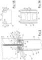
- a portion of a shower enclosure according to the invention indicated generally by the reference numeral 1.
- the shower enclosure 1 in this embodiment of the invention is of the type which is defined by two masonry walls of a structure extending at a right angle to each other, namely, a rear masonry wall 3 and a side masonry wall 5.
- a third side wall of the shower enclosure 1 comprises a panel 7 of toughened glass, which is spaced apart from the side masonry wall 5 and extends parallel thereto, and is secured to the rear masonry wall 3 by an adjustable coupling apparatus also according to the invention and indicated generally by the reference numeral 10.
- a fourth or front wall which is not illustrated of the shower enclosure 1 is formed by a door assembly, which may comprise a hingedly mounted door, a folding door, or a sliding door.
- a door assembly which may comprise a hingedly mounted door, a folding door, or a sliding door.
- Such shower enclosures as the shower enclosure 1 will be well known to those skilled in the art and further description of the shower enclosure should not be required.
- the adjustable coupling apparatus 10 which secures the panel 7 to the rear masonry wall 3
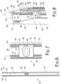
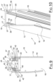
- the adjustable coupling apparatus 10 comprises an elongated mounting member 12 of channel shape construction for mounting on the rear masonry wall 3 by fasteners, for example, screws 14 as will be described below.
- the mounting member 12 comprises an elongated end wall 15, and a pair of spaced apart elongated side walls 16 extending along and from the end wall 15 and defining with the end wall 15 an elongated channel 18 configured to receive the panel 7 therein between the side walls 16.
- Portions 17 of the side walls 16 extend beyond the end wall 15 and terminate in structure abutment faces 19 for abutting the rear masonry wall 3 when the mounting member 12 is secured thereto.
- At least one, and in this embodiment of the invention three longitudinally spaced apart elongated main slots 20 extend through and longitudinally along the end wall 15 for accommodating the screws 14 therethrough for securing the mounting member 12 to the rear masonry wall 3 as will be described below.
- At least one, and in this embodiment of the invention three fastener accommodating elements 22 are located in the channel 18, one fastener accommodating element 22 being provided corresponding to each main slot 20.
- Each fastener accommodating element 22 comprises a secondary slot 24 extending therethrough for accommodating a corresponding one of the screws 14 therethrough.
- Each fastener accommodating element 22 is retained by a retaining means in the channel 18 with the secondary slot 24 thereof extending transversely relative to the corresponding main slot 20.
- each fastener accommodating element 22 also permits each fastener accommodating element 22 to be slideable longitudinally relative to the corresponding main slot 20 in the channel 18 for facilitating longitudinal alignment of the mounting member with a pre-drilled or pre-formed fastener receiving hole 25 in the rear masonry wall 3, while the secondary slot 24 accommodates transverse adjustment of the mounting member 12 relative to the fastener receiving hole 25.
- This thus, permits locating the mounting member 12 on the rear masonry wall 3 in a desired position while at the same time securing the mounting member 12 by screws 14 in the pre-drilled fastener receiving holes 25 which may be slightly off-centre transversely relative to the end wall 15 of the mounting member 12, and may also not be accurately aligned vertically.
- the retaining means for retaining the fastener accommodating element 22 in the channel 18 with the secondary slot 24 extending transversely of the main slot 20, in this embodiment of the invention comprises two pairs of interengageable complementary formations one of the formations of each of the pairs of interengageable complementary formations being formed on the mounting member 12, and the other one of each of the pair of interengageable complementary formations being formed on the fastener accommodating element 22.
- one of the interengageable complementary formations of each of the pairs of the interengageable complementary formations comprises an elongated retaining track 27 extending from the mounting member 12 into the channel 18, and the other one of each pair of the interengageable complementary formations comprising a retaining recess 29 formed in each one of the fastener accommodating elements 22.
- the retaining tracks 27 of the two pairs of interengageable complementary formations extend from the end wall 15 of the mounting member 12 into the channel 18 for engaging the corresponding retaining recesses 29 in each of the fastener accommodating elements 22.
- the retaining tracks 27 extend longitudinally along the length of the end wall 15 along the respective side edges of the main slots 20, and define the side edges of the main slots 20. Each retaining track 27 terminates at its distal edge 30 in an engagement element 32, which extends longitudinally along the distal edge 30 of the corresponding retaining track 27 and transversely therefrom.
- the engagement elements 32 of each of the retaining tracks 27 extend transversely towards each other. However, in some embodiments of the invention it is envisaged that the engagement elements 32 may extend from the retaining tracks 27 transversely away from each other.
- Each retaining recess 29 extends longitudinally through the fastener accommodating element 22 in a longitudinal direction relative to the mounting member 12.
- the retaining recesses 29 extend into the corresponding fastener accommodating elements 22 and terminate therein in engagement recesses 34 which extend longitudinally relative to the retaining recesses 29, and transversely from the retaining recesses 29.
- the engagement recesses 34 extend transversely from the receiving recesses 29 in a direction away from each other.
- the engagement recesses 34 may extend transversely from the retaining recesses 29 towards each other. The direction from which the engagement recesses 34 extend transversely from the retaining recesses 29 will be determined by the direction from which the engagement elements 32 extend transversely from the retaining tracks 27.
- each fastener accommodating element 22 defines with the fastener accommodating element 22 the retaining and engagement recesses 29 and 34.
- the side members 35 terminate in first abutment faces 37 for abutting an inner abutment surface 38 of the end wall 15 when the retaining tracks 27 are engaged in the retaining recesses 29.
- a tapered lead-in 40 is provided on each side member 35 extending inwardly into the corresponding retaining recess 29 from the first abutment face 37 of the side member 35 for accommodating engagement of the retaining tracks 27 in the receiving recesses 29 as each fastener accommodating element 22 is being urged into engagement with the retaining tracks 27.
- Portions 42 of the side members 35 of each fastener accommodating element 22, which partly define the engagement recesses 34 of the retaining recesses 29 are of sufficient resilience to facilitate urging the fastener accommodating elements 22 into engagement with the retaining tracks 27 so that the fastener accommodating element 22 engages the retaining tracks 27 with a snap-fit action.
- An abutment portion 44 extends from each fastener accommodating element 22 between the side members 35 and defines with the side members 35 the retaining recesses 29.
- the abutment portion 44 of each fastener accommodating element 22 is configured to extend through the corresponding main slot 20, and terminates in a second abutment face, namely, a structure abutment face 45, which is configured to abut the rear masonry wall 3 when the fastener accommodating element 22 is tightly secured to the rear masonry wall 3 with the screw 14.
- the spacing S 1 between the structure abutment face 45 of each fastener accommodating element 22 and the first abutment face 37 thereof is just less than the spacing S 2 between the structure abutment faces 19 of the mounting member 12 and the inner face 38 of the end wall 15 of the mounting member 12, so that when each fastener accommodating element 22 is secured by the corresponding screw 14 in the fastener receiving hole 25 with the structure abutment face 45 of the fastener accommodating element 22 tightly abutting the rear masonry wall 3, the first abutment faces 37 of the fastener accommodating element 22 tightly abut the inner face 38 of the end wall 15, to in turn urge the structure abutment faces 19 of the mounting member 12 into tight abutting engagement with the rear masonry wall 3, so that the mounting member 12 is tightly clamped between the fastener accommodating elements 22 and the rear masonry wall 3.
- the spacing S 1 is just sufficiently less than the spacing S 2 , so that the mounting member 12 is tightly clamped between the fastener accommodating elements 22 and the rear masonry wall 3, without distortion of the mounting member 12.
- the spacing S 1 is between 0.5mm and 1mm less than the spacing S 2 .
- the fastener accommodating elements 22 are of injection moulded plastics material, and the plastics material is of sufficient resilience to provide the necessary resilience in the portions 42 of the side members 35 in order to facilitate a snap-fit engagement of the fastener accommodating elements 22 with the retaining tracks 27.
- Material reducing recesses 48 extend into the fastener accommodating elements 22 from the structure abutment face 45 thereof.
- the secondary slot 24 in each fastener accommodating element 22 is countersunk at 49 for accommodating a head 50 of a corresponding screw 14.
- the mounting member 12 is of a plastics material and is formed by extrusion, although it will be appreciated that the mounting member may be of a metal material, for example, aluminium or an aluminium alloy, and typically would be formed by extrusion.
- the retaining tracks 27 and the receiving recesses 29 are sized to provide light frictional sliding movement of the fastener accommodating elements 22 along the retaining tracks 27.
- each fastener accommodating element 22 extends through the corresponding main slot 20
- the main slot 20 is wider than the length of the secondary slot 24 in the corresponding fastener accommodating element 22 in order to accommodate transverse adjustment of the mounting member 12 relative to the fastener receiving hole 25.
- longitudinal adjustment of the mounting member 12 relative to the fastener receiving hole 25 is obtained by sliding the corresponding fastener accommodating element 22 longitudinally along the retaining tracks 27.
- the mounting member 12 will be supplied with the fastener accommodating elements 22 retained in the channel 18 with the retaining tracks 27 engaged in the retaining recesses 29, and in general, one fastener accommodating element 22 will be provided corresponding to each main slot 20, although two or more fastener accommodating elements 22 may be provided for each main slot 20.
- the fastener accommodating elements 22 may be provided separately from the mounting members 12, and in which case, the fastener accommodating elements 22 would be assembled to the mounting members 12 on site by urging the fastener accommodating elements 22 into engagement with the retaining tracks 27, so that the retaining tracks 27 fully engage the retaining recesses 29.
- the mounting member 12 is offered up to the rear masonry wall 3 and is positioned in the desired position on the rear masonry wall 3. If the fastener accommodating elements 22 are not aligned with the pre-drilled fastener receiving holes 25, the fastener accommodating elements 22 are urged along the retaining tracks 27 until the secondary slots 24 in the fastener accommodating elements 22 are aligned with the corresponding pre-drilled fastener receiving holes 25.
- the screws 14 are engaged through the secondary slots 24 into the corresponding pre-drilled fastener receiving holes 25.
- the screws 14 are lightly tightened to lightly tighten the mounting member 12 to the rear masonry wall 3, while still allowing adjustment of the mounting member 12 relative to the rear masonry wall 3.
- Any final adjustment of the mounting member 12 can then be carried out by urging the main mounting member 12 into the desired position both longitudinally and transversely. Transverse adjustment of the mounting member 12 is accommodated by the secondary slots 24 in the fastener accommodating elements 22, and longitudinal adjustment of the mounting member 12 is accommodated by sliding of the fastener accommodating elements 22 in the retaining tracks 27.
- the screws 14 are fully tightened into the pre-drilled fastener receiving holes 25 to thereby secure the fastener accommodating elements 22 with the structure abutment faces 45 tightly abutting the rear masonry wall 3 with the mounting member 12 tightly clamped between the fastener accommodating elements 22 and the rear masonry wall 3.
- the adjustable coupling apparatus 10 for adjusting the position of the mounting member 12 relative to the pre-drilled fastener receiving holes 25 in the rear masonry wall 3
- the pre-drilled fastener receiving holes 25 do not have to be accurately drilled in the rear masonry wall 3, since the mounting member 12 is adjustable longitudinally and transversely relative to the pre-drilled fastener receiving holes 25.
- the advantages of the invention are many.
- the fastener accommodating elements with the secondary slots being configured to extend transversely relative to the longitudinally extending main slots permits two degrees of orthogonal adjustment of the mounting member relative to the structure to which the mounting member is to be secured. This, thus, accommodates and compensates for any inaccuracy in the positions in which the pre-drilled fastener receiving holes have been drilled into the masonry wall or other structure.
- the adjustable coupling apparatus according to the invention provides a relatively simple and inexpensive construction which provides such two degrees of orthogonal adjustment of the mounting member relative to the structure to which it is secured.
- the arrangement of the fastener accommodating elements in the channel of the mounting member facilitates each of both longitudinal and transverse adjustment of the mounting member.
- adjustable coupling apparatus for securing a panel of toughened glass of a shower enclosure to a masonry wall
- the adjustable coupling apparatus may be used for coupling any type of screen or panel to any type of structure, be it a wall, floor, ceiling or other structure
- the structure may be any type of structure, be it a masonry structure, a timber, steel or other structure.
- the adjustable coupling apparatus may be used for coupling a screen which may also be of toughened glass or other suitable panel material to a wall or other structure above a side wall of a bath for partly defining a shower enclosure above and within the bath.
- the adjustable coupling apparatus may be used for coupling any type of screen or panel to any type of structure for any purpose.
- any number of main slots may be provided in the mounting member, and indeed, in some embodiments of the invention it is envisaged that a single elongated mounting slot may be provided extending substantially the length of the mounting member, although, for strength purposes, it is preferably that a plurality of longitudinally spaced apart main slots be provided rather than one continuous elongated slot. It will also be appreciated that more than one fastener accommodating element may be provided for each main slot.
- the mounting member is illustrated as comprising one side wall of curved shape, the side walls of the mounting member may be of any suitable or any desired shape.
- the retaining tracks and the retaining recesses have been described as being of particular shape and cross-section, the retaining tracks and the retaining recesses may be of any suitable desired shape and cross-section.
Landscapes
- Health & Medical Sciences (AREA)
- Public Health (AREA)
- Epidemiology (AREA)
- General Health & Medical Sciences (AREA)
- Connection Of Plates (AREA)
Claims (15)
- Anpassbare Kopplungsvorrichtung zum Koppeln einer Trennwand oder eines Paneels an eine Struktur, die Kopplungsvorrichtung umfassend ein längliches Befestigungselement (12) zum Befestigen an der Struktur (3), wobei das Befestigungselement (12) eine kanalförmige Konstruktion ist, umfassend eine längliche Endwand (15) und ein Paar voneinander beabstandeter länglicher Seitenwände (16), die sich entlang der und von der Endwand (15) erstrecken und mit der Endwand einen länglichen Kanal (18) definieren, der konfiguriert ist die Trennwand oder das Paneel (7) darin zwischen den Seitenwänden (16) aufzunehmen, mindestens eine Hauptöffnung (20), die sich durch die Endwand (15) erstreckt, ein Befestigungsmittelaufnahmeelement (22) mit einer sich durch dieses erstreckenden Sekundäröffnung (24), das in dem Kanal (18) angeordnet ist, und ein Haltemittel (27, 29) zum Halten des Befestigungsmittelaufnahmeelements (22) in dem Kanal (18), wobei die Sekundäröffnung (24) relativ zu der Hauptöffnung (20) angeordnet ist, um ein Befestigungsmittel (14) durch die Sekundäröffnung (24) und die Hauptöffnung (20) an der Struktur (3) aufzunehmen, dadurch gekennzeichnet, dass das Haltemittel (27, 29) dazu konfiguriert ist, zu gestatten, dass das Befestigungsmittelaufnahmeelement (22) longitudinal im Kanal (18) verschiebbar ist, wobei die mindestens eine Hauptöffnung (20) einen länglichen Hauptschlitz (20) umfasst, der sich longitudinal entlang der Endwand (15) des Befestigungselements (12) erstreckt, wobei der Hauptschlitz (20) in longitudinaler Richtung relativ zum Befestigungselement (12) länger ist als dessen Breite in transversaler Richtung relativ zur longitudinalen Richtung des Befestigungselements (12), wobei die Sekundäröffnung (24) einen Sekundärschlitz (24) umfasst, der sich transversal zum Hauptschlitz (20) erstreckt, und der Hauptschlitz (20) in transversaler Richtung eine Breite aufweist, die ausreicht, um einer Anpassung eines Befestigungsmittels (14) im Sekundärschlitz (24) im Wesentlichen über die Länge des Sekundärschlitzes (24) Platz zu bieten.
- Anpassbare Kopplungsvorrichtung wie in Anspruch 1 beansprucht, dadurch gekennzeichnet, dass der Hauptschlitz (20) in transversaler Richtung eine Breite aufweist, die ausreicht, um einer Anpassung eines Befestigungsmittels (14) im Sekundärschlitz (24) entlang der gesamten Länge des Sekundärschlitzes (24) Platz zu bieten.
- Anpassbare Kopplungsvorrichtung wie in Anspruch 1 oder 2 beansprucht, dadurch gekennzeichnet, dass die Breite des Sekundärschlitzes (24) gerade größer ist als die maximale Abmessung eines Schafts eines Befestigungsmittels (14).
- Anpassbare Kopplungsvorrichtung wie in einem der vorhergehenden Ansprüche beansprucht, dadurch gekennzeichnet, dass das Haltemittel (27, 29) mindestens ein Paar ineinander eingreiffähige komplementäre Ausbildungen (27, 29) umfasst, wobei eine der ineinander eingreiffähigen komplementären Ausbildungen (27) an dem Befestigungselement (12) angeordnet ist und die andere der ineinander eingreiffähigen komplementären Ausbildungen (29) an dem Befestigungsmittelaufnahmeelement (22) angeordnet ist.
- Anpassbare Kopplungsvorrichtung wie in Anspruch 4 beansprucht, dadurch gekennzeichnet, dass eine (27) der ineinander eingreiffähigen komplementären Ausbildungen (27, 29) sich von dem Befestigungselement (12) in den Kanal erstreckt, und die andere (29) der ineinander eingreiffähigen komplementären Ausbildungen (27, 29) eine Halteaussparung (29) umfasst, die sich in das Befestigungsmittelaufnahmeelement (22) erstreckt und verschiebbar mit der ineinander eingreiffähigen komplementären Ausbildung (27) in Eingriff bringbar ist, die sich von dem Befestigungselement (12) erstreckt.
- Anpassbare Kopplungsvorrichtung wie in Anspruch 4 oder 5 beansprucht, dadurch gekennzeichnet, dass die ineinander eingreiffähige komplementäre Ausbildung (27), die an dem Befestigungselement (12) angeordnet ist, eine längliche Halteschiene (27) umfasst, die sich longitudinal in dem Kanal (18) erstreckt.
- Anpassbare Kopplungsvorrichtung wie in Anspruch 6 beansprucht, dadurch gekennzeichnet, dass ein Paar von Halteschienen (27) vorgesehen ist, wobei die Halteschienen (27) voneinander beabstandet sind und sich parallel zueinander erstrecken und mit einem entsprechenden Paar der Halteaussparungen (29) in Eingriff bringbar sind, die sich in das Befestigungsmittelaufnahmeelement (22) erstrecken und voneinander beabstandet sind.
- Anpassbare Kopplungsvorrichtung wie in Anspruch 6 oder 7 beansprucht, dadurch gekennzeichnet, dass jede Halteschiene (27) sich mindestens über die Länge des Hauptschlitzes (20) erstreckt.
- Anpassbare Kopplungsvorrichtung wie in einem der Ansprüche 4 bis 8 beansprucht, dadurch gekennzeichnet, dass die ineinander eingreiffähigen komplementären Ausbildungen (28, 29) so konfiguriert sind, dass sie mit einer Einrastbewegung ineinander eingreifen.
- Anpassbare Kopplungsvorrichtung wie in einem der vorhergehenden Ansprüche beansprucht, dadurch gekennzeichnet, dass das Befestigungselement (12) eine Strukturanschlagfläche (19) zum Anschlagen an die Struktur (3) definiert, und das Befestigungsmittelaufnahmeelement (22) eine erste Anschlagfläche (37) zum Anschlagen an eine Innenfläche (38) der Endwand (15) des Befestigungselements (12) definiert und einen Anschlagabschnitt (44) umfasst, der sich von dort durch den Hauptschlitz (20) erstreckt und in einer zweiten Anschlagfläche (45) zum Anschlagen an die Struktur (3) endet, wobei der Abstand (S1) zwischen der ersten Anschlagfläche (37) des Befestigungsmittelaufnahmeelements (22) und der zweiten Anschlagfläche (45) des Anschlagabschnitts (44) des Befestigungsmittelaufnahmeelements (22) gerade geringer ist als der Abstand (S2) zwischen der Innenfläche (38) der Endwand (15) des Befestigungselements (12) und der Strukturanschlagfläche (19) des Befestigungselements (12).
- Anpassbare Kopplungsvorrichtung wie in Anspruch 10 beansprucht, dadurch gekennzeichnet, dass der Abstand (S1) zwischen der ersten Anschlagfläche (37) des Befestigungsmittelaufnahmeelements (22) und der zweiten Anschlagfläche (45) des Anschlagabschnitts (44) des Befestigungsmittelaufnahmeelements (22) weniger als 2 mm kleiner ist als der Abstand (S2) zwischen der Innenfläche (38) der Endwand (15) des Befestigungselements (12) und der Strukturanschlagfläche (19) des Befestigungselements (12), und vorzugsweise weniger als 1 mm kleiner ist als der Abstand (S2) zwischen der Innenfläche (38) der Endwand (15) des Befestigungselements (12) und der Strukturanschlagfläche (19) des Befestigungselements (12), und idealerweise weniger als 0,5 mm kleiner ist als der Abstand (S2) zwischen der Innenfläche (38) der Endwand (15) des Befestigungselements (12) und der Strukturanschlagfläche (19) des Befestigungselements (12).
- Anpassbare Kopplungsvorrichtung wie in einem der vorhergehenden Ansprüche beansprucht, dadurch gekennzeichnet, dass sich eine Vielzahl von sich longitudinal erstreckenden Hauptschlitzen (20) durch die Endwand (15) erstreckt, wobei die Hauptschlitze (20) longitudinal entlang der Endwand (15) voneinander beabstandet sind.
- Struktur, umfassend die in einem der vorhergehenden Ansprüche beanspruchte anpassbare Kopplungsvorrichtung (10), die an der Struktur (3) durch ein Befestigungsmittel (14) befestigt ist, das sich durch den Sekundärschlitz (24) in dem Befestigungsmittelaufnahmeelement (22) und den Hauptschlitz (20) in dem Befestigungselement (12) erstreckt.
- Duschabtrennung, umfassend ein Paneel (7), das eine Wand der Duschabtrennung definiert, und die anpassbare Kopplungsvorrichtung (10), wie in einem der Ansprüche 1 bis 12 beansprucht, die das Paneel (7) an einer Struktur (3) befestigt, die eine angrenzende Wand der Duschabtrennung definiert.
- Verfahren zum Befestigen einer Trennwand oder eines Paneels (7) an einer Struktur (3), das Verfahren umfassend Bereitstellen eines länglichen Befestigungselements (12) mit kanalförmiger Konstruktion, umfassend eine längliche Endwand (15) und ein Paar voneinander beabstandeter länglicher Seitenwände (16), die sich entlang der und von der Endwand (15) erstrecken und mit der Endwand (15) einen länglichen Kanal (18) definieren, der konfiguriert ist die Trennwand oder das Paneel (7) darin zwischen den Seitenwänden (16) aufzunehmen, und mit mindestens einer Hauptöffnung (20), die sich durch die Endwand (15) erstreckt, Anordnen eines Befestigungsmittelaufnahmeelements (22) mit einer sich dadurch erstreckenden Sekundäröffnung (24) in dem Kanal (18) des Befestigungselements (12), Halten des Befestigungsmittelaufnahmeelements (22) in dem Kanal (18) durch ein Haltemittel (27, 29), wobei die Sekundäröffnung (24) relativ zu der Hauptöffnung (20) angeordnet ist, um ein Befestigungsmittel (14) durch die Sekundäröffnung (24) und die Hauptöffnung (20) aufzunehmen, dadurch gekennzeichnet, dass das Haltemittel (27, 29) dazu konfiguriert ist, zu gestatten, dass das Befestigungsmittelaufnahmeelement (22) longitudinal im Kanal (18) verschiebbar ist, wobei die mindestens eine Hauptöffnung (20) als länglicher Hauptschlitz (20) ausgebildet ist, der sich longitudinal entlang der Endwand (15) erstreckt und dessen Länge in longitudinaler Richtung relativ zum Befestigungselement (12) größer ist als dessen Breite in transversaler Richtung relativ zur longitudinalen Richtung des Befestigungselements (12), wobei die Sekundäröffnung (24) als ein Sekundärschlitz (24) ausgebildet ist, der sich transversal zum Hauptschlitz (20) erstreckt, wobei der Hauptschlitz (20) so konfiguriert ist, dass er in transversaler Richtung eine Breite aufweist, die ausreicht, um für die Einstellung eines Befestigungsmittels (14) im Sekundärschlitz (24) im Wesentlichen über die Länge des Sekundärschlitzes (24) Platz zu bieten, und das Verfahren ferner umfasst Anbieten des Befestigungselements (12) für die Struktur (3), wobei der Hauptschlitz (20) grob mit einem Befestigungsmittelaufnahmeloch (25) in der Struktur (3) zur Aufnahme des Befestigungsmittels (14) ausgerichtet ist, Ausrichten des Befestigungsmittelaufnahmeelements (22) in dem Kanal (18) mit dem Sekundärschlitz (24), der mit dem Befestigungsmittelaufnahmeloch (25) in der Struktur (3) ausgerichtet ist, durch Anpassen des Befestigungsmittelaufnahmeelements (22) in Längsrichtung in dem Befestigungselement (12), Einsetzen des Befestigungsmittels (14) durch den Sekundärschlitz (24), durch das Befestigungsmittelaufnahmeelement (22) und durch den Hauptschlitz (20) in das Befestigungsmittelaufnahmeloch (25) in der Struktur (3), leichtes Festziehen des Befestigungsmittels (14) im Befestigungsmittelaufnahmeloch (25), Anpassen der Position des Befestigungselements (12) relativ zur Struktur (3) bis sich das Befestigungselement (12) sowohl in longitudinaler als auch in transversaler Richtung an der gewünschten Stelle relativ zur Struktur (3) befindet, und Festziehen das Befestigungsmittels (14) in dem Befestigungsmittelaufnahmeloch (25), um das Befestigungselement (12) fest an der Struktur (3) zu befestigen.
Applications Claiming Priority (2)
| Application Number | Priority Date | Filing Date | Title |
|---|---|---|---|
| IES20190091 | 2019-06-14 | ||
| PCT/EP2020/066353 WO2020249761A1 (en) | 2019-06-14 | 2020-06-12 | An adjustable coupling apparatus and a method for coupling a screen or a panel to a structure |
Publications (3)
| Publication Number | Publication Date |
|---|---|
| EP3982802A1 EP3982802A1 (de) | 2022-04-20 |
| EP3982802B1 true EP3982802B1 (de) | 2025-05-14 |
| EP3982802C0 EP3982802C0 (de) | 2025-05-14 |
Family
ID=71094363
Family Applications (1)
| Application Number | Title | Priority Date | Filing Date |
|---|---|---|---|
| EP20732873.3A Active EP3982802B1 (de) | 2019-06-14 | 2020-06-12 | Verstellbare kopplungsvorrichtung und verfahren zur kopplung eines bildschirms oder eines paneels an eine struktur |
Country Status (2)
| Country | Link |
|---|---|
| EP (1) | EP3982802B1 (de) |
| WO (1) | WO2020249761A1 (de) |
Family Cites Families (3)
| Publication number | Priority date | Publication date | Assignee | Title |
|---|---|---|---|---|
| DE9001686U1 (de) * | 1990-02-09 | 1990-04-19 | Kermi GmbH, 8350 Plattling | Verstelleinrichtung an Rahmenteilen |
| GB0330066D0 (en) * | 2003-12-27 | 2004-02-04 | Bhd Showers Ltd | Sheet edge support |
| GB201012847D0 (en) * | 2010-07-30 | 2010-09-15 | Lakes Bathrooms Ltd | Hinge for shower door |
-
2020
- 2020-06-12 EP EP20732873.3A patent/EP3982802B1/de active Active
- 2020-06-12 WO PCT/EP2020/066353 patent/WO2020249761A1/en not_active Ceased
Also Published As
| Publication number | Publication date |
|---|---|
| WO2020249761A1 (en) | 2020-12-17 |
| EP3982802A1 (de) | 2022-04-20 |
| EP3982802C0 (de) | 2025-05-14 |
Similar Documents
| Publication | Publication Date | Title |
|---|---|---|
| US5067537A (en) | Fixture for hinge mortise | |
| US4713922A (en) | Frame mounting structure for a housing opening and method therefore | |
| US5845439A (en) | Adjustable door and frame assembly | |
| US20030102417A1 (en) | Reversible garage door track bracket | |
| US4335550A (en) | Prime window unit installation system | |
| US4793109A (en) | Method and apparatus for facing wooden door frames | |
| US5913546A (en) | Stud alignment tool and method of use | |
| US7650670B2 (en) | Hinge attachment system and method | |
| KR101100012B1 (ko) | 도어의 록킹실린더 장착홈 형성장치 | |
| ES2253507T5 (es) | Dispositivo para la sujecion de placas y elemento separador. | |
| EP2093362B1 (de) | Verfahren und Klemmsystem zur Befestigung eines Scharniers oder anderen Beschlags an Profilen für Fenster und Türen | |
| US20210197328A1 (en) | Structural profile | |
| ES2539243T3 (es) | Disposición para el almacenamiento de objetos con elementos de montaje en una pared de construcción en seco y procedimiento de fijación para la misma | |
| EP3982802A1 (de) | Verstellbare kopplungsvorrichtung und verfahren zur kopplung eines bildschirms oder eines paneels an eine struktur | |
| EP1396602A1 (de) | Befestigungsmittel und Verfahren | |
| GB2140066A (en) | Door frame covering | |
| CZ293610B6 (cs) | Upevňovací kování pro podélně drážkované krycí lišty | |
| EP3799235B1 (de) | Trägerbefestigungselement für eine elektrische installationsdose | |
| US20050055952A1 (en) | Adjustable framing stud spacing means | |
| KR200308890Y1 (ko) | 철제거푸집의 간격유지구 | |
| US20250389127A1 (en) | Door sets, and methods of installing door sets | |
| WO2020152664A2 (en) | An adjustable retention device and a frame assembly comprising the adjustable retention device | |
| WO2009070081A1 (en) | A mounting device and a method for making a mounting of a window or a door easy | |
| WO2017106682A2 (en) | Shower enclosure header | |
| US20250223852A1 (en) | Door-hinge jig |
Legal Events
| Date | Code | Title | Description |
|---|---|---|---|
| STAA | Information on the status of an ep patent application or granted ep patent |
Free format text: STATUS: UNKNOWN |
|
| STAA | Information on the status of an ep patent application or granted ep patent |
Free format text: STATUS: THE INTERNATIONAL PUBLICATION HAS BEEN MADE |
|
| PUAI | Public reference made under article 153(3) epc to a published international application that has entered the european phase |
Free format text: ORIGINAL CODE: 0009012 |
|
| STAA | Information on the status of an ep patent application or granted ep patent |
Free format text: STATUS: REQUEST FOR EXAMINATION WAS MADE |
|
| 17P | Request for examination filed |
Effective date: 20211209 |
|
| AK | Designated contracting states |
Kind code of ref document: A1 Designated state(s): AL AT BE BG CH CY CZ DE DK EE ES FI FR GB GR HR HU IE IS IT LI LT LU LV MC MK MT NL NO PL PT RO RS SE SI SK SM TR |
|
| DAV | Request for validation of the european patent (deleted) | ||
| DAX | Request for extension of the european patent (deleted) | ||
| GRAP | Despatch of communication of intention to grant a patent |
Free format text: ORIGINAL CODE: EPIDOSNIGR1 |
|
| STAA | Information on the status of an ep patent application or granted ep patent |
Free format text: STATUS: GRANT OF PATENT IS INTENDED |
|
| INTG | Intention to grant announced |
Effective date: 20241213 |
|
| GRAS | Grant fee paid |
Free format text: ORIGINAL CODE: EPIDOSNIGR3 |
|
| GRAA | (expected) grant |
Free format text: ORIGINAL CODE: 0009210 |
|
| STAA | Information on the status of an ep patent application or granted ep patent |
Free format text: STATUS: THE PATENT HAS BEEN GRANTED |
|
| AK | Designated contracting states |
Kind code of ref document: B1 Designated state(s): AL AT BE BG CH CY CZ DE DK EE ES FI FR GB GR HR HU IE IS IT LI LT LU LV MC MK MT NL NO PL PT RO RS SE SI SK SM TR |
|
| REG | Reference to a national code |
Ref country code: GB Ref legal event code: FG4D |
|
| REG | Reference to a national code |
Ref country code: CH Ref legal event code: EP |
|
| REG | Reference to a national code |
Ref country code: IE Ref legal event code: FG4D |
|
| REG | Reference to a national code |
Ref country code: DE Ref legal event code: R096 Ref document number: 602020051251 Country of ref document: DE |
|
| U01 | Request for unitary effect filed |
Effective date: 20250520 |
|
| U07 | Unitary effect registered |
Designated state(s): AT BE BG DE DK EE FI FR IT LT LU LV MT NL PT RO SE SI Effective date: 20250605 |
|
| U20 | Renewal fee for the european patent with unitary effect paid |
Year of fee payment: 6 Effective date: 20250613 |
|
| PG25 | Lapsed in a contracting state [announced via postgrant information from national office to epo] |
Ref country code: ES Free format text: LAPSE BECAUSE OF FAILURE TO SUBMIT A TRANSLATION OF THE DESCRIPTION OR TO PAY THE FEE WITHIN THE PRESCRIBED TIME-LIMIT Effective date: 20250514 |
|
| PG25 | Lapsed in a contracting state [announced via postgrant information from national office to epo] |
Ref country code: NO Free format text: LAPSE BECAUSE OF FAILURE TO SUBMIT A TRANSLATION OF THE DESCRIPTION OR TO PAY THE FEE WITHIN THE PRESCRIBED TIME-LIMIT Effective date: 20250814 Ref country code: GR Free format text: LAPSE BECAUSE OF FAILURE TO SUBMIT A TRANSLATION OF THE DESCRIPTION OR TO PAY THE FEE WITHIN THE PRESCRIBED TIME-LIMIT Effective date: 20250815 |
|
| PG25 | Lapsed in a contracting state [announced via postgrant information from national office to epo] |
Ref country code: PL Free format text: LAPSE BECAUSE OF FAILURE TO SUBMIT A TRANSLATION OF THE DESCRIPTION OR TO PAY THE FEE WITHIN THE PRESCRIBED TIME-LIMIT Effective date: 20250514 |
|
| PG25 | Lapsed in a contracting state [announced via postgrant information from national office to epo] |
Ref country code: HR Free format text: LAPSE BECAUSE OF FAILURE TO SUBMIT A TRANSLATION OF THE DESCRIPTION OR TO PAY THE FEE WITHIN THE PRESCRIBED TIME-LIMIT Effective date: 20250514 |
|
| PG25 | Lapsed in a contracting state [announced via postgrant information from national office to epo] |
Ref country code: RS Free format text: LAPSE BECAUSE OF FAILURE TO SUBMIT A TRANSLATION OF THE DESCRIPTION OR TO PAY THE FEE WITHIN THE PRESCRIBED TIME-LIMIT Effective date: 20250814 |
|
| PG25 | Lapsed in a contracting state [announced via postgrant information from national office to epo] |
Ref country code: IS Free format text: LAPSE BECAUSE OF FAILURE TO SUBMIT A TRANSLATION OF THE DESCRIPTION OR TO PAY THE FEE WITHIN THE PRESCRIBED TIME-LIMIT Effective date: 20250914 |
|
| PG25 | Lapsed in a contracting state [announced via postgrant information from national office to epo] |
Ref country code: SM Free format text: LAPSE BECAUSE OF FAILURE TO SUBMIT A TRANSLATION OF THE DESCRIPTION OR TO PAY THE FEE WITHIN THE PRESCRIBED TIME-LIMIT Effective date: 20250514 |
|
| PG25 | Lapsed in a contracting state [announced via postgrant information from national office to epo] |
Ref country code: CZ Free format text: LAPSE BECAUSE OF FAILURE TO SUBMIT A TRANSLATION OF THE DESCRIPTION OR TO PAY THE FEE WITHIN THE PRESCRIBED TIME-LIMIT Effective date: 20250514 |
|
| PG25 | Lapsed in a contracting state [announced via postgrant information from national office to epo] |
Ref country code: SK Free format text: LAPSE BECAUSE OF FAILURE TO SUBMIT A TRANSLATION OF THE DESCRIPTION OR TO PAY THE FEE WITHIN THE PRESCRIBED TIME-LIMIT Effective date: 20250514 |
|
| REG | Reference to a national code |
Ref country code: CH Ref legal event code: H13 Free format text: ST27 STATUS EVENT CODE: U-0-0-H10-H13 (AS PROVIDED BY THE NATIONAL OFFICE) Effective date: 20260127 |
|
| PG25 | Lapsed in a contracting state [announced via postgrant information from national office to epo] |
Ref country code: MC Free format text: LAPSE BECAUSE OF FAILURE TO SUBMIT A TRANSLATION OF THE DESCRIPTION OR TO PAY THE FEE WITHIN THE PRESCRIBED TIME-LIMIT Effective date: 20250514 |
|
| PLBE | No opposition filed within time limit |
Free format text: ORIGINAL CODE: 0009261 |
|
| STAA | Information on the status of an ep patent application or granted ep patent |
Free format text: STATUS: NO OPPOSITION FILED WITHIN TIME LIMIT |
|
| REG | Reference to a national code |
Ref country code: CH Ref legal event code: L10 Free format text: ST27 STATUS EVENT CODE: U-0-0-L10-L00 (AS PROVIDED BY THE NATIONAL OFFICE) Effective date: 20260325 |
|
| 26N | No opposition filed |
Effective date: 20260217 |
|
| PG25 | Lapsed in a contracting state [announced via postgrant information from national office to epo] |
Ref country code: CH Free format text: LAPSE BECAUSE OF NON-PAYMENT OF DUE FEES Effective date: 20250630 |
|
| U20 | Renewal fee for the european patent with unitary effect paid |
Year of fee payment: 7 Effective date: 20260427 |
|
| PGFP | Annual fee paid to national office [announced via postgrant information from national office to epo] |
Ref country code: GB Payment date: 20260427 Year of fee payment: 7 |
|
| PGFP | Annual fee paid to national office [announced via postgrant information from national office to epo] |
Ref country code: IE Payment date: 20260427 Year of fee payment: 7 |
|
| PG25 | Lapsed in a contracting state [announced via postgrant information from national office to epo] |
Ref country code: CY Free format text: LAPSE BECAUSE OF FAILURE TO SUBMIT A TRANSLATION OF THE DESCRIPTION OR TO PAY THE FEE WITHIN THE PRESCRIBED TIME-LIMIT Effective date: 20250514 |