EP3983149B1 - Procédé de fabrication d'une forme de départ d'élément de visserie ainsi que d'un élément de visserie, et forme de départ d'élément de visserie ainsi qu'élément de visserie - Google Patents
Procédé de fabrication d'une forme de départ d'élément de visserie ainsi que d'un élément de visserie, et forme de départ d'élément de visserie ainsi qu'élément de visserie Download PDFInfo
- Publication number
- EP3983149B1 EP3983149B1 EP20724750.3A EP20724750A EP3983149B1 EP 3983149 B1 EP3983149 B1 EP 3983149B1 EP 20724750 A EP20724750 A EP 20724750A EP 3983149 B1 EP3983149 B1 EP 3983149B1
- Authority
- EP
- European Patent Office
- Prior art keywords
- shaft
- section
- head
- screw
- blind hole
- Prior art date
- Legal status (The legal status is an assumption and is not a legal conclusion. Google has not performed a legal analysis and makes no representation as to the accuracy of the status listed.)
- Active
Links
Images



Classifications
-
- B—PERFORMING OPERATIONS; TRANSPORTING
- B21—MECHANICAL METAL-WORKING WITHOUT ESSENTIALLY REMOVING MATERIAL; PUNCHING METAL
- B21H—MAKING PARTICULAR METAL OBJECTS BY ROLLING, e.g. SCREWS, WHEELS, RINGS, BARRELS, BALLS
- B21H3/00—Making helical bodies or bodies having parts of helical shape
- B21H3/02—Making helical bodies or bodies having parts of helical shape external screw-threads ; Making dies for thread rolling
-
- B—PERFORMING OPERATIONS; TRANSPORTING
- B21—MECHANICAL METAL-WORKING WITHOUT ESSENTIALLY REMOVING MATERIAL; PUNCHING METAL
- B21J—FORGING; HAMMERING; PRESSING METAL; RIVETING; FORGE FURNACES
- B21J5/00—Methods for forging, hammering, or pressing; Special equipment or accessories therefor
- B21J5/06—Methods for forging, hammering, or pressing; Special equipment or accessories therefor for performing particular operations
- B21J5/12—Forming profiles on internal or external surfaces
-
- B—PERFORMING OPERATIONS; TRANSPORTING
- B21—MECHANICAL METAL-WORKING WITHOUT ESSENTIALLY REMOVING MATERIAL; PUNCHING METAL
- B21K—MAKING FORGED OR PRESSED METAL PRODUCTS, e.g. HORSE-SHOES, RIVETS, BOLTS OR WHEELS
- B21K1/00—Making machine elements
- B21K1/44—Making machine elements bolts, studs, or the like
- B21K1/46—Making machine elements bolts, studs, or the like with heads
- B21K1/463—Making machine elements bolts, studs, or the like with heads with recessed heads
-
- B—PERFORMING OPERATIONS; TRANSPORTING
- B21—MECHANICAL METAL-WORKING WITHOUT ESSENTIALLY REMOVING MATERIAL; PUNCHING METAL
- B21K—MAKING FORGED OR PRESSED METAL PRODUCTS, e.g. HORSE-SHOES, RIVETS, BOLTS OR WHEELS
- B21K1/00—Making machine elements
- B21K1/56—Making machine elements screw-threaded elements
-
- B—PERFORMING OPERATIONS; TRANSPORTING
- B21—MECHANICAL METAL-WORKING WITHOUT ESSENTIALLY REMOVING MATERIAL; PUNCHING METAL
- B21K—MAKING FORGED OR PRESSED METAL PRODUCTS, e.g. HORSE-SHOES, RIVETS, BOLTS OR WHEELS
- B21K1/00—Making machine elements
- B21K1/64—Making machine elements nuts
-
- F—MECHANICAL ENGINEERING; LIGHTING; HEATING; WEAPONS; BLASTING
- F01—MACHINES OR ENGINES IN GENERAL; ENGINE PLANTS IN GENERAL; STEAM ENGINES
- F01M—LUBRICATING OF MACHINES OR ENGINES IN GENERAL; LUBRICATING INTERNAL COMBUSTION ENGINES; CRANKCASE VENTILATING
- F01M11/00—Component parts, details or accessories, not provided for in, or of interest apart from, groups F01M1/00 - F01M9/00
- F01M11/04—Filling or draining lubricant of or from machines or engines
- F01M11/0408—Sump drainage devices, e.g. valves, plugs
-
- F—MECHANICAL ENGINEERING; LIGHTING; HEATING; WEAPONS; BLASTING
- F16—ENGINEERING ELEMENTS AND UNITS; GENERAL MEASURES FOR PRODUCING AND MAINTAINING EFFECTIVE FUNCTIONING OF MACHINES OR INSTALLATIONS; THERMAL INSULATION IN GENERAL
- F16B—DEVICES FOR FASTENING OR SECURING CONSTRUCTIONAL ELEMENTS OR MACHINE PARTS TOGETHER, e.g. NAILS, BOLTS, CIRCLIPS, CLAMPS, CLIPS OR WEDGES; JOINTS OR JOINTING
- F16B33/00—Features common to bolt and nut
- F16B33/004—Sealing; Insulation
-
- F—MECHANICAL ENGINEERING; LIGHTING; HEATING; WEAPONS; BLASTING
- F16—ENGINEERING ELEMENTS AND UNITS; GENERAL MEASURES FOR PRODUCING AND MAINTAINING EFFECTIVE FUNCTIONING OF MACHINES OR INSTALLATIONS; THERMAL INSULATION IN GENERAL
- F16B—DEVICES FOR FASTENING OR SECURING CONSTRUCTIONAL ELEMENTS OR MACHINE PARTS TOGETHER, e.g. NAILS, BOLTS, CIRCLIPS, CLAMPS, CLIPS OR WEDGES; JOINTS OR JOINTING
- F16B35/00—Screw-bolts; Stay-bolts; Screw-threaded studs; Screws; Set screws
-
- F—MECHANICAL ENGINEERING; LIGHTING; HEATING; WEAPONS; BLASTING
- F16—ENGINEERING ELEMENTS AND UNITS; GENERAL MEASURES FOR PRODUCING AND MAINTAINING EFFECTIVE FUNCTIONING OF MACHINES OR INSTALLATIONS; THERMAL INSULATION IN GENERAL
- F16B—DEVICES FOR FASTENING OR SECURING CONSTRUCTIONAL ELEMENTS OR MACHINE PARTS TOGETHER, e.g. NAILS, BOLTS, CIRCLIPS, CLAMPS, CLIPS OR WEDGES; JOINTS OR JOINTING
- F16B37/00—Nuts or like thread-engaging members
-
- F—MECHANICAL ENGINEERING; LIGHTING; HEATING; WEAPONS; BLASTING
- F16—ENGINEERING ELEMENTS AND UNITS; GENERAL MEASURES FOR PRODUCING AND MAINTAINING EFFECTIVE FUNCTIONING OF MACHINES OR INSTALLATIONS; THERMAL INSULATION IN GENERAL
- F16B—DEVICES FOR FASTENING OR SECURING CONSTRUCTIONAL ELEMENTS OR MACHINE PARTS TOGETHER, e.g. NAILS, BOLTS, CIRCLIPS, CLAMPS, CLIPS OR WEDGES; JOINTS OR JOINTING
- F16B33/00—Features common to bolt and nut
- F16B33/02—Shape of thread; Special thread-forms
-
- F—MECHANICAL ENGINEERING; LIGHTING; HEATING; WEAPONS; BLASTING
- F16—ENGINEERING ELEMENTS AND UNITS; GENERAL MEASURES FOR PRODUCING AND MAINTAINING EFFECTIVE FUNCTIONING OF MACHINES OR INSTALLATIONS; THERMAL INSULATION IN GENERAL
- F16L—PIPES; JOINTS OR FITTINGS FOR PIPES; SUPPORTS FOR PIPES, CABLES OR PROTECTIVE TUBING; MEANS FOR THERMAL INSULATION IN GENERAL
- F16L55/00—Devices or appurtenances for use in, or in connection with, pipes or pipe systems
- F16L55/10—Means for stopping flow in pipes or hoses
- F16L55/11—Plugs
- F16L55/1108—Plugs fixed by screwing or by means of a screw-threaded ring
Definitions
- the invention relates to a method for producing a screw element blank and for producing a screw element according to the preamble of claim 1. Furthermore, the present invention relates to a screw element blank according to claim 17 and a screw element according to claim 24.
- screws and nuts are used, among other things, to connect components to one another and to close openings.
- An inventive concept is described here which can be used both for screws, in particular closure or sealing screws, and for nuts, in particular fastening nuts with/for defined friction values.
- sealing screws or screw plugs are known from the prior art.
- the known sealing screws or screw plugs are preferably, but by no means exclusively, used as oil drain plugs, which are used to seal an internal thread opening in a receiving body, in particular to seal a liquid line or to seal a liquid vessel, preferably in an oil line or in an oil container, wherein the oil line or the oil container is preferably assigned to a gearbox or gearbox housing of an internal combustion engine.
- the screw plugs or sealing screws are provided with an external thread, in particular with a cylindrical shaft with an external thread located there, with which a Screwing with an internal thread of an internal thread opening of the said receiving body.
- sealing screws In the case of the known locking screws or sealing screws, which will be referred to as sealing screws throughout the following, it has proven to be particularly advantageous with regard to the sealing effect between the sealing screw and the receiving body if the sealing screw has an undercut or undercut at the transition between the shaft having the external thread and a head adjacent to the shaft, which achieves or enables in a particularly advantageous manner that the head or screw head, in particular a sealing surface of the screw head facing the shaft, comes to rest sealingly against a corresponding counter surface of the receiving opening or the receiving body.
- sealing screws and methods for producing sealing screw blanks and sealing screws are known, in which not only but especially the undercut discussed above is produced at the transition between the cylindrical shaft of the screw and the screw head by means of cold extrusion.
- sealing screw blanks and sealing screws using cold extrusion are, on the one hand, the optimized or loss-free use of material and, on the other hand, the saving of additional process steps, in particular process steps for clamping, turning and machining screws or screw blanks.
- the resulting sealing screws and sealing screw blanks are characterized accordingly.
- the WO 2004/054739 forms the basis for the preamble of claims 1 and 17.
- the WO 2019/105556 A1 discloses a multi-part sealing screw comprising a screw element with a pressing section, as well as a separate cover element (70).
- the cover element is configured to be connected to the screw element and to press the pressing section with sealing element against a lateral wall of a through hole to be sealed.
- the EN 10 2014 118 342 A1 shows a method for producing a screw unit comprising a screw element with a shaft and a head projecting radially beyond the shaft, as well as a central through-opening penetrated by a disc, wherein a radially projecting rear grip element is present on the shaft, with the following steps: a) a disc blank is provided with a through-opening whose diameter is larger than the diameter of the rear grip element, b) the shaft already provided with a fixing element is inserted into the through-opening so far that a first shaft section extending away from the head penetrates through it, c) by a radially inwardly directed plastic deformation of at least part of the edge region of the disc blank, the through-opening is reduced in size, forming a radial overlap between the rear grip element and the edge region of the disc.
- sealing screws are increasingly desired or required which have an undercut between the shaft end and the screw head which has a positive effect on the tightness, but at the same time should have a flat surface on the end of the screw shaft facing away from the screw head, in particular a flat front surface or even an extension extending from a front surface away from the screw head, the production of such sealing screws and their blanks by means of cold extrusion was not possible.
- screw elements formed as screw nut blanks and screw nuts as well as the corresponding processes
- the state of the art for example from EN 10 2011 107 236 A1
- Nuts or screw elements which enable a particularly space-saving fastening of a component screwed into a screw opening of the nut, for example a steering element, particularly preferably an upper wishbone of a motor vehicle on a corresponding fastening element.
- the screw elements in the form of screw nuts can also be manufactured using cold extrusion.
- the advantage of the processes for their manufacture using cold extrusion is also the optimized or loss-free use of material and on the other hand the saving of additional process steps, in particular process steps for clamping, turning and machining nuts or screw nuts.
- the resulting sealing screws and sealing screw blanks are also characterized accordingly.
- an undercut or undercut in a transition area between a head or nut head and a shaft or nut shaft has also proven to be advantageous, as the diameter of the shaft can then be selected so that it is slightly larger than the inner diameter of the washer and the outer diameter of the undercut or undercut is slightly smaller than the inner diameter of the washer, so that in the area of the Undercut the washer can be secured or positioned in a loss-proof manner.
- the object of the present invention is to provide screw elements and screw element blanks as well as methods for their production, in which the sealing screws on the one hand have a flat surface or end face facing away from the head or provided with an extension, at the same time have the undercut between the shaft and the head which improves the sealing effect or the securing effect and can be produced by means of cold bulk forming, in particular cold extrusion, preferably without machining steps.
- a method for producing a screw element or a screw element blank comprising a method step in which a blank is produced with a cylindrical shaft formed on a head and wherein in the blank, from an upper side of the head facing away from the shaft, in particular in further method steps, a blind hole is formed which extends in the direction of the shaft and which has at least a first section, in particular with a polygonal cross-section, preferably for receiving a screwing tool or a round cross-section as a preliminary stage of a screw-in opening, the above-mentioned object is achieved in that, in a subsequent method step, the blind hole already existing on the head side is deepened to form at least a second section adjacent to the first section, wherein the second section forms a cross-section which is preferably at least partially constant, in particular smaller or constant than the first cross-section, wherein in the subsequent method step the shaft is widened in sections to form an undercut at the transition between the shaft and the head by at least indirect material displacement from at least the second section of the blind hole
- the present invention is therefore based on the idea that, precisely by overcoming the assumptions or prejudices outlined above with regard to the limitations of cold extrusion, an expansion together with the formation of a corresponding undercut between the shaft, which is at least partially expanded, and the head is also made possible by carrying out a rear-side deformation, i.e. a deformation starting from the head, in particular material displacement, and at the same time the screw element or the screw element blank after the subsequent process step nevertheless remains removable from a tool that holds the blank, in particular in the axial direction of the blank.
- a rear-side deformation i.e. a deformation starting from the head, in particular material displacement
- the screw element or screw element blank continues to have the undercut at the transition between the shaft and the head, which has a particularly positive effect on the application.
- the shaft is widened at least in an area opposite the head.
- a thread to be formed, in particular rolled, into the widening or in the area of the widening in this area, namely opposite the head, whereas in the less or not widened area of the shaft, namely in an area of the shaft that faces the head, the thread is not introduced and instead the undercut is formed to improve the tightness between the sealing screw and the receiving body.
- the formation of the widening in the area facing away from the head or opposite the head is also particularly advantageous. of the shaft is an expression of inventive achievement and inventive deviation from known or supposedly known restrictions of cold extrusion.
- the tool which receives the screw or the screw blank for carrying out the subsequent process step is designed as a one-piece tool, at least in the circumferential direction, so that, for example, the radial opening of two or more tool parts is not possible or is not provided for in order to remove or To ensure removal of the screw blank or screw after the subsequent process step.
- a part of the expanded section rests against a radial deformation tool or tool part, whereas the part of the shaft forming the undercut has an increasing distance from the radial deformation tool or tool part in the axial direction of the head.
- this embodiment deviates from the previous principles of cold extrusion, since the said tool or the tool part, which at least partially or partially accommodates the shaft for the subsequent process step after completion of the subsequent process step, does not rest completely on the shaft or over the full axial extent of the shaft, or vice versa, the shaft rests on the tool or the tool part, as has previously been the case with cold extrusion processes, but rather that only in an axial end region, in particular in an axial end region of the shaft facing away from the head, the indirect material displacement caused by the formation and/or deepening of the head-side blind hole leads to a maximum expansion and thus to a contact between the expanded cylindrical shaft and the tool, whereas with increasing distance from the end region of the shaft, in particular with increasing distance from the end region of the shaft opposite the head, an increasing distance between the tool or tool part, in particular after completion of the subsequent process step, remains, so that the undercut is formed between the shaft and the head.
- an annular sealing surface is formed on an underside of the head facing the shaft for contact with a support surface of a receiving body, forming a coaxial annular groove which is delimited radially outwards by a circumferential annular wall.
- the sealing behavior of the sealing screw is further advantageously influenced or increased. It can preferably be provided that the corresponding annular sealing surface is formed before the subsequent process step and is retained in the subsequent process step. Alternatively, however, it can also be provided that the sealing surface is only formed or shaped in the subsequent process step, together with the formation or depression of the blind hole.
- a washer is arranged in the area of the undercut, wherein the washer is deformed in such a way that after deformation the inner diameter is slightly larger than the outer diameter of the undercut and also the inner diameter of the washer is smaller than the outer diameter of the expanded section of the shaft.
- a maximum expansion of 2% to 9%, in particular 5% to 7% is produced in the subsequent process step compared to the shaft diameter, in particular compared to a shaft diameter that is not deformed in the subsequent process step.
- a corresponding expansion of 2% to 9%, in particular 5% to 7% has proven to be advantageous because, on the one hand, this allows a thread to be introduced, in particular cut, in the area of the expansion and, at the same time, a correspondingly complete, cleanly formed undercut is achieved.
- the blind hole is formed in such a way that a base, in particular of the second section of the blind hole, starting from the top of the head, extends up to 80%, preferably up to 75%, particularly preferably up to 70%, further preferably up to 45% of the total height of the screw element.
- the total height of the screw element should extend between a front side or a front face of the shaft, in particular without taking into account any extensions of the shaft, up to a top of the head.
- the formation of the blind hole, in particular of the second section of the blind hole, to a depth of up to 80% of the total height particularly advantageously allows at least indirect material displacement into a section of the shaft that reaches or extends to the front side or front face of the shaft. This ensures that the widening already assumes its maximum extent immediately or shortly behind the front side or front face and thus a thread can already be introduced in this area. This provides a sufficient section in the axial direction for providing or inserting the thread of the sealing screw.
- a penetration depth of the second section of 40% to 45% may already be sufficient, since the expansion for securing the washer does not need to be as strong.
- the first section of the blind hole is formed such that a bottom of the first section of the blind hole, starting from the top of the head, extends up to 70%, preferably up to 65%, particularly preferably up to 40% of the total height of the screw element.
- the distance between a front side or front face of the shaft (not taking the extensions into account) and the top of the head should again be taken into account.
- Such a design of the first section of the blind hole means that, if this is provided for, a tool can be held securely in the first section of the blind hole.
- this also makes it possible to manufacture the screw element using relatively little material. This in turn can advantageously reduce the manufacturing costs of the screw element and the costs of carrying out the process.
- the formation of the first section of the blind hole is carried out in two or more sub-steps, wherein preferably 70%, more preferably 80% of the total depth of the blind hole, i.e. the first section of the blind hole, is produced in a first sub-step.
- Another particularly preferred embodiment of the method, in particular for producing a sealing screw can also provide that, as part of the subsequent method step, the second section of the blind hole is formed in such a way that a bottom of the, in particular second section, of the blind hole is formed in an area of maximum radial expansion in the axial direction.
- This also means that with the formation of the blind hole a kind of reversal of the flow direction of the material during cold extrusion is achieved, at least when considering the material displacement indirectly.
- the second section of the blind hole is designed in such a way that a bottom of the blind hole is formed in the axial direction in the head of the screw element or the screw element blank.
- the relatively low penetration depth of the blind hole, in particular of the second section of the blind hole has various reasons for the production of a screw element in the form of a nut or a screw nut.
- only a comparatively small widening of the shaft is necessary for the captive or loss-proof fastening of a washer in the area of the undercut or undercut of the screw element.
- the shaft of a screw element in the form of a nut or screw nut is usually significantly shorter than the shaft of a sealing screw or a comparable screw element, so that forming the second section of the blind hole in the area of the head is sufficient to achieve a radial widening in the relatively short shaft caused by at least indirect material displacement, including the formation of an undercut or undercut.
- the shaft in particular the shaft surface, is provided with an external thread by rolling, wherein the thread is formed relative to the widening and the undercut such that the thread runs out completely in the area of the undercut.
- the material of the screw element blank is punched out or cut out between the bottom of the second section and an end face of the shaft facing away from the head, in particular while retaining the undercut, as part of a hole-producing step.
- a hole with a diameter is punched or punched out which corresponds to the diameter of the blind hole, in particular in the first and second sections.
- first section of the blind hole and the second section of the blind hole have an identical diameter and are in particular round or circular.
- the hole creation or the hole creation step can also be designed such that a circular hole is punched or punched out between the bottom of the second section of the blind hole and the end face of the shaft facing away from the head. This makes it particularly advantageous to provide a screw-in opening for the screw element designed as a nut or screw nut.
- Adapting to the diameter of the blind hole has the advantage that relatively little material is punched or punched out of the blank or screw element blank, thus resulting in less material waste.
- a further advantageous embodiment of the method which preferably relates to the production of a screw element or screw element blank in the form of a nut or screw nut, can also provide that an internal thread is produced in the hole produced in the hole production step, in particular by means of machining, which preferably extends from the head to an end face of the shaft facing away from the head.
- the screw element as a screw, in particular a sealing screw
- the outer surface of the shaft in particular also the widened area of the shaft, which forms the undercut or undercut with increasing transition to the head, is not further machined.
- This area of a corresponding screw nut or nut can be inserted into a corresponding recess of a fastening element and there ensure, for example, the centering of the screw nut.
- a relatively long internal thread is provided and thus a correspondingly good fastening effect is achieved, although, particularly when a recess or depression is provided in the fastening element to accommodate the shaft, the screw nut, when fastened to the fastening element, only protrudes slightly beyond the fastening element, namely by the height of the head.
- connection or fastening in which a washer is also arranged at the transition between the shaft and head in a captive or loss-proof manner, also makes it possible to achieve a connection or fastening in which the friction values can be predicted or determined particularly precisely.
- the height of the nut protruding above the fastening element is slightly increased by the height of the washer.
- a further particularly preferred embodiment of the method which also preferably aims at the formation of a screw element designed as a nut or screw nut, can also provide that in a further method step, preferably after the formation of the first section of the blind hole in the head of the screw element blank, an external tool engagement, in particular an external multi-tooth, is formed in the region of the head, which preferably extends over the entire height of the head, at least after a subsequent deburring process.
- the formation of the tool attack in particular from the external tool attack in the area of the head of the screw element blank can preferably be produced as part of cold forming, in particular as part of cold extrusion, wherein at least parts of the material of the head are displaced to form a burr running around the head in the circumferential direction.
- the burr thus created can be deburred as part of a further process step.
- the deburring can be carried out in the same process step as the formation of the second section of the blind hole and thus together with the formation of the undercut or undercut.
- a screw element blank which has a head and a cylindrical shaft formed on the screw head, wherein a blind hole extends from the head in the direction of the shaft, which has at least a first section, in particular with a polygonal cross-section, preferably for receiving a screwing tool or a round cross-section as a preliminary stage of a screw-in opening, and has an undercut at the transition between the screw head and the shaft, in that the blind hole has a second section adjacent to the first section, wherein the second section preferably has a cross-section which is at least partially the same, in particular smaller or the same size as the first cross-section, wherein the undercut at the transition between the shaft and the head is formed by a, in particular by at least indirect material displacement from at least the second section of the blind hole, sectionally formed widening of the shaft.
- screw element blanks are produced in accordance with the invention using the cold extrusion process, which on the one hand are subject to no or hardly any restrictions with regard to the design of the front face or front side of the shaft and which, with the undercut between the shaft and the head, also produce a particularly high sealing effect or an advantageous securing effect to prevent the loss of a washer.
- the shaft has an expansion at least in an area opposite the screw head.
- the expansion can thus form the basis for the formation of the undercut without machining the shaft and/or head.
- the expansion is particularly advantageously not achieved by a material displacement or material deformation in the area of the front face or front side of the shaft, but rather by the material displacement and/or material deformation in the area of the second section of the blind hole.
- a flat front surface of the shaft facing away from the screw head or a front surface of the shaft provided with an extension extending axially away from the front surface is formed.
- a preferred embodiment of the screw element blank provides that a maximum expansion of the shaft, in particular a maximum expansion of the shaft relative to of a diameter not expanded as part of the subsequent process step is 2% to 9%, in particular 5% to 7%. It can preferably be provided that the non-expanded or original shaft diameter is measured or determined at the transition between the screw head and the shaft. This advantageously ensures that the expansion is large enough to form the undercut, even if a thread is introduced, in particular rolled or rolled in, in the expanded area of the shaft with a certain tolerance. With a relatively small expansion, for example in the range of 2% to 3%, the locking effect for a washer can advantageously be achieved for the formation of a screw nut through the expansion and the resulting undercut.
- a base in particular of the second section of the blind hole, extends from the top of the head up to 80%, preferably up to 75%, particularly preferably up to 70%, further preferably up to 45% of the total height of the blank or the finished screw element.
- a base in particular of the second section of the blind hole
- the design of the base of the second section of the blind hole also allows sufficient widening of the shaft at the end opposite the head and a corresponding tapering of the shaft in the direction of the transition between shaft and head, in particular to form the undercut.
- a base of the second section of the blind hole runs or is arranged in the axial direction in an area of maximum radial expansion.
- This not only causes the shaft to expand radially in the corresponding section in a particularly advantageous manner, at least through indirect material displacement, but also simultaneously causes a uniform flank to form as a transition between an expanded and a non-expanded area of the diameter of the shaft, so that on the one hand it is possible for an introduced or rolled or rolled-in thread to run out in this area, and on the other hand a transition is created between the thread area and the undercut area or the undercut.
- the blind hole has a third section adjacent to the second section, which is formed concentrically to the first and/or second section of the blind hole and preferably forms a conical segment which tapers in the direction of the shaft and in particular opens into a flat bottom of the blind hole running parallel to the top.
- the third section of the blind hole can preferably be formed together with the second section of the blind hole in the subsequent process step.
- the third section of the blind hole leads to the optimization or minimization of the material requirement.
- the third section of the blind hole enables a particularly precise and uniform formation of a transition between a widened section of the shaft and a non-widened section of the shaft or a section of the shaft forming an undercut.
- the above-mentioned object is achieved in that the screw element, in particular the sealing screw, is produced from a screw element blank of the type described above.
- the screw element in particular the sealing screw
- a screw element blank of the type described above is produced from a screw element blank of the type described above.
- the shaft of the screw element in particular the shaft surface, has a thread, in particular an external thread, wherein the thread is designed relative to the widening and the undercut of the shaft such that the thread runs out completely in the area of the undercut.
- the screw element in particular a nut or screw nut
- the screw element is manufactured from a screw element blank described above.
- an undercut or undercut is also provided between the shaft and the head or in an area of the shaft adjacent to the head. is formed without its formation requiring a significant deformation of the end of the shaft facing away from the head or of the front side of the shaft facing away from the head.
- a screw-in opening is included, which is formed by a recess in the shaft that widens the blind hole of the screw element blank to form an axially continuous opening.
- the screw-in opening is formed after the undercut or undercut has been formed, in particular punched out or drilled out.
- the screw-in hole or the screw-in opening, as well as the blind hole is particularly preferably drilled out from the side of the head. This means that the screw-in opening is drilled out in the direction of the end of the shaft facing away from the head. This can ensure that the drilling out or punching out is carried out without significantly affecting the shaft and thus also without affecting the undercut or undercut in the area of the shaft.
- a further particularly advantageous embodiment of the screw element, in particular the nut, can also provide that the screw-in opening has an internal thread, which preferably extends over the entire screw-in opening.
- the screw element in particular the nut, that it has a washer which is arranged in the area of the shaft in a loss-proof or captive manner, for which purpose the inner diameter of the washer is at least partially smaller than the outer diameter of the widened area of the shaft and preferably slightly larger than the outer diameter of the undercut or the area of the shaft in which which the undercut is formed.
- the inner diameter of the washer is at least partially smaller than the outer diameter of the widened area of the shaft and preferably slightly larger than the outer diameter of the undercut or the area of the shaft in which which the undercut is formed.
- the preferred design of a slightly larger inner diameter of the washer in relation to the outer diameter of the undercut or undercut also makes it possible to ensure that the washer is arranged or fastened to the nut in a way that is secure against loss, but at the same time allows the washer to be slightly rotated and/or tilted relative to the shaft or relative to the nut, which in turn facilitates the assembly of the nut.
- FIG. 1 to 3 An embodiment of the invention is described which relates to a screw element designed as a sealing screw and the corresponding production.
- individual features, method steps or properties can also be used in the following description of a screw element or blank for a screw nut.
- the Fig. 1a shows a two-part tool 1 and a blank 3 of a sealing screw located in the tool 1, in particular between the two tool parts 2.
- the Fig. 1b shows the blank 3 of a sealing screw as it is obtained by the process step which is carried out as part of the machining with the tool 1 of the process step of Fig. 1a
- the processing according to the Fig. 1a and the shape of the blank 3 according to the Fig. 1b is preceded by the method according to the invention or can be preceded by the method according to the invention.
- the shape of the blank 3 and the design of the tool parts 2 of the tool 1 illustrate the previous limitations or limits of cold extrusion.
- the two tool parts 2 form a receiving tool part 2.1 and a forming tool part 2.2, with the receiving tool part 2.1 having a narrowing or tapering in the axial direction A away from the screw head 4.
- the corresponding blank 3, as shown in the Fig. 1b thus comprises in addition to the head 4 and a shaft 5 adjacent to the head 4, which in the example of Fig. 1b still tapered in the axial direction from the transition between the head 4 and shaft 5 to the front side or front face 6 of the shaft 5, a blind hole 7 or a preform of a blind hole 7.
- the deformation of the blind hole 7 is produced in the blank 3 by a stamp 8 encompassed by the deformation tool part 2.2 or is impressed into the blank 3, wherein the preform of the blind hole 7 leads, with material displacement, to the shaft 5 being pressed circumferentially or radially onto the tool 1, in particular the receiving tool part 2.2, and being shaped accordingly.
- the blank contains 3 of the Fig. 1b the systems are already present in the area of the head or screw head 4 in order to form an annular sealing surface 10 on an underside 9 of the head or screw head 4 facing the shaft 5 for contact with a support surface of a receiving body of the sealing screw while forming a coaxial annular groove.
- a processing station and/or a process step can be reached and carried out, as shown in the Fig. 2a
- a blind hole 7 is formed in a known manner from an upper side 11 of the head or screw head 4 facing away from the shaft 5, using a correspondingly two-part tool 1, which extends in the direction of the shaft 5 and which at least has the first, in the processing station or in the process step of the Fig. 2a shown first section, which preferably has a polygonal cross-section, preferably for receiving a screwing tool for screwing the Sealing screw.
- the deformation tool part 2.2 also comprises or again comprises a stamp 8, which is impressed from the upper side 11 of the head or screw head 4 into the screw head 4 and the shaft 5 underneath, whereby the cross section of the end section 12 of the stamp 8 is produced as a first cross section or as a cross section of a first section 13 of the blind hole 7.
- the receiving tool part 2.1 which is otherwise formed in one piece apart from the plunger 2.3, is designed with surfaces running parallel to the axial direction A, so that the shaft 5 of the blank 3 can be formed by producing the first section 13 of the blind hole 7 starting from the tapered shape as shown in the Fig. 1b is formed into a cylindrical, in particular circular-cylindrical shape.
- a first section 13 of a blind hole 7 is formed, which extends from the top 11 of the screw head 4 in the direction of the shaft 5.
- the polygonal cross section Q1 of the first section 13 of the blind hole 7, preferably designed to accommodate a screwing tool can be seen.
- the shaft 5 has assumed a substantially cylindrical outer contour, which is ensured by an at least indirect displacement of material from the area of the first section 13 of the blind hole 7 and a corresponding design of the receiving tool part 2.1.
- this can, for example, be used in a connection to the processing or the processing step of the representation of the Fig. 2a be ejected again by a ram 2.3 assigned to the receiving tool part 2.1, in particular without the other parts of the Holding tool part 2.1 must be changed, in particular disassembled into several parts or subgroups.
- the blank 3 of the Fig. 1 b The already created or preformed sealing surface 10 on the underside 9 of the head or screw head 4 is also processed by the processing station of the Fig. 2a maintained or further defined.
- the Fig. 3a and 3b show a processing situation or a processing station of the method according to the invention, in which the subsequent method step according to the invention is carried out.
- the Fig. 3c a blank 3 of a sealing screw or a sealing screw which represents the result of the method according to the invention or a blank 3 according to the invention or a sealing screw according to the invention.
- the blind hole 7 already formed in the screw blank 3 is again deepened by a second section 14, which adjoins the first section 13, using a deformation tool part 2.2, which is also achieved by a correspondingly shaped punch 8 of the deformation tool part 2.2.
- the second section 14 of the blind hole 7 has a second cross section Q2, which is smaller than the first cross section Q1 or the cross section Q1 of the first section 13 of the blind hole 7.
- an undercut 15 is formed in the shaft 5 of the sealing screw or the blank 3 of the sealing screw, which is arranged at the transition between the shaft 5 and the head 4 of the blank 3.
- the undercut 15 achieves an improved sealing effect of the sealing screw, in particular without machining.
- the shaft 5 is widened at least in an area 16 opposite the screw head, at least with indirect material displacement from the second section 14 of the blind hole 7.
- the front side or front face 6 can have a flat or otherwise largely arbitrary extension, in particular one that protrudes from the head or screw head 4, and nevertheless the blank 3, in particular after the forming or pressing in of the second section 14 of the blind hole 7, can be removed, in particular ejected, from the receiving tool part 2.2, in particular from the radial deformation tool part 2.4, by a ram 2.3, without the Undercut 15 or the widened area 16 is impaired, nor does the receiving tool part 2.2, in particular the radial deformation tool part 2.4, have to be opened or divided in the radial direction A.
- a sealing screw or a sealing screw blank 3 is produced which has a flat front surface or front side 6, which also has an expansion of the shaft 5 which causes the undercut 15 and in which, in particular for the formation of the undercut 15, no machining of the blank 3 is required and the blank 3 can be produced entirely by cold extrusion.
- a sealing screw or a sealing screw blank 3 is produced which has a flat front surface or front side 6, which also has an expansion of the shaft 5 which causes the undercut 15 and in which, in particular for the formation of the undercut 15, no machining of the blank 3 is required and the blank 3 can be produced entirely by cold extrusion.
- the blind hole 7 also comprises an advantageous third section 17, which adjoins the second section 14 or borders on the second section 14, which is formed concentrically to the first and/or second section 14 of the blind hole 7 and forms a conical segment which tapers in the direction A of the shaft 5 and in particular opens into a flat bottom 18 of the blind hole 7 running parallel to the top side 11 of the head or screw head 4.
- the expansion of the shaft 5, in particular in the area 16 of the maximum expansion can be 3% to 9%, preferably 5% to 7% of the non-expanded diameter of the shaft 5, in order to particularly advantageously introduce a corresponding thread into the shaft 5, in particular to cut it and thus to largely complete the blank 3 into a sealing screw.
- the non-expanded diameter of the shaft 5 or shaft diameter can be determined, for example, based on the shaft diameter of the Fig. 2b or by the shaft diameter of the Fig. 3c at the transition between the shaft 5 and the head or screw head 4. As shown in the illustration of the Fig.
- the bottom 18 of the blind hole 7 extends to approximately 75% of the total height of the screw or screw blank 3, which is determined between the end face or front side 6 on the one hand and the top side 11 of the head or screw head 4 on the other.
- the bottom 18 of the blind hole 7 is designed or arranged such that the bottom 18 is designed or is designed in an area 16 of maximum radial expansion in the axial direction A. This advantageously causes the formation of the flank or taper, which in turn causes or at least helps to cause the formation of the blind hole 5.
- a cylindrical base body 19 is formed in such a way that it has a head 4 and a shaft 5 adjacent to the head 4. It can be seen that the shaft 5 does not have a flat or smooth surface on its end face 6 facing away from the head, but rather has a slight contouring which essentially serves to center the blank during the subsequent processing or deformation steps.
- a blind hole 7 or rather a first section 13 of a blind hole 7 is produced in the region of the head 4 of the blank.
- the first section 13 of the blind hole 7 is further formed or deepened in the area of the head 4 and at the same time an external tool attack 21 is formed on the outer circumference 20 of the shaft 4, wherein a burr 22 is produced in the area of the head 4 of the screw element blank during the formation of the external tool attack 21.
- the burr 22 is trimmed and at the same time a second section 14 of the blind hole 7 is formed in such a way that in the area of the shaft 5 an area 16 facing away from or opposite the head 4 is created, which is radially expanded at least by indirect material displacement from the second section 14 of the blind hole 7, so that at the same time an undercut 15 is formed in an area of the shaft 5 adjacent to the head 4.
- this change in profile is not sufficient to form the undercut or undercut 15.
- the change in profile of the front side 6 of the shaft 5 is also not significantly affected by the at least indirect material displacement, which leads to the formation of the undercut 15.
- the method according to the invention should therefore also include those methods in which the front side 6 of the shaft facing away from the head does not remain completely unchanged, but is instead subject to small or minimal changes, which at the same time, however, have no or no noticeable influence on the formation of the undercut. Expressed the other way around, this means that according to the method according to the invention, the undercut is produced almost exclusively by the indirect material displacement during the production or formation of the second section of the blind hole 7, from the direction of the head 4 of the screw element blank 3.
- the Figure 4 a hole-making step in which a screw-in opening 23 is formed from the blind hole 7 by punching or drilling, which is produced in such a way that the undercut 15 in the transition area between the shaft 5 and the head 4 remains largely unaffected.
- the drilling or punching is carried out from the side of the head 4 in the direction of the shaft 5, for example.
- an internal thread is formed, in particular cut, in the area of the screw-in opening 23.
- a washer is arranged in a captive or loss-proof manner in the area of the undercut 15.
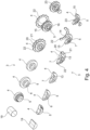
- the Figure 5 shows the stages of Figure 4 in lateral sectional views and at least partially in plan views of the screw element blank 3.
- the expansion of the lower area 16 of the shaft 5 or the area facing away from the head 4 is relatively small and, accordingly, the formation of the undercut 15 is also relatively small. This is due to the fact that the undercut 15 only serves to secure or arrange a washer in a way that prevents it from being lost or lost.
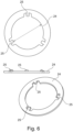
- Fig.6 shows different views of a washer 24 or sliding washer, which together with a screw element blank 3 according to the Fig.4 and 5 to form a nut, in which the washer 24 is arranged in the area of the shaft 5 in a way that prevents loss.
- the radially inward-facing, partially recessed noses 25 formed in the inner circumference are bent upwards or out of the plane of the disk. This deformation of the noses or in the deformed state of the noses ensures that a uniform inner diameter is achieved in the area of the noses 25 or even an inner diameter in the area of the noses 25 that is slightly larger than the rest. Inner diameter of the washer. This is shown, for example, in the top view of the washer 24 of the Fig.6 recognizable.
- the inner diameter is selected at every point so that it is at least slightly larger than the expanded section of a corresponding screw element or blank.
- the washer can be slipped over this section of the shaft and moved up to the head or into the area of the undercut.
- a deformation tool can be used to deform, in particular to deform the lugs 25 back into or into the plane of the washer, whereby they then realize a reduced inner diameter in the area of the lugs 25.
- the inner diameter of the washer 24 is formed smaller, at least in sections, than the outer diameter of the widened region 16 of the shaft 5 due to the reshaping of the lugs 25. This ensures that the washer is arranged on the screw element 3, in particular on the nut, in a loss-proof manner.
Landscapes
- Engineering & Computer Science (AREA)
- Mechanical Engineering (AREA)
- General Engineering & Computer Science (AREA)
- Forging (AREA)
Claims (24)
- Procédé pour la production d'un élément de vissage ou d'une ébauche (3) d'élément de vissage, ledit procédé comprenant une étape de procédé dans laquelle une ébauche (3) ayant une tige cylindrique (5) formée sur une tête (4) est générée, et un trou borgne (7) étant formé dans l'ébauche (3) à partir d'un côté supérieur (11) de la tête (4) détourné de la tige (5) dans une étape de procédé, notamment supplémentaire, ledit trou borgne (7) s'étendant dans la direction de la tige (5) et formant au moins une première section (13), notamment ayant une section transversale (Q1) polygonale, de préférence pour recevoir un outil de vissage ou ayant une section transversale (Q1) ronde, de préférence comme précurseur d'une ouverture de vissage (23), et
caractérisé en ce que
le trou borgne (7) est approfondi en formant au moins une deuxième section (14) adjacente à la première section (13) dans une étape de procédé suivante, la deuxième section (14) formant une section transversale (Q2) qui est de préférence au moins constante par sections et qui est notamment inférieure par rapport à la première section transversale (Q1), la tige (5) étant élargie par sections en formant une contre-dépouille (15) à la jonction entre la tige (5) et la tête (4) en déplaçant au moins indirectement du matériau d'au moins la deuxième section (14) du trou borgne (7) dans l'étape de procédé suivante. - Procédé selon la revendication 1,
caractérisé en ce que
la tige (5) est élargie au moins dans une zone (16) opposée à la tête (4). - Procédé selon la revendication 1 ou 2,
caractérisé en ce
qu'une partie de la section élargie (16) prend appui contre un outil ou une partie d'outil (2.4) de déformation radiaux après l'achèvement de l'étape de procédé suivante tandis que la partie de la tige (5) formant la contre-dépouille (15) forme une distance augmentant axialement vers la tête (4) par rapport à l'outil ou la partie d'outil (2.4) de déformation radiaux. - Procédé selon l'une quelconque des revendications 1 à 3,
caractérisé en ce
qu'une face frontale plane de la tige (5) détournée de la tête (4) ou une face frontal de la tige (5) pourvue d'un prolongement s'étendant axialement de manière à se détourner de la face frontale sont maintenues ou formées dans le cadre de l'étape de procédé suivante. - Procédé selon l'une quelconque des revendications 1 à 4,
caractérisé en ce
qu'une surface d'étanchéité (10) annulaire formée sur un côté inférieur (9) de la tête (4) orienté vers la tige (5) pour venir en contact avec une surface d'appui d'un corps de réception en formant une rainure annulaire coaxiale qui est délimitée radialement vers l'extérieur par une paroi annulaire périphérique. - Procédé selon l'une quelconque des revendications 1 à 3,
caractérisé en ce
qu'une rondelle est disposée dans la zone de la contre-dépouille (15), la rondelle étant déformée de manière que le diamètre intérieur est légèrement supérieure au diamètre extérieur de la contre-dépouille et est inférieur au diamètre extérieur de la section élargie (16) de la tige (5) après la déformation. - Procédé selon l'une quelconque des revendications 1 à 6,
caractérisé en ce
qu'un élargissement maximal de 2 % à 9 %, notamment de 5 % à 7 %, par rapport au diamètre de la tige est généré dans l'étape de procédé suivante. - Procédé selon l'une quelconque des revendications 1 à 7,
caractérisé en ce que
le trou borgne (7) est réalisé de manière qu'un fond (18) de la, notamment deuxième section (14) du trou borgne (7) s'étend jusqu'à 80 %, de préférence 75 %, de manière particulièrement préférée jusqu'à 70 %, plus préférentiellement jusqu'à 45 %, de la hauteur totale de l'élément de vissage à partir du côté supérieur (11) de la tête (4) après l'exécution de l'étape de procédé suivante. - Procédé selon l'une quelconque des revendications 1 à 8,
caractérisé en ce que
la première section (13) du trou borgne (7) est réalisée de manière qu'un fond de la première section (13) du trou borgne (7) s'étend jusqu'à 70 %, de préférence 65 %, de manière particulièrement préférée jusqu'à 40 %, de la hauteur totale de l'élément de vissage à partir du côté supérieur (11) de la tête (4). - Procédé selon l'une quelconque des revendications 1 à 3 ou 6 à 9,
caractérisé en ce que
la formation de la première section du trou borgne est effectuée en deux ou plusieurs étapes partielles, de préférence, 70 %, plus préférentiellement 80 %, de la profondeur totale du trou borgne étant produite dans une première étape partielle. - Procédé selon l'une quelconque des revendications 1 à 5 ou 7 à 9, caractérisé en ce que
la deuxième section (14) du trou borgne (7) est réalisée de telle manière dans le cadre de l'étape de procédé suivante qu'un fond (18) de la, notamment deuxième section (14) du trou borgne (7) est formé dans la direction axiale (A) dans une zone (16) d'un élargissement radial maximal. - Procédé selon l'une quelconque des revendications 1 à 3 ou 6 à 10, caractérisé en ce
qu'un fond (18) de la, notamment deuxième section (14) du trou borgne (7) est formé dans la direction axiale (A) dans la tête (4) pour produire un élément de vissage sous la forme d'un écrou ou d'un écrou de vis. - Procédé selon l'une quelconque des revendications 1 à 5, 7 à 9 ou 11, caractérisé en ce que
la tige (5), notamment la surface de la tige, est pourvue d'un filet, notamment au moyen de procédés sans usinage par enlèvement de copeaux, de manière particulièrement préférée, au moyen de roulement ou de laminage, le filet étant réalisé par rapport à l'élargissement et à la contre-dépouille (15) de manière que le filet se termine complètement dans la zone de la contre-dépouille (15). - Procédé selon l'une quelconque des revendications 1 à 3, 6 à 10 ou 12,
caractérisé en ce que
le matériau entre le fond de la deuxième section (14) et une face frontale de la tige (5) détournée de la tête (4) est poinçonné ou estampé, notamment en maintenant la contre-dépouille, dans une étape de génération d'un trou. - Procédé selon la revendication 14,
caractérisé en ce
qu'un filetage femelle, qui s'étend, de préférence, de la tête (4) à une face frontale de la tige (5) détournée de la tête (4), est généré, notamment au moyen d'usinage par enlèvement de copeaux, dans le trou généré dans l'étape de génération du trou. - Procédé selon l'une quelconque des revendications 1 à 3, 6 à 10, 12, 14 ou 15,
caractérisé en ce
qu'une partie de prise d'outil, notamment une polygone extérieure, est formée dans une étape de procédé, de préférence après la formation de la première section du trou borgne dans la zone de la tête (4), ladite partie de prise d'outil s'étendant, de préférence, sur toute la hauteur de la tête (4) au moins après un processus d'ébarbage suivant. - Ébauche d'élément de vissage, notamment produite selon un procédé selon la revendication 11, ladite ébauche d'élément de vissage ayant une tête (4) et une tige cylindrique (5) formée sur la tête (4), un trou borgne (7) s'étendant à partir de la tête (4) vers la tige (5) et ayant au moins une première section (13), notamment ayant une section transversale (Q1) polygonale, de préférence pour recevoir un outil de vissage ou ayant une section transversale (Q1) ronde, de préférence comme précurseur d'une ouverture de vissage (23), et la tige (5) ayant une contre-dépouille (15) à la jonction avec la tête (4),
caractérisée en ce que
le trou borgne (7) a une deuxième section (14) adjacente à la première section (13), la deuxième section (14) formant une section transversale (Q2) qui est de préférence au moins constante par sections et qui est notamment inférieure par rapport à la première section transversale (Q1), la contre-dépouille (15) étant formée par un élargissement formé sur une partie de la tige (5) à la jonction entre la tige (5) et la tête de vis (4) en déplaçant au moins indirectement du matériau d'au moins la deuxième section (14) du trou borgne (7), un fond (18) de la deuxième section (14) du trou borgne (7) s'étendant dans la direction axiale (A) dans une zone (16) d'un élargissement radial maximal, un flanc uniforme étant formé comme jonction entre une zone élargie et une zone non élargie du diamètre de la tige. - Ébauche d'élément de vissage selon la revendication 17,
caractérisée en ce que
la tige (5) a l'élargissement au moins dans une zone (16) opposée à la tête de vis (4). - Ébauche d'élément de vissage selon la revendication 17 ou 18,
caractérisée par
une face frontale plane de la tige (5) détournée de la tête (4) ou une face frontal de la tige (5) pourvue d'un prolongement s'étendant axialement à partir de la face frontale. - Ébauche d'élément de vissage selon l'une quelconque des revendications 17 à 19,
caractérisée par
une surface d'étanchéité (10) annulaire formée sur un côté inférieur (9) de la tête (4) orienté vers la tige (5) pour venir en contact avec une surface d'appui d'un corps de réception en formant une rainure annulaire coaxiale qui est délimitée radialement vers l'extérieur par une paroi annulaire périphérique. - Ébauche d'élément de vissage selon l'une quelconque des revendications 17 à 20,
caractérisée en ce
qu'un élargissement maximal est de 2 % à 9 %, notamment de 5 % à 7 %, par rapport au diamètre de la tige, notamment à la jonction avec la tête (4). - Ébauche d'élément de vissage selon l'une quelconque des revendications 17 à 21,
caractérisée en ce
qu'un fond (18) de la, notamment deuxième section (14) du trou borgne (7) s'étend jusqu'à 80 %, de préférence 75 %, de manière particulièrement préférée jusqu'à 70 %, de la hauteur totale de la vis à partir du côté supérieur (11) de la tête (4). - Ébauche d'élément de vissage selon l'une quelconque des revendications 17 à 22,
caractérisée en ce que
le trou borgne (7) a une troisième section (17) adjacente à la deuxième section (14), ladite troisième section (17) étant concentrique par rapport à la première section (13) et/ou la deuxième section (14) et formant un segment de cône qui se rétrécisse dans la direction (A) de la tige (5) et débouche notamment dans un fond (18) plan du trou borgne (7) qui s'étend parallèlement par rapport au côté supérieur (11). - Élément de vissage, notamment une vis d'étanchéité,
caractérisé en ce
qu'il est produit à partir d'une ébauche d'élément de vissage selon l'une quelconque des revendications 17 à 23, l'élément de vissage ayant une tête (4) et une tige cylindrique (5) formée sur la tête (4), un trou borgne (7) s'étendant à partir de la tête (4) vers la tige (5) et ayant au moins une première section (13), notamment ayant une section transversale (Q1) polygonale, de préférence pour recevoir un outil de vissage, et la tige (5) ayant une contre-dépouille (15) à la jonction avec la tête (4), le trou borgne (7) ayant une deuxième section (14) adjacente à la première section (13), la deuxième section (14) ayant une section transversale (Q2) qui est de préférence au moins constante par sections et qui est notamment inférieure par rapport à la première section transversale (Q1), la contre-dépouille (15) étant formée par un élargissement formé sur une partie de la tige (5) à la jonction entre la tige (5) et la tête de vis (4) en déplaçant au moins indirectement du matériau d'au moins la deuxième section (14) du trou borgne (7), un fond (18) de la deuxième section (14) du trou borgne (7) s'étendant dans la direction axiale (A) dans une zone (16) d'un élargissement radial maximal, un flanc uniforme étant formé comme jonction entre une zone élargie et une zone non élargie du diamètre de la tige, la tige (5), notamment la surface de la tige, ayant un filet, notamment un filetage mâle, le filet étant réalisé par rapport à l'élargissement et la contre-dépouille (15) de manière que le filet se termine complètement dans la zone de la contre-dépouille (15).
Applications Claiming Priority (2)
| Application Number | Priority Date | Filing Date | Title |
|---|---|---|---|
| DE102019116338.2A DE102019116338B3 (de) | 2019-06-17 | 2019-06-17 | Verfahren zur Herstellung eines Schraubelementrohlings sowie eines Schraubelements und Schraubelementrohling sowie Schraubelement |
| PCT/EP2020/061011 WO2020254011A1 (fr) | 2019-06-17 | 2020-04-20 | Procédé de fabrication d'une forme de départ d'élément de visserie ainsi que d'un élément de visserie, et forme de départ d'élément de visserie ainsi qu'élément de visserie |
Publications (3)
| Publication Number | Publication Date |
|---|---|
| EP3983149A1 EP3983149A1 (fr) | 2022-04-20 |
| EP3983149B1 true EP3983149B1 (fr) | 2024-09-25 |
| EP3983149C0 EP3983149C0 (fr) | 2024-09-25 |
Family
ID=70617065
Family Applications (1)
| Application Number | Title | Priority Date | Filing Date |
|---|---|---|---|
| EP20724750.3A Active EP3983149B1 (fr) | 2019-06-17 | 2020-04-20 | Procédé de fabrication d'une forme de départ d'élément de visserie ainsi que d'un élément de visserie, et forme de départ d'élément de visserie ainsi qu'élément de visserie |
Country Status (5)
| Country | Link |
|---|---|
| US (1) | US20220362834A1 (fr) |
| EP (1) | EP3983149B1 (fr) |
| CN (1) | CN114126780B (fr) |
| DE (1) | DE102019116338B3 (fr) |
| WO (1) | WO2020254011A1 (fr) |
Families Citing this family (1)
| Publication number | Priority date | Publication date | Assignee | Title |
|---|---|---|---|---|
| WO2023278169A2 (fr) * | 2021-07-02 | 2023-01-05 | Phillips Screw Company | Outil et élément de fixation pour réduire le décapage |
Citations (1)
| Publication number | Priority date | Publication date | Assignee | Title |
|---|---|---|---|---|
| WO2005099930A1 (fr) * | 2004-04-13 | 2005-10-27 | Profil-Verbindungstechnik Gmbh & Co. Kg | Procede de production d'elements a corps creux, element a corps creux correspondant, composant d'assemblage et outil composite progressif pour la mise en oeuvre de ce procede |
Family Cites Families (17)
| Publication number | Priority date | Publication date | Assignee | Title |
|---|---|---|---|---|
| JPH0829392B2 (ja) * | 1993-12-17 | 1996-03-27 | 有限会社新城製作所 | ピアスナットの製造装置 |
| PL347401A1 (en) * | 2001-05-07 | 2002-11-18 | Piotr Loniewski | Oil drain for an internal combustion engine, in particular that used in automotive vehicles, device for and method o draining off used engine oil from an oil sump of internal combustion engine, in particular of that used in automotive vehicles |
| JP2003307207A (ja) * | 2002-04-12 | 2003-10-31 | Masakatsu Oonishi | トルク規定ナット |
| DE10321544A1 (de) * | 2002-12-16 | 2004-07-01 | Hartmut Flaig | Verschlussschraube aus metallischem Werkstoff, Verfahren zu deren Herstellung, Rohling dafür sowie Werkzeug dazu |
| US20060153661A1 (en) * | 2002-12-16 | 2006-07-13 | Hartmut Flaig | Screw plug made of a metallic material, method for the production thereof, corresponding blank and corresponding tool |
| FR2852870B1 (fr) * | 2003-03-24 | 2005-06-10 | Bollhoff Otalu Sa | Procede de fabrication d'un ecrou noye a sertir et ecrou noye a sertir realise par un tel procede. |
| DE102006046631B4 (de) * | 2006-09-29 | 2010-06-10 | Hartmut Flaig | Verschlussschraube mit Ringnut sowie Herstellungsverfahren |
| DE102008038185B3 (de) * | 2008-08-19 | 2010-01-28 | Sieber Forming Solutions Gmbh | Verfahren und Vorrichtung zur Herstellung von Befestigungs- oder Verbindungsmitteln mit radialen Außenkonturen, insbesondere Schrauben oder Gewindebolzen |
| KR20110084215A (ko) * | 2008-10-03 | 2011-07-21 | 지베르 포밍 솔류션 게엠바하 | 중공형 금속 소재 상의 외부 쓰레드의 비절삭 제조방법 및 장치 |
| DE102011107236A1 (de) * | 2011-07-13 | 2012-05-31 | Daimler Ag | Schraubelement |
| DE102014118342A1 (de) * | 2013-12-17 | 2015-06-18 | Richard Bergner Verbindungstechnik Gmbh & Co. Kg | Verfahren zur unverlierbaren Aufbringung einer Unterlegscheibe auf den Schaft einer Schraube |
| DE202013105922U1 (de) * | 2013-12-23 | 2015-03-24 | Hartmut Flaig | Dichtschraube sowie Dichtanordnung |
| CN105081189B (zh) * | 2015-09-17 | 2017-12-15 | 宾科汽车紧固件(昆山)有限公司 | 镍铜合金拉铆螺母冷镦装置及生产工艺 |
| US10001039B2 (en) * | 2016-08-09 | 2018-06-19 | Hyundal SHIN | Drain bolt configured to be forcibly withdrawn |
| DE102016012551A1 (de) * | 2016-10-20 | 2018-04-26 | Florian Heinrichs | Schraube mit Ringdichtung |
| US11542979B2 (en) * | 2017-11-30 | 2023-01-03 | Abb Schweiz Ag | Seal arrangement, kit of parts and method |
| CN108266445B (zh) * | 2018-02-06 | 2024-06-04 | 宾科汽车紧固件(昆山)有限公司 | 防水铆螺母及其生产工艺 |
-
2019
- 2019-06-17 DE DE102019116338.2A patent/DE102019116338B3/de active Active
-
2020
- 2020-04-20 CN CN202080051315.2A patent/CN114126780B/zh active Active
- 2020-04-20 EP EP20724750.3A patent/EP3983149B1/fr active Active
- 2020-04-20 WO PCT/EP2020/061011 patent/WO2020254011A1/fr not_active Ceased
- 2020-04-20 US US17/620,166 patent/US20220362834A1/en active Pending
Patent Citations (1)
| Publication number | Priority date | Publication date | Assignee | Title |
|---|---|---|---|---|
| WO2005099930A1 (fr) * | 2004-04-13 | 2005-10-27 | Profil-Verbindungstechnik Gmbh & Co. Kg | Procede de production d'elements a corps creux, element a corps creux correspondant, composant d'assemblage et outil composite progressif pour la mise en oeuvre de ce procede |
Also Published As
| Publication number | Publication date |
|---|---|
| CN114126780B (zh) | 2024-09-24 |
| CN114126780A (zh) | 2022-03-01 |
| DE102019116338B3 (de) | 2020-08-20 |
| EP3983149A1 (fr) | 2022-04-20 |
| US20220362834A1 (en) | 2022-11-17 |
| EP3983149C0 (fr) | 2024-09-25 |
| WO2020254011A1 (fr) | 2020-12-24 |
Similar Documents
| Publication | Publication Date | Title |
|---|---|---|
| DE69419890T2 (de) | Vorrichtung zur Herstellung selbststanzender Muttern | |
| EP0993902B1 (fr) | Procédé pour attacher un élément fonctionnel, matrice, élément fonctionnel et ensemble de montage | |
| DE69507348T2 (de) | Selbstsicherndes Befestigungselement und Verfahren zu dessen Herstellung und Einbau | |
| EP0894986B1 (fr) | Rivet aveugle | |
| DE102016204619B4 (de) | Einpressverbindung zwischen einem hochfesten Bauteil und einem Einpresselement, Verfahren zur Ausbildung einer solchen Einpressverbindung sowie Einpresselement für eine solche Einpressverbindung | |
| EP2980426A1 (fr) | Composant d'assemblage comprenant un element a sertir et une partie de tole | |
| EP1188937A2 (fr) | Vis hexalobulaire et procédé pour sa fabrication | |
| EP2181783B1 (fr) | Tige cannelée avec rebord d'extrêmité roulé et son procédé de fabrication | |
| WO2017157959A1 (fr) | Elément d'insertion à force autoperforant, assemblage par insertion à force et procédé pour réaliser un tel assemblage par insertion à force | |
| EP0535193B1 (fr) | Procede pour la fabrication d'une section de tige cylindrique non filetee d'une extremite de fixation ou d'une partie d'extremite de fixation | |
| DE202017105715U1 (de) | Einpressverbindung zwischen einem hochfesten Bauteil und einem Einpresselement sowie Einpresselement für eine solche Einpressverbindung | |
| DE102019116338B3 (de) | Verfahren zur Herstellung eines Schraubelementrohlings sowie eines Schraubelements und Schraubelementrohling sowie Schraubelement | |
| EP3964726B1 (fr) | Accouplement cannelé et procédé de fabrication d'un maneton d'essieu cannelé | |
| DE10343930B4 (de) | Bauteil mit einem eingepressten Einpresselement sowie Einpresselement und Verfahren zum Einpressen eines Einpresselements | |
| DE102009025525A1 (de) | Verfahren zum Ausbilden einer Einpressverbindung zwischen einem Fügeelement und einem Werkstück, Einpressverbindung sowie Fügeelement | |
| EP1953397B1 (fr) | Vis de cisaillement et son procédé de fabrication | |
| WO2010115502A1 (fr) | Rotor pourvu d'une sécurité contre la surcharge pour une limitation du couple de rotation | |
| EP3936730B1 (fr) | Élément fonctionnel | |
| EP1376764A2 (fr) | Vis à amorces de rupture multiples | |
| DE19581042B4 (de) | Verfahren zum Herstellen eines Teils mit einer Hinterschneidung | |
| EP1591676B1 (fr) | Elément rapporté à enfoncement automatique pour tôle | |
| EP4337401B1 (fr) | Ébauche d'écrou de vis pour la fabrication d'un écrou de fixation | |
| DE102007004119A1 (de) | Stanzmutter | |
| DE69303683T2 (de) | Verfahren zur Herstellung eines rohrförmigen Körpers mit einer verformbaren inneren Lippe | |
| DE102018210893A1 (de) | Schraubelement und Verfahren zum Herstellen eines solchen Schraubelements |
Legal Events
| Date | Code | Title | Description |
|---|---|---|---|
| STAA | Information on the status of an ep patent application or granted ep patent |
Free format text: STATUS: UNKNOWN |
|
| STAA | Information on the status of an ep patent application or granted ep patent |
Free format text: STATUS: THE INTERNATIONAL PUBLICATION HAS BEEN MADE |
|
| PUAI | Public reference made under article 153(3) epc to a published international application that has entered the european phase |
Free format text: ORIGINAL CODE: 0009012 |
|
| STAA | Information on the status of an ep patent application or granted ep patent |
Free format text: STATUS: REQUEST FOR EXAMINATION WAS MADE |
|
| 17P | Request for examination filed |
Effective date: 20211220 |
|
| AK | Designated contracting states |
Kind code of ref document: A1 Designated state(s): AL AT BE BG CH CY CZ DE DK EE ES FI FR GB GR HR HU IE IS IT LI LT LU LV MC MK MT NL NO PL PT RO RS SE SI SK SM TR |
|
| DAV | Request for validation of the european patent (deleted) | ||
| DAX | Request for extension of the european patent (deleted) | ||
| STAA | Information on the status of an ep patent application or granted ep patent |
Free format text: STATUS: EXAMINATION IS IN PROGRESS |
|
| 17Q | First examination report despatched |
Effective date: 20230203 |
|
| GRAP | Despatch of communication of intention to grant a patent |
Free format text: ORIGINAL CODE: EPIDOSNIGR1 |
|
| STAA | Information on the status of an ep patent application or granted ep patent |
Free format text: STATUS: GRANT OF PATENT IS INTENDED |
|
| INTG | Intention to grant announced |
Effective date: 20240502 |
|
| GRAS | Grant fee paid |
Free format text: ORIGINAL CODE: EPIDOSNIGR3 |
|
| GRAA | (expected) grant |
Free format text: ORIGINAL CODE: 0009210 |
|
| STAA | Information on the status of an ep patent application or granted ep patent |
Free format text: STATUS: THE PATENT HAS BEEN GRANTED |
|
| AK | Designated contracting states |
Kind code of ref document: B1 Designated state(s): AL AT BE BG CH CY CZ DE DK EE ES FI FR GB GR HR HU IE IS IT LI LT LU LV MC MK MT NL NO PL PT RO RS SE SI SK SM TR |
|
| REG | Reference to a national code |
Ref country code: GB Ref legal event code: FG4D Free format text: NOT ENGLISH |
|
| REG | Reference to a national code |
Ref country code: CH Ref legal event code: EP |
|
| REG | Reference to a national code |
Ref country code: DE Ref legal event code: R096 Ref document number: 502020009330 Country of ref document: DE |
|
| REG | Reference to a national code |
Ref country code: IE Ref legal event code: FG4D Free format text: LANGUAGE OF EP DOCUMENT: GERMAN |
|
| U01 | Request for unitary effect filed |
Effective date: 20241021 |
|
| U07 | Unitary effect registered |
Designated state(s): AT BE BG DE DK EE FI FR IT LT LU LV MT NL PT RO SE SI Effective date: 20241104 |
|
| PG25 | Lapsed in a contracting state [announced via postgrant information from national office to epo] |
Ref country code: NO Free format text: LAPSE BECAUSE OF FAILURE TO SUBMIT A TRANSLATION OF THE DESCRIPTION OR TO PAY THE FEE WITHIN THE PRESCRIBED TIME-LIMIT Effective date: 20241225 |
|
| PG25 | Lapsed in a contracting state [announced via postgrant information from national office to epo] |
Ref country code: GR Free format text: LAPSE BECAUSE OF FAILURE TO SUBMIT A TRANSLATION OF THE DESCRIPTION OR TO PAY THE FEE WITHIN THE PRESCRIBED TIME-LIMIT Effective date: 20241226 |
|
| PG25 | Lapsed in a contracting state [announced via postgrant information from national office to epo] |
Ref country code: RS Free format text: LAPSE BECAUSE OF FAILURE TO SUBMIT A TRANSLATION OF THE DESCRIPTION OR TO PAY THE FEE WITHIN THE PRESCRIBED TIME-LIMIT Effective date: 20241225 |
|
| PG25 | Lapsed in a contracting state [announced via postgrant information from national office to epo] |
Ref country code: RS Free format text: LAPSE BECAUSE OF FAILURE TO SUBMIT A TRANSLATION OF THE DESCRIPTION OR TO PAY THE FEE WITHIN THE PRESCRIBED TIME-LIMIT Effective date: 20241225 Ref country code: NO Free format text: LAPSE BECAUSE OF FAILURE TO SUBMIT A TRANSLATION OF THE DESCRIPTION OR TO PAY THE FEE WITHIN THE PRESCRIBED TIME-LIMIT Effective date: 20241225 Ref country code: GR Free format text: LAPSE BECAUSE OF FAILURE TO SUBMIT A TRANSLATION OF THE DESCRIPTION OR TO PAY THE FEE WITHIN THE PRESCRIBED TIME-LIMIT Effective date: 20241226 |
|
| PG25 | Lapsed in a contracting state [announced via postgrant information from national office to epo] |
Ref country code: IS Free format text: LAPSE BECAUSE OF FAILURE TO SUBMIT A TRANSLATION OF THE DESCRIPTION OR TO PAY THE FEE WITHIN THE PRESCRIBED TIME-LIMIT Effective date: 20250125 |
|
| PG25 | Lapsed in a contracting state [announced via postgrant information from national office to epo] |
Ref country code: SM Free format text: LAPSE BECAUSE OF FAILURE TO SUBMIT A TRANSLATION OF THE DESCRIPTION OR TO PAY THE FEE WITHIN THE PRESCRIBED TIME-LIMIT Effective date: 20240925 |
|
| PG25 | Lapsed in a contracting state [announced via postgrant information from national office to epo] |
Ref country code: ES Free format text: LAPSE BECAUSE OF FAILURE TO SUBMIT A TRANSLATION OF THE DESCRIPTION OR TO PAY THE FEE WITHIN THE PRESCRIBED TIME-LIMIT Effective date: 20240925 |
|
| PG25 | Lapsed in a contracting state [announced via postgrant information from national office to epo] |
Ref country code: CZ Free format text: LAPSE BECAUSE OF FAILURE TO SUBMIT A TRANSLATION OF THE DESCRIPTION OR TO PAY THE FEE WITHIN THE PRESCRIBED TIME-LIMIT Effective date: 20240925 Ref country code: PL Free format text: LAPSE BECAUSE OF FAILURE TO SUBMIT A TRANSLATION OF THE DESCRIPTION OR TO PAY THE FEE WITHIN THE PRESCRIBED TIME-LIMIT Effective date: 20240925 |
|
| PG25 | Lapsed in a contracting state [announced via postgrant information from national office to epo] |
Ref country code: SK Free format text: LAPSE BECAUSE OF FAILURE TO SUBMIT A TRANSLATION OF THE DESCRIPTION OR TO PAY THE FEE WITHIN THE PRESCRIBED TIME-LIMIT Effective date: 20240925 |
|
| U20 | Renewal fee for the european patent with unitary effect paid |
Year of fee payment: 6 Effective date: 20250428 |
|
| PLBE | No opposition filed within time limit |
Free format text: ORIGINAL CODE: 0009261 |
|
| STAA | Information on the status of an ep patent application or granted ep patent |
Free format text: STATUS: NO OPPOSITION FILED WITHIN TIME LIMIT |
|
| 26N | No opposition filed |
Effective date: 20250626 |
|
| REG | Reference to a national code |
Ref country code: CH Ref legal event code: H13 Free format text: ST27 STATUS EVENT CODE: U-0-0-H10-H13 (AS PROVIDED BY THE NATIONAL OFFICE) Effective date: 20251125 |
|
| PG25 | Lapsed in a contracting state [announced via postgrant information from national office to epo] |
Ref country code: MC Free format text: LAPSE BECAUSE OF FAILURE TO SUBMIT A TRANSLATION OF THE DESCRIPTION OR TO PAY THE FEE WITHIN THE PRESCRIBED TIME-LIMIT Effective date: 20240925 |
|
| GBPC | Gb: european patent ceased through non-payment of renewal fee |
Effective date: 20250420 |
|
| PG25 | Lapsed in a contracting state [announced via postgrant information from national office to epo] |
Ref country code: GB Free format text: LAPSE BECAUSE OF NON-PAYMENT OF DUE FEES Effective date: 20250420 |
|
| PG25 | Lapsed in a contracting state [announced via postgrant information from national office to epo] |
Ref country code: HR Free format text: LAPSE BECAUSE OF FAILURE TO SUBMIT A TRANSLATION OF THE DESCRIPTION OR TO PAY THE FEE WITHIN THE PRESCRIBED TIME-LIMIT Effective date: 20240925 |
|
| PG25 | Lapsed in a contracting state [announced via postgrant information from national office to epo] |
Ref country code: CH Free format text: LAPSE BECAUSE OF NON-PAYMENT OF DUE FEES Effective date: 20250430 |
|
| PG25 | Lapsed in a contracting state [announced via postgrant information from national office to epo] |
Ref country code: IE Free format text: LAPSE BECAUSE OF NON-PAYMENT OF DUE FEES Effective date: 20250420 |