EP3984458B1 - Commande simultanée basée sur les gestes pour un dispositif technique médical - Google Patents
Commande simultanée basée sur les gestes pour un dispositif technique médical Download PDFInfo
- Publication number
- EP3984458B1 EP3984458B1 EP20201566.5A EP20201566A EP3984458B1 EP 3984458 B1 EP3984458 B1 EP 3984458B1 EP 20201566 A EP20201566 A EP 20201566A EP 3984458 B1 EP3984458 B1 EP 3984458B1
- Authority
- EP
- European Patent Office
- Prior art keywords
- command
- unit
- command communication
- facility
- operator
- Prior art date
- Legal status (The legal status is an assumption and is not a legal conclusion. Google has not performed a legal analysis and makes no representation as to the accuracy of the status listed.)
- Active
Links
Images


Classifications
-
- A—HUMAN NECESSITIES
- A61—MEDICAL OR VETERINARY SCIENCE; HYGIENE
- A61B—DIAGNOSIS; SURGERY; IDENTIFICATION
- A61B8/00—Diagnosis using ultrasonic, sonic or infrasonic waves
- A61B8/46—Ultrasonic, sonic or infrasonic diagnostic devices with special arrangements for interfacing with the operator or the patient
- A61B8/467—Ultrasonic, sonic or infrasonic diagnostic devices with special arrangements for interfacing with the operator or the patient characterised by special input means
-
- G—PHYSICS
- G06—COMPUTING OR CALCULATING; COUNTING
- G06F—ELECTRIC DIGITAL DATA PROCESSING
- G06F3/00—Input arrangements for transferring data to be processed into a form capable of being handled by the computer; Output arrangements for transferring data from processing unit to output unit, e.g. interface arrangements
- G06F3/01—Input arrangements or combined input and output arrangements for interaction between user and computer
- G06F3/017—Gesture based interaction, e.g. based on a set of recognized hand gestures
-
- A—HUMAN NECESSITIES
- A43—FOOTWEAR
- A43B—CHARACTERISTIC FEATURES OF FOOTWEAR; PARTS OF FOOTWEAR
- A43B17/00—Insoles for insertion, e.g. footbeds or inlays, for attachment to the shoe after the upper has been joined
-
- A—HUMAN NECESSITIES
- A43—FOOTWEAR
- A43B—CHARACTERISTIC FEATURES OF FOOTWEAR; PARTS OF FOOTWEAR
- A43B3/00—Footwear characterised by the shape or the use
- A43B3/34—Footwear characterised by the shape or the use with electrical or electronic arrangements
-
- A—HUMAN NECESSITIES
- A43—FOOTWEAR
- A43B—CHARACTERISTIC FEATURES OF FOOTWEAR; PARTS OF FOOTWEAR
- A43B3/00—Footwear characterised by the shape or the use
- A43B3/34—Footwear characterised by the shape or the use with electrical or electronic arrangements
- A43B3/38—Footwear characterised by the shape or the use with electrical or electronic arrangements with power sources
-
- A—HUMAN NECESSITIES
- A61—MEDICAL OR VETERINARY SCIENCE; HYGIENE
- A61B—DIAGNOSIS; SURGERY; IDENTIFICATION
- A61B5/00—Measuring for diagnostic purposes; Identification of persons
- A61B5/68—Arrangements of detecting, measuring or recording means, e.g. sensors, in relation to patient
- A61B5/6801—Arrangements of detecting, measuring or recording means, e.g. sensors, in relation to patient specially adapted to be attached to or worn on the body surface
-
- A—HUMAN NECESSITIES
- A61—MEDICAL OR VETERINARY SCIENCE; HYGIENE
- A61B—DIAGNOSIS; SURGERY; IDENTIFICATION
- A61B5/00—Measuring for diagnostic purposes; Identification of persons
- A61B5/74—Details of notification to user or communication with user or patient; User input means
- A61B5/7475—User input or interface means, e.g. keyboard, pointing device, joystick
-
- A—HUMAN NECESSITIES
- A61—MEDICAL OR VETERINARY SCIENCE; HYGIENE
- A61B—DIAGNOSIS; SURGERY; IDENTIFICATION
- A61B6/00—Apparatus or devices for radiation diagnosis; Apparatus or devices for radiation diagnosis combined with radiation therapy equipment
- A61B6/10—Safety means specially adapted therefor
-
- A—HUMAN NECESSITIES
- A61—MEDICAL OR VETERINARY SCIENCE; HYGIENE
- A61B—DIAGNOSIS; SURGERY; IDENTIFICATION
- A61B6/00—Apparatus or devices for radiation diagnosis; Apparatus or devices for radiation diagnosis combined with radiation therapy equipment
- A61B6/46—Arrangements for interfacing with the operator or the patient
- A61B6/467—Arrangements for interfacing with the operator or the patient characterised by special input means
-
- A—HUMAN NECESSITIES
- A61—MEDICAL OR VETERINARY SCIENCE; HYGIENE
- A61B—DIAGNOSIS; SURGERY; IDENTIFICATION
- A61B6/00—Apparatus or devices for radiation diagnosis; Apparatus or devices for radiation diagnosis combined with radiation therapy equipment
- A61B6/54—Control of apparatus or devices for radiation diagnosis
- A61B6/548—Remote control of the apparatus or devices
-
- G—PHYSICS
- G06—COMPUTING OR CALCULATING; COUNTING
- G06F—ELECTRIC DIGITAL DATA PROCESSING
- G06F3/00—Input arrangements for transferring data to be processed into a form capable of being handled by the computer; Output arrangements for transferring data from processing unit to output unit, e.g. interface arrangements
- G06F3/16—Sound input; Sound output
- G06F3/167—Audio in a user interface, e.g. using voice commands for navigating, audio feedback
-
- G—PHYSICS
- G16—INFORMATION AND COMMUNICATION TECHNOLOGY [ICT] SPECIALLY ADAPTED FOR SPECIFIC APPLICATION FIELDS
- G16H—HEALTHCARE INFORMATICS, i.e. INFORMATION AND COMMUNICATION TECHNOLOGY [ICT] SPECIALLY ADAPTED FOR THE HANDLING OR PROCESSING OF MEDICAL OR HEALTHCARE DATA
- G16H30/00—ICT specially adapted for the handling or processing of medical images
Definitions
- the invention relates to a command transmission device.
- the invention also relates to a command transmission system.
- the invention relates to a command transmission method.
- CT computer tomography
- PET scanners magnetic resonance imaging
- X-ray imaging with C-arm systems examples include computer tomography (CT), magnetic resonance imaging, the use of so-called PET scanners and X-ray imaging with C-arm systems.
- a medical technical assistant MTA
- a radiologist a radiologist
- a doctor instructs the device to be activated by means of a manual input.
- Conventional means for manually entering an activation command into a medical device are switches, keys or buttons and knobs, whereby the switches, keys, buttons and knobs are usually arranged directly on or at the medical device.
- the activation means mentioned can also be connected to a medical device via an electrical cable connection or an electromagnetic radio connection.
- additional interfaces for interaction between an operator and a medical device such as a push button, can be used.
- the input units mentioned are usually part of an operating module.
- control modules are usually located on the floor and can therefore easily become dirty, contaminated with organic substances, especially body fluids, and also easily damaged by tripping over them.
- an operator usually has to be in the immediate vicinity of such an operating module, for example a foot switch.
- an operating module for example a foot switch.
- the operator is tied to a specific location if he or she wants to activate a specific medical device.
- a typical operating module for activating a medical device is a foot switch.
- the problem with such a standard foot switch is that it requires at least one electrical cable for power supply or data transmission, which runs across the floor of an examination room or operating room and represents a tripping hazard for medical staff.
- Joysticks are also used to operate C-arms, for example. With a joystick, you can change a continuously variable movement, for example, you can perform a small deflection at a low speed and a large deflection at a high speed.
- Joysticks are also used to control movements in the automotive industry, aviation and robotics. Such a joystick can, for example, be positioned at the working height of a seated person and is therefore not subject to as much contamination as a joystick on the floor.
- a joystick has the disadvantage that the user has to use his hands to operate the device and therefore does not have his hands free at the same time, for example to examine or treat a patient.
- Foot controls are also used, which are connected wirelessly to a medical technology system to be controlled. Foot switches are mainly used to carry out switching operations, such as switching radiation on and off or moving a patient table.
- an operator In addition to operating an electromechanical switching element to activate or deactivate a medical device, it is desirable for an operator to be able to control other functions of the medical device. Examples of this include scrolling through images or running through a sequence of images, changing the image contrast, zooming in or out on image displays, or changing other parameters specific to a modality.
- the operation of a radiation release or a movement of a medical device using a foot switch can also be confirmed by voice control, camera-based monitoring or RF-based monitoring of a predetermined gesture.
- Gestures that are recognized by image capture can be made visible, for example, by moving the operator's hands or fingers, whereby the gestures can mean grasping, releasing, moving or zooming.
- the movement of feet or toes can, for example, control an increase in speed, a slowdown, a movement to the left or a movement to the right.
- An eye movement to the left, right, up or down can represent a directional decision.
- a head movement to the left or right can also be used to change direction.
- feedback can be provided by a haptic signal, for example in the form of a vibration, to confirm to the operator that a desired action has been triggered.
- the operator can simultaneously control a medical device and treat a patient. This is made possible by the fact that in order to trigger an action of the medical device, the operator does not have to change position in order to operate an input device. In this way, the operator can trigger an action without losing focus on a current treatment activity.
- the operator can also control a medical device if they need their hands or eyes to treat the patient or operate another medical device, for example by giving commands using foot movements. Such a simultaneous approach can also save on medical personnel.
- the command transmission device has a sensor unit for detecting a physical movement of an operator.
- a sensor unit comprises at least one sensor.
- the sensor is designed to detect a movement. Such a movement can be detected, for example, by one or more acceleration measurements or determine a measurement of a mechanical deformation. The movement can follow a predetermined movement pattern, which is used to generate command information.
- the sensor unit and/or even the entire command transmission device are attached to the operator by a fixing unit. It should be mentioned that the command transmission device is also preferably set up not only to process the sensor data of the internal sensor unit, but also to receive sensor data from external sensors and to evaluate them.
- the fixing unit enables the sensor unit, preferably the command transmission device, to be used as an embedded system, which an operator always carries with them without having to hold a control unit, for example a joystick.
- Part of the command transmission device according to the invention is also an evaluation unit for evaluating the detected movement of the operator and for identifying a command on the basis of the detected movement.
- the evaluation unit preferably comprises a so-called ultra-low-power microcontroller, which can be operated with small amounts of energy, for example by an autonomous energy generation system arranged on or in the command transmission device.
- the sensor data recorded by the sensors are analyzed by the evaluation unit.
- the evaluation unit classifies the recorded movement as to whether it is an intentional or unintentional movement. Such a classification can be carried out, for example, by comparing the recorded movement with one or more reference movements, each of which is assigned to a specific command.
- the sensor unit therefore comprises a mechatronic component with which a movement of an operator can be recorded. If a command is recognized or identified, a control command is issued based on the identified command, for example the identified command itself, is transmitted to a medical device to be operated by a command transmission unit, which is also part of the command transmission device according to the invention.
- the command transmission device is therefore designed as a mobile device in the form of a so-called "smart wearable" which the operator always carries with them.
- Parts or the entire command transmission device can be designed as a so-called embedded system which is specifically designed to control a medical device by movement.
- An operator of a medical device can advantageously control an operating process by any predetermined movement. This makes it possible to perform several tasks in parallel. For example, the operator can examine a patient with their hands and at the same time control a medical device, such as an imaging medical device, with another part of their body.
- the operator always carries the input unit in the form of the command transmission device according to the invention with them so that it cannot get in anyone's way or become a dust collector and the operator does not have to look for it when they want to transmit a command.
- the user's attention can also remain on the current parallel activity while operating a medical device. For example, attention does not have to be diverted from the patient to operate the medical device. For safety-relevant treatment steps that require full attention, no additional staff is therefore required to operate the medical device in parallel.
- analogue functions on different devices can be triggered in the same way or with the same gesture without a user having to find the corresponding differently designed control elements on the individual differently structured devices. In this way, the training time is reduced. For example, there is no need to familiarise yourself with the different user interfaces of different medical devices, since analogue functions can always be controlled in the same way using the same body movements.
- the command transmission device according to the invention advantageously integrates the operation of a medical device intuitively into a workflow. In addition, multiple and reusable use is also possible for different applications if the evaluation unit is designed to be programmable.
- the command transmission system according to the invention has a first command transmission device according to the invention with gesture recognition.
- the first command transmission device according to the invention is fixed to the operator and is designed as a master device for bidirectional data exchange with at least one slave device. This means that the first command transmission device according to the invention functions as a master according to the master-slave principle. Commands can therefore only be transmitted if command transmission has been enabled via the first command transmission device according to the invention.
- the gesture sensor unit of the first command transmission device is activated, i.e. the first command transmission device reacts to gesture control and is configured to transmit a determined command, preferably an initialization command, to a second command transmission device, preferably according to the invention.
- the second command transmission device is also part of the command transmission system according to the invention and is arranged away from the operator, preferably on a medical device to be operated.
- the second command transmission device is designed as a slave device for bidirectional data exchange with a master device and it comprises an evaluation unit which comprises at least one subunit for recognizing command contents based on sensor data.
- the evaluation unit preferably comprises a gesture recognition unit which is activated to detect a gesture of the operator from a distance from the operator.
- the evaluation unit also preferably comprises a speech recognition unit with a speech recognition capability for recognizing speech contents based on acoustic sensor data.
- the evaluation unit therefore has the ability to detect a gesture or acoustic information from the operator from a distance from the operator. These functions can be activated from the first command transmission device designed as a master device.
- the second command transmission device therefore preferably also includes a voice recognition capability with which a voice command from the operator can be evaluated. Furthermore, the second command transmission device is set up to receive a command received from the first command transmission device, for example a voice command, and to transmit a control command to the medical device on the basis of this command or to control it on the basis of the received command.
- the second command transmission device can advantageously be initialized to be ready to receive by a command that was given via the first command transmission device according to the invention, for example initiated by a movement or gesture of the operator.
- the operator then controls the medical device by means of an additional control command which is generated either directly, for example by means of a voice command or a gesture, either directly by detecting the voice command or the gesture by the second command transmission device or by detecting this additional command by the first command transmission device and subsequently transmitting the detected additional command to the second command transmission device, which then controls the medical device in accordance with the received or detected command.
- an additional control command which is generated either directly, for example by means of a voice command or a gesture, either directly by detecting the voice command or the gesture by the second command transmission device or by detecting this additional command by the first command transmission device and subsequently transmitting the detected additional command to the second command transmission device, which then controls the medical device in accordance with the received or detected command.
- the two-stage procedure described advantageously allows for increased reliability in the operation of the medical device, since it can only be controlled if an initialization command has been given in advance by the operator.
- the operating system according to the invention comprises an imaging medical device for monitoring an operation on a patient.
- an imaging medical device can be used to display an operating area inside a patient before or during an operation.
- the operating system according to the invention also comprises an operating device.
- Such an operating device can, for example, comprise a device for minimally invasive surgery, equipment for treating and monitoring a patient, such as monitoring the most important body functions, and an operating table.
- the operating system according to the invention also comprises an inventive command transmission device or an inventive command transmission system which is set up to transmit a control command to the imaging medical device and/or to control the imaging medical device with this command.
- the surgical system according to the invention can be used to perform medical imaging in parallel with the performance of an operation by one and the same person, with the surgeon using his hands to perform the operation, using his eyes to follow and monitor the surgical procedure inside the patient on the screen of the medical imaging device and simultaneously controlling the imaging with another part of the body.
- the surgeon therefore does not have to look away from the screen to control the medical imaging device and does not have to interrupt the surgical procedure.
- the surgeon can dynamically adjust the image display, the image section and the localization of the area to be imaged during the surgical procedure in order to obtain an optimal display for the respective subsection of an operation.
- a movement of an operator is detected by a gesture recognition unit arranged on the operator. Based on the detected movement, a command from the operator is identified and the identified command is transmitted to a medical device to be operated.
- the command transmission method according to the invention shares the advantages of the command transmission device according to the invention.
- the essential components of the command transmission device according to the invention can be designed predominantly in the form of software components. This particularly applies to the evaluation unit and parts of the command transmission unit.
- these components can also be implemented in part in the form of software-supported hardware, such as FPGAs or the like, particularly when particularly fast calculations are required.
- the required interfaces can also be designed as software interfaces, for example when it is only a matter of transferring data from other software components. They can also be designed as hardware interfaces that are controlled by suitable software.
- a largely software-based implementation has the advantage that previously used data processing devices can also be set up in a simple manner by retrofitting the required hardware, such as a sensor unit and a fixation unit, to work in the manner according to the invention using a software update.
- the object is also achieved by a corresponding computer program product with a computer program that can be loaded directly into a storage device of a data processing device and comprises program sections, to carry out all steps of the method according to the invention when the computer program is executed in the data processing device.
- such a computer program product may include additional components such as documentation and/or additional components, including hardware components such as hardware keys (dongles, etc.) for using the software.
- a computer-readable medium for example a memory stick, a hard disk or another portable or permanently installed data carrier, on which the program sections of the computer program that can be read and executed by a data processing device, for example a computer unit, are stored, can be used for transport to the storage device of the data processing device and/or for storage on the data processing device.
- the computer unit can, for example, have one or more cooperating microprocessors or the like for this purpose.
- the sensor unit of the command transmission device comprises an internal gesture sensor unit for gesture recognition.
- An internal gesture sensor unit is to be understood as a gesture sensor unit that is arranged within an item of clothing of an operator or an object worn by the operator, i.e. is integrated into this object.
- Gesture recognition refers to generally refers to a targeted movement of a person with which this person wishes to transmit information, preferably a control command.
- Such a gesture can, for example, include a movement of a person with one or both hands, with one foot or both feet, with one leg or both legs, with one eye or both eyes, or a head movement.
- a gesture can also include a predetermined combination and/or sequence of one or more of the movements mentioned.
- the sensor unit is not visible from the outside or is protected from the outside, so that the operator is not impaired in his movements and the gesture sensor unit is well protected against mechanical damage.
- the internal gesture sensor unit can, for example, be arranged in a piece of clothing.
- a gesture of a person carrying the command transmission device can be automatically recorded and used to control a medical device.
- Gesture recognition can preferably be used to capture and recognize an "intentional" movement. If such an "intentional" movement is identified based on the movement pattern, a command can be given to prepare an action, for example. For example, voice input can be activated to give more differentiated commands to control a medical device.
- a predetermined movement pattern can have a movement pattern of a so-called "safe intentional” movement.
- a "safe intentional” movement can include a more complex sequence of movements that cannot easily be confused with a random natural movement.
- a corresponding movement pattern can be a tapping of a foot with a predetermined sequence, such as toe, heel, toe, or multiple taps of the heel.
- At least one sensor or even a complete command transmission device can be integrated into both of a person's shoes.
- complex movement sequence patterns of two feet could be generated and recognized.
- Even more complex movement patterns would be possible, for example, by arranging motion sensors on several individual toes.
- Gesture recognition can preferably be carried out by detecting a movement of the sensor unit or a mechanical action on the sensor unit.
- Binary actions such as switching on or off, can be detected or triggered by a piezoceramic sensor unit as a replacement for a mechanical switch.
- a device for measuring a plastic deformation or a change in a magnetic field can also be used as a sensor unit.
- the fixing unit of the command transmission device according to the invention is preferably designed to fix the gesture sensor unit on or in a piece of clothing, preferably in a shoe.
- the fixing unit can therefore be integrated into the piece of clothing, preferably in a sole of a shoe, particularly preferably as an insole in a shoe.
- the fixing unit of the command transmission device according to the invention is preferably designed as a recess in the sole of the shoe.
- the fixing unit is particularly preferably designed to be removable or replaceable, for example as a textile overshoe.
- the command transmission device can advantageously be worn almost passively by the operator, without the operator having to actively take care of it, for example by holding the command transmission device. The operator therefore has their extremities, in particular their hands, available for tasks to be performed in parallel.
- Integrating the command transmission device in a shoe or attaching the command transmission device to a shoe results in expanded options and greater comfort compared to controlling it with the hands, since the hands are free for parallel activities.
- a gesture shoe sensor therefore enables additional degrees of freedom or design options for a medical examination workflow.
- several actions can be controlled or carried out in parallel.
- An example of a control within the framework of such a workflow is the control of an image display in a medical imaging procedure. For example, a viewing perspective or a zoom effect can be controlled using a gesture and, in parallel, an examination or treatment of a patient can be prepared or carried out using the hands.
- the command transmission unit of the command transmission device comprises a radio transmission unit for transmitting the identified command to the medical device to be operated.
- the command transmission can be carried out wirelessly, so that no disruptive transmission cable is required, which can, for example, be a source of interference or a potential cause of accident for a person.
- the command transmission device preferably has an energy generation and storage unit which is designed to generate electrical energy from the kinetic energy of the operator.
- energy harvesting relates to the extraction of small amounts of electrical energy from sources such as ambient heat, vibrations or air currents for mobile devices with low electrical power.
- the structures used to generate this energy are also referred to as nanogenerators.
- Energy harvesting avoids restrictions in wireless technologies due to wired power supplies or batteries.
- the energy generation and storage unit is preferably designed as an internal electronic energy generation and storage unit which preferably has a piezoceramic which converts the energy of the movement, for example the walking movement of the user wearing it, into electrical energy and stores it.
- the command transmission device is designed as a slave unit in such a way that the sensor unit comprises an acoustic sensor unit and the evaluation unit comprises a speech recognition unit for recognizing and interpreting voice commands from the operator.
- speech recognition spoken language is made accessible for automatic data acquisition, so data can be entered by voice in order to control a medical device.
- a voice command can advantageously transmit more complex content than a gesture.
- no symbolic gestures have to be learned by heart in order to control a medical device.
- an adjustment of an image display or another parameter of a medical device can be made in parallel with another activity using a gesture without distracting the operator from his or her primary activity.
- the command transmission device is preferably designed to transmit haptic feedback to the operator in response to a recognized command.
- the operator advantageously receives information that his command has been recognized and transmitted.
- the command transmission device preferably comprises an actuator that can perform a mechanical movement that signals to an operator that a command given by a movement, preferably a gesture, has been recognized and passed on by the command transmission device.
- a movement of the actuator can, for example, comprise a vibration that is transmitted to the body of an operator and is perceived haptically by the operator.
- Remote control is advantageously carried out by a movement or gesture that is conventionally non-haptic, since yes, with the movement or gesture no operating switch is touched and therefore no mechanical feedback caused by the switch mechanism as a result of a pressure point or a counterforce against an operating act occurs, supplemented by haptic feedback so that a person who carries out a control movement, preferably a gesture, receives a similar haptic impression as when directly operating a switch or a button. Since the command transmission device is attached directly to the part of the body carrying out the control movement, the feedback is given at the point on the body of an operator who carried out the control movement, which corresponds to the experience of a conventional control process through direct mechanical operation by hand or by operation with another part of the body.
- the second command transmission device of the command transmission system is designed to detect and identify a voice command from the operator after activation of the voice recognition unit and to transmit a control command to the medical device on the basis of the identified voice command.
- the activation can preferably be carried out by a the first command transmission device, for example based on a gesture by the operator. This provides a certain level of protection. This means that it is ensured that a voice command is also given to control the medical device.
- Damage caused by motorized medical devices, such as patient tables or mobile C-arms, can be prevented by safety technology.
- the patient is advantageously protected from unintentional damage caused by increased radiation exposure, magnetic field exposure or mechanical impact due to movement of a medical device by a two-stage control system with initialization or activation of a command transmission.
- the command space and input options can be expanded advantageously with the gestures described. Some gestures with other parts of the body are particularly well suited to certain workflows.
- a clear advantage of all the input options listed here is that, apart from wearing special glasses equipped with a camera(s) and acceleration sensor, no special device needs to be worn or attached to the person, such as a sensor glove or the like. The user's freedom of movement and previous habits are not restricted, as the sensors adapt to the user to record actions and not the other way around.
- the first command transmission device of the command transmission system according to the invention is designed to transmit haptic feedback to the operator in response to a recognized command.
- the operator advantageously receives information that his command has been recognized and transmitted.
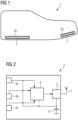
- FIG 1 a shoe 1 with two command transmission devices 2 according to an embodiment of the invention is shown.
- the command transmission devices 2 are designed as wireless shoe sensors and are each integrated into a shoe sole by fixing units 2a, which surround the command transmission devices 2.
- a movement of the shoe 1 is detected by a command transmission device 2 by sensors (see FIG 2 ) is recorded and evaluated. Based on the evaluation, a command is generated which is transmitted to a medical device so that a control, in particular switching a medical device on or off, can be carried out remotely without the operator having to approach the medical device or use their hands for a switching process.
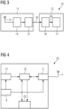
- the command transmission device 2 comprises a plurality of sensors 3a, 3b, 3c, which detect a movement or other physical information.
- the sensors 3a, 3b, 3c can, for example, each comprise a pressure sensor, which measures an electrical voltage change in response to an external mechanical force.
- the sensor signals generated are transmitted to an evaluation unit 4, for example a microcontroller 4, with ultra-low energy consumption, which is also part of the command transmission device 2.
- the microcontroller 4 generates a command signal based on the sensor signals.
- the command transmission device 2 also comprises a transmitting-receiving unit, in the simplest case an RF transmitter 5, and an antenna 7 for transmitting a command signal generated on the basis of an expression of will of an operator determined by the evaluation unit 4.
- the transmitting/receiving unit 5 can also be used as an interface for receiving additional external sensor signals that are transmitted from external units to the command transmission device 2.
- an external acoustic sensor unit and an external image data acquisition unit can record information about vocalizations and movements or changes in posture of an operator and transmit it to the command transmission device 2.
- the acoustic data and the image data can then be evaluated by the evaluation unit 4 in addition to the sensor data recorded by the internal sensors 3a, 3b, 3c in order to determine an expression of will of an operator.
- the command transmission device 2 further comprises an internal electronic energy generation and energy storage unit 6.
- the energy generation and energy storage unit 6 comprises a piezoceramic element with which When mechanical force is applied to the element mentioned, electrical energy is generated and can be stored. For example, a movement of a shoe, a leg or an arm can be used to generate electrical energy as part of a so-called energy harvesting process. This is then stored in an electrical energy storage device, for example a capacitor or an accumulator, and used to supply the microcontroller 4 or the evaluation unit 4, the transmitter 5 and the sensors 3a, 3b, 3c with electrical energy.
- an electrical energy storage device for example a capacitor or an accumulator
- FIG 3 A permanently installed receiving device 10 of a command transmission system according to an embodiment of the invention is illustrated.
- a command transmission system 50 includes the FIG 2 shown command transmission device 2 and the in FIG 3
- the permanently installed receiving device 10 is, for example, attached to a medical device, such as the one shown in FIG 5 shown CT system 50.
- the permanently installed receiving device 10 comprises a wireless receiving unit 11 and an actuator system 12.
- the wireless receiving unit 11 comprises an antenna 13 and a receiver 14, for example an RF receiver, for receiving a command signal from a command transmission device 2 installed on a shoe 1.
- the wireless receiving unit 11 also comprises a microcontroller 15, which is set up to evaluate a command signal received from the wireless receiving unit 11. Based on the command signal, an initialization command IB is given to the actuator system 12.
- the actuator system 12 comprises a system microcontroller 16 and an actuator 17.
- the system microcontroller 16 receives the initialization command IB and transmits a control command to an actuator or a switch that is actuated to start operation of a medical imaging device
- FIG 4 is a schematic representation of a gesture shoe sensor 20 according to an embodiment of the invention.
- the gesture shoe sensor 20 comprises an inertial sensor system 21 with which an acceleration, a rotation or a magnetic field can be measured.
- a sensor system can, for example, comprise components in which so-called MEMS are integrated in ICs and which offer a serial interface to a microcontroller.
- the recorded sensor signals are transmitted from the inertial sensor system 21 to a microcontroller 22, which consumes particularly little energy.
- the microcontroller 22 generates a gesture command signal based on the sensor signal generated by the inertial sensor system 21 and transmits the gesture command signal to a transceiver unit 5, which is also part of the gesture search sensor 20.
- the transmitting-receiving unit 5 generates an initialization command signal, which is transmitted to a permanently installed receiving device using an antenna 7.
- Part of the gesture shoe sensor 20 is also a power supply 6, which is, for example, in the FIG 2 shown.
- the gesture shoe sensor 20 also includes a unit 25 for transmitting haptic feedback to an operator. If the operator gives an initialization command using a gesture, the inertial sensor 21 detects the movement and transmits the detected sensor signal to the microcontroller 22.
- the microcontroller 22 evaluates the sensor signal and, if it detects a gesture that identifies an initialization command, it outputs a corresponding command signal to the transmitting-receiving unit 5 and additionally transmits a control signal to the unit 25 for transmitting haptic feedback.
- the unit 25 for transmitting haptic feedback then generates a mechanical signal, for example a vibration movement, with which the operator or the wearer of the gesture shoe sensor 20 is informed that the command generated by him or her using a gesture has been recognized and passed on.
- a mechanical signal for example a vibration movement
- the operator can then switch on and adjust an X-ray tube using another gesture, for example a hand movement or an eye or head movement.
- the gesture mentioned is recorded, for example, by an image recording unit and received and evaluated by a permanently installed receiving unit arranged on the medical imaging device. Control processes can advantageously be made more reliable by a control gesture with the help of a gesture shoe sensor 20, so that no control can be carried out accidentally, which could harm a patient.
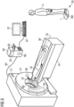
- FIG 5 shows a computer tomography system 50 according to an embodiment of the invention.
- the computer tomograph shown here has a recording unit 57, comprising a radiation source 58 in the form of an X-ray source and a radiation detector 59 in the form of an X-ray detector.
- the recording unit 57 rotates about a system axis 55 during the recording of X-ray projections, and the X-ray source 58 emits rays 52 in the form of X-rays during the recording.
- the X-ray source 58 is an X-ray tube.
- the X-ray detector 59 is a line detector with several lines.
- a patient 53 lies on a patient couch 56 when recording projections.
- the patient couch 56 is connected to a couch base 54 in such a way that it supports the patient couch 56 with the patient 53.
- the patient couch 56 is designed to move the patient 53 along a recording direction through the opening 60 of the recording unit 57.
- the recording direction is usually given by the system axis 55, which is aligned in the z-direction.
- the recording unit 57 rotates around the z-axis when recording X-ray projections.
- the patient's body axis is the same as the system axis 55. Both axes are on the Z-axis of a three-dimensional, Cartesian coordinate system.
- the patient bed 56 is continuously moved through the opening 60, while the recording unit 67 rotates around the patient 53 and records X-ray projections.
- the X-rays thus describe a spiral on the surface of the patient 53.
- the X-ray image recording device 51 has a computer 62, which is connected to a display unit 61, for example for the graphic display of X-ray images, and an input unit 67.
- the display unit 61 can be an LCD, plasma or OLED screen, for example. It can also be a touch-sensitive screen, which is also designed as an input unit 67. Such a touch-sensitive screen can be integrated into the imaging device or designed as part of a mobile device.
- the input unit 67 is, for example, a keyboard, a mouse, a so-called "touch screen" or a microphone for voice input.
- the input unit 67 can also be set up to recognize movements of a user and translate them into corresponding commands. Using the input unit 67, a selected reference data set can be modified by a user, for example.
- the computer 62 is connected to the rotatable recording unit 57 for data exchange.
- control signals for the X-ray image recording are transmitted from the computer 62 to the recording unit 57 via the connection 64, and on the other hand, recorded projection data are transmitted to the computer 62 for image reconstruction.
- the connection 64 is implemented in a known manner, either wired or wirelessly.
- the computer 62 has a computing unit 66.
- the computing unit 66 is designed as an image or image data processing unit It is designed to carry out data processing steps related to the method according to the invention.
- the computing unit 66 can interact with a computer-readable data carrier 63, in particular to receive and process commands using a computer program with program code and to control imaging.
- the computer program can be stored on the machine-readable carrier in a retrievable manner.
- the machine-readable carrier can be a CD, DVD, Blu-ray disc, a memory stick or a hard disk.
- the computing unit 66 can be designed in the form of hardware or in the form of software.
- the computing unit 66 is designed as a so-called FPGA (acronym for the English "Field Programmable Gate Array”) or comprises an arithmetic logic unit.
- FIG 5 is also a command transmission system 70 (see in detail in FIG 7 ) with a transmitting unit 2M and a receiving unit 2S.
- the receiving unit 2S is designed as a radio interface part of the computer 62 slave circuit.
- the transmitting unit 2M is integrated into a shoe 1 of an operator P and designed as a master circuit.
- the operator P can now activate a voice recognition function of the receiving unit 2S designed as a slave circuit by means of a movement sequence of the shoe 1.
- the operator P then gives a voice command which is received and interpreted by the receiving unit 2S.
- the receiving unit 2S On the basis of this interpretation, the receiving unit 2S generates a command to carry out a function, such as browsing through images or changing a contrast.
- the receiving unit 2S can also control a switch 12 which functions as an actuator.
- the switch 12 is used, for example, to trigger the radiation by the radiation source 58.
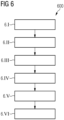
- FIG 6 A flow chart 600 is shown which illustrates a command transmission method according to an embodiment of the invention.
- step 6.1 a detection of a movement of an operator P by a first command transmission device 2M arranged on the operator P.
- a first command transmission device 2M arranged on the operator P.
- an experienced radiologist who is currently examining a patient with his hands is standing next to a mobile C-arm device. Due to the simultaneous examination with his hands, the radiologist currently has no hands free to operate the C-arm device for imaging the patient P. The radiologist therefore wears a FIG 1 and FIG 2 described first command transmission device 2M in one of its shoes 1 or both shoes 1.
- the first command transmission device 2M is initialized in a so-called master mode, ie in this master mode only the electronic sensor for motion detection is activated, but the voice recognition is deactivated, since the first command transmission device 2M in this embodiment is only used to activate a voice recognition of an identical second command transmission device 2M, which is arranged on the C-arm device.
- step 6.II the recorded movement of the operator, i.e. in this specific embodiment the radiologist, is evaluated and a command is identified based on the recorded movement.
- the movement of the operator P can, for example, comprise a foot tap sequence of three foot tap movements.
- the command is an activation command with which the second command transmission device 2S is switched to be ready to receive a voice command from the radiologist.
- the identified command is then transmitted wirelessly to the second command transmission device 2S, which is arranged on the medical device to be operated, in this case a C-arm device.
- step 6.IV the voice recognition of the second command transmission device 2S is then activated.
- step 6.V the second command transmission device 2S records a voice command given by the radiologist and evaluates it using the internal voice recognition. For example, the word “turn the page” or “image back” or “image forward” is recognized.
- This command is interpreted by the second command transmission device 2S as a command to turn the page between several image data sets, but only if the gesture command described in step 6.II was given and recognized, and in step 6.VI a corresponding control command is transmitted wirelessly or by cable to an image display unit of a C-arm device, which is used to switch back and forth between different image data sets. This two-stage procedure can prevent an action from being triggered unintentionally.
- FIG 7 A command transmission system 70 according to an embodiment of the invention is shown schematically. Such a command transmission system 70 is used, for example, in the FIG 5 System 50 shown in Figure 5 is used.
- the FIG 7 The command transmission system 70 shown comprises a transmitting unit 2M fixed to the clothing of an operator P, for example a shoe, and a receiving unit 2S mounted on a medical imaging system (not shown).
- the structure of the transmitting unit 2M largely corresponds to that in FIG 2 shown structure of the command transmission device 2 illustrated there.
- the transmitting unit 2M also has an energy generation and storage unit 6 in the form of an energy harvesting unit, with which the movement of the operator P can be converted into electrical energy and this can also be stored.
- the FIG 7 shown transmitting unit 2M has a speech recognition unit 4a, with which acoustic sensor signals, which were recorded for example by an external acoustic sensor unit and are transmitted to the speech recognition unit 4a via the transmitting-receiving unit 5, can be examined for content information, ie for words and parts of sentences.
- the transmitting unit 2M is designed as a master unit and is used to initialize a two-stage command sequence with which a safety-critical control of a medical device can be carried out in a secure manner. Therefore, the speech recognition unit 4a in the transmitter unit 2M installed as the master unit is not required and is therefore not activated.
- a component 2S that is largely constructed in the same way as the transmitter unit 2S can advantageously be used as the receiver unit 2S, in which the described function for evaluating acoustic information and for speech recognition is used.
- the receiver unit 2S differs from that in the transmitter unit 2M in that its energy supply 6a is not based on movement utilization, since the receiver unit 2S is permanently arranged on a medical device and thus cannot use kinetic energy to generate electrical energy.
- the energy supply 6a mounted on the receiver unit 2S can, for example, comprise a battery unit or a mains connection.
- the receiving unit 2S is also connected to an actuator unit 12 via a data transmission line.
- the actuator unit 12 comprises a system microcontroller 16 and, for example, a switch arrangement 17 with which a function of the medical device can be triggered.
- the functionality of the FIG 7 The functionality of the FIG 7
- the function of the command transmission system 70 shown is as follows: If the operator P wants to trigger a function of the medical device, he first moves his foot in a predetermined manner. For example, he taps once with the heel, once with the tip of the foot and once again with the heel.
- the sensor signals of the pressure sensors 3a, 3b, 3c of the transmitting unit 2M triggered by these movements are transmitted to the evaluation unit 4 of the transmitting unit 2M.
- the evaluation unit 4 of the transmitting unit 2M now recognizes on the basis of the recorded sensor signals that the voice recognition 4a of the receiving unit 2S should be activated. Therefore, an initialization command IB is sent to the radio unit 5 of the receiving unit 2S.
- the receiving unit 2S evaluates the received initialization command IB through its evaluation unit 4 and activates its voice recognition unit 4a because it now expects a voice command ASB next.
- the operator P then gives a voice command ASB, for example he wants to trigger radiation from the medical device with the words "energy on”.
- the voice command ASB is now recorded by an acoustic sensor unit 71, which is part of the receiving unit 2M, for example a microphone, and transmitted to the voice recognition unit 4a of the evaluation unit 4 of the receiving unit 2S.
- the voice recognition unit 4a of the receiving unit 2S now determines the content of the voice command ASB given by the operator P. In this case, it is determined that radiation should be triggered.
- a control command SB is therefore transmitted to the actuator unit 12 via the data transmission unit 5 to trigger radiation.
- the safety-critical radiation release is therefore only carried out when two independent commands generated in different ways are given in quick succession, so that the radiation can be avoided from being switched on accidentally.
- FIG 8 a command transmission system 80 according to an alternative embodiment of the invention is shown.
- the FIG 8 The command transmission system 80 shown also comprises, like the one in FIG 7
- the command transmission system 70 shown has a transmitting unit 20a and a receiving unit 20b.
- the transmitting unit 20a is designed as a master unit, ie the transmitting unit 20a serves to control command detection by the receiving unit 20b designed as a slave unit.
- the transmitting unit 20a used in the command transmission system 80 shown is structurally similar to FIG 4
- the gesture shoe sensor 20 shown in FIG 8 The transmission unit 20a shown has an inertial sensor 21 with which a gesture, ie a movement of a Shoe can be detected by measuring acceleration and measuring a rotational movement.
- the transmitting unit 20a comprises a plurality of different sensors 3a, 3b, 3c, 21 in order to be able to react flexibly to different types of input, as well as an evaluation unit 4 for evaluating sensor signals and for assigning command contents to recognized movements, voice commands or visually recognizable postures or gestures of an operator.
- the transmitting unit 20a has pressure sensor units 3a, 3b, 3c with which a weight shift of the foot, for example to the tip of the foot or the heel of the foot, can be detected.
- the transmitting unit 20a comprises, as already mentioned, an inertial sensor unit 21 with which accelerated movements of a shoe can be detected.
- the transmitting unit 20a also comprises a speech recognition unit 4a, which is part of the evaluation unit 4, with which voice commands can be recognized on the basis of acoustic measurement data. Acoustic measurement data can be received, for example, via the transmitting/receiving unit 5 from an acoustic sensor 71, for example a microphone, and evaluated by the speech recognition unit 4a.
- the transmission unit 20a shown has an image analysis unit 4b, which is part of the evaluation unit 4, for recognizing gestures of the operator in image data which are captured, for example, by an external video camera 81 and subsequently evaluated by the image analysis unit 4b of the transmission unit 20a.
- FIG 8 The transmitter unit 20a shown as well as the one in FIG 4
- the shoe sensor 20 shown has a unit 25 for transmitting haptic feedback. If an operator P moves his shoe or otherwise performs a movement that can be detected by one of the sensors described in order to activate a gesture or speech recognition function of the receiving unit 20b, the sensor signals are evaluated by the evaluation unit 4 of the transmitting unit 20a and information associated with these signals is determined.
- the evaluation unit 4 of the transmitting unit 20a detects a gesture or a voice command that identifies an initialization command IB, it outputs a corresponding command signal to the transmitting/receiving unit 5 and additionally transmits a control signal HS to the unit 25 for transmitting haptic feedback.
- the unit 25 for transmitting haptic feedback then generates a mechanical signal, for example a vibration movement VB, with which the operator P or the wearer of the gesture shoe sensor is informed that the command IB generated by him or her through a gesture and/or a voice command has been recognized and passed on.
- the command IB is then used to enable, for example, an input for a medical imaging device.
- the operator P can then trigger a function of a medical imaging device through another gesture, for example through a hand movement or an eye or head movement, or a voice command or a combination thereof.
- an initialization command IB is determined with which a visual gesture recognition 4b and a voice recognition 4a of the evaluation unit 4 of the receiving unit 20b are to be activated.
- the receiving unit 20b which is essentially constructed in the same way as the transmitting unit 20a, has received the initialization command IB via its transmitting-receiving unit 5 and has activated its voice recognition unit 4a and its image analysis unit 4b, the operator P can perform a gesture, for example a head movement KB, and at the same time issue a voice command ASB.
- the head movement KB is recorded by an external camera 81 and transmitted to the transmitting-receiving unit 5 of the receiving unit 20b.
- the voice command is recorded by a microphone integrated in the receiving unit 20b and transmitted to the voice recognition unit 4a of the receiving unit 20b.
- the microcontroller 4 of the transmitting unit 20a also evaluates sensor signals from the sensors 3a, 3b, 3c and, if it detects a gesture that indicates an initialization command IB, it outputs a corresponding command signal to the transmitting/receiving unit 5 and additionally transmits a control signal HS to the unit 25 for transmitting haptic feedback.
- the unit 25 for transmitting haptic feedback then generates a mechanical signal, for example a vibration movement VB, with which the operator or the wearer of the gesture shoe sensor 20a is informed that the command generated by him or her through a gesture has been recognized and passed on.
- the command is then used to enable, for example, an input for a medical imaging device.
- the operator can then switch on and adjust an X-ray tube using another gesture, for example a hand movement or an eye or head movement and possibly a simultaneous voice command.
- the receiving unit 20b is constructed analogously to the transmitting unit 20a, but lacks a plurality of different sensors 3a, 3b, 3c, 21, since these are not required for the receiving function.
- the receiving unit 20a also comprises a speech recognition unit 4a, with which, for example, voice commands from a microphone 71 can be received or recorded and evaluated.
- the FIG 8 shown receiving unit 20b also has an image analysis unit 4b for evaluating image data from an external optical sensor unit, for example a video camera 81. With the video camera 81, for example, gestures of the operator P can be recorded and then evaluated by the evaluation unit 4 or the image analysis unit 4b of the receiving unit 20b.
- the actuator unit comprises a system microcontroller 16 and, for example, a switch arrangement 17 with which a function of the medical device can be triggered.
Landscapes
- Engineering & Computer Science (AREA)
- Health & Medical Sciences (AREA)
- Life Sciences & Earth Sciences (AREA)
- Medical Informatics (AREA)
- Physics & Mathematics (AREA)
- General Health & Medical Sciences (AREA)
- Public Health (AREA)
- Veterinary Medicine (AREA)
- Animal Behavior & Ethology (AREA)
- Biophysics (AREA)
- Pathology (AREA)
- Biomedical Technology (AREA)
- Heart & Thoracic Surgery (AREA)
- Molecular Biology (AREA)
- Surgery (AREA)
- Theoretical Computer Science (AREA)
- Nuclear Medicine, Radiotherapy & Molecular Imaging (AREA)
- Radiology & Medical Imaging (AREA)
- General Engineering & Computer Science (AREA)
- Human Computer Interaction (AREA)
- High Energy & Nuclear Physics (AREA)
- Optics & Photonics (AREA)
- General Physics & Mathematics (AREA)
- Microelectronics & Electronic Packaging (AREA)
- Audiology, Speech & Language Pathology (AREA)
- Multimedia (AREA)
- Epidemiology (AREA)
- Primary Health Care (AREA)
- User Interface Of Digital Computer (AREA)
- Manipulator (AREA)
Claims (17)
- Système (70, 80) de transmission d'instructions, comportant- un premier dispositif (2M, 20a) de transmission d'instructions, qui a- une unité (3a, 3b, 3c, 21, 71, 81) de capteur pour la détection d'un mouvement d'une personne (P) de service,- une unité (2a) de fixation pour la fixation de l'unité (3a, 3b, 3c, 21, 71, 81) de capteur et/ou du dispositif de transmission d'instructions sur la personne (P) de service,- une unité (4, 4a, 4b, 15, 22) d'évaluation pour l'évaluation du mouvement détecté de la personne (P) de service et pour l'identification d'une instruction (IB, ASB, KB) sur la base du mouvement détecté, et- une unité de transmission d'instructions pour la transmission d'une instruction de commande sur la base de l'instruction (IB, ASB, KB) identifiée à un dispositif (50) de la technique médicale à desservir,dans lequel l'unité (3a, 3b, 3c, 21) de capteur comprend une unité interne de capteur de gestes pour une reconnaissance de gestes,- est constitué en dispositif maître pour un échange bidirectionnel avec au moins un dispositif esclave,- dont l'unité (3a, 3b, 3c, 21) de capteur de gestes est activée et- est agencée pour transmettre une instruction (IB) déterminée à un deuxième dispositif (2S, 20b) de transmission d'instructions,- le deuxième dispositif (2S, 20b) de transmission d'instructions, qui- est monté en étant loin de la personne (P) de service, de préférence sur un dispositif (50) de la technique médicale à desservir,- est constitué en dispositif esclave pour un échange de données bidirectionnel avec un dispositif maître,- a une unité (4) d'évaluation, qui comprend au moins l'une des sous-unités suivantes :- une unité (4b) de reconnaissance de gestes, qui est activée à distance d'une personne (P) de service pour la détection d'un mouvement ou d'un geste de la personne (P) de service,- une unité (4a) de reconnaissance vocale ayant une aptitude à la reconnaissance vocale, et- est agencé pour recevoir l'instruction (IB) reçue du premier dispositif (2M, 20a) de transmission d'instructions et pour transmettre, sur la base de l'instruction (IB) reçue, une instruction (SB) de commande au dispositif (50) de la technique médicale.
- Système de transmission d'instructions suivant la revendication 1, dans lequel la reconnaissance de gestes du premier dispositif de transmission d'instructions s'effectue par détection d'un mouvement de l'unité (3a, 3b, 3c, 21) de capteur ou d'une action mécanique sur l'unité (3a) de capteur.
- Système de transmission d'instructions suivant la revendication 1 ou 2, dans lequel l'unité (2a) de fixation du premier dispositif de transmission d'instructions est constituée pour fixer l'unité (3a, 3b, 3c, 21) de capteur de gestes sur ou dans une pièce de vêtement, de préférence dans une chaussure (1).
- Système de transmission d'instructions suivant la revendication 3, dans lequel l'unité (2a) de fixation du premier dispositif de transmission d'instructions est constituée sous la forme d'un évidement dans la semelle de la chaussure (1).
- Système de transmission d'instructions suivant l'une des revendications précédentes, dans lequel l'unité de transmission d'instructions du premier dispositif de transmission d'instructions a une unité de transfert radio pour la transmission de l'instruction (IB) identifiée au dispositif (50) de la technique médicale à desservir.
- Système de transmission d'instructions suivant l'une des revendications précédentes, dans lequel le premier dispositif de transmission d'instructions a en outre une unité (6) de production et d'accumulation d'énergie, laquelle est agencée de préférence pour produire de l'énergie électrique à partir de l'énergie cinétique de la personne (P) de service.
- Système de transmission d'instructions suivant l'une des revendications précédentes, dans lequel- l'unité (71) de capteur du premier dispositif de transmission d'instructions comprend une unité de capteur acoustique et- son unité (4, 15, 22) d'évaluation comprend une unité (4a) de reconnaissance vocale pour la reconnaissance et l'interprétation d'instructions vocales de la personne (P) de service.
- Système de transmission d'instructions suivant l'une des revendications précédentes, dans lequel la reconnaissance interne de gestes du premier dispositif de transmission d'instructions reconnaît l'une des instructions fonctionnelles suivantes :- défilement d'images sur un affichage d'image d'un appareil (50) de la technique médicale,- modification de paramètres d'un appareil (50) de la technique médicale.
- Système (2, 10, 20) de transmission d'instructions suivant l'une des revendications précédentes, dans lequel- le premier dispositif (2, 2M, 20a) de transmission d'instructions est agencé- pour identifier un geste qui initialise une instruction (ASB) vocale,- sur la base du geste identifié, pour initialiser une mise en fonctionnement du deuxième dispositif (2S, 20b) de transmission d'instructions,- le deuxième dispositif (2S, 20b) de transmission d'instructions est agencé- pour recevoir une instruction (IB) d'initialisation du premier dispositif (2M, 20a) de transmission d'instructions,- pour activer l'unité (4a) de reconnaissance vocale et/ou l'unité (4b) de reconnaissance de gestes sur la base de l'instruction (IB) d'initialisation.
- Système (70, 80) de transmission d'instructions suivant la revendication 9, dans lequel le deuxième dispositif (2M, 20b) de transmission d'instructions est agencé pour détecter par la personne (P) de service et pour identifier, après activation de l'unité (4a) de reconnaissance vocale, une instruction (ASB) vocale et pour transmettre, sur la base de l'instruction (ASB) vocale identifiée, une instruction (SB) de commande au dispositif (50) de la technique médicale.
- Système de transmission d'instructions suivant l'une des revendications précédentes, dans lequel l'unité (4b) de reconnaissance de gestes ou l'unité (4a) de reconnaissance vocale comprend une aptitude à reconnaître des signaux d'actionnement suivants :- un déclenchement de rayonnement,- des mouvements de l'appareil (50) de la technique médicale.
- Système de transmission d'instructions suivant l'une des revendications précédentes, dans lequel l'unité (4b) de reconnaissance de gestes est constituée pour détecter l'un des gestes suivants :- préhension, relâchement, zoom, déplacement de mains ou de doigts,- clignotement des yeux se déplaçant vers la gauche, la droite, le haut, le bas,- mouvement de tête vers la gauche ou vers la droite.
- Système de transmission d'instructions suivant l'une des revendications précédentes, dans lequel le premier dispositif (2M, 20a) de transmission d'instructions est agencé pour transmettre un message en retour haptique à la personne (P) de service en réponse à une instruction détectée.
- Système opérationnel, comportant,- un dispositif (50) d'imagerie de la technique médicale,- un dispositif opérationnel,un système (70, 80) de transmission d'instructions suivant l'une des revendications précédentes, agencé pour la transmission d'une instruction (SB) de commande au dispositif (50) d'imagerie de la technique médicale.
- Procédé de transmission d'instructions, comportant les stades :- détection d'un mouvement d'une personne de service au moyen d'une unité de capteur d'un premier dispositif de transmission d'instructions, dans lequel l'unité de capteur et/ou le premier dispositif de transmission d'instructions est fixé à la personne de service au moyen d'une unité de fixation,- évaluation, au moyen d'une unité d'évaluation du premier dispositif de transmission d'instructions, du mouvement détecté de la personne de service et identification d'une instruction sur la base du mouvement détecté,- transmission à un dispositif de la technique médicale à desservir, au moyen d'une unité de transmission d'instructions du premier dispositif de transmission d'instructions, d'une instruction de commande sur la base de l'instruction identifiée,dans lequel∘ l'unité de capteur comprend une unité interne et activée de capteur de gestes pour une reconnaissance de gestes,∘ le premier dispositif de transmission d'instructions• est constitué en dispositif maître pour un échange bidirectionnel avec au moins un dispositif esclave et est agencé pour transmettre une instruction déterminée à un deuxième dispositif de transmission d'instructions,∘ le deuxième dispositif de transmission d'instructions• est monté à distance de la personne de service, de préférence sur un dispositif de la technique médicale à desservir,• est constitué en dispositif esclave pour un échange de données bidirectionnel avec le dispositif maître,• a une unité d'évaluation, qui comprend au moins l'une des sous-unités suivantes :et▪ une unité (4b) de reconnaissance de gestes, qui est activée à distance d'une personne (P) de service pour la détection d'un mouvement ou d'un geste de la personne (P) de service, et▪ une unité (4a) de reconnaissance vocale ayant une aptitude à la reconnaissance vocale,- réception au moyen du deuxième dispositif de transmission d'instructions de l'instruction transmise par le premier dispositif de transmission d'instructions et- transmission, sur la base de l'instruction reçue, d'une instruction de commande au dispositif médical.
- Produit de programme d'ordinateur comprenant un programme d'ordinateur, qui est mis en mémoire directement dans un dispositif de mémoire d'un système (70, 80) de transmission d'instructions, comprenant des parties de programme pour exécuter tous les stades du procédé suivant la revendication 15, lorsque le programme d'ordinateur est exécuté dans le système (70, 80) de transmission d'instructions.
- Support déchiffrable par ordinateur, sur lequel sont mises en mémoire des parties de programme déchiffrables et exécutables par une unité informatique, afin d'exécuter tous les stades du procédé suivant la revendication 15, lorsque les parties de programme sont exécutées par l'unité informatique.
Priority Applications (3)
| Application Number | Priority Date | Filing Date | Title |
|---|---|---|---|
| EP20201566.5A EP3984458B1 (fr) | 2020-10-13 | 2020-10-13 | Commande simultanée basée sur les gestes pour un dispositif technique médical |
| US17/494,268 US12510970B2 (en) | 2020-10-13 | 2021-10-05 | Simultaneous gesture-based actuation of a medical facility |
| CN202111190877.8A CN114360704B (zh) | 2020-10-13 | 2021-10-13 | 指令传输装置、指令传输系统、手术系统和指令传输方法 |
Applications Claiming Priority (1)
| Application Number | Priority Date | Filing Date | Title |
|---|---|---|---|
| EP20201566.5A EP3984458B1 (fr) | 2020-10-13 | 2020-10-13 | Commande simultanée basée sur les gestes pour un dispositif technique médical |
Publications (2)
| Publication Number | Publication Date |
|---|---|
| EP3984458A1 EP3984458A1 (fr) | 2022-04-20 |
| EP3984458B1 true EP3984458B1 (fr) | 2025-01-15 |
Family
ID=72852481
Family Applications (1)
| Application Number | Title | Priority Date | Filing Date |
|---|---|---|---|
| EP20201566.5A Active EP3984458B1 (fr) | 2020-10-13 | 2020-10-13 | Commande simultanée basée sur les gestes pour un dispositif technique médical |
Country Status (3)
| Country | Link |
|---|---|
| US (1) | US12510970B2 (fr) |
| EP (1) | EP3984458B1 (fr) |
| CN (1) | CN114360704B (fr) |
Families Citing this family (6)
| Publication number | Priority date | Publication date | Assignee | Title |
|---|---|---|---|---|
| EP4356223A1 (fr) * | 2021-06-16 | 2024-04-24 | Qualcomm Incorporated | Activation d'une interface gestuelle destinée à des assistants vocaux à l'aide d'une détection radiofréquence (re) |
| JP2023028949A (ja) * | 2021-08-20 | 2023-03-03 | キヤノンメディカルシステムズ株式会社 | X線撮影装置、x線撮影システム、及びx線撮影装置の制御方法 |
| EP4446867A1 (fr) * | 2023-04-13 | 2024-10-16 | Koninklijke Philips N.V. | Système de commande et procédé de commande d'équipement |
| WO2025024706A1 (fr) * | 2023-07-26 | 2025-01-30 | University Of Rochester | Dispositif, système et procédé de commande de pied pour commande d'instrument chirurgical |
| EP4517488A1 (fr) | 2023-08-28 | 2025-03-05 | Koninklijke Philips N.V. | Système et procédé de commande gestuelle d'un dispositif d'imagerie médicale |
| DE102024118747A1 (de) * | 2024-07-02 | 2026-01-08 | Bayerische Motoren Werke Aktiengesellschaft | Vorrichtung zur Bedienung einer Mensch-Maschine-Schnittstelle |
Family Cites Families (21)
| Publication number | Priority date | Publication date | Assignee | Title |
|---|---|---|---|---|
| US6773349B2 (en) | 2002-07-31 | 2004-08-10 | Intec, Inc. | Video game controller with integrated video display |
| WO2005114524A2 (fr) | 2004-05-19 | 2005-12-01 | Sensitron, Inc. | Systemes et procedes de surveillance de patient a distance personnalises |
| US9002680B2 (en) * | 2008-06-13 | 2015-04-07 | Nike, Inc. | Foot gestures for computer input and interface control |
| DE102008040502A1 (de) | 2008-07-17 | 2010-01-21 | Biotronik Crm Patent Ag | Medizinisches Implantat mit mindestens zwei Datenkommunikationskanälen |
| US9439736B2 (en) | 2009-07-22 | 2016-09-13 | St. Jude Medical, Atrial Fibrillation Division, Inc. | System and method for controlling a remote medical device guidance system in three-dimensions using gestures |
| GB2474536B (en) * | 2009-10-13 | 2011-11-02 | Pointgrab Ltd | Computer vision gesture based control of a device |
| CN102906671B (zh) * | 2010-07-20 | 2016-03-02 | 松下电器(美国)知识产权公司 | 手势输入装置及手势输入方法 |
| US11071344B2 (en) * | 2012-02-22 | 2021-07-27 | Nike, Inc. | Motorized shoe with gesture control |
| US20140266570A1 (en) * | 2013-03-12 | 2014-09-18 | Anirudh Sharma | System and method for haptic based interaction |
| KR101566198B1 (ko) * | 2013-06-28 | 2015-11-05 | 삼성전자주식회사 | 초음파 진단 장치의 디스플레이 이동 방법 및 초음파 진단 장치 |
| US20160299570A1 (en) * | 2013-10-24 | 2016-10-13 | Apple Inc. | Wristband device input using wrist movement |
| WO2016061699A1 (fr) * | 2014-10-23 | 2016-04-28 | Orpyx Medical Technologies Inc. | Dispositif de commande basé sur des mouvements de pied |
| US10613637B2 (en) * | 2015-01-28 | 2020-04-07 | Medtronic, Inc. | Systems and methods for mitigating gesture input error |
| DE102015211965A1 (de) * | 2015-06-26 | 2016-12-29 | Siemens Healthcare Gmbh | Berührungslose Gerätesteuerung im medizinischen Sterilbereich |
| US20170103440A1 (en) * | 2015-08-01 | 2017-04-13 | Zhou Tian Xing | Wearable augmented reality eyeglass communication device including mobile phone and mobile computing via virtual touch screen gesture control and neuron command |
| US10007335B2 (en) * | 2015-12-14 | 2018-06-26 | Empire Technology Development Llc | User interface selection based on user context |
| US20170177088A1 (en) * | 2015-12-21 | 2017-06-22 | Sap Se | Two-step gesture recognition for fine-grain control of wearable applications |
| EP3486915B1 (fr) * | 2017-11-17 | 2023-11-08 | Siemens Healthcare GmbH | Procédé de commande de fonctionnement d'un dispositif technique médicale, appareil de commande, système de commande et dispositif technique médicale |
| EP4016541B1 (fr) | 2018-11-23 | 2025-11-19 | Siemens Healthineers AG | Visualisation d'images médicales intégrées et exploration |
| US11382383B2 (en) * | 2019-02-11 | 2022-07-12 | Brilliant Sole, Inc. | Smart footwear with wireless charging |
| CN110365778B (zh) | 2019-07-17 | 2021-09-07 | 腾讯科技(深圳)有限公司 | 一种通信控制的方法、装置、电子设备和存储介质 |
-
2020
- 2020-10-13 EP EP20201566.5A patent/EP3984458B1/fr active Active
-
2021
- 2021-10-05 US US17/494,268 patent/US12510970B2/en active Active
- 2021-10-13 CN CN202111190877.8A patent/CN114360704B/zh active Active
Also Published As
| Publication number | Publication date |
|---|---|
| US20220113809A1 (en) | 2022-04-14 |
| EP3984458A1 (fr) | 2022-04-20 |
| US12510970B2 (en) | 2025-12-30 |
| CN114360704B (zh) | 2025-02-25 |
| CN114360704A (zh) | 2022-04-15 |
Similar Documents
| Publication | Publication Date | Title |
|---|---|---|
| EP3984458B1 (fr) | Commande simultanée basée sur les gestes pour un dispositif technique médical | |
| DE102013226244B4 (de) | Medizintechnische Steuerung | |
| JP7496776B2 (ja) | 高速、正確及び直観的なユーザ対話のための適合を有する脳-コンピュータインターフェース | |
| CN110099649B (zh) | 具有用于工具致动的虚拟控制面板的机器人外科系统 | |
| EP3229161B1 (fr) | Système comprenant un appareil de commande mobile et procédé d'émission d'un signal de commande sur un composant d'un dispositif d'imagerie médical | |
| DE102013226242A1 (de) | Einstellung eines Aufnahmebereichs | |
| EP3305232B1 (fr) | Dispositif de commande et procede de commande pour l'opération d'un dispositif médical | |
| EP3630422B1 (fr) | Système de manipulation comprenant un moyen de saisie pour la réduction de forces | |
| DE102015211965A1 (de) | Berührungslose Gerätesteuerung im medizinischen Sterilbereich | |
| WO2005016164A1 (fr) | Unite de commande, conçue en particulier pour des appareils techniques medicaux | |
| Esfandiari et al. | Introducing a brain-computer interface to facilitate intraoperative medical imaging control–a feasibility study | |
| Vilimek et al. | BC (eye): Combining eye-gaze input with brain-computer interaction | |
| Kilmarx et al. | Sequence-based manipulation of robotic arm control in brain machine interface | |
| DE102016210329B4 (de) | Mobile Bedienvorrichtung, Bediensystem sowie Verfahren zur Steuerung für ein Medizingerät | |
| Opromolla et al. | A usability study of a gesture recognition system applied during the surgical procedures | |
| Manolova | System for touchless interaction with medical images in surgery using Leap Motion | |
| Poon et al. | A novel user-specific wearable controller for surgical robots | |
| DE102014202433B4 (de) | Abdeckeinheit für eine Geräteeinheit | |
| DE102013215809A1 (de) | Verfahren und Vorrichtungen zur autorisierten Bedienung eines medizinischen bildgebenden Geräts | |
| Fougner | Robust, Coordinated and Proportional Myoelectric Control of Upper-Limb Prostheses | |
| DE102015204767A1 (de) | Bedienung eines Medizingerätes | |
| DE102014208215B3 (de) | Steuerungssystem für ein Röntgengerät sowie Verfahren zur Steuerung eines Röntgengeräts | |
| Seema et al. | Master slave configuration in robotic surgery through image processing | |
| US20240177854A1 (en) | Monitoring remote control suitability | |
| Sivaramakrishnan et al. | A touchless interface for interventional radiology procedures |
Legal Events
| Date | Code | Title | Description |
|---|---|---|---|
| PUAI | Public reference made under article 153(3) epc to a published international application that has entered the european phase |
Free format text: ORIGINAL CODE: 0009012 |
|
| STAA | Information on the status of an ep patent application or granted ep patent |
Free format text: STATUS: THE APPLICATION HAS BEEN PUBLISHED |
|
| AK | Designated contracting states |
Kind code of ref document: A1 Designated state(s): AL AT BE BG CH CY CZ DE DK EE ES FI FR GB GR HR HU IE IS IT LI LT LU LV MC MK MT NL NO PL PT RO RS SE SI SK SM TR |
|
| STAA | Information on the status of an ep patent application or granted ep patent |
Free format text: STATUS: REQUEST FOR EXAMINATION WAS MADE |
|
| 17P | Request for examination filed |
Effective date: 20221017 |
|
| RBV | Designated contracting states (corrected) |
Designated state(s): AL AT BE BG CH CY CZ DE DK EE ES FI FR GB GR HR HU IE IS IT LI LT LU LV MC MK MT NL NO PL PT RO RS SE SI SK SM TR |
|
| STAA | Information on the status of an ep patent application or granted ep patent |
Free format text: STATUS: EXAMINATION IS IN PROGRESS |
|
| 17Q | First examination report despatched |
Effective date: 20231102 |
|
| RAP1 | Party data changed (applicant data changed or rights of an application transferred) |
Owner name: SIEMENS HEALTHINEERS AG |
|
| RIC1 | Information provided on ipc code assigned before grant |
Ipc: A43B 13/00 20060101ALN20240502BHEP Ipc: A43B 3/00 20220101ALN20240502BHEP Ipc: A61B 6/10 20060101ALI20240502BHEP Ipc: A43B 17/00 20060101ALI20240502BHEP Ipc: A43B 3/38 20220101ALI20240502BHEP Ipc: A43B 3/34 20220101ALI20240502BHEP Ipc: A61B 6/46 20240101ALI20240502BHEP Ipc: G06F 3/01 20060101ALI20240502BHEP Ipc: A61B 8/00 20060101ALI20240502BHEP Ipc: A61B 5/00 20060101ALI20240502BHEP Ipc: A61B 6/00 20060101AFI20240502BHEP |
|
| GRAP | Despatch of communication of intention to grant a patent |
Free format text: ORIGINAL CODE: EPIDOSNIGR1 |
|
| STAA | Information on the status of an ep patent application or granted ep patent |
Free format text: STATUS: GRANT OF PATENT IS INTENDED |
|
| RIC1 | Information provided on ipc code assigned before grant |
Ipc: A43B 13/00 20060101ALN20240522BHEP Ipc: A43B 3/00 20220101ALN20240522BHEP Ipc: A61B 6/10 20060101ALI20240522BHEP Ipc: A43B 17/00 20060101ALI20240522BHEP Ipc: A43B 3/38 20220101ALI20240522BHEP Ipc: A43B 3/34 20220101ALI20240522BHEP Ipc: A61B 6/46 20240101ALI20240522BHEP Ipc: G06F 3/01 20060101ALI20240522BHEP Ipc: A61B 8/00 20060101ALI20240522BHEP Ipc: A61B 5/00 20060101ALI20240522BHEP Ipc: A61B 6/00 20060101AFI20240522BHEP |
|
| RIC1 | Information provided on ipc code assigned before grant |
Ipc: A43B 13/00 20060101ALN20240529BHEP Ipc: A43B 3/00 20220101ALN20240529BHEP Ipc: A61B 6/10 20060101ALI20240529BHEP Ipc: A43B 17/00 20060101ALI20240529BHEP Ipc: A43B 3/38 20220101ALI20240529BHEP Ipc: A43B 3/34 20220101ALI20240529BHEP Ipc: A61B 6/46 20240101ALI20240529BHEP Ipc: G06F 3/01 20060101ALI20240529BHEP Ipc: A61B 8/00 20060101ALI20240529BHEP Ipc: A61B 5/00 20060101ALI20240529BHEP Ipc: A61B 6/00 20060101AFI20240529BHEP |
|
| INTG | Intention to grant announced |
Effective date: 20240612 |
|
| GRAJ | Information related to disapproval of communication of intention to grant by the applicant or resumption of examination proceedings by the epo deleted |
Free format text: ORIGINAL CODE: EPIDOSDIGR1 |
|
| STAA | Information on the status of an ep patent application or granted ep patent |
Free format text: STATUS: EXAMINATION IS IN PROGRESS |
|
| INTC | Intention to grant announced (deleted) | ||
| GRAP | Despatch of communication of intention to grant a patent |
Free format text: ORIGINAL CODE: EPIDOSNIGR1 |
|
| STAA | Information on the status of an ep patent application or granted ep patent |
Free format text: STATUS: GRANT OF PATENT IS INTENDED |
|
| RIC1 | Information provided on ipc code assigned before grant |
Ipc: A43B 13/00 20060101ALN20240827BHEP Ipc: A43B 3/00 20220101ALN20240827BHEP Ipc: A61B 6/10 20060101ALI20240827BHEP Ipc: A43B 17/00 20060101ALI20240827BHEP Ipc: A43B 3/38 20220101ALI20240827BHEP Ipc: A43B 3/34 20220101ALI20240827BHEP Ipc: A61B 6/46 20240101ALI20240827BHEP Ipc: G06F 3/01 20060101ALI20240827BHEP Ipc: A61B 8/00 20060101ALI20240827BHEP Ipc: A61B 5/00 20060101ALI20240827BHEP Ipc: A61B 6/00 20060101AFI20240827BHEP |
|
| INTG | Intention to grant announced |
Effective date: 20240918 |
|
| GRAS | Grant fee paid |
Free format text: ORIGINAL CODE: EPIDOSNIGR3 |
|
| GRAA | (expected) grant |
Free format text: ORIGINAL CODE: 0009210 |
|
| STAA | Information on the status of an ep patent application or granted ep patent |
Free format text: STATUS: THE PATENT HAS BEEN GRANTED |
|
| REG | Reference to a national code |
Ref country code: DE Ref legal event code: R081 Ref document number: 502020010197 Country of ref document: DE Owner name: SIEMENS HEALTHINEERS AG, DE Free format text: FORMER OWNER: SIEMENS HEALTHINEERS AG, 91301 FORCHHEIM, DE |
|
| AK | Designated contracting states |
Kind code of ref document: B1 Designated state(s): AL AT BE BG CH CY CZ DE DK EE ES FI FR GB GR HR HU IE IS IT LI LT LU LV MC MK MT NL NO PL PT RO RS SE SI SK SM TR |
|
| REG | Reference to a national code |
Ref country code: CH Ref legal event code: EP Ref country code: GB Ref legal event code: FG4D Free format text: NOT ENGLISH |
|
| REG | Reference to a national code |
Ref country code: DE Ref legal event code: R096 Ref document number: 502020010197 Country of ref document: DE |
|
| REG | Reference to a national code |
Ref country code: IE Ref legal event code: FG4D Free format text: LANGUAGE OF EP DOCUMENT: GERMAN |
|
| REG | Reference to a national code |
Ref country code: NL Ref legal event code: MP Effective date: 20250115 |
|
| PG25 | Lapsed in a contracting state [announced via postgrant information from national office to epo] |
Ref country code: NL Free format text: LAPSE BECAUSE OF FAILURE TO SUBMIT A TRANSLATION OF THE DESCRIPTION OR TO PAY THE FEE WITHIN THE PRESCRIBED TIME-LIMIT Effective date: 20250115 |
|
| PG25 | Lapsed in a contracting state [announced via postgrant information from national office to epo] |
Ref country code: RS Free format text: LAPSE BECAUSE OF FAILURE TO SUBMIT A TRANSLATION OF THE DESCRIPTION OR TO PAY THE FEE WITHIN THE PRESCRIBED TIME-LIMIT Effective date: 20250415 |
|
| PG25 | Lapsed in a contracting state [announced via postgrant information from national office to epo] |
Ref country code: FI Free format text: LAPSE BECAUSE OF FAILURE TO SUBMIT A TRANSLATION OF THE DESCRIPTION OR TO PAY THE FEE WITHIN THE PRESCRIBED TIME-LIMIT Effective date: 20250115 |
|
| PG25 | Lapsed in a contracting state [announced via postgrant information from national office to epo] |
Ref country code: PL Free format text: LAPSE BECAUSE OF FAILURE TO SUBMIT A TRANSLATION OF THE DESCRIPTION OR TO PAY THE FEE WITHIN THE PRESCRIBED TIME-LIMIT Effective date: 20250115 |
|
| PG25 | Lapsed in a contracting state [announced via postgrant information from national office to epo] |
Ref country code: ES Free format text: LAPSE BECAUSE OF FAILURE TO SUBMIT A TRANSLATION OF THE DESCRIPTION OR TO PAY THE FEE WITHIN THE PRESCRIBED TIME-LIMIT Effective date: 20250115 |
|
| REG | Reference to a national code |
Ref country code: LT Ref legal event code: MG9D |
|
| PG25 | Lapsed in a contracting state [announced via postgrant information from national office to epo] |
Ref country code: IS Free format text: LAPSE BECAUSE OF FAILURE TO SUBMIT A TRANSLATION OF THE DESCRIPTION OR TO PAY THE FEE WITHIN THE PRESCRIBED TIME-LIMIT Effective date: 20250515 Ref country code: NO Free format text: LAPSE BECAUSE OF FAILURE TO SUBMIT A TRANSLATION OF THE DESCRIPTION OR TO PAY THE FEE WITHIN THE PRESCRIBED TIME-LIMIT Effective date: 20250415 |
|
| PG25 | Lapsed in a contracting state [announced via postgrant information from national office to epo] |
Ref country code: HR Free format text: LAPSE BECAUSE OF FAILURE TO SUBMIT A TRANSLATION OF THE DESCRIPTION OR TO PAY THE FEE WITHIN THE PRESCRIBED TIME-LIMIT Effective date: 20250115 |
|
| PG25 | Lapsed in a contracting state [announced via postgrant information from national office to epo] |
Ref country code: LV Free format text: LAPSE BECAUSE OF FAILURE TO SUBMIT A TRANSLATION OF THE DESCRIPTION OR TO PAY THE FEE WITHIN THE PRESCRIBED TIME-LIMIT Effective date: 20250115 Ref country code: PT Free format text: LAPSE BECAUSE OF FAILURE TO SUBMIT A TRANSLATION OF THE DESCRIPTION OR TO PAY THE FEE WITHIN THE PRESCRIBED TIME-LIMIT Effective date: 20250515 |
|
| PG25 | Lapsed in a contracting state [announced via postgrant information from national office to epo] |
Ref country code: BG Free format text: LAPSE BECAUSE OF FAILURE TO SUBMIT A TRANSLATION OF THE DESCRIPTION OR TO PAY THE FEE WITHIN THE PRESCRIBED TIME-LIMIT Effective date: 20250115 Ref country code: GR Free format text: LAPSE BECAUSE OF FAILURE TO SUBMIT A TRANSLATION OF THE DESCRIPTION OR TO PAY THE FEE WITHIN THE PRESCRIBED TIME-LIMIT Effective date: 20250416 |
|
| PG25 | Lapsed in a contracting state [announced via postgrant information from national office to epo] |
Ref country code: SE Free format text: LAPSE BECAUSE OF FAILURE TO SUBMIT A TRANSLATION OF THE DESCRIPTION OR TO PAY THE FEE WITHIN THE PRESCRIBED TIME-LIMIT Effective date: 20250115 |
|
| PG25 | Lapsed in a contracting state [announced via postgrant information from national office to epo] |
Ref country code: SM Free format text: LAPSE BECAUSE OF FAILURE TO SUBMIT A TRANSLATION OF THE DESCRIPTION OR TO PAY THE FEE WITHIN THE PRESCRIBED TIME-LIMIT Effective date: 20250115 |
|
| PG25 | Lapsed in a contracting state [announced via postgrant information from national office to epo] |
Ref country code: DK Free format text: LAPSE BECAUSE OF FAILURE TO SUBMIT A TRANSLATION OF THE DESCRIPTION OR TO PAY THE FEE WITHIN THE PRESCRIBED TIME-LIMIT Effective date: 20250115 |
|
| PG25 | Lapsed in a contracting state [announced via postgrant information from national office to epo] |
Ref country code: IT Free format text: LAPSE BECAUSE OF FAILURE TO SUBMIT A TRANSLATION OF THE DESCRIPTION OR TO PAY THE FEE WITHIN THE PRESCRIBED TIME-LIMIT Effective date: 20250115 |
|
| REG | Reference to a national code |
Ref country code: DE Ref legal event code: R097 Ref document number: 502020010197 Country of ref document: DE |
|
| PG25 | Lapsed in a contracting state [announced via postgrant information from national office to epo] |
Ref country code: CZ Free format text: LAPSE BECAUSE OF FAILURE TO SUBMIT A TRANSLATION OF THE DESCRIPTION OR TO PAY THE FEE WITHIN THE PRESCRIBED TIME-LIMIT Effective date: 20250115 Ref country code: EE Free format text: LAPSE BECAUSE OF FAILURE TO SUBMIT A TRANSLATION OF THE DESCRIPTION OR TO PAY THE FEE WITHIN THE PRESCRIBED TIME-LIMIT Effective date: 20250115 |
|
| PG25 | Lapsed in a contracting state [announced via postgrant information from national office to epo] |
Ref country code: RO Free format text: LAPSE BECAUSE OF FAILURE TO SUBMIT A TRANSLATION OF THE DESCRIPTION OR TO PAY THE FEE WITHIN THE PRESCRIBED TIME-LIMIT Effective date: 20250115 |
|
| PG25 | Lapsed in a contracting state [announced via postgrant information from national office to epo] |
Ref country code: SK Free format text: LAPSE BECAUSE OF FAILURE TO SUBMIT A TRANSLATION OF THE DESCRIPTION OR TO PAY THE FEE WITHIN THE PRESCRIBED TIME-LIMIT Effective date: 20250115 |
|
| PLBE | No opposition filed within time limit |
Free format text: ORIGINAL CODE: 0009261 |
|
| STAA | Information on the status of an ep patent application or granted ep patent |
Free format text: STATUS: NO OPPOSITION FILED WITHIN TIME LIMIT |
|
| 26N | No opposition filed |
Effective date: 20251016 |
|
| PGFP | Annual fee paid to national office [announced via postgrant information from national office to epo] |
Ref country code: GB Payment date: 20251111 Year of fee payment: 6 |
|
| PGFP | Annual fee paid to national office [announced via postgrant information from national office to epo] |
Ref country code: FR Payment date: 20251020 Year of fee payment: 6 |
|
| PGFP | Annual fee paid to national office [announced via postgrant information from national office to epo] |
Ref country code: DE Payment date: 20251219 Year of fee payment: 6 |