EP3984812A1 - Élément de rail et système d'alimentation électrique de véhicules routiers - Google Patents
Élément de rail et système d'alimentation électrique de véhicules routiers Download PDFInfo
- Publication number
- EP3984812A1 EP3984812A1 EP20201861.0A EP20201861A EP3984812A1 EP 3984812 A1 EP3984812 A1 EP 3984812A1 EP 20201861 A EP20201861 A EP 20201861A EP 3984812 A1 EP3984812 A1 EP 3984812A1
- Authority
- EP
- European Patent Office
- Prior art keywords
- rail element
- vehicle
- groove
- rail
- road surface
- Prior art date
- Legal status (The legal status is an assumption and is not a legal conclusion. Google has not performed a legal analysis and makes no representation as to the accuracy of the status listed.)
- Granted
Links
Images


Classifications
-
- B—PERFORMING OPERATIONS; TRANSPORTING
- B60—VEHICLES IN GENERAL
- B60M—POWER SUPPLY LINES, AND DEVICES ALONG RAILS, FOR ELECTRICALLY- PROPELLED VEHICLES
- B60M1/00—Power supply lines for contact with collector on vehicle
- B60M1/30—Power rails
- B60M1/34—Power rails in slotted conduits
Definitions
- the invention relates to a rail element adapted to co-act with a current collector of an electrically propellable road vehicle for supplying electric power to said vehicle, the rail element being adapted to extend along a road section on which the vehicle is travelling.
- the invention further relates to a system for supplying electric power to an electrically propellable vehicle, which system comprises such a rail element.
- WO 2011/123046 proposes complementing the battery of the electric vehicle with electric feeding of the vehicle while driving.
- a system is disclosed for electric propulsion of a vehicle along a road comprising rail elements having grooves provided with electric conductors therein that may be put under voltage and located in longitudinal channels in the road.
- the vehicle is equipped with a current collector which during contact with the electric conductors allows for transfer of electric power between the electric conductors and the vehicle to propel the vehicle and charge its battery or set of batteries.
- One problem with the system in this publication is that the rail elements need to have a certain height so that the electric conductors are disposed in the grooves at a safe touching distance from the opening/upper end of the groove.
- installation of the rail elements involves making quite deep channels in the road to recess the rail element, usually by means of routing. In some cases, this means that the channel extends through the whole paving (asphalt, cement or the like) of the road which weakens the road. On certain types of road sections, such as bridges, such deep channels may be particularly disadvantageous or not even possible, in particular at joints of bridge sections.
- An object of the invention is to solve or improve on the problem mentioned above in the background section.
- a rail element adapted to co-act with a current collector of an electrically propellable road vehicle for supplying electric power to said vehicle, the rail element being adapted to extend along a road section on which the vehicle is travelling.
- the rail element is adapted to be located on, or to be partly recessed in, a road surface of said road section, wherein at least one groove is formed at least partly by said rail element at a lateral side thereof with said groove(s) having its opening(s) facing in a respective lateral direction relative a lengthwise direction of the rail element.
- At least one electric conductor is arranged in at least one of the groove(s), said electric conductor(s) extending along the lengthwise direction of said rail element and being adapted to be put under voltage for supplying said electric power.
- the rail element is provided with, or forms at least in part, one or more grooves, where the opening(s) of at least one or all of these grooves face sidewards or laterally, i.e. such that the current collector may enter the groove(s) from the left and/or right side of the rail element (as seen relative the lengthwise direction of the rail element).
- the groove(s) is/are disposed in one or more substantially horizontal planes. At least one of the at least one groove is provided with one or more electric conductors.
- an AC or DC feeding of the electrically propellable vehicle is achieved by means of at least two conductors arranged in respective grooves, or by means of two or more of the at least two conductors being arranged in a common groove. It is also foreseeable that a DC feeding is achieved using a single electric conductor arranged in a single laterally directed groove, whereas a connection to ground is achieved by means of electric contact between the in current collector and an outer/upper surface of the rail element.
- the rail element has an elongated shape, i.e. has a substantially greater length the width and height. It is furthermore understood that the rail element normally extends with its lengthwise direction in parallel with the longitudinal direction of the road section. Thus, the lateral directions of the rail element may coincide with the lateral directions of the road section when arranged thereon.
- the invention is based on the insight that the overall height of the rail element can be substantially reduced by having laterally/sideways directed grooves, i.e. horizontally arranged grooves rather than vertically arranged grooves as in the prior art.
- the grooves may face in the same lateral direction, or in opposite lateral directions.
- two grooves are formed at least partly by said rail element at opposite lateral sides of the rail element with respective openings of the grooves facing in opposite lateral directions relative a lengthwise direction of the rail element, wherein at least one electric conductor is arranged in each of the two grooves.
- two or more grooves are formed at least partly by said rail element, such that at least one groove is formed at each lateral side of the rail element with respective openings of the grooves facing in respective lateral direction, i.e. openings are formed at both lateral sides of the rail element.
- two grooves formed at opposite lateral sides can be disposed in a common horizontal plane.
- the at least one groove is formed in said rail element, i.e. is formed solely by said rail element.
- a rail element is advantageously arranged partly recessed in the road surface such that a lower wall portion of the groove is vertically aligned with the road surface.
- the rail element may comprise parallel upper and lower parts arranged at a distance from each other and being connected to each other with spacing means to form the grooves between said upper and lower parts.
- the upper and lower parts may be formed integrally with the spacing means or may be separate parts which are attached to each other to form the rail element.
- the lower part is advantageously arranged in vertical alignment with the road surface such that water may flow freely in and out of the groove(s).
- the rail element comprises an upper part adapted to be arranged in parallel with the road surface at a distance therefrom, the upper part being adapted to be connected to the road surface via spacing means to form the groove(s) between said upper part and said road surface. Consequently, the groove(s) is/are formed partly by the rail element, and partly by the road surface.
- the upper part and the spacing means are attached to the road surface by means of attachment means, for instance screws, nails or adhesive/glue. Since the road surface defines the lower wall portion of the groove, water may flow freely in and out of the groove(s). This embodiment is advantageous since it can be installed on a road section without making one or more channels in the road surface/paving of the road.
- the spacing means may comprise a plurality of spacing elements arranged spaced apart in the lengthwise direction of the rail element to provide laterally directed through channels in said rail element.
- Such through channels are advantageous since water may flow freely through the rail element from one side to the other to improve drainage.
- the spacing elements may be spaced apart in such a manner that said through channels occupy at least 25%, preferably about 50% of the length of the rail element. Thereby, a large flow area is achieved for improved drainage.
- the upper part of the rail element is made at least partly from a resilient material.
- the resilient material is resilient in the sense that the upper part bends down to make contact with the lower part or road surface when the rail element is run over by a vehicle.
- the upper part is made at least partly from a metallic material such as stainless steel, steel or aluminum.
- the material and the thickness of the upper part is configured such that the upper part does not bend down even when subjected to forces corresponding to the weight of a heavy truck.
- At least one of the conductor(s) is/are arranged in said groove(s) at upper portion(s) thereof.
- the conductor(s) may be attached to the upper part(s) of the rail element.
- Such embodiments are advantageous since the conductor is arranged at a distance from the lower part or road surface which means that it is less exposed to dirt and water flowing in/out of the groove.
- At least one of the conductor(s) is arranged at a lower portion of the corresponding groove(s).
- the conductor(s) may be connected to, or recessed in, the lower part. This may be advantageous since a large cross-sectional area of the conductor(s) may be allowed compared to a position at an upper portion of the groove, where a thick conductor would either inhibit drainage through the rail element and/or weaken the rail element if recessed there into.
- the at least one groove has dimensions corresponding to IEC 60529.
- the groove has a width of equal to or less than 12 mm, and the at least one electric conductor is arranged at least 80 mm below an upper end of the groove. This is advantageous since the electric conductor is effectively protected from accidental touching contact.
- a system for supplying electric power to an electrically propellable vehicle along a road section on which the vehicle is travelling comprising at least one rail element according to the first aspect of the invention, said rail element being placed on, or partly recessed in, a road surface of said road section with its lengthwise direction in parallel with the lengthwise direction of said road section, wherein said at least one rail element is oriented relative the road section such that at least one or each opening of said groove(s) is facing in a respective lateral direction of the road section.
- the rail elements are arranged consecutively.
- the system may furthermore comprise a current collector, or a vehicle with a current collector, wherein the current collector is adapted to co-act with said rail element, wherein the current collector comprises at least one contact element, and wherein the current collector is connected/connectable to said vehicle and is displaceable vertically and laterally relative the vehicle such that the at least one contact element is displaceable into said at least one groove of said rail element to connect mechanically and electrically with one or more corresponding electric conductor(s) of said rail element.
- the rail element is partly recessed in said road surface with an upper surface of the lower part aligned with the road surface. This is advantageous since water may flow freely in and out of the groove(s).
- the current collector comprises cleansing means to clean the groove(s) from particles and loose objects, which cleansing means has a front portion inclined at an acute angle relative the longitudinal direction of the rail element when the current collector is co-acting with the rail element. Put differently, the front portion of the cleansing means is inclined at an acute angle with respect to the bottom part thereof.
- the cleansing means may be a separate cleansing device (as described in applicants' patent EP2994337B1 ), or may be integrally formed with the contact element(s) of the current collector which makes electrical contact with the electric conductor(s) of the rail element.
- the cleansing device may be suspended in a corresponding manner as in applicants' patent EP11763160B1 , which in the present embodiment means that the cleansing device is rotatable around a substantially vertical axis, which axis is resiliently moveable in a horizontal direction away from said rail element.
- EP11763160B1 and EP2994337B1 are hereby incorporated by reference.
- the electric conductors of the rail elements are connected via one or more switches to vehicle-external electric power sources.
- the electric conductors are preferably only connected to the power sources via the switches during time periods or slots when the presence of a vehicle belonging to the system is sensed at the present road section.
- a further electrical security measure is provided in addition to the electrical conductor being protected by means of being arranged in a groove, as described above.
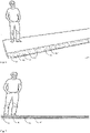
- Fig. 1 shows a rail element 1 being an embodiment of the first aspect of the invention, which is arranged partly recessed in the road surface 4 of a road section 3, thus also illustrating an embodiment of a system according to the second aspect of the invention.
- Two grooves 5a, 5b are formed at in the rail element at opposite lateral sides 6a, 6b of the rail element with respective openings 7a, 7b of the grooves facing in opposite lateral directions L 1 , L 2 relative a lengthwise direction LD of the rail element (see fig. 2 ).
- a U-shaped electric conductor 8a, 8b is arranged at the innermost/bottom part of each groove 5a, 5b.
- the two grooves are disposed in a common horizontal plane.
- the rail element 1 is formed from two identical U-shaped parts connected to each other via a spacing element.
- Fig. 2 shows a cross-section view taken in a horizontal plane through the vertical centre of the rail element in fig. 1 as seen from above. Also shown is a pair of current collector contact elements 2a, 2b being in mechanical and electrical contact with the conductors 8a, 8b. The contact elements extend into the grooves 5a, 5b from respective side of the rail element. The two electric conductors are normally used for AC feeding of electrical power to the vehicle via the current collector.
- the current collector may be provided with a ground contact element which makes contact with the a ground conductor, which may for instance be arranged at an upper/outer surface of the rail element in a corresponding manner as described in applicants' own application SE 1951044-5 .
- the front portions 2a 1 , 2a 2 of the contact elements 2a, 2b are inclined at acute angles with respect to the corresponding bottom part thereof.
- the front portions form cleansing means and act as "plows" to clear the grooves from dirt.
- the contact elements are connected to (not shown) current collector arms which in turn connect to the vehicle, as is known from the applicants' previous patent applications, and further illustrated in another embodiment shown in fig. 8 .
- fig. 2 only shows a lengthwise segment of the rail element - the rail element actually has an elongated shape, i.e. has a substantially greater length in its lengthwise direction LD than width and height. It is further noted that the rail element normally extends at the centre of the road with its lengthwise direction LD in parallel with the longitudinal direction of the road section. Thus, the lateral directions of the rail element coincide with the lateral directions of the road section.
- Fig. 3 shows a cross-section view of another embodiment of a rail element and system according to the invention.
- the rail element 1' is arranged partly recessed in the road surface 4 of a road section 3, and the two grooves 5a', 5b' are formed at in the rail element at opposite lateral sides of the rail element with respective openings of the grooves facing in opposite lateral directions relative a lengthwise direction of the rail element.
- the electric conductors 8a', 8b' are strip-shaped and arranged at an upper portion of the grooves.
- the rail element is structurally different being formed by parallel upper 9a and lower parts 9b arranged at a distance from each other and being connected to each other with spacing means 10 to form the grooves 5a', 5b' there between.
- the lower part 9b is arranged in vertical alignment with the road surface 4 such that water may flow freely in and out of the grooves.
- the upper part 9a is formed by two layers 9a 1 and 9a 2 , the upper layer 9a 1 being made from stainless steel having a thickness adapted such that the upper part 9a does not bend down even when subjected to forces corresponding to the weight of a heavy truck.
- the conductors 8a' and 8b' are attached to or recessed into the lower layer 9a 2 .
- contact elements 2a', 2b' which correspond to the contact elements in fig. 2 except that they are configured to make contact (via contact portions 2c', 2d') solely with the strip-shaped conductors 8a', 8b'.
- the upper part 9a is provided with rounded side edges to prevent/reduce possible damages to vehicle tyres while over-running the rail element.
- Fig. 4 shows a cross-section view of yet another embodiment of a rail element and a system according to the invention.
- This embodiment closely corresponds to the embodiment in fig. 3 , with the main difference being that the rail element only comprises an upper part 11, and not any lower part. Instead, the upper part 11 is arranged in parallel with the road surface 4 at a distance therefrom, the upper part being connected to the road surface with spacing means 12 therebetween to form the grooves 5a" and 5b" between the upper part and the road surface.
- the upper part 11 and the spacing means 12 are attached to the road surface by means of nails 14 through the center of the spacing means.
- the rail element in fig. 4 is arranged onto the road surface, without any routing of channels in the road surface required.
- Fig. 5 shows a top view of a segment of the rail element and system in fig. 3 shown without the upper part 9a of the rail element, but with the electric conductors 8a', 8b'.
- a plurality of spacing elements 10', 10" are arranged consecutively along the lengthwise direction of the rail element.
- the spacing elements have a circular cross-section and are spaced apart in the lengthwise direction to provide laterally directed through channels 13 in said rail element (only one channel is shown in fig. 5 ).
- the spacing elements are spaced apart such that the through channels occupy about 50% of the length of the rail element.
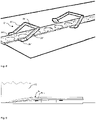
- Fig. 6 shows the rail element and system of figures 3 and 5 in a perspective view arranged partly recessed in the road surface of a road section, where the upper part of the rail element is transparent for illustrative purposes. Spacing elements 10', 10", 10'" and through channels 13 can be seen (not all are provided with figure references).
- Fig. 7 shows a side view of the rail element and system in figures 3 , 5 and 6 . As illustrated, the through channels 13 allow water and dirt to flow straight through the rail element.
- Fig. 8 shows a perspective view of the rail element and system in figures 3 , 5-7 together with a current collector illustrated in two different positions.
- the current collector 2" comprises contact elements 2a", 2b" adapted to connect electrically and mechanically with the conductors in the rail element.
- the contact elements are connected to collector arms 2c", 2d" configured to rotate vertically and horizontally to allow the contact elements to enter the groves from the side.
- the collector arms are attached to a sliding device 2e" adapted to be displaceable in a lateral direction of the vehicle at an underside thereof. In the first illustrated position to the left in fig. 8 , the contact elements are in contact with the conductors.
- the collector arms In the second illustrated position, the collector arms have been rotated laterally outwards such that the contact elements no longer are disposed in the grooves.
- the contact elements are provided with an inclined front portions in the same manner as shown in fig. 2 , although inclined to a lesser extent.
- the current collector may be of the type described in applicants' patent application SE 19206292-5 , although with the contact elements disposed at right angle relative to the disclosure therein, to allow the contact elements to enter the laterally directed grooves of the present invention by means of sideways rotation around the rotational axis.
- Fig. 9 shows a cross-section view of a similar embodiment as in fig. 3 , except that the upper layer 9a' 1 of the upper part 9a' is made from a resilient/flexible material which means that the upper part 9a' is bent down to make contact with the lower part or road surface when the rail element is run over by a vehicle tire 15.
- the conductors may be arranged at different positions inside the grooves, for instance at a lower portion thereof, and may have a different shape or cross-section.
- the spacing means may be different, and may even be formed by a single spacing element provided with through holes for drainage.
- the current collector may be of any known type or modification thereof which allows its contact element to co-act with the laterally directed grooves.
Landscapes
- Engineering & Computer Science (AREA)
- Mechanical Engineering (AREA)
- Current-Collector Devices For Electrically Propelled Vehicles (AREA)
- Electric Propulsion And Braking For Vehicles (AREA)
Priority Applications (2)
| Application Number | Priority Date | Filing Date | Title |
|---|---|---|---|
| EP20201861.0A EP3984812B1 (fr) | 2020-10-14 | 2020-10-14 | Élément de rail et système d'alimentation électrique de véhicules routiers |
| PCT/EP2021/078411 WO2022079153A1 (fr) | 2020-10-14 | 2021-10-14 | Élément de rail et système d'alimentation électrique de véhicules routiers |
Applications Claiming Priority (1)
| Application Number | Priority Date | Filing Date | Title |
|---|---|---|---|
| EP20201861.0A EP3984812B1 (fr) | 2020-10-14 | 2020-10-14 | Élément de rail et système d'alimentation électrique de véhicules routiers |
Publications (3)
| Publication Number | Publication Date |
|---|---|
| EP3984812A1 true EP3984812A1 (fr) | 2022-04-20 |
| EP3984812B1 EP3984812B1 (fr) | 2023-08-02 |
| EP3984812C0 EP3984812C0 (fr) | 2023-08-02 |
Family
ID=72885463
Family Applications (1)
| Application Number | Title | Priority Date | Filing Date |
|---|---|---|---|
| EP20201861.0A Active EP3984812B1 (fr) | 2020-10-14 | 2020-10-14 | Élément de rail et système d'alimentation électrique de véhicules routiers |
Country Status (2)
| Country | Link |
|---|---|
| EP (1) | EP3984812B1 (fr) |
| WO (1) | WO2022079153A1 (fr) |
Citations (5)
| Publication number | Priority date | Publication date | Assignee | Title |
|---|---|---|---|---|
| GB1341777A (en) * | 1971-05-11 | 1973-12-25 | Merlin Gerin | Linearly extending electrical distribution system having conductor rails |
| DE102006027906A1 (de) * | 2006-06-17 | 2007-12-20 | Joachim Dengler | Stromschienensystem zur Führung und Stromversorgung von Elektro-Straßenfahrzeugen |
| EP1763160B1 (fr) | 2005-09-09 | 2008-02-13 | M-Stack Limited | Appareil et procédé de sommation de mesures de puissance dans l'équipement d'utilisateur dans un système de télécommunication mobile |
| WO2011123046A1 (fr) | 2010-04-01 | 2011-10-06 | Elways Ab | Système conçu pour un ou plusieurs véhicules propulsables électriquement (moyens de contact en forme de bras) |
| EP2994337B1 (fr) | 2013-05-07 | 2019-07-10 | Elways AB | Piste et contact insensibles aux intemperies pour une alimentation electrique de vehicules de route |
-
2020
- 2020-10-14 EP EP20201861.0A patent/EP3984812B1/fr active Active
-
2021
- 2021-10-14 WO PCT/EP2021/078411 patent/WO2022079153A1/fr not_active Ceased
Patent Citations (5)
| Publication number | Priority date | Publication date | Assignee | Title |
|---|---|---|---|---|
| GB1341777A (en) * | 1971-05-11 | 1973-12-25 | Merlin Gerin | Linearly extending electrical distribution system having conductor rails |
| EP1763160B1 (fr) | 2005-09-09 | 2008-02-13 | M-Stack Limited | Appareil et procédé de sommation de mesures de puissance dans l'équipement d'utilisateur dans un système de télécommunication mobile |
| DE102006027906A1 (de) * | 2006-06-17 | 2007-12-20 | Joachim Dengler | Stromschienensystem zur Führung und Stromversorgung von Elektro-Straßenfahrzeugen |
| WO2011123046A1 (fr) | 2010-04-01 | 2011-10-06 | Elways Ab | Système conçu pour un ou plusieurs véhicules propulsables électriquement (moyens de contact en forme de bras) |
| EP2994337B1 (fr) | 2013-05-07 | 2019-07-10 | Elways AB | Piste et contact insensibles aux intemperies pour une alimentation electrique de vehicules de route |
Also Published As
| Publication number | Publication date |
|---|---|
| EP3984812B1 (fr) | 2023-08-02 |
| EP3984812C0 (fr) | 2023-08-02 |
| WO2022079153A1 (fr) | 2022-04-21 |
Similar Documents
| Publication | Publication Date | Title |
|---|---|---|
| ES2423059T3 (es) | Posicionamiento y/o fijación de una serie de secciones de línea eléctrica a lo largo de la trayectoria de un vehículo | |
| KR100940240B1 (ko) | 전기 자동차를 이용하는 운송 시스템 | |
| CN103687745B (zh) | 预制导体构造及其制造方法、道路结构及其建造方法 | |
| US9597969B2 (en) | Systems and methods for providing in-road electric conductivity boxes and on-vehicle descent and pivot contacts for vehicles | |
| EP0614425A1 (fr) | Systeme de transport pour vehicules electriques | |
| CN103687746A (zh) | 用于车辆特别是公路汽车的道路结构 | |
| KR20110089374A (ko) | 주행중에 충전할 수 있는 교통 시스템 | |
| KR20130137006A (ko) | 차량용 루트 및 그 루트의 구축 방법 | |
| CN104334399B (zh) | 绝缘段、供电导轨及轨道类交通系统 | |
| BR102018008211B1 (pt) | Segmento de trilho de um sistema de alimentação elétrica no solo para veículos terrestres e estrada compreendendo um sistema de alimentação elétrica no solo para veículos terrestres | |
| WO2021051233A1 (fr) | Agencement de charge statique et procédé de charge | |
| EP3984812A1 (fr) | Élément de rail et système d'alimentation électrique de véhicules routiers | |
| KR102274987B1 (ko) | 고가식 충전차용 전용도로 시스템 | |
| US8141690B2 (en) | Current collecting contact member | |
| SE545720C2 (en) | Cast Curbstone and Charging Post | |
| CN114929505B (zh) | 包括集电器的电推进式车辆 | |
| EP4157671B1 (fr) | Piste de route électrique | |
| US10167600B2 (en) | Particle removing arrangement for an electric vehicle | |
| CN102923011A (zh) | 双能源动力增程式无轨电车 | |
| WO2000046065A1 (fr) | Systeme de transport | |
| CN214295600U (zh) | 一种路面感应移动式供电装置 | |
| RU2359731C2 (ru) | Игрушечная автострада электроприводных транспортных средств | |
| CN216287783U (zh) | 一种用于内嵌式中低速磁浮交通设备的供电系统的绝缘装置 | |
| EP4031399A1 (fr) | Système d'alimentation électrique de véhicules routiers | |
| RU2384425C2 (ru) | Система электросетевого транспорта на пневмоходу |
Legal Events
| Date | Code | Title | Description |
|---|---|---|---|
| STAA | Information on the status of an ep patent application or granted ep patent |
Free format text: STATUS: EXAMINATION IS IN PROGRESS |
|
| PUAI | Public reference made under article 153(3) epc to a published international application that has entered the european phase |
Free format text: ORIGINAL CODE: 0009012 |
|
| 17P | Request for examination filed |
Effective date: 20210428 |
|
| AK | Designated contracting states |
Kind code of ref document: A1 Designated state(s): AL AT BE BG CH CY CZ DE DK EE ES FI FR GB GR HR HU IE IS IT LI LT LU LV MC MK MT NL NO PL PT RO RS SE SI SK SM TR |
|
| GRAP | Despatch of communication of intention to grant a patent |
Free format text: ORIGINAL CODE: EPIDOSNIGR1 |
|
| STAA | Information on the status of an ep patent application or granted ep patent |
Free format text: STATUS: GRANT OF PATENT IS INTENDED |
|
| INTG | Intention to grant announced |
Effective date: 20220623 |
|
| GRAJ | Information related to disapproval of communication of intention to grant by the applicant or resumption of examination proceedings by the epo deleted |
Free format text: ORIGINAL CODE: EPIDOSDIGR1 |
|
| STAA | Information on the status of an ep patent application or granted ep patent |
Free format text: STATUS: EXAMINATION IS IN PROGRESS |
|
| INTC | Intention to grant announced (deleted) | ||
| GRAP | Despatch of communication of intention to grant a patent |
Free format text: ORIGINAL CODE: EPIDOSNIGR1 |
|
| STAA | Information on the status of an ep patent application or granted ep patent |
Free format text: STATUS: GRANT OF PATENT IS INTENDED |
|
| INTG | Intention to grant announced |
Effective date: 20230104 |
|
| GRAJ | Information related to disapproval of communication of intention to grant by the applicant or resumption of examination proceedings by the epo deleted |
Free format text: ORIGINAL CODE: EPIDOSDIGR1 |
|
| STAA | Information on the status of an ep patent application or granted ep patent |
Free format text: STATUS: EXAMINATION IS IN PROGRESS |
|
| GRAP | Despatch of communication of intention to grant a patent |
Free format text: ORIGINAL CODE: EPIDOSNIGR1 |
|
| STAA | Information on the status of an ep patent application or granted ep patent |
Free format text: STATUS: GRANT OF PATENT IS INTENDED |
|
| INTC | Intention to grant announced (deleted) | ||
| INTG | Intention to grant announced |
Effective date: 20230307 |
|
| GRAS | Grant fee paid |
Free format text: ORIGINAL CODE: EPIDOSNIGR3 |
|
| GRAA | (expected) grant |
Free format text: ORIGINAL CODE: 0009210 |
|
| STAA | Information on the status of an ep patent application or granted ep patent |
Free format text: STATUS: THE PATENT HAS BEEN GRANTED |
|
| AK | Designated contracting states |
Kind code of ref document: B1 Designated state(s): AL AT BE BG CH CY CZ DE DK EE ES FI FR GB GR HR HU IE IS IT LI LT LU LV MC MK MT NL NO PL PT RO RS SE SI SK SM TR |
|
| REG | Reference to a national code |
Ref country code: GB Ref legal event code: FG4D |
|
| REG | Reference to a national code |
Ref country code: CH Ref legal event code: EP |
|
| REG | Reference to a national code |
Ref country code: DE Ref legal event code: R096 Ref document number: 602020014842 Country of ref document: DE |
|
| REG | Reference to a national code |
Ref country code: IE Ref legal event code: FG4D |
|
| U01 | Request for unitary effect filed |
Effective date: 20230830 |
|
| U07 | Unitary effect registered |
Designated state(s): AT BE BG DE DK EE FI FR IT LT LU LV MT NL PT SE SI Effective date: 20230906 |
|
| U20 | Renewal fee for the european patent with unitary effect paid |
Year of fee payment: 4 Effective date: 20231026 |
|
| PG25 | Lapsed in a contracting state [announced via postgrant information from national office to epo] |
Ref country code: GR Free format text: LAPSE BECAUSE OF FAILURE TO SUBMIT A TRANSLATION OF THE DESCRIPTION OR TO PAY THE FEE WITHIN THE PRESCRIBED TIME-LIMIT Effective date: 20231103 |
|
| PG25 | Lapsed in a contracting state [announced via postgrant information from national office to epo] |
Ref country code: IS Free format text: LAPSE BECAUSE OF FAILURE TO SUBMIT A TRANSLATION OF THE DESCRIPTION OR TO PAY THE FEE WITHIN THE PRESCRIBED TIME-LIMIT Effective date: 20231202 |
|
| PG25 | Lapsed in a contracting state [announced via postgrant information from national office to epo] |
Ref country code: RS Free format text: LAPSE BECAUSE OF FAILURE TO SUBMIT A TRANSLATION OF THE DESCRIPTION OR TO PAY THE FEE WITHIN THE PRESCRIBED TIME-LIMIT Effective date: 20230802 Ref country code: NO Free format text: LAPSE BECAUSE OF FAILURE TO SUBMIT A TRANSLATION OF THE DESCRIPTION OR TO PAY THE FEE WITHIN THE PRESCRIBED TIME-LIMIT Effective date: 20231102 Ref country code: IS Free format text: LAPSE BECAUSE OF FAILURE TO SUBMIT A TRANSLATION OF THE DESCRIPTION OR TO PAY THE FEE WITHIN THE PRESCRIBED TIME-LIMIT Effective date: 20231202 Ref country code: HR Free format text: LAPSE BECAUSE OF FAILURE TO SUBMIT A TRANSLATION OF THE DESCRIPTION OR TO PAY THE FEE WITHIN THE PRESCRIBED TIME-LIMIT Effective date: 20230802 Ref country code: GR Free format text: LAPSE BECAUSE OF FAILURE TO SUBMIT A TRANSLATION OF THE DESCRIPTION OR TO PAY THE FEE WITHIN THE PRESCRIBED TIME-LIMIT Effective date: 20231103 |
|
| PG25 | Lapsed in a contracting state [announced via postgrant information from national office to epo] |
Ref country code: PL Free format text: LAPSE BECAUSE OF FAILURE TO SUBMIT A TRANSLATION OF THE DESCRIPTION OR TO PAY THE FEE WITHIN THE PRESCRIBED TIME-LIMIT Effective date: 20230802 |
|
| PG25 | Lapsed in a contracting state [announced via postgrant information from national office to epo] |
Ref country code: ES Free format text: LAPSE BECAUSE OF FAILURE TO SUBMIT A TRANSLATION OF THE DESCRIPTION OR TO PAY THE FEE WITHIN THE PRESCRIBED TIME-LIMIT Effective date: 20230802 |
|
| PG25 | Lapsed in a contracting state [announced via postgrant information from national office to epo] |
Ref country code: SM Free format text: LAPSE BECAUSE OF FAILURE TO SUBMIT A TRANSLATION OF THE DESCRIPTION OR TO PAY THE FEE WITHIN THE PRESCRIBED TIME-LIMIT Effective date: 20230802 Ref country code: RO Free format text: LAPSE BECAUSE OF FAILURE TO SUBMIT A TRANSLATION OF THE DESCRIPTION OR TO PAY THE FEE WITHIN THE PRESCRIBED TIME-LIMIT Effective date: 20230802 Ref country code: ES Free format text: LAPSE BECAUSE OF FAILURE TO SUBMIT A TRANSLATION OF THE DESCRIPTION OR TO PAY THE FEE WITHIN THE PRESCRIBED TIME-LIMIT Effective date: 20230802 Ref country code: CZ Free format text: LAPSE BECAUSE OF FAILURE TO SUBMIT A TRANSLATION OF THE DESCRIPTION OR TO PAY THE FEE WITHIN THE PRESCRIBED TIME-LIMIT Effective date: 20230802 Ref country code: SK Free format text: LAPSE BECAUSE OF FAILURE TO SUBMIT A TRANSLATION OF THE DESCRIPTION OR TO PAY THE FEE WITHIN THE PRESCRIBED TIME-LIMIT Effective date: 20230802 |
|
| REG | Reference to a national code |
Ref country code: DE Ref legal event code: R097 Ref document number: 602020014842 Country of ref document: DE |
|
| PG25 | Lapsed in a contracting state [announced via postgrant information from national office to epo] |
Ref country code: MC Free format text: LAPSE BECAUSE OF FAILURE TO SUBMIT A TRANSLATION OF THE DESCRIPTION OR TO PAY THE FEE WITHIN THE PRESCRIBED TIME-LIMIT Effective date: 20230802 |
|
| REG | Reference to a national code |
Ref country code: CH Ref legal event code: PL |
|
| PLBE | No opposition filed within time limit |
Free format text: ORIGINAL CODE: 0009261 |
|
| STAA | Information on the status of an ep patent application or granted ep patent |
Free format text: STATUS: NO OPPOSITION FILED WITHIN TIME LIMIT |
|
| RAP2 | Party data changed (patent owner data changed or rights of a patent transferred) |
Owner name: EVIAS AB |
|
| U1K | Transfer of rights of the unitary patent after the registration of the unitary effect |
Owner name: EVIAS AB; SE |
|
| 26N | No opposition filed |
Effective date: 20240503 |
|
| PG25 | Lapsed in a contracting state [announced via postgrant information from national office to epo] |
Ref country code: CH Free format text: LAPSE BECAUSE OF NON-PAYMENT OF DUE FEES Effective date: 20231031 |
|
| PG25 | Lapsed in a contracting state [announced via postgrant information from national office to epo] |
Ref country code: CH Free format text: LAPSE BECAUSE OF NON-PAYMENT OF DUE FEES Effective date: 20231031 |
|
| PG25 | Lapsed in a contracting state [announced via postgrant information from national office to epo] |
Ref country code: IE Free format text: LAPSE BECAUSE OF NON-PAYMENT OF DUE FEES Effective date: 20231014 |
|
| PG25 | Lapsed in a contracting state [announced via postgrant information from national office to epo] |
Ref country code: IE Free format text: LAPSE BECAUSE OF NON-PAYMENT OF DUE FEES Effective date: 20231014 |
|
| U20 | Renewal fee for the european patent with unitary effect paid |
Year of fee payment: 5 Effective date: 20241025 |
|
| PGFP | Annual fee paid to national office [announced via postgrant information from national office to epo] |
Ref country code: GB Payment date: 20241022 Year of fee payment: 5 |
|
| PG25 | Lapsed in a contracting state [announced via postgrant information from national office to epo] |
Ref country code: CY Free format text: LAPSE BECAUSE OF FAILURE TO SUBMIT A TRANSLATION OF THE DESCRIPTION OR TO PAY THE FEE WITHIN THE PRESCRIBED TIME-LIMIT; INVALID AB INITIO Effective date: 20201014 |
|
| PG25 | Lapsed in a contracting state [announced via postgrant information from national office to epo] |
Ref country code: HU Free format text: LAPSE BECAUSE OF FAILURE TO SUBMIT A TRANSLATION OF THE DESCRIPTION OR TO PAY THE FEE WITHIN THE PRESCRIBED TIME-LIMIT; INVALID AB INITIO Effective date: 20201014 |
|
| PG25 | Lapsed in a contracting state [announced via postgrant information from national office to epo] |
Ref country code: TR Free format text: LAPSE BECAUSE OF FAILURE TO SUBMIT A TRANSLATION OF THE DESCRIPTION OR TO PAY THE FEE WITHIN THE PRESCRIBED TIME-LIMIT Effective date: 20230802 |