EP3984930A1 - Rampe de chargement avec compensation de poids - Google Patents
Rampe de chargement avec compensation de poids Download PDFInfo
- Publication number
- EP3984930A1 EP3984930A1 EP21075014.7A EP21075014A EP3984930A1 EP 3984930 A1 EP3984930 A1 EP 3984930A1 EP 21075014 A EP21075014 A EP 21075014A EP 3984930 A1 EP3984930 A1 EP 3984930A1
- Authority
- EP
- European Patent Office
- Prior art keywords
- loading
- lip
- middle lip
- supporting
- rest
- Prior art date
- Legal status (The legal status is an assumption and is not a legal conclusion. Google has not performed a legal analysis and makes no representation as to the accuracy of the status listed.)
- Pending
Links
Images


Classifications
-
- B—PERFORMING OPERATIONS; TRANSPORTING
- B65—CONVEYING; PACKING; STORING; HANDLING THIN OR FILAMENTARY MATERIAL
- B65G—TRANSPORT OR STORAGE DEVICES, e.g. CONVEYORS FOR LOADING OR TIPPING, SHOP CONVEYOR SYSTEMS OR PNEUMATIC TUBE CONVEYORS
- B65G69/00—Auxiliary measures taken, or devices used, in connection with loading or unloading
- B65G69/28—Loading ramps; Loading docks
- B65G69/2805—Loading ramps; Loading docks permanently installed on the dock
- B65G69/2811—Loading ramps; Loading docks permanently installed on the dock pivoting ramps
- B65G69/2817—Loading ramps; Loading docks permanently installed on the dock pivoting ramps with fluid-operated means
- B65G69/2829—Loading ramps; Loading docks permanently installed on the dock pivoting ramps with fluid-operated means extensible by sliding parts
-
- B—PERFORMING OPERATIONS; TRANSPORTING
- B65—CONVEYING; PACKING; STORING; HANDLING THIN OR FILAMENTARY MATERIAL
- B65G—TRANSPORT OR STORAGE DEVICES, e.g. CONVEYORS FOR LOADING OR TIPPING, SHOP CONVEYOR SYSTEMS OR PNEUMATIC TUBE CONVEYORS
- B65G69/00—Auxiliary measures taken, or devices used, in connection with loading or unloading
- B65G69/28—Loading ramps; Loading docks
- B65G69/2805—Loading ramps; Loading docks permanently installed on the dock
- B65G69/2811—Loading ramps; Loading docks permanently installed on the dock pivoting ramps
- B65G69/2858—Loading ramps; Loading docks permanently installed on the dock pivoting ramps with weight counterbalancing means
Definitions
- the present invention relates to a loading ramp for loading platforms, formed by a frame with a bridge plate which at its loading platform side rotatably is connected to the loading platform and at its front side is provided with a retractable and extendable supporting plate, that is intended to rest upon the loading floor of a vehicle, which supporting plate is formed by a middle lip and on either side a left side lip and a right side lip.
- the width of the loading space does not permit this and only the middle lip is lowered onto the loading floor.
- the vehicle When loading the vehicle, the vehicle will give way due to the increasing weight and this will sag downwards.
- the bridge plate turns with this movement and continues to rest on the loading floor of the vehicle.
- the invention aims to obviate this drawback of the known loading ramp.
- the loading ramp according to the invention to that end is characterized in that a supporting element is provided on which the middle lip can rest in a position, which supporting element is provided onto a supporting part, whereby in between the supporting element and the supporting part a spring is provided.
- the supporting element is formed by a roller.
- the supporting part is formed by a beam.
- the supporting part or the beam is provided transverse to the path of movement of the middle lip.
- the supporting part or the beam is mounted at the one outer end to the left side lip and with the other outer end is mounted to the right side lip.
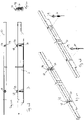
- Figure 1 shows a perspective view, taken apart, of an example of an embodiment of the loading ramp according to the invention.
- the figures 2a, 2b and 2c show a schematic top view of an example of an embodiment of the loading ramp according to the invention.
- the figures 3a, 3b and 3c show a schematic bottom view of an example of an embodiment of the loading ramp according to the invention.
- FIG. 4a, 4b, 4c, 4d and 4e show a detail, respectively top, side and perspective views of a beam applied in the example of an embodiment shown in figure 1 .
- the loading ramp 1 for a loading platform comprises a frame 2 with a bridge plate 3 which at its loading platform side 4 is rotatably connected to the loading platform and at its front side 5 is provided with a supporting plate 6 that is retractable and extendable in horizontal direction.
- the supporting plate 6 is formed by a middle lip 7 and on either side a left side lip 8 and a right side lip 9. These are intended to rest upon the loading floor of a vehicle.
- the supporting plate 6 for a good understanding of the invention, is shown already pulled out to some extent.
- the supporting plate 6 is more or less stored within the bridge plate 3 and from there does not protrude to the front.
- the middle lip 7 and the side lips 8 and 9 can be positioned, from a rest position shown in the figures 2a and 3a , in to a first position, shown in the figures 2b and 3b , in which the front edge 10 of the middle lip 7 and the front edges 11 of the side lips 8, 9 find themselves at a substantially same distance relative to the front side 5 of the bridge plate 3. Seen from the left to the right in the figures 2b and 3b the front edge 10 and the front edges 11 run in a more less straight line.
- the middle lip 7 and the side lips 8, 9 are positioned in a second position, shown in the figures 1 , 2c and 3c , in which the front edge 10 of the middle lip 7 finds itself at a distance from the front side 5 of the bridge plate 3 that is greater than the distance at which the front edges 11 of the side lips 8, 9 find themselves from the front side 5 of the bridge plate 3. In this position only the middle lip 7 rests upon the loading floor 14 of a delivery van 15 (indicated with dotted line in the figures 2c and 3c ).
- the bridge plate 3 is provided with a transverse beam 16, shown in figure 1 (not shown in the figures 3a-3c ), which supports the supporting plate 6 in the bridge plate and on which the supporting plate 6 can be slid in and slid out in horizontal direction.
- the transverse beam 16 to that end is provided with sliding strips 17.
- the transverse beam 16 at the same time constitutes a pivoting point along which the middle lip 7 can turn in the bridge plate 3 from out of a position in which the back side 20 of the middle lip 7 runs downwards and the front edge 10 of the middle lip runs upwards to into a position in which the back side 20 of the middle lip 7 runs upwards and the front edge 10 of the middle lip 7 runs downwards. In this last position the middle lip 7 tends to rest on the loading floor of the vehicle.
- a supporting part in the form of a beam 21 is provided, which beam 21 with the one outer end 22 is mounted underneath the left side lip 8 and with the other outer end 23 is mounted underneath the right side lip 9.
- the beam 21 extends underneath the middle lip 7.
- the middle lip 7 rests loose on the beam 21.
- a cylinder rod 24 of an hydraulic cylinder 25 the housing 26 of which is mounted to the bottom side of the middle lip 7.
- the cylinder 25 is in principle completely extended ( figures 2b and 3b ) and the side lips 8, 9 with the middle lip 7 come forward from out of the front side 5 of the bridge plate 3 in the direction of the vehicle that is to be loaded and unloaded, the moment the supporting plate 6 is slid out.
- the cylinder 25 is retracted whereby this pulls the beam 21 backwards, in the direction of the loading platform.
- the side lips 8, 9 mounted to the beam 21 go along with this movement, after which the middle lip 7 protrudes forward alone relative to the side lips 8, 9.
- the middle lip 7 can then be lowered on to the narrower loading floor 14 of a delivery van 15.
- a sensor is provided onto the beam 21.
- the middle lip 7 comes to rest on the loading floor 14 of the delivery van, the middle lip 7 is lifted from the beam 21.
- the distance that thereby comes about between the bottom side of the middle lip 7 and the beam 21 is detected by the sensor and this generates a signal, by means of which by way of a controlling device the drive of the lifting cylinders 27 is operable, such that the movement downwards of the bridge plate 3 is stopped.
- the two supporting elements 28, in this example of an embodiment two rollers 29, are provided onto which the middle lip 7 can rest loose in the rest position. Further these rollers 29 are provided onto the compression springs 30, that is to say these compression springs 30 are provided in between the rollers 29 and the beam 21, as can be seen in the detail shown in figure 4e .
- the middle lip 7 When the middle lip comes to rest on the loading floor 14 of the delivery van 15 the middle lip 7 is lifted a length upwards from the beam 21 by that floor 14 . This middle lip 7 then is no longer supported by the beam 21. However, by the compression springs 30 the rolls 29 are pushed a length upwards and the beam 21 continues to support the middle lip 7 indirectly by way of the springs 30 and the rollers 29.
- the supporting part onto which the rollers 29 and the springs 30 are provided is formed by the beam 21 with thereon at the same time the cylinder rod 24 of the cylinder 25 by means of which the side lips are retracted relative to the middle lip.
- the supporting part may be formed by a component being provided separately from the beam 21.
- the compression spring 30 or compressions springs 30 have a sufficient weakness to already be compressed, more in particular already be substantially compressed, when the full weight of only the middle lip 7 rests on the supporting element or the supporting elements 28.
- the compression spring 30 or compressions springs 30 are sufficiently strong or stiff to spring outwards, when the middle lip 7 comes to rest on the loading floor 14 of the delivery van 15 but the supporting element or the supporting elements 28 do still bear a part of the weight of the middle lip 7.
- the middle lip 7 then still is pushed temporarily upwards by the spring or springs 30, so that the full weight of the middle lip 7 does not directly rest on the loading floor 14, and there is sufficient time for the operation of the lifting cylinders to take over the weight of the middle lip.
Landscapes
- Engineering & Computer Science (AREA)
- Mechanical Engineering (AREA)
- Vehicle Step Arrangements And Article Storage (AREA)
- Bridges Or Land Bridges (AREA)
Applications Claiming Priority (1)
| Application Number | Priority Date | Filing Date | Title |
|---|---|---|---|
| NL1043819A NL1043819B1 (nl) | 2020-10-14 | 2020-10-14 | Laadbrug met gewichtscompensatie. |
Publications (1)
| Publication Number | Publication Date |
|---|---|
| EP3984930A1 true EP3984930A1 (fr) | 2022-04-20 |
Family
ID=76284089
Family Applications (1)
| Application Number | Title | Priority Date | Filing Date |
|---|---|---|---|
| EP21075014.7A Pending EP3984930A1 (fr) | 2020-10-14 | 2021-10-12 | Rampe de chargement avec compensation de poids |
Country Status (2)
| Country | Link |
|---|---|
| EP (1) | EP3984930A1 (fr) |
| NL (1) | NL1043819B1 (fr) |
Citations (6)
| Publication number | Priority date | Publication date | Assignee | Title |
|---|---|---|---|---|
| GB1276858A (en) * | 1969-06-23 | 1972-06-07 | G E & L V Rich Ltd | Packaway dock levellers |
| DE3710109C1 (fr) * | 1987-03-27 | 1988-04-07 | Kurt 3015 Wennigsen De Alten | |
| DE4408069C1 (de) * | 1994-03-10 | 1995-04-13 | Alten K | Überfahrbrücke für Rampen |
| FR2723360A1 (fr) * | 1994-08-03 | 1996-02-09 | Alten K | Niveleur de quai |
| US6081954A (en) * | 1998-03-17 | 2000-07-04 | Systems, Inc. | Dock leveler with linearly translatable lip |
| DE102020109838A1 (de) * | 2019-04-08 | 2020-10-08 | Stertil B.V. | Überladebrücke mit verstellbaren seitenelementen, damit ausgestattete(s) verladestation und distributionszentrum und dazu bestimmtes verfahren |
-
2020
- 2020-10-14 NL NL1043819A patent/NL1043819B1/nl active
-
2021
- 2021-10-12 EP EP21075014.7A patent/EP3984930A1/fr active Pending
Patent Citations (6)
| Publication number | Priority date | Publication date | Assignee | Title |
|---|---|---|---|---|
| GB1276858A (en) * | 1969-06-23 | 1972-06-07 | G E & L V Rich Ltd | Packaway dock levellers |
| DE3710109C1 (fr) * | 1987-03-27 | 1988-04-07 | Kurt 3015 Wennigsen De Alten | |
| DE4408069C1 (de) * | 1994-03-10 | 1995-04-13 | Alten K | Überfahrbrücke für Rampen |
| FR2723360A1 (fr) * | 1994-08-03 | 1996-02-09 | Alten K | Niveleur de quai |
| US6081954A (en) * | 1998-03-17 | 2000-07-04 | Systems, Inc. | Dock leveler with linearly translatable lip |
| DE102020109838A1 (de) * | 2019-04-08 | 2020-10-08 | Stertil B.V. | Überladebrücke mit verstellbaren seitenelementen, damit ausgestattete(s) verladestation und distributionszentrum und dazu bestimmtes verfahren |
Also Published As
| Publication number | Publication date |
|---|---|
| NL1043819B1 (nl) | 2022-06-08 |
Similar Documents
| Publication | Publication Date | Title |
|---|---|---|
| US7351027B2 (en) | Vehicle loader mechanism | |
| US6019567A (en) | Slidable load lifting system | |
| US7931138B2 (en) | Automatic tire transfer apparatus using traverser | |
| US20090272953A1 (en) | Lift apparatus | |
| KR20010013117A (ko) | 차량 화물 리프트 | |
| US5217342A (en) | Self-loading and unloading forklift truck | |
| EP3984930A1 (fr) | Rampe de chargement avec compensation de poids | |
| CA3076781C (fr) | Verin de vehicule | |
| US6932401B1 (en) | Casket transporting apparatus | |
| US11247600B2 (en) | Carrier with slidable bed and zero-degree load angle | |
| JP4912930B2 (ja) | 貨物自動車の荷台傾斜装置 | |
| JP3792151B2 (ja) | 床下格納式昇降装置 | |
| JP5178434B2 (ja) | 車両用床下格納式荷役装置 | |
| US11535142B1 (en) | Lowerable and raisable vehicle trailer system, and method of operating a vehicle trailer system | |
| US3107021A (en) | Vehicle body loading and unloading mechanisms | |
| US8714894B2 (en) | Drive-over collapsible fender | |
| JP4815290B2 (ja) | 車両用床下格納式荷役装置 | |
| US20070092363A1 (en) | Rolling tilt deck for a truck bed | |
| JP3769170B2 (ja) | 貨物自動車におけるボデーの積卸装置 | |
| JP5005433B2 (ja) | 車両用荷役装置 | |
| AU2017293650B2 (en) | A trailer assembly | |
| US4549844A (en) | Roller bed vehicle | |
| EP3984929A1 (fr) | Rampe de chargement | |
| US20060182567A1 (en) | Glass loading rack | |
| JP6525799B2 (ja) | 荷受台昇降装置 |
Legal Events
| Date | Code | Title | Description |
|---|---|---|---|
| PUAI | Public reference made under article 153(3) epc to a published international application that has entered the european phase |
Free format text: ORIGINAL CODE: 0009012 |
|
| STAA | Information on the status of an ep patent application or granted ep patent |
Free format text: STATUS: THE APPLICATION HAS BEEN PUBLISHED |
|
| AK | Designated contracting states |
Kind code of ref document: A1 Designated state(s): AL AT BE BG CH CY CZ DE DK EE ES FI FR GB GR HR HU IE IS IT LI LT LU LV MC MK MT NL NO PL PT RO RS SE SI SK SM TR |
|
| STAA | Information on the status of an ep patent application or granted ep patent |
Free format text: STATUS: REQUEST FOR EXAMINATION WAS MADE |
|
| 17P | Request for examination filed |
Effective date: 20221019 |
|
| RBV | Designated contracting states (corrected) |
Designated state(s): AL AT BE BG CH CY CZ DE DK EE ES FI FR GB GR HR HU IE IS IT LI LT LU LV MC MK MT NL NO PL PT RO RS SE SI SK SM TR |
|
| STAA | Information on the status of an ep patent application or granted ep patent |
Free format text: STATUS: EXAMINATION IS IN PROGRESS |
|
| 17Q | First examination report despatched |
Effective date: 20240514 |