EP3985190A1 - Vorrichtung zum befestigen eines pfostens - Google Patents
Vorrichtung zum befestigen eines pfostens Download PDFInfo
- Publication number
- EP3985190A1 EP3985190A1 EP21202954.0A EP21202954A EP3985190A1 EP 3985190 A1 EP3985190 A1 EP 3985190A1 EP 21202954 A EP21202954 A EP 21202954A EP 3985190 A1 EP3985190 A1 EP 3985190A1
- Authority
- EP
- European Patent Office
- Prior art keywords
- double wall
- panel
- sheath
- assembly
- junction structure
- Prior art date
- Legal status (The legal status is an assumption and is not a legal conclusion. Google has not performed a legal analysis and makes no representation as to the accuracy of the status listed.)
- Pending
Links
- 238000004873 anchoring Methods 0.000 claims abstract description 53
- 238000000034 method Methods 0.000 claims description 12
- 230000000284 resting effect Effects 0.000 claims description 3
- 238000005304 joining Methods 0.000 claims description 2
- 238000005192 partition Methods 0.000 claims description 2
- 238000010276 construction Methods 0.000 description 19
- 239000000463 material Substances 0.000 description 13
- 230000000295 complement effect Effects 0.000 description 8
- 230000002093 peripheral effect Effects 0.000 description 7
- 238000009415 formwork Methods 0.000 description 6
- 239000000470 constituent Substances 0.000 description 4
- 238000009434 installation Methods 0.000 description 4
- 230000000903 blocking effect Effects 0.000 description 3
- 238000003780 insertion Methods 0.000 description 3
- 230000037431 insertion Effects 0.000 description 3
- 238000012423 maintenance Methods 0.000 description 3
- 230000004888 barrier function Effects 0.000 description 2
- 238000005266 casting Methods 0.000 description 2
- 238000006073 displacement reaction Methods 0.000 description 2
- 238000004519 manufacturing process Methods 0.000 description 2
- 239000002184 metal Substances 0.000 description 2
- 238000012546 transfer Methods 0.000 description 2
- 238000003466 welding Methods 0.000 description 2
- 230000001186 cumulative effect Effects 0.000 description 1
- 238000005520 cutting process Methods 0.000 description 1
- 230000003116 impacting effect Effects 0.000 description 1
- 230000003993 interaction Effects 0.000 description 1
- 238000012986 modification Methods 0.000 description 1
- 230000004048 modification Effects 0.000 description 1
- 230000002787 reinforcement Effects 0.000 description 1
- 238000007711 solidification Methods 0.000 description 1
- 230000008023 solidification Effects 0.000 description 1
- 238000006467 substitution reaction Methods 0.000 description 1
- 239000011800 void material Substances 0.000 description 1
Images


Classifications
-
- E—FIXED CONSTRUCTIONS
- E04—BUILDING
- E04B—GENERAL BUILDING CONSTRUCTIONS; WALLS, e.g. PARTITIONS; ROOFS; FLOORS; CEILINGS; INSULATION OR OTHER PROTECTION OF BUILDINGS
- E04B2/00—Walls, e.g. partitions, for buildings; Wall construction with regard to insulation; Connections specially adapted to walls
- E04B2/84—Walls made by casting, pouring, or tamping in situ
- E04B2/86—Walls made by casting, pouring, or tamping in situ made in permanent forms
- E04B2/8605—Walls made by casting, pouring, or tamping in situ made in permanent forms without spacers
-
- E—FIXED CONSTRUCTIONS
- E04—BUILDING
- E04G—SCAFFOLDING; FORMS; SHUTTERING; BUILDING IMPLEMENTS OR AIDS, OR THEIR USE; HANDLING BUILDING MATERIALS ON THE SITE; REPAIRING, BREAKING-UP OR OTHER WORK ON EXISTING BUILDINGS
- E04G17/00—Connecting or other auxiliary members for forms, falsework structures, or shutterings
- E04G17/002—Workplatforms, railings; Arrangements for pouring concrete, attached to the form
-
- E—FIXED CONSTRUCTIONS
- E04—BUILDING
- E04G—SCAFFOLDING; FORMS; SHUTTERING; BUILDING IMPLEMENTS OR AIDS, OR THEIR USE; HANDLING BUILDING MATERIALS ON THE SITE; REPAIRING, BREAKING-UP OR OTHER WORK ON EXISTING BUILDINGS
- E04G21/00—Preparing, conveying, or working-up building materials or building elements in situ; Other devices or measures for constructional work
- E04G21/32—Safety or protective measures for persons during the construction of buildings
- E04G21/3204—Safety or protective measures for persons during the construction of buildings against falling down
- E04G21/3219—Means supported by the building wall, e.g. security consoles
-
- E—FIXED CONSTRUCTIONS
- E04—BUILDING
- E04G—SCAFFOLDING; FORMS; SHUTTERING; BUILDING IMPLEMENTS OR AIDS, OR THEIR USE; HANDLING BUILDING MATERIALS ON THE SITE; REPAIRING, BREAKING-UP OR OTHER WORK ON EXISTING BUILDINGS
- E04G21/00—Preparing, conveying, or working-up building materials or building elements in situ; Other devices or measures for constructional work
- E04G21/32—Safety or protective measures for persons during the construction of buildings
- E04G21/3204—Safety or protective measures for persons during the construction of buildings against falling down
- E04G21/3223—Means supported by building floors or flat roofs, e.g. safety railings
- E04G21/3233—Means supported by building floors or flat roofs, e.g. safety railings without permanent provision in the floor or roof
- E04G21/3242—Means supported by building floors or flat roofs, e.g. safety railings without permanent provision in the floor or roof using clamps
-
- E—FIXED CONSTRUCTIONS
- E04—BUILDING
- E04B—GENERAL BUILDING CONSTRUCTIONS; WALLS, e.g. PARTITIONS; ROOFS; FLOORS; CEILINGS; INSULATION OR OTHER PROTECTION OF BUILDINGS
- E04B1/00—Constructions in general; Structures which are not restricted either to walls, e.g. partitions, or floors or ceilings or roofs
- E04B1/16—Structures made from masses, e.g. of concrete, cast or similarly formed in situ with or without making use of additional elements, such as permanent forms, substructures to be coated with load-bearing material
- E04B1/161—Structures made from masses, e.g. of concrete, cast or similarly formed in situ with or without making use of additional elements, such as permanent forms, substructures to be coated with load-bearing material with vertical and horizontal slabs, both being partially cast in situ
Definitions
- the present invention relates to the field of guardrail fixing devices and more particularly to the field of guardrail fixing devices on a double wall.
- one or more vertical walls form support elements intended to carry the platform.
- These vertical walls include receiving holes arranged vertically to receive railing posts.
- such holes occupied by railing posts at the upper surface of these support elements clutter the upper surface of the support elements for easy positioning of a platform.
- these support elements restrict the surface of the support elements able to carry a platform.
- anchoring devices have been developed to allow the fixing of guardrail posts on the vertical facades of double walls used as support elements.
- such anchoring devices produce parts projecting from the walls of the double walls and are complex to remove so that the walls of the panels of superimposed double walls have a uniform surface continuity without being altered.
- the object of the present invention is to overcome these drawbacks by proposing a solution which makes it possible to proceed with the assembly of one or more uprights of railings on double walls positioned vertically while optimizing the support surface of these double walls without impacting the vertical surfaces of the panels of these double walls.
- the invention thus relates to a device for fixing a post to a double wall arranged in a substantially vertical plane, characterized in that the fixing device comprises, on the one hand, a sleeve configured to receive at least a portion of a post, this sheath being associated with a mechanism for positioning the sheath along a substantially vertical axis and on the outer face of a panel of the double wall and, on the other hand, an anchoring assembly configured to fix the positioning mechanism and the sleeve with part of the double wall located within its thickness, the positioning mechanism being arranged to be positioned at a part of the upper surface of a double wall.
- the invention also relates to an assembly characterized in that it comprises a double wall panel and at least one fixing device according to the invention.
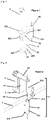
- FIG. 1 is an exploded schematic representation of several of the constituent elements of an example of a fastening device according to the invention.
- FIG. 2 is a schematic representation of the assembly of the constituent elements of an example of a fastening device according to the invention in association with a double wall panel.
- FIG. 3 is an exploded schematic representation of the constituent elements of a first example of an assembly incorporating a fixing device according to the invention in association with a double wall panel.
- FIG. 4 is a schematic representation of the constituent elements of a second example of an assembly incorporating a fixing device according to the invention in association with a double wall panel.
- FIG. 5 is a schematic representation of an example of pivoting of a junction structure of the inking assembly of an example of a fixing device according to the invention relative to a cover plate positioned on the upper surface of a wall panel.
- FIG. 6 is a diagrammatic representation in section of a kinematics of an example of a method for implementing an assembly according to the invention integrating a fastening device according to the invention in association with a double wall panel.
- the qualifiers "interior” and “exterior” should be understood by default in particular attributed to the panel surfaces 3 of the double wall 1 as referring to the particular positions of these surfaces with respect to the entire structure of the double wall. 1.
- the invention relates to a device for fixing a post 8 to a double wall 1 arranged in a substantially vertical plane, characterized in that the fixing device comprises, on the one hand, a sheath 2 configured to receive at least a portion of a post 8, this sleeve 2 being associated with a mechanism 4 for positioning the sleeve 2 along a substantially vertical axis and on the outer face of a panel 3 of the double wall 1 and, on the other hand, an anchoring assembly 5 configured to fix the positioning mechanism 4 and the sheath 2 with a part of the double wall 1 located inside its thickness, the anchor assembly 5 being arranged to be positioned above a part of the upper edge of a panel 3 of the double wall 1.
- the fastening device of the invention thus ensures, thanks to the positioning mechanism 4, the positioning of a sheath 2 for a post 8 so that this sheath 2 is held vertically in position relative to the outer wall of the panel 3.
- the anchor assembly 5 ensures the attachment of the positioning mechanism 4 and the sheath 2 on the panel 3 of the double wall 1 by operating a fixing by anchoring with the inside of the double wall 1, that is to say with a portion positioned inside the volume located between the two panels 3 of the double wall 1 and in particular in the upper part of this volume.
- This fixing by the anchor assembly 5 is carried out without inserting or crossing the surface of the panel 3 of the double wall 1, but by positioning a part of its structure over the upper edge of the panel 3 of the double wall 1.
- the dimensions of the fastening device of the invention and in particular of the sheath 2 are adapted to cooperate with a post 8 such as a post for a railing or a balustrade or one end of a railing upright or of railing.
- a post 8 such as a post for a railing or a balustrade or one end of a railing upright or of railing.
- the sheath 2 is configured to cooperate with a lower end such as a foot or a bearing portion of the guardrail or balustrade.
- the anchoring interface 51 is made in the form of an element or device structurally anchored in the interior volume of the double wall 1.
- This anchoring interface 51 is thus likely to take the form of a part adapted to be structurally integrated into the double wall 1 to form a point of attachment of the device of the invention to the double wall 1 which carries this device.
- This anchoring interface 51 is likely to correspond to a part or device integrated into the double wall 1 when the latter is installed on site or, alternatively, integrated into one or more elements of the double wall 1 prior to the installation of the double wall 1 on the site. It should be noted that this anchoring interface 51 which is integrated inside the double wall 1 cooperates with the junction structure 52 which, for its part, externalizes the fixing with the exterior of the double wall 1.
- the junction structure 52 is arranged to be positioned over the upper edge of a panel 3 of double wall 1.
- the latter has a substantially flattened arrangement so as to be able to press on an enlarged surface of the upper edge of the panel 3 of the double wall 1.
- the support exerted by the junction structure 52 under the weight of the post 8 inserted in the sheath 2 does not alter the upper edge of the panel 3 of the double wall 1.
- this flattened arrangement of the junction structure 52 is likely to limit the size of the device of the invention at the level of the upper surface of the panel 3 of the double wall 1 when a second double wall is positioned above the double wall 1 to which the device is attached fixing tif of the invention.
- this removable attachment is made in the form of a through hole 522 carried by the junction structure 52 and having dimensions and a shape complementary to at least a part of the peripheral surface of the sheath 2 positioned at the level of this through hole 522.
- the inner face of this through hole 522 is capable of comprising a thread arranged to cooperate with a complementary thread carried by the peripheral face of the sleeve 2.
- the insertion of the sleeve 2 in the through hole 522 is limited in its travel by the length of the thread and/or by a lip or an abutment flange carried by the peripheral face of the sheath 2 at its upper end or the upper edge of its thread.
- the removable fixing can be made by means of a fixing of the screw-nut type which secures the junction structure 52 with the positioning mechanism 4 by passing through two dedicated orifices carried respectively by the structure of junction 52 and the positioning mechanism 4. This removable fixing makes it possible to operate an easier assembly during the mounting of the fixing device of the invention on the double wall 1 but also during its dismantling.
- the elements of the device which are positioned against the outer wall of the panel 3 of the double wall 1, namely the positioning mechanism 4 and/or the sheath 2, are able to be removed.
- the junction structure 52 of the anchor assembly 5 is positioned between two panels 3 of double walls 1 superimposed, only this junction structure 52 protrudes through the junction of the surfaces of the two double walls 1.
- a worker is then likely to remove the part of the anchor assembly 5 which protrudes from the double wall 1 by cutting the portion of the junction structure 52 flush with the surface of the panel 3 of the double wall 1.
- the anchoring assembly 5 comprises at least a part of a joint 53 pivoting around an axis parallel to the axis of the sheath 2, this articulation 53 being configured to be positioned in the thickness of the double wall 1 with, on the one hand, a fixed part with the panel 3 of the double wall 1 formed by a portion of the anchoring interface 51 and, on the other hand, a movable part formed by a portion of the junction structure 52.
- the articulation 53 pivots between the anchoring interface 51 and the structure junction 52 allows movement of the junction structure 52 in a substantially horizontal plane which corresponds substantially to the plane of the edge or of the upper face of the panel 3 of the double wall 1 on which the junction structure 52 rests.
- e junction 52 is made by pivoting around a substantially vertical hinge pin 53 positioned at one end of the junction structure 52.
- This hinge pin 53 oriented vertically is arranged at the level of the assembly portions of the junction structure 52 with the anchoring interface 51. According to a specific example of construction, these assembly portions have complementary shapes to cooperate by producing a hinge-type arrangement.
- this hinge cooperation involves an axial portion 521 of the junction structure 52 arranged to pivot in a housing 512 of complementary shape integrated into the anchoring interface 51.
- the portion axial 521 and the complementary housing 512 have respective interaction surfaces positioned opposite each other and of circular shape.
- the axial portion 521 of the junction structure 52 forms a hinge arranged in an axial pivoting manner inside the corresponding housing 512 of the anchoring interface 51.
- the pivoting of the junction structure 52 with respect to the anchoring interface 51 makes it possible to operate a displacement of the structure of junction 52 at the level of the upper surface of the panel 3 of the double wall 1, so that the whole of the junction structure 52 is positioned at the level of the upper surface of the double wall 1.
- the junction structure 52 of the anchoring assembly 5 is capable of being moved in order to be fully inserted into the gap which separates the two panels 3 from double walls 1 superimposed. This displacement thus makes it possible to make the anchor assembly 5 disappear with respect to the surface of the double wall 1 and to achieve surface continuity between the surfaces of the panels 3 of double walls 1 superimposed.
- the positioning mechanism 4 of the sheath 2 has a structure which forms a bracket comprising a first part forming a support surface 41 able and intended to be in contact with the outer face of a panel 3 of the double wall 1 and at least a second part 42 of which a first end 421 is fixed to the support surface 41 and a second end performs a fixing interface 422 of the sheath 2.
- the positioning mechanism 4 interacts with the sheath 2 to hold it along an axis substantially parallel to the plane of the outer panel 3 of the double wall 1.
- the square arrangement of the mechanism positioning 4 comprises at least one support surface 41 arranged at right angles to a second part 42 of the mechanism 4 which cooperates with the sheath 2 by a dedicated 422 interface. Maintaining the arrangement at right angles between the bearing surface 41 and the fixing interface 422 of the sheath 2 is ensured by a force transfer means.
- a force transfer means is likely to take the form of a rigid structural element arranged between the attachment interface 422 of the sheath 2 and a point of the bearing surface 41 positioned at a distance from the junction of the second part 42 of the mechanism 4 with the surface of support 41.
- the cooperation of the positioning mechanism 4 with the sheath 2 is achieved by fixing a part, for example the upper part, of the sheath 2 at the level of a complementary through orifice of the second part 42 of the mechanism 4 and of the fixing, for example by welding, of the sheath 2 to this second part 42.
- the part 42 of the positioning mechanism 4 which carries the fixing interface 422 of the sheath 2 is associated with the sheath 2 by being positioned below the junction structure 52.
- this part 42 of the positioning mechanism 4 is placed against the underside of the junction structure 52.
- the fixing device of the invention is arranged to ensure that the thickness of the panel 3 of the double wall is clamped between, on the one hand, the bearing surface 41 of the positioning mechanism 4 placed against the outer wall and, on the other hand, the anchoring interface 51 positioned at the level of the inner wall 3 of the double wall 1.
- the square shape of the structure of the positioning mechanism 4 makes it possible to operate an optimized transfer, against the outer surface of the panel 3, of the forces exerted on the post 8 carried by the fixing device of the invention transmitted to its lower end and supported in the form of torsional stresses at the level of the sheath 2.
- the double wall 1 when a bearing force is exerted against a post 8 in a direction oriented from the interior volume of the double wall 1 towards the outer surface of the panel 3 which carries the fixing device of the invention, the corresponding stress at the level of the fixing device is transmitted from the sheath 2 and the fixing interface 422 of the positioning mechanism 4 towards the bearing surface 41 against the surface of panel 3 of double wall 1.
- the positioning mechanism 4 of the sheath 2 comprises a first part forming a support surface 41 to rest against the external face of a panel 3 of double wall 1 and second 42 and third 43, parts suitable and intended to be superimposed in the device and of which, on the one hand, the first ends 421, 431 are respectively fixed at different heights from the bearing surface 41 and, on the other hand, the second ends produce attachment interfaces 422, 432 of sheath 2 arranged at different heights from sheath 2. positioning 4 cooperates with sheath 2 at two points 422, 432 positioned at different levels along the length of sheath 2.
- the parts 42, 43 of positioning mechanism 4 which cooperate with sheath 2 are fixed or attached at two points different from the height of the bearing surface 41 of the mechanism 4 such as, for example, the ends, upper and lower , of this bearing surface 41.
- the positioning mechanism 4 is made in the form of a three-part structure made from a substantially flat metal part arranged lengthwise. This metal part is bent at two axes parallel to each other and perpendicular to the axis of the length of the part.
- the part positioned between the two folds forms a central part forming the bearing surface 41 arranged to be arranged vertically, while the two additional parts 42, 43 positioned on either side of the fold axes are arranged in planes substantially parallel to each other at the upper and lower ends of the bearing surface 41.
- Each of these two additional parts 42, 43 comprises a complementary through hole in the peripheral wall of the sheath 2 so that the sheath 2 is positioned through each of these orifices 422, 432 to be fixed therein, for example by welding.
- the invention also relates to an assembly characterized in that it comprises a panel 3 of double wall 1 and at least one fastening device according to the invention.
- the assembly of the invention is characterized in that the panel 3 of the double wall 1 is associated with at least one anchoring sleeve 511 integrated into the anchoring interface 51 and positioned on the inside face of the panel 3, this anchoring sheath 511 comprising a housing 512 intended to position by form complementarity at least one axial portion 521 of the junction structure 52 arranged to pivot axially in this housing 512 and produce the articulation 53 of the junction structure 52 on the anchoring interface 51.
- the interface of anchorage 51 comprises, on the one hand, the anchoring sheath 511 and, on the other hand, one or more anchoring lugs 513.
- the anchoring sheath 511 has the form of a structure which bears, on one or several parts of its peripheral surface, anchoring lugs 513 configured to be integrated into the panel 3 of the double wall 1.
- the anchoring lugs 513 thus participate in positioning and maintaining the anchoring sheath 511 at the level of the of the panel 3 of the double wall 1.
- the anchoring sleeve 511 comprises a cylindrical internal bore intended to produce a housing 512 to receive an additional element carried by the junction structure 52.
- the anchoring lugs 513 thus ensure the maintenance of the sleeve 511 and D e its housing 512 in a substantially vertical orientation and perpendicular to the plane of the upper edge of the panel 3 of the double wall 1, so that the junction structure 52 is able to pivot in a plane parallel to the upper edge of the panel 3 of the double wall 1.
- the housing 512 of the anchoring sleeve 511 is made in the form of a blind hole whose single orifice is positioned at the level of the upper face of the anchoring sleeve 511.
- the sleeve anchor 511 is associated with the panel 3 of the double wall 1 in such a way that the orifice of the housing 512 of the anchor sleeve 511 is positioned level with the upper edge of the panel 3 of the double wall 1.
- This arrangement makes it possible to ensure that, during the formwork operation of the double wall 1, the pouring of a hydraulic material 9, of the concrete or equivalent type, does not lead to filling the housing 512 of the anchoring interface 51 or to blocking the joint 53 of the joining structure 52 su r the anchor interface 51.
- the assembly also comprises a cover plate 6 associated on its underside with raising means 61 which partition the underside of the cover plate 6 on three sides and are configured to rest on the upper surface of the panel 3 of the double wall 1, this cover plate 6 being positioned above the junction structure 52 and the joint 53 associating the junction structure 52 with the anchor interface 51 of the anchor assembly 5, the elevation means 61 surrounding the joint 53 on three sides.
- the raising means 61 of the cover plate 6, for example shims, have a thickness at least greater than the thickness of the junction structure 52.
- the raising means 61 are fixed to the cover plate 6 according to a spacing at least greater than the length of the junction structure 52 which separates the pivot axis of the articulation 53 from the end of the junction structure 52 which interacts with the positioning mechanism 4 and/or the sheath 2. Thanks to this particular dimensioning, the junction structure 52, detached from the positioning mechanism 4 and the sheath 2, is able to be moved by pivoting in the volume defined by the raising means 61 between the cover plate 6 and the upper surface. of the panel 3 of the double wall against which rest the raising means 61 which carry the covering plate 6.
- the cover plates 6 and their raising means 61 do not unbalance or tilt the panel 3 of additional double wall 1 in overlay. Moreover, when only one of the panels 3 of the double wall 1 is positioned on the cover panel 6, the underside of the second panel of the double wall 1 is arranged to rest on a wedge whose thickness is substantially identical to the cumulative thickness of the cover plate 6 and raising means 61 in order to avoid tilting or inclination of the double wall 1 with respect to the vertical.
- the assembly of the invention also comprises a bracing device 7 comprising, on the one hand, at least one support interface 71 against the upper surface of the panel 3 of the double wall 1 and, on the other hand, a fixing interface 72 to the sheath 2 of the fixing device.
- the bracing device 7 is arranged to operate a reinforcement of the maintenance of the sheath 2 according to its vertical position when this sheath 2 participates in the positioning of a post 8 and to avoid a tilting of the sheath 2 in a plane substantially parallel to the panel 3 of the double wall 1
- the bracing device 7 comprises a fixing interface 72 intended to cooperate with the sheath 2 and configured according to an arrangement substantially parallel to the plane of the panel 3 of the double wall 1. This fixing interface 72 is thus arranged along a length so that a first end of the interface 72 is secured to the sheath 2 and a second end is fixed with a support interface 71 arranged to be blocked against the upper surface of the panel 3 of the double wall 1.
- the support interface 71 is thus arranged in a position offset with respect to the positioning mechanism 4 of the fixing device of the invention.
- the bracing device 7 thus produces an arm for blocking the sheath 2 in position arranged parallel to the double wall 1 to cooperate with the upper surface of the panel 3 of the double wall 1 via its support interface 71.
- the fixing interface 72 is arranged lengthwise and arranged to be secured to the sheath 2 by its central part and to be associated, at each of its ends, with a support interface 71, each of these support interfaces 71 being configured to cooperate with the upper surface of the panel 3 of the double wall 1.
- the fixing interface 72 is made in the form of a plate sheath 2 passes through at an orifice 73 disposed in the central part of fixing interface 72 and at which sheath 2 is secured, for example by a removable fixing of the screw-nut type with a thread carried by the peripheral surface of the sleeve 2.
- the support interfaces 71 have the form of blades arranged parallel to the plane of the plate of the fixing interface 72 and projecting on the side of the fixing interface 72 intended to be oriented towards the panel 3 of the double wall 1.
- the underside of the plate which forms the fixing interface 72 is then capable of resting on the upper part of the positioning mechanism 4 of the sheath 2 of the fixing device of the invention.
- the support interfaces 71 of the bracing device 7 have sufficiently thin thicknesses to allow their positioning between, on the one hand, the upper surface of the panel 3 of the double wall 1 and, on the other hand, the underside of the cover plate 6.
- the support interfaces 71 thus have thicknesses substantially similar to those of the raising means 61 associated with the cover plate 6.
- the anchoring interface 51 is caught in the hydraulic material 9 poured, so that the surface of the hydraulic material 9 poured does not protrude from the upper orifice of the housing 512 of the anchoring interface 51.
- the method comprises a step of moving the junction structure 52 of the anchor assembly 5 so that the whole of the junction structure 52 is positioned above the upper surface of the double wall 1, and therefore above the surface of the hydraulic material 9 cast and cased in the double wall 1.
- the cover plate 6 is also capable of partly resting, via its two raising means 61, on the surface of the hydraulic material 9 cast and stiffened.
- the volume defined by the cover plate 6 and the various raising means 61 is open only towards the outside of the double wall 1 so that this volume is isolated from the interior volume of the double wall 1.
- the formwork of the hydraulic material 9 is thus operated without the risk of dripping and blocking of the joint 53 of the fastening device of the invention.
- the cover plate 6 has a width at least greater than the spacing width of the panels of the double wall intended to be superposed on the cover plate 6 so that, during the casting operation of the superimposed double wall, the part of the fixing which protrudes from the upper surface of the lower double wall 1 remains protected by the cover plate 6 which prevents the hydraulic material 9 from flowing and stiffening around its structure and in particular its articulation 53.
- the panels of the double wall 1 are likely to have different heights so that the upper part of the double wall 1 is positioned at the level of the edge of a platform to be produced by formwork and casting of a hydraulic material 9.
- the panel 3 of greatest height is then arranged so as to participate in the formwork of the peripheral edge of the platform.
- the pouring of hydraulic material 9 for the production of the platform is capable of being carried out jointly with the pouring operation between the two panels of the double wall 1.
- the surface of the hydraulic material 9 poured for the production of the platform is level with the upper edge of panel 3 of double wall 1 of greatest height. Under these conditions, the fastening device of the invention is positioned on the upper edge of the panel 3 of the double wall 1 of greatest height.
Landscapes
- Engineering & Computer Science (AREA)
- Architecture (AREA)
- Civil Engineering (AREA)
- Structural Engineering (AREA)
- Mechanical Engineering (AREA)
- Physics & Mathematics (AREA)
- Electromagnetism (AREA)
- Suspension Of Electric Lines Or Cables (AREA)
- Joining Of Building Structures In Genera (AREA)
- Load-Bearing And Curtain Walls (AREA)
Applications Claiming Priority (1)
| Application Number | Priority Date | Filing Date | Title |
|---|---|---|---|
| FR2010610A FR3115309B1 (fr) | 2020-10-16 | 2020-10-16 | Dispositif de fixation d’un poteau |
Publications (1)
| Publication Number | Publication Date |
|---|---|
| EP3985190A1 true EP3985190A1 (de) | 2022-04-20 |
Family
ID=74347239
Family Applications (1)
| Application Number | Title | Priority Date | Filing Date |
|---|---|---|---|
| EP21202954.0A Pending EP3985190A1 (de) | 2020-10-16 | 2021-10-15 | Vorrichtung zum befestigen eines pfostens |
Country Status (2)
| Country | Link |
|---|---|
| EP (1) | EP3985190A1 (de) |
| FR (1) | FR3115309B1 (de) |
Cited By (1)
| Publication number | Priority date | Publication date | Assignee | Title |
|---|---|---|---|---|
| FR3158975A1 (fr) * | 2024-02-02 | 2025-08-08 | Bouyer Leroux | Dispositif de maintien pour garde-corps |
Citations (5)
| Publication number | Priority date | Publication date | Assignee | Title |
|---|---|---|---|---|
| EP1452669A2 (de) * | 2003-02-26 | 2004-09-01 | SGB Services Limited | Keilvorrichtung |
| FR2897377A1 (fr) * | 2006-02-10 | 2007-08-17 | Azur Invents Sarl | Dispositif de garde corps depliable, pour le batiment et la construction en beton arme, a inserer dans le cycle de production d'un voile en beton. |
| US20120186909A1 (en) * | 2011-01-25 | 2012-07-26 | National Trench Safety | Safety rail system and method for using same |
| FR2996240A1 (fr) * | 2012-10-01 | 2014-04-04 | A2C Prefa | Support de garde-corps pour pre-mur |
| EP3112558A1 (de) * | 2015-07-03 | 2017-01-04 | Spurgin Leonhart | Vorrichtung zur reversiblen befestigung eines handlaufs auf einer mauer, und sicherheitssystem, das eine solche befestigungsvorrichtung umfasst |
-
2020
- 2020-10-16 FR FR2010610A patent/FR3115309B1/fr active Active
-
2021
- 2021-10-15 EP EP21202954.0A patent/EP3985190A1/de active Pending
Patent Citations (5)
| Publication number | Priority date | Publication date | Assignee | Title |
|---|---|---|---|---|
| EP1452669A2 (de) * | 2003-02-26 | 2004-09-01 | SGB Services Limited | Keilvorrichtung |
| FR2897377A1 (fr) * | 2006-02-10 | 2007-08-17 | Azur Invents Sarl | Dispositif de garde corps depliable, pour le batiment et la construction en beton arme, a inserer dans le cycle de production d'un voile en beton. |
| US20120186909A1 (en) * | 2011-01-25 | 2012-07-26 | National Trench Safety | Safety rail system and method for using same |
| FR2996240A1 (fr) * | 2012-10-01 | 2014-04-04 | A2C Prefa | Support de garde-corps pour pre-mur |
| EP3112558A1 (de) * | 2015-07-03 | 2017-01-04 | Spurgin Leonhart | Vorrichtung zur reversiblen befestigung eines handlaufs auf einer mauer, und sicherheitssystem, das eine solche befestigungsvorrichtung umfasst |
Non-Patent Citations (1)
| Title |
|---|
| SPURGIN LEOHNAHRDT: "FOURREAU INTÉGRÉ POUR TUBE GARDE-CORPS", 1 December 2019 (2019-12-01), XP055814596, Retrieved from the Internet <URL:https://www.spurgin.fr/wp-content/uploads/2020/07/fourreau-premur.pdf> [retrieved on 20210616] * |
Cited By (1)
| Publication number | Priority date | Publication date | Assignee | Title |
|---|---|---|---|---|
| FR3158975A1 (fr) * | 2024-02-02 | 2025-08-08 | Bouyer Leroux | Dispositif de maintien pour garde-corps |
Also Published As
| Publication number | Publication date |
|---|---|
| FR3115309A1 (fr) | 2022-04-22 |
| FR3115309B1 (fr) | 2023-01-06 |
Similar Documents
| Publication | Publication Date | Title |
|---|---|---|
| EP0122661A2 (de) | Vorrichtung zur gegenseitigen Versteifung von zwei metallischen, benachbarten Rahmen in unterschiedlichen Lagen | |
| EP3985190A1 (de) | Vorrichtung zum befestigen eines pfostens | |
| FR2934000A1 (fr) | Dispositif de protection dite grimpante | |
| EP2599938B1 (de) | Sicherheitssteg mit ausziehbarer Stützstrebe für Schalwand | |
| EP2813631B1 (de) | Verdunkelungssystem mit einer orientierbaren Lamelle für Sonnenschutzanlage | |
| EP1612347B1 (de) | Vorrichtung zum Anbauen eines Gerüsts an einem Gebäude | |
| EP0594475B1 (de) | Ausstellschere für Kippfenster | |
| FR2919009A1 (fr) | Echafaudage avec garde-corps de protection collective. | |
| EP2299027B1 (de) | Gerüststruktur, insbesondere Fassadengerüst | |
| EP2706166A1 (de) | Modularer Stützturm für Tief- und Hochbauarbeiten | |
| EP0042791B1 (de) | Vorrichtung zur Herstellung eines Betonbehälters in situ | |
| EP1073814B1 (de) | Schutzgeländer | |
| WO1994023155A1 (fr) | Dispositif de coffrage d'escalier droit et procede de montage correspondant | |
| EP3619379B1 (de) | Satz von strukturelementen zur bildung eines mehrgeschossigen, oberirdischen parkhauses und entsprechendes mehrgeschossiges oberirdisches parkhaus | |
| FR2820769A1 (fr) | Panneau garde-corps de securite | |
| FR2781515A1 (fr) | Element de plancher d'echafaudage | |
| FR2743100A1 (fr) | Mur de soutenement ou de stockage d'un materiau ou produit quelconque | |
| FR2797427A1 (fr) | Echelle articulee d'acces de quai a embarcation | |
| FR3117140A1 (fr) | Mécanisme d’ancrage | |
| FR2991361A1 (fr) | Dispositif de securite et de protection contre les chutes | |
| EP1526229B1 (de) | Verbindungsstück zwischen einem Pfosten und einem Querträger und mit diesem Zwischenstück versehener Zaun | |
| EP0014623A1 (de) | Versteifungselement für Baugerüste | |
| FR2866666A1 (fr) | About d'echafaudage | |
| FR2731031A1 (fr) | Procede d'installation d'un dispositif a main courante, notamment d'une cloture, et dispositif pour la mise en oeuvre du procede | |
| FR2737521A1 (fr) | Dispositif de protection pour passerelles de support de panneaux de coffrage |
Legal Events
| Date | Code | Title | Description |
|---|---|---|---|
| PUAI | Public reference made under article 153(3) epc to a published international application that has entered the european phase |
Free format text: ORIGINAL CODE: 0009012 |
|
| STAA | Information on the status of an ep patent application or granted ep patent |
Free format text: STATUS: THE APPLICATION HAS BEEN PUBLISHED |
|
| AK | Designated contracting states |
Kind code of ref document: A1 Designated state(s): AL AT BE BG CH CY CZ DE DK EE ES FI FR GB GR HR HU IE IS IT LI LT LU LV MC MK MT NL NO PL PT RO RS SE SI SK SM TR |
|
| STAA | Information on the status of an ep patent application or granted ep patent |
Free format text: STATUS: REQUEST FOR EXAMINATION WAS MADE |
|
| 17P | Request for examination filed |
Effective date: 20221014 |
|
| RBV | Designated contracting states (corrected) |
Designated state(s): AL AT BE BG CH CY CZ DE DK EE ES FI FR GB GR HR HU IE IS IT LI LT LU LV MC MK MT NL NO PL PT RO RS SE SI SK SM TR |
|
| STAA | Information on the status of an ep patent application or granted ep patent |
Free format text: STATUS: EXAMINATION IS IN PROGRESS |
|
| 17Q | First examination report despatched |
Effective date: 20230612 |
|
| P01 | Opt-out of the competence of the unified patent court (upc) registered |
Effective date: 20230622 |
|
| RIN1 | Information on inventor provided before grant (corrected) |
Inventor name: TORNATORE, PINO Inventor name: LENGES, MARC |