EP3985256B1 - Compresseur à spirale - Google Patents
Compresseur à spirale Download PDFInfo
- Publication number
- EP3985256B1 EP3985256B1 EP20850952.1A EP20850952A EP3985256B1 EP 3985256 B1 EP3985256 B1 EP 3985256B1 EP 20850952 A EP20850952 A EP 20850952A EP 3985256 B1 EP3985256 B1 EP 3985256B1
- Authority
- EP
- European Patent Office
- Prior art keywords
- movable
- passage
- scroll
- fixed
- side wrap
- Prior art date
- Legal status (The legal status is an assumption and is not a legal conclusion. Google has not performed a legal analysis and makes no representation as to the accuracy of the status listed.)
- Active
Links
Images


Classifications
-
- F—MECHANICAL ENGINEERING; LIGHTING; HEATING; WEAPONS; BLASTING
- F04—POSITIVE - DISPLACEMENT MACHINES FOR LIQUIDS; PUMPS FOR LIQUIDS OR ELASTIC FLUIDS
- F04C—ROTARY-PISTON, OR OSCILLATING-PISTON, POSITIVE-DISPLACEMENT MACHINES FOR LIQUIDS; ROTARY-PISTON, OR OSCILLATING-PISTON, POSITIVE-DISPLACEMENT PUMPS
- F04C18/00—Rotary-piston pumps specially adapted for elastic fluids
- F04C18/02—Rotary-piston pumps specially adapted for elastic fluids of arcuate-engagement type, i.e. with circular translatory movement of co-operating members, each member having the same number of teeth or tooth-equivalents
- F04C18/0207—Rotary-piston pumps specially adapted for elastic fluids of arcuate-engagement type, i.e. with circular translatory movement of co-operating members, each member having the same number of teeth or tooth-equivalents both members having co-operating elements in spiral form
- F04C18/0215—Rotary-piston pumps specially adapted for elastic fluids of arcuate-engagement type, i.e. with circular translatory movement of co-operating members, each member having the same number of teeth or tooth-equivalents both members having co-operating elements in spiral form where only one member is moving
- F04C18/0223—Rotary-piston pumps specially adapted for elastic fluids of arcuate-engagement type, i.e. with circular translatory movement of co-operating members, each member having the same number of teeth or tooth-equivalents both members having co-operating elements in spiral form where only one member is moving with symmetrical double wraps
-
- F—MECHANICAL ENGINEERING; LIGHTING; HEATING; WEAPONS; BLASTING
- F04—POSITIVE - DISPLACEMENT MACHINES FOR LIQUIDS; PUMPS FOR LIQUIDS OR ELASTIC FLUIDS
- F04C—ROTARY-PISTON, OR OSCILLATING-PISTON, POSITIVE-DISPLACEMENT MACHINES FOR LIQUIDS; ROTARY-PISTON, OR OSCILLATING-PISTON, POSITIVE-DISPLACEMENT PUMPS
- F04C18/00—Rotary-piston pumps specially adapted for elastic fluids
- F04C18/02—Rotary-piston pumps specially adapted for elastic fluids of arcuate-engagement type, i.e. with circular translatory movement of co-operating members, each member having the same number of teeth or tooth-equivalents
- F04C18/0207—Rotary-piston pumps specially adapted for elastic fluids of arcuate-engagement type, i.e. with circular translatory movement of co-operating members, each member having the same number of teeth or tooth-equivalents both members having co-operating elements in spiral form
- F04C18/0215—Rotary-piston pumps specially adapted for elastic fluids of arcuate-engagement type, i.e. with circular translatory movement of co-operating members, each member having the same number of teeth or tooth-equivalents both members having co-operating elements in spiral form where only one member is moving
-
- F—MECHANICAL ENGINEERING; LIGHTING; HEATING; WEAPONS; BLASTING
- F04—POSITIVE - DISPLACEMENT MACHINES FOR LIQUIDS; PUMPS FOR LIQUIDS OR ELASTIC FLUIDS
- F04C—ROTARY-PISTON, OR OSCILLATING-PISTON, POSITIVE-DISPLACEMENT MACHINES FOR LIQUIDS; ROTARY-PISTON, OR OSCILLATING-PISTON, POSITIVE-DISPLACEMENT PUMPS
- F04C18/00—Rotary-piston pumps specially adapted for elastic fluids
- F04C18/02—Rotary-piston pumps specially adapted for elastic fluids of arcuate-engagement type, i.e. with circular translatory movement of co-operating members, each member having the same number of teeth or tooth-equivalents
- F04C18/0207—Rotary-piston pumps specially adapted for elastic fluids of arcuate-engagement type, i.e. with circular translatory movement of co-operating members, each member having the same number of teeth or tooth-equivalents both members having co-operating elements in spiral form
- F04C18/0246—Details concerning the involute wraps or their base, e.g. geometry
- F04C18/0253—Details concerning the base
- F04C18/0261—Details of the ports, e.g. location, number, geometry
-
- F—MECHANICAL ENGINEERING; LIGHTING; HEATING; WEAPONS; BLASTING
- F04—POSITIVE - DISPLACEMENT MACHINES FOR LIQUIDS; PUMPS FOR LIQUIDS OR ELASTIC FLUIDS
- F04C—ROTARY-PISTON, OR OSCILLATING-PISTON, POSITIVE-DISPLACEMENT MACHINES FOR LIQUIDS; ROTARY-PISTON, OR OSCILLATING-PISTON, POSITIVE-DISPLACEMENT PUMPS
- F04C18/00—Rotary-piston pumps specially adapted for elastic fluids
- F04C18/02—Rotary-piston pumps specially adapted for elastic fluids of arcuate-engagement type, i.e. with circular translatory movement of co-operating members, each member having the same number of teeth or tooth-equivalents
- F04C18/0207—Rotary-piston pumps specially adapted for elastic fluids of arcuate-engagement type, i.e. with circular translatory movement of co-operating members, each member having the same number of teeth or tooth-equivalents both members having co-operating elements in spiral form
- F04C18/0246—Details concerning the involute wraps or their base, e.g. geometry
- F04C18/0269—Details concerning the involute wraps
- F04C18/0292—Ports or channels located in the wrap
-
- F—MECHANICAL ENGINEERING; LIGHTING; HEATING; WEAPONS; BLASTING
- F04—POSITIVE - DISPLACEMENT MACHINES FOR LIQUIDS; PUMPS FOR LIQUIDS OR ELASTIC FLUIDS
- F04C—ROTARY-PISTON, OR OSCILLATING-PISTON, POSITIVE-DISPLACEMENT MACHINES FOR LIQUIDS; ROTARY-PISTON, OR OSCILLATING-PISTON, POSITIVE-DISPLACEMENT PUMPS
- F04C29/00—Component parts, details or accessories of pumps or pumping installations, not provided for in groups F04C18/00 - F04C28/00
- F04C29/02—Lubrication; Lubricant separation
-
- F—MECHANICAL ENGINEERING; LIGHTING; HEATING; WEAPONS; BLASTING
- F04—POSITIVE - DISPLACEMENT MACHINES FOR LIQUIDS; PUMPS FOR LIQUIDS OR ELASTIC FLUIDS
- F04C—ROTARY-PISTON, OR OSCILLATING-PISTON, POSITIVE-DISPLACEMENT MACHINES FOR LIQUIDS; ROTARY-PISTON, OR OSCILLATING-PISTON, POSITIVE-DISPLACEMENT PUMPS
- F04C29/00—Component parts, details or accessories of pumps or pumping installations, not provided for in groups F04C18/00 - F04C28/00
- F04C29/12—Arrangements for admission or discharge of the working fluid, e.g. constructional features of the inlet or outlet
-
- F—MECHANICAL ENGINEERING; LIGHTING; HEATING; WEAPONS; BLASTING
- F04—POSITIVE - DISPLACEMENT MACHINES FOR LIQUIDS; PUMPS FOR LIQUIDS OR ELASTIC FLUIDS
- F04C—ROTARY-PISTON, OR OSCILLATING-PISTON, POSITIVE-DISPLACEMENT MACHINES FOR LIQUIDS; ROTARY-PISTON, OR OSCILLATING-PISTON, POSITIVE-DISPLACEMENT PUMPS
- F04C2240/00—Components
- F04C2240/30—Casings or housings
-
- F—MECHANICAL ENGINEERING; LIGHTING; HEATING; WEAPONS; BLASTING
- F04—POSITIVE - DISPLACEMENT MACHINES FOR LIQUIDS; PUMPS FOR LIQUIDS OR ELASTIC FLUIDS
- F04C—ROTARY-PISTON, OR OSCILLATING-PISTON, POSITIVE-DISPLACEMENT MACHINES FOR LIQUIDS; ROTARY-PISTON, OR OSCILLATING-PISTON, POSITIVE-DISPLACEMENT PUMPS
- F04C2240/00—Components
- F04C2240/60—Shafts
Definitions
- Embodiments disclosed herein relate to a scroll compressor.
- Patent Literature 1 JP 2018-009537 A discloses a scroll compressor that is of a low-pressure shell type and has a symmetric wrap structure.
- This compressor includes two scrolls.
- the scrolls include spiral bodies (wraps) having symmetrical spiral shapes.
- the first refrigerant guide port and the second refrigerant guide port are disposed opposite each other with a rotation axis in between.
- the refrigerant guide ports are bored in a frame fixing a fixed scroll of the two scrolls to a hermetic container (a casing).
- the scroll compressor When the scroll compressor sucks in the gas refrigerant, the gas refrigerant flows upward through the two refrigerant guide ports disposed opposite each other with the rotation in between. The gas refrigerant is then sucked into a compression mechanism.
- a refrigerating machine oil supplied to a sliding portion such as a bearing curls upward due to the gas refrigerant flowing upward through the refrigerant guide ports.
- This structure encourages a phenomenon in which the refrigerating machine oil is taken out of the compressor (an oil loss phenomenon). It is preferable to suppress occurrence of this oil loss phenomenon as much as possible.
- Aim of the present invention is to provide a scroll compressor which improves the state of the art indicated above. This aim is achieved by the scroll compressor according to the corresponding appended claims.
- a first aspect provides a scroll compressor comprising: a fixed scroll including a fixed-side flat plate and a fixed-side wrap having a spiral shape and extending from a front face of the fixed-side flat plate; a movable scroll including a movable-side flat plate and a movable-side wrap having a spiral shape and extending from a front face of the movable-side flat plate; a crank shaft configured to rotate about a rotation axis and to drive the movable scroll; a motor configured to rotate the crank shaft; and a casing having an internal space that is defined for accommodating the fixed scroll, the movable scroll, the crank shaft, and the motor, wherein the casing includes an oil reservoir where a refrigerating machine oil is retained, the oil reservoir being located on a bottom of the internal space, wherein the casing has a place where the motor is accommodated, the place serving as a low-pressure space into which a low-pressure gas refrigerant is sucked externally, wherein the fixed scroll and the movable
- the gas refrigerant which has passed through the first passage flows into the first compression chamber and the second compression chamber.
- the gas refrigerant which has passed through the second passage flows into the first compression chamber.
- the first passage is provided in the fixed scroll.
- the second passage is provided in the movable scroll. This configuration improves the degree of freedom as to arrangement of the second passage. Therefore, the second passage is provided at a place enabling suppression of occurrence of an oil loss phenomenon.
- a second aspect provides the scroll compressor according to the first aspect, in which the fixed-side wrap and the movable-side wrap extend in a direction of the rotation axis.
- the inner peripheral face of the fixed-side wrap continuously extends from a winding start portion of the fixed-side wrap to a winding end portion of the fixed-side wrap.
- the winding start portion of the fixed-side wrap is located closer to a center of the fixed-side wrap.
- the winding end portion of the fixed-side wrap is located farther from the center of the fixed-side wrap.
- the outer peripheral face of the movable-side wrap continuously extends from a winding start portion of the movable-side wrap to a winding end portion of the movable-side wrap.
- the winding start portion of the movable-side wrap is located closer to a center of the movable-side wrap.
- the winding end portion of the movable-side wrap is located farther from the center of the movable-side wrap.
- the second passage in the movable scroll is located closer to the winding end portion of the fixed-side wrap than to the winding end portion of the movable-side wrap as seen in the direction of the rotation axis.
- the scroll compressor according to the second aspect reduces a difference between an amount of the gas refrigerant flowing into the first compression chamber and an amount of the gas refrigerant flowing into the second compression chamber.
- a third aspect provides the scroll compressor according to the first or second aspect, in which the fixed-side wrap and the movable-side wrap extend in a direction of the rotation axis.
- the movable-side flat plate has an outer edge that is coincident with a virtual circle by 50% or more as seen in the direction of the rotation axis.
- the second passage in the movable scroll is located inside the virtual circle (i.e., located near the center of the movable-side wrap) as seen in the direction of the rotation axis.
- the second passage is located inward. This configuration therefore suppresses occurrence of a phenomenon in which a refrigerating machine oil which frequently falls down along an inner face of a sidewall in an internal space of the scroll compressor curls upward due to the gas refrigerant flowing into the second passage.
- a fourth aspect provides the scroll compressor according to any of the first to third aspects, in which the first passage in the fixed scroll is a hole or a cutout.
- the first passage is formed with ease in such a manner that the shape of the fixed-side flat plate is changed or the fixed-side flat plate is subjected to machining.
- a fifth aspect provides the scroll compressor according to the second aspect, in which the first compression chamber has an inlet corresponding to a gap (a first gap) between the winding end portion of the fixed-side wrap and the outer peripheral face of the movable-side wrap.
- the first gap has an area that increases and decreases in accordance with swirling of the movable scroll.
- the fixed scroll further includes a wall that does not define the first and second compression chambers.
- the fixed scroll and the movable scroll define a third passage between the inlet of the first compression chamber and the first passage in the fixed scroll.
- the third passage is a gas refrigerant flow path for guiding the gas refrigerant sucked externally, to the first compression chamber.
- the third passage is surrounded with the front face of the fixed-side flat plate, the front face of the movable-side flat plate, the outer peripheral face, which does not define the first and second compression chambers, of the movable-side wrap, and an inner face of the wall of the fixed scroll.
- the third passage includes a downstream portion and an upstream portion. The downstream portion is located near the inlet of the first compression chamber. The upstream portion is located near the first passage in the fixed scroll.
- the gas refrigerant which has passed through the first passage flows into the first compression chamber via the upstream portion and downstream portion of the third passage.
- the gas refrigerant which has passed through the second passage flows into the first compression chamber via the downstream portion of the third passage.
- the third passage enables the reduction of the difference between the amount of the gas refrigerant into through the first compression chamber and the amount of the gas refrigerant flowing into the second compression chamber.
- a sixth aspect provides the scroll compressor according to the fifth aspect, in which the movable-side flat plate and the end face of the wall of the fixed scroll are disposed opposite each other with a gap (a second gap) interposed between the movable-side flat plate and the end face of the wall of the fixed scroll in the direction of the rotation axis.
- the gas refrigerant is guided by the second gap to the third passage without passing through the first passage and the second passage.
- the sectional areas Sa, Sb, and Sc of the flow paths via which the gas refrigerant flows into the first compression chamber are determined such that the inequality described above is established.
- This configuration therefore suppresses a reduction in amount of the gas refrigerant flowing into the first compression chamber.
- this configuration enables the reduction of the difference between the amount of the gas refrigerant flowing into the first compression chamber and the amount of the gas refrigerant flowing into the second compression chamber.
- a seventh aspect provides the scroll compressor according to the second aspect, in which the first passage and the second passage are separated from each other as seen in the direction of the rotation axis.
- the first passage is closer to the winding end portion of the movable-side wrap than to the winding end portion of the fixed-side wrap.
- the first passage is located near the winding end portion of the movable-side wrap. This configuration therefore reduces a pressure loss of the gas refrigerant flowing into the second compression chamber via the first passage.
- each of the gas refrigerant which has passed through the first passage and the gas refrigerant which has passed through the second passage flows into the first compression chamber. This configuration therefore secures the amount of the gas refrigerant flowing into the first compression chamber even when the pressure loss of the gas refrigerant increases.
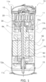
- FIG. 1 is a longitudinal sectional view of a scroll compressor 10.
- the use of expressions "upper”, “lower”, and the like indicating directions and arrangement in the scroll compressor 10 is based on FIG. 1 unless otherwise specified.
- the scroll compressor 10 is configured to compress a refrigerant in a refrigeration apparatus in implementing a refrigeration cycle for circulating the refrigerant.
- the scroll compressor 10 is installed in, for example, an outdoor unit of an air conditioning apparatus.
- the scroll compressor 10 serves as a part of a refrigerant circuit in the air conditioning apparatus.
- the scroll compressor 10 is configured to suck, compress, and discharge a refrigerant.
- a non-limiting example of the refrigerant is a hydrofluorocarbon (HFC) refrigerant such as R32. It should be noted that R32 is merely an example and a refrigerant to be compressed by the scroll compressor 10 is not limited to R32.
- HFC hydrofluorocarbon
- the scroll compressor 10 is of a fully hermetic type. In addition, the scroll compressor 10 has a symmetric wrap structure.
- the scroll compressor 10 mainly includes a casing 11, a compression mechanism 12, a motor 60, and a crank shaft 70.
- the scroll compressor 10 includes the casing 11 having a vertically elongated cylindrical shape.
- the casing 11 includes a cylindrical member 11b having upper and lower open ends, an upper cover 11a disposed on the upper open end of the cylindrical member 11b, and a lower cover 11c disposed on the lower open end of the cylindrical member 11b.
- the cylindrical member 11b, the upper cover 11a, and the lower cover 11c are fixed by welding so that a hermetic state is kept in the casing 11.
- the casing 11 accommodates the constituent components (e.g., the compression mechanism 12, the motor 60, the crank shaft 70) of the scroll compressor 10.
- the compression mechanism 12 is disposed on an upper side of an internal space.
- the compression mechanism 12 includes a fixed scroll 20 (to be described later) fixed to the casing 11.
- the motor 60 is disposed below the compression mechanism 12.
- the casing 11 has an oil reservoir 15 on the bottom of the internal space.
- the oil reservoir 15 stores a refrigerating machine oil for lubricating a sliding portion of the compression mechanism 12 and a sliding portion of the crank shaft 70.
- the internal space is a low-pressure space LPS into which a low-pressure gas refrigerant is sucked externally, except the upper side where the compression mechanism 12 is disposed.
- the low-pressure space LPS is a space into which the refrigerant flows from the refrigerant circuit, which includes the scroll compressor 10, of the air conditioning apparatus.
- the scroll compressor 10 is of a low-pressure shell type (also referred to as a low-pressure dome type).
- a suction pipe (not illustrated) is connected to the cylindrical member 11b of the casing 11.
- a discharge pipe is connected to the upper cover 11a of the casing 11, and the compressed gas refrigerant is discharged from the casing 11 through the discharge pipe.
- the motor 60 is configured to drive a movable scroll 30 (to be described later) of the compression mechanism 12. As illustrated in FIG. 1 , the motor 60 includes a stator 61 having a ring shape, and a rotor 62.
- the stator 61 is fixed to an inner face of the cylindrical member 11b of the casing 11.
- the stator 61 has a coil wound therearound.
- the rotor 62 has a cylindrical shape.
- the rotor 62 is accommodated in the stator 61 having the ring shape, with a slight gap (an air gap) between the rotor 62 and the stator 61 such that the rotor 62 is rotatable.
- the rotor 62 has a hollow portion into which the crank shaft 70 is inserted.
- the rotor 62 is coupled to the movable scroll 30 via the crank shaft 70.
- the rotor 62 rotates in accordance with startup of the motor 60 to transmit a force to the movable scroll 30 coupled thereto via the crank shaft 70.
- the movable scroll 30 thus swirls.
- the crank shaft 70 extends up and down in the casing 11.
- the crank shaft 70 couples the rotor 62 of the motor 60 to the movable scroll 30 (to be described later) of the compression mechanism 12.
- the crank shaft 70 transmits a driving force of the motor 60 to the movable scroll 30.
- the crank shaft 70 mainly includes an eccentric portion 71 and a main shaft 72.
- the eccentric portion 71 is disposed on an upper end of the main shaft 72.
- the eccentric portion 71 has a center axis that is eccentric relative to a center axis of the main shaft 72.
- the center axis of the main shaft 72 corresponds to a rotation axis RA of the crank shaft 70.
- the eccentric portion 71 is inserted in a bearing metal in a boss portion 33 (see FIG. 3B ) of the movable scroll 30.
- the center axis of the eccentric portion 71 passes the center of the movable scroll 30 with the eccentric portion 71 inserted in the boss portion 33 and the movable scroll 30 coupled to the crank shaft 70.
- the main shaft 72 is supported by an upper bearing 72a and a lower bearing 72b in a rotatable manner.
- the main shaft 72 between the upper bearing 72a and the lower bearing 72b is inserted through and coupled to the rotor 62 of the motor 60.
- the crank shaft 70 has therein an oil passage (not illustrated).
- the refrigerating machine oil in the oil reservoir 15 is pumped up by a pump disposed on a lower end of the crank shaft 70.
- the refrigerating machine oil thus pumped up is then supplied to a sliding portion of each component in the casing 11.
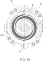
- the compression mechanism 12 mainly includes the fixed scroll 20, the movable scroll 30, and an Oldham coupling. As illustrated in, for example, FIGS. 4B and 4E , the movable scroll 30 and the fixed scroll 20 define, in combination, a first compression chamber A and a second compression chamber B.
- the compression mechanism 12 compresses the refrigerant in the first compression chamber A and the second compression chamber B, and discharges the refrigerant thus compressed.
- the compression mechanism 12 has a symmetric wrap structure. As illustrated in, for example, FIG. 4E , in the symmetric wrap structure of the compression mechanism 12, the first compression chamber A and the second compression chamber B are defined in a point symmetric state.
- the first compression chamber A is surrounded with and defined by an outer peripheral face 32a of a movable-side wrap 32 of the movable scroll 30 (to be described later) and an inner peripheral face 22b of a fixed-side wrap 22 of the fixed scroll 20 (to be described later), as seen in plan view.
- the second compression chamber B is surrounded with and defined by an inner peripheral face 32b of the movable-side wrap 32 and an outer peripheral face 22a of the fixed-side wrap 22, as seen in plan view.
- the movable-side wrap 32 is identical in winding end angle to the fixed-side wrap 22.
- the Oldham coupling is disposed below the movable scroll 30.
- the Oldham coupling is configured to restrict rotation of the movable scroll 30, thereby causing the movable scroll 30 to revolve with respect to the fixed scroll 20.
- the fixed scroll 20 includes a fixed-side flat plate 21 having a disk shape and the fixed-side wrap 22.
- the fixed-side wrap 22 extends downward from a front face 21a of the fixed-side flat plate 21 along the rotation axis RA.
- the fixed-side wrap 22 has a spiral shape as seen in plan view, and this spiral shape extends from a winding start portion 22d near a center of the fixed scroll 20 to a winding end portion 22e on an outer periphery of the fixed scroll 20.
- the fixed-side wrap 22 has a spiral shape drawn with, for example, an involute curve.
- the inner peripheral face 22b of the fixed-side wrap 22 continuously extends from the winding start portion 22d of the fixed-side wrap 22 to the winding end portion 22e of the fixed-side wrap 22.
- the winding start portion 22d of the fixed-side wrap 22 is located closer to the center 22c of the fixed-side wrap 22.
- the winding end portion 22e of the fixed-side wrap 22 is located farther from the center 22c of the fixed-side wrap 22.
- the fixed-side wrap 22 is combined with the movable-side wrap 32 of the movable scroll 30 (to be described later) to define the first and second compression chambers A and B. As illustrated in FIG.
- the fixed scroll 20 and the movable scroll 30 are combined with each other with the front face 21a of the fixed-side flat plate 21 disposed opposite a front face 31a of the movable-side flat plate 31, to thereby define the first and second compression chambers A and B surrounded with the fixed-side flat plate 21, the fixed-side wrap 22, the movable-side wrap 32, and the movable-side flat plate 31 of the movable scroll 30 to be described later.
- the movable scroll 30 swirls with respect to the fixed scroll 20
- the refrigerant which has flowed into the first and second compression chambers A and B from the low-pressure space LPS illustrated in FIG. 1 , is compressed as the refrigerant approaches the center of the fixed scroll 20 in the first and second compression chambers A and B.
- the pressure of the refrigerant is thus increased.
- the fixed-side flat plate 21 has, in its substantial center, a discharge port 21b through which the refrigerant compressed by the compression mechanism 12 is discharged.
- the discharge port 21b extends through the fixed-side flat plate 21 in a thickness direction (an up-and-down direction).
- the discharge port 21b communicates with the first and second compression chambers A and B at the center of the compression mechanism 12.
- the compression mechanism 12 also includes a discharge valve disposed above the fixed-side flat plate 21 and configured to open and close the discharge port 21b.
- the fixed scroll 20 has a first passage 41 for guiding the refrigerant in the low-pressure space LPS, to the first and second compression chambers A and B.
- the first passage 41 is a hole (an opening) bored in the fixed-side flat plate 21.
- the fixed scroll 20 also has on its outer periphery a wall 23 that does not define the first and second compression chambers.
- the wall 23 has an inner face 23a that is contiguous with the inner peripheral face 22b of the winding end portion 22e of the fixed-side wrap 22. As illustrated in, for example, FIG. 4B , the inner face 23a is opposite the outer peripheral face 32a, which does not define the first and second compression chambers, of the movable-side wrap 32 of the movable scroll 30.
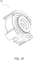
- the movable scroll 30 mainly includes the movable-side flat plate 31, the movable-side wrap 32, and the boss portion 33 extending downward from a rear face (a lower face) of the movable-side flat plate 31.
- a chip seal may be provided between a blade end (an upper end) of the movable-side wrap 32 and the front face 21a of the fixed-side flat plate 21.
- the movable-side flat plate 31 has the front face (the upper face) 31a that is opposite the front face 21a of the fixed-side flat plate 21.
- the movable-side wrap 32 extends upward from the front face 31a of the movable-side flat plate 31 along the rotation axis RA.
- the movable-side wrap 32 has a spiral shape as seen in plan view, and this spiral shape extends from a winding start portion 32d near a center 32c of the movable scroll 30 to a winding end portion 32e on an outer periphery of the movable scroll 30.
- the movable-side wrap 32 has a spiral shape drawn with, for example, an involute curve.
- the center 32c of the movable scroll 30 corresponds to the center of a base circle drawn with an involute curve defining the shape of the movable-side wrap 32.
- the center 32c of the movable scroll 30 also corresponds to a point through which the center axis of the eccentric portion 71 of the crank shaft 70 inserted in the boss portion 33 passes.
- the outer peripheral face 32a of the movable-side wrap 32 continuously extends from the winding start portion 32d of the movable-side wrap 32 to the winding end portion 32e of the movable-side wrap 32.
- the winding start portion 32d of the movable-side wrap 32 is located closer to the center 32c of the movable-side wrap 32.
- the winding end portion 32e of the movable-side wrap 32 is located farther from the center 32c of the movable-side wrap 32.
- the movable-side flat plate 31 has an outer edge 31b that is substantially coincident with a virtual circle VC as seen in the direction of the rotation axis RA.
- the virtual circle VC is a circle in virtual plan view, and the outer edge 31b of the movable-side flat plate 31 is coincident with the virtual circle VC by 50% or more.
- the movable scroll 30 has a cutout serving as a second passage 42 to be described later.
- the cutout serving as the second passage 42 extends inward with respect to the virtual circle VC.
- the second passage 42 is therefore inevitably located inside the virtual circle VC.
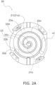
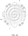
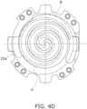
- FIGS. 4A and 4B each illustrate the fixed scroll 20 and the movable scroll 30 that are combined with each other.
- FIG. 4A is a front view of the fixed scroll 20 and the movable scroll 30 with the fixed-side wrap 22 engaged with the movable-side wrap 32.
- FIG. 4B is a plan view of the fixed scroll 20 and the movable scroll 30 at a height position IV-B in FIG. 4A , illustrating the first and second compression chambers A and B and the refrigerant guide passages (i.e., the first passage 41 and the second passage 42) defined by the fixed scroll 20 and the movable scroll 30 at a certain timing.
- FIGS. 4A to 4E as well as FIGS.
- a solid line indicates the fixed scroll 20 and a chain double-dashed line indicates the movable scroll 30 for ease of the distinction between the fixed scroll 20 and the movable scroll 30.
- a bold arrow indicates a flow of the gas refrigerant into the first and second compression chambers A and B, for ease of the understanding.
- the first compression chamber A is defined by the front face 21a of the fixed-side flat plate 21, the front face 31a of the movable-side flat plate 31, the inner peripheral face 22b of the fixed-side wrap 22, and the outer peripheral face 32a of the movable-side wrap 32.
- the second compression chamber B is defined by the front face 21a of the fixed-side flat plate 21, the front face 31a of the movable-side flat plate 31, the outer peripheral face 22a of the fixed-side wrap 22, and the inner peripheral face 32b of the movable-side wrap 32.
- the first compression chamber A has an inlet A1 corresponding to a gap (a first gap G1) between the winding end portion 22e of the fixed-side wrap 22 and the outer peripheral face 32a of the movable-side wrap 32.
- the first gap G1 has an area that increases and decreases in accordance with swirling of the movable scroll 30.
- the fixed scroll 20 has the above-mentioned first passage 41.
- the first passage 41 is a refrigerant flow path for guiding the gas refrigerant sucked externally, to the first compression chamber A and the second compression chamber B.
- the first passage 41 has a flow path area that does not change so much even in the state in which the fixed scroll 20 is combined with the movable scroll 30.
- the first passage 41 therefore guides a large amount of the gas refrigerant to a space around the winding end portion 32e of the movable-side wrap 32.
- the first passage 41 allows the refrigerant from the low-pressure space LPS to flow into the space around the winding end portion 32e of the movable-side wrap 32 with almost no resistance.
- the movable scroll 30 has the second passage 42.
- the second passage 42 is a flow path for guiding the gas refrigerant sucked into the low-pressure space LPS externally, to the first compression chamber A.
- the second passage 42 corresponds to a region located inward of the inner face 23a of the wall 23 of the fixed scroll 20 and outward of an outer face of the cutout portion of the movable-side flat plate 31 of the movable scroll 30 in the state in which the movable scroll 30 is combined with the fixed scroll 20.
- the second passage 42 is equal in area to the region located inward of the inner face 23a of the wall 23 of the fixed scroll 20 and outward of the outer face of the cutout portion of the movable-side flat plate 31 of the movable scroll 30. If the movable-side flat plate 31 of the movable scroll 30 has no cutout portion, the second passage 42 is not provided. Since the movable-side flat plate 31 of the movable scroll 30 has the cutout portion corresponding to the second passage 42 located inside the virtual circle VC, the second passage 42 emerges in the state in which the movable scroll 30 is combined with the fixed scroll 20.
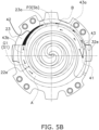
- the second passage 42 in FIG. 5B is a passage that emerges when the position of the movable scroll 30 relative to the fixed scroll 20 is in a predetermined state.
- the shape and area of the passage in plan view change as illustrated in, for example, FIGS. 4C and 4D .
- the gas refrigerant which has passed through the second passage 42 enters a third passage 43 to be described later, and merges with the gas refrigerant which has flowed through another passage.
- the merged gas refrigerant then flows into the first compression chamber A.
- the third passage 43 is defined between the inlet A1 of the first compression chamber A and the first passage 41 in the fixed scroll 20.
- the third passage 43 is a flow path for guiding the gas refrigerant sucked into the low-pressure space LPS externally, to the first compression chamber A.
- the third passage 43 is surrounded with the front face 21a of the fixed-side flat plate 21, the front face 31a of the movable-side flat plate 31, the outer peripheral face 32a, which does not define the first and second compression chambers, of the movable-side wrap 32, and the inner face 23a of the wall 23 of the fixed scroll 20.
- the third passage 43 includes a downstream portion 43b and an upstream portion 43a.
- the downstream portion 43b is located near the inlet A1 of the first compression chamber A.
- the upstream portion 43a is located near the first passage 41 in the fixed scroll 20.
- the gas refrigerant which has passed through the first passage 41 flows into the first compression chamber A via the upstream portion 43a and downstream portion 43b of the third passage 43.
- the gas refrigerant which has passed through the second passage 42 flows into the first compression chamber A via the downstream portion 43b of the third passage 43.
- the gas refrigerant flows into the third passage 43 via the second gap G2 defined in an angle range from P1 to P2 in FIG. 5A .
- the movable-side flat plate 31 is opposite an end face 23b of the wall 23 of the fixed scroll 20.
- a gap i.e., the second gap G2 is defined between the movable-side flat plate 31 and the end face 23b of the wall 23 of the fixed scroll 20 in the direction of the rotation axis RA.
- the gas refrigerant is guided by the second gap G2 to the third passage 43 without passing through the first passage 41 and the second passage 42.
- the second gap G2 extends to a position ahead of the inlet A1 of the first compression chamber A of the third passage 43; however, the second gap G2 does not extend to the region of the first compression chamber A as illustrated in FIG. 6A . This is because the second gap G2 in the region of the first compression chamber A hinders compression of the gas refrigerant.
- the first passage 41 and the second passage 42 are separated from each other as seen in the direction of the rotation axis RA. As illustrated in FIG. 4B , the first passage 41 is closer to the winding end portion 32e of the movable-side wrap 32 than to the winding end portion 22e of the fixed-side wrap 22.
- the second passage 42 in the movable scroll 30 is closer to the winding end portion 22e of the fixed-side wrap 22 than to the winding end portion 32e of the movable-side wrap 32 as seen in the direction of the rotation axis RA.
- the second passage 42 in the movable scroll 30 is located inside the virtual circle VC (i.e., located near the center 32c of the movable-side wrap 32) as seen in the direction of the rotation axis RA. In the scroll compressor 10, therefore, the second passage 42 is separated from the cylindrical member 11b of the casing 11.
- the gas refrigerant which has passed through the third passage 43 via the first passage 41, the second passage 42, and the second gap G2 flows into the first compression chamber A through the inlet A1.
- the gas refrigerant which has passed through the first passage 41 located near the second compression chamber B as seen in plan view flows into the second compression chamber B.
- the low-pressure space LPS does not communicate with the first and second compression chambers A and B in a stepwise manner (see the state illustrated in FIG. 4E ).
- the pressures in the first and second compression chambers A and B rise.
- the pressure of the refrigerant gradually rises as the refrigerant moves from each of the first and second compression chambers A and B close to the peripheral edge of the compression mechanism 12, that is, located outward of the compression mechanism 12, to each of the first and second compression chambers A and B close to the center of the compression mechanism 12, that is, located inward of the compression mechanism 12.
- the high-pressure refrigerant is obtained in the refrigeration cycle.
- the refrigerant thus compressed is discharged from the compression mechanism 12 through the discharge port 21b in the fixed-side flat plate 21.
- a scroll compressor 10 has a symmetric wrap structure and includes a fixed scroll 20, a movable scroll 30, and a crank shaft 70.
- the fixed scroll 20 includes a fixed-side flat plate 21 and a fixed-side wrap 22 having a spiral shape.
- the fixed-side wrap 22 extends downward from a front face 21a of the fixed-side flat plate 21.
- the movable scroll 30 includes a movable-side flat plate 31 and a movable-side wrap 32 having a spiral shape.
- the movable-side wrap 32 extends upward from a front face 31a of the movable-side flat plate 31.
- the crank shaft 70 is configured to rotate about a rotation axis RA and to drive the movable scroll 30.
- the fixed scroll 20 and the movable scroll 30 define a first compression chamber A surrounded with the front face 21a of the fixed-side flat plate 21, the front face 31a of the movable-side flat plate 31, an inner peripheral face 22b of the fixed-side wrap 22, and an outer peripheral face 32a of the movable-side wrap 32.
- the fixed scroll 20 and the movable scroll 30 define a second compression chamber B surrounded with the front face 21a of the fixed-side flat plate 21, the front face 31a of the movable-side flat plate 31, an outer peripheral face 22a of the fixed-side wrap 22, and an inner peripheral face 32b of the movable-side wrap 32.
- the fixed scroll 20 has a first passage 41.
- the first passage 41 is a refrigerant flow path for guiding a gas refrigerant sucked externally, to the first compression chamber A and the second compression chamber B.
- the movable scroll 30 has a second passage 42.
- the second passage 42 is a refrigerant flow path for guiding the gas refrigerant sucked externally, to the first compression chamber A.
- Each of the gas refrigerant which has passed through the first passage 41 and the gas refrigerant which has passed through the second passage 42 flows into the first compression chamber A.
- the gas refrigerant which has passed through the first passage 41 flows into the second compression chamber B.
- the gas refrigerant which has passed through the first passage 41 flows into the first compression chamber A and the second compression chamber B.
- the gas refrigerant which has passed through the second passage 42 flows into the first compression chamber A.
- the first passage 41 is provided in the fixed scroll 20.
- the second passage 42 is provided in the movable scroll 30. This configuration eliminates necessity to arrange the first passage 41 and the second passage 42 with the rotation axis RA interposed between the first passage 41 and the second passage 42. This configuration therefore improves the degree of freedom as to arrangement of the second passage 42.
- the second passage 42 is provided at the position illustrated in FIGS. 2A , 3A , and 5B . As illustrated in FIG.
- the size of the second passage 42 is determined such that the second passage 42 allows the gas refrigerant to pass therethrough so as to complement the first passage 41.
- the scroll compressor 10 therefore suppresses occurrence of a phenomenon in which the gas refrigerant flows upward at a high flow velocity on two sides (i.e., a side near the first passage 41 and its opposite side) of the low-pressure space LPS illustrated in FIG. 1 .
- the scroll compressor 10 thus suppresses occurrence of an oil loss phenomenon.
- the second passage 42 in the movable scroll 30 is closer to a winding end portion 22e of the fixed-side wrap 22 than to a winding end portion 32e of the movable-side wrap 32 as seen in the direction of the rotation axis RA.
- the third passage 43 is long and has a narrow flow path area in places, which tends to result in shortage of the amount of the gas refrigerant flowing into the first compression chamber A.
- the second passage 42 for compensating for this shortage is located closer to the winding end portion 22e of the fixed-side wrap 22 than to the winding end portion 32e of the movable-side wrap 32.
- the scroll compressor 10 therefore reduces a difference between the amount of the gas refrigerant flowing into the first compression chamber A and the amount of the gas refrigerant flowing into the second compression chamber B.
- the second passage 42 in FIG. 5B is a passage that emerges when the position of the movable scroll 30 relative to the fixed scroll 20 is in a predetermined state.
- the shape and area of the passage in plan view change as illustrated in, for example, FIGS. 4C and 4D .
- the second passage 42 for guiding the gas refrigerant in the low-pressure space LPS to the first compression chamber A is always closer to the winding end portion 22e of the fixed-side wrap 22 than to the winding end portion 32e of the movable-side wrap 32, irrespective of the position of the movable scroll 30 relative to the fixed scroll 20.
- the second passage 42 corresponds to a region located inward of an inner face 23a of a wall 23 of the fixed scroll 20 and outward of an outer face of a cutout portion of the movable-side flat plate 31 of the movable scroll 30 as seen in the direction of the rotation axis RA.
- a center of the flow path area as seen in the direction of the rotation axis RA i.e., a center of gravity in sectional view
- the movable-side flat plate 31 has an outer edge 31b that is substantially coincident with a virtual circle VC as seen in the direction of the rotation axis RA.
- the virtual circle VC is a circle in virtual plan view, and the outer edge 31b of the movable-side flat plate 31 is coincident with the virtual circle VC by 50% or more.
- the second passage 42 in the movable scroll 30 is located inside the virtual circle VC (i.e., located near a center 32c of the movable-side wrap 32) as seen in the direction of the rotation axis RA.
- the second passage 42 is separated from a cylindrical member 11b of a casing 11. This configuration suppresses occurrence of a phenomenon in which the refrigerating machine oil flowing downward along an inner face of the cylindrical member 11b of the casing 11 curls upward due to the gas refrigerant flowing into the second passage 42.
- the first passage 41 in the fixed scroll 20 is a hole (an opening) bored in the fixed-side flat plate 21. Therefore, the first passage 41 is formed in the fixed scroll 20 with ease by casting or machining.
- the first compression chamber A has an inlet A1 corresponding to a gap (a first gap G1) between the winding end portion 22e of the fixed-side wrap 22 and the outer peripheral face 32a of the movable-side wrap 32.
- the first gap G1 has an area that increases and decreases in accordance with swirling of the movable scroll 30.
- the fixed scroll 20 and the movable scroll 30 define a third passage 43 between the inlet A1 of the first compression chamber A and the first passage 41 in the fixed scroll 20.
- the third passage 43 is a gas refrigerant flow path for guiding the gas refrigerant sucked externally, to the first compression chamber A. As illustrated in FIGS.
- the third passage 43 is surrounded with the front face 21a of the fixed-side flat plate 21, the front face 31a of the movable-side flat plate 31, the outer peripheral face 32a, which does not define the first and second compression chambers, of the movable-side wrap 32, and the inner face 23a of the wall 23 of the fixed scroll 20.
- the third passage 43 includes a downstream portion 43b and an upstream portion 43a.
- the downstream portion 43b is located near the inlet A1 of the first compression chamber A.
- the upstream portion 43a is located near the first passage 41 in the fixed scroll 20.
- the gas refrigerant which has passed through the first passage 41 flows into the first compression chamber A via the upstream portion 43a and downstream portion 43b of the third passage 43.
- the gas refrigerant which has passed through the second passage 42 flows into the first compression chamber A via the downstream portion 43b of the third passage 43.
- the third passage 43 allows a part of the gas refrigerant which has passed through the first passage 41 in the fixed scroll 20 to be guided to the first compression chamber A rather than the second compression chamber B. Even in such a scroll compressor 10 that a second passage 42 is smaller than a first passage 41 and a small amount of gas refrigerant flows into the second passage 42, this configuration reduces a difference between an amount of the gas refrigerant flowing into the first compression chamber A and an amount of the gas refrigerant flowing into the second compression chamber B.
- the movable-side flat plate 31 and an end face 23b of the wall 23 of the fixed scroll 20 are disposed opposite each other with a gap (a second gap G2) interposed between the movable-side flat plate 31 and the end face 23b of the wall 23 of the fixed scroll 20 in the direction of the rotation axis RA.
- the gas refrigerant is guided by the second gap G2 to the third passage 43 without passing through the first passage 41 and the second passage 42.
- the sectional areas Sa, Sb, and Sc of the flow paths via which the gas refrigerant flows into the first compression chamber A are determined such that the inequality described above is established.
- This configuration therefore secures an amount of the gas refrigerant flowing into the first compression chamber A.
- this configuration enables a considerable reduction of the difference between the amount of the gas refrigerant flowing into the first compression chamber A and the amount of the gas refrigerant flowing into the second compression chamber B.
- the first passage 41 and the second passage 42 are separated from each other as seen in the direction of the rotation axis RA.
- the first passage 41 is closer to the winding end portion 32e of the movable-side wrap 32 than to the winding end portion 22e of the fixed-side wrap 22.
- the first passage 41 is located near the winding end portion 32e of the movable-side wrap 32.
- This configuration therefore reduces a pressure loss of the gas refrigerant flowing into the second compression chamber B via the first passage 41.
- each of the gas refrigerant which has passed through the first passage 41 and the gas refrigerant which has passed through the second passage 42 flows into the first compression chamber A. This configuration therefore secures the amount of the gas refrigerant flowing into the first compression chamber A even when the pressure loss of the gas refrigerant increases.
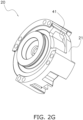
- the first passage 41 in the fixed scroll 20 is a hole as illustrated in FIGS. 2A and 2G .
- the first passage 41 may be a cutout rather than a hole.
- the movable-side flat plate 31 of the movable scroll 30 has the cutout serving as the second passage 42, as illustrated in FIG. 3A .
- the movable-side flat plate 31 of the movable scroll 30 may have an elongated opening rather than a cutout.
- Patent Literature 1 JP 2018-009537 A
Landscapes
- Engineering & Computer Science (AREA)
- Mechanical Engineering (AREA)
- General Engineering & Computer Science (AREA)
- Rotary Pumps (AREA)
- Applications Or Details Of Rotary Compressors (AREA)
- Structures Of Non-Positive Displacement Pumps (AREA)
- Compressors, Vaccum Pumps And Other Relevant Systems (AREA)
Claims (7)
- Compresseur à spirale (10), comprenant :une spirale fixe (20), incluantune plaque plate côté fixe (21) etune enveloppe côté fixe (22) ayant une forme de spirale et se prolongeant à partir d'une face avant (21a) de la plaque plate côté fixe ;une spirale mobile (30), incluantune plaque plate côté mobile (31) etune enveloppe côté mobile (32) ayant une forme de spirale et se prolongeant à partir d'une face avant (31a) de la plaque plate côté mobile ;un arbre à vilebrequin (70) configuré pour tourner autour d'un axe de rotation (RA) et pour entraîner la spirale mobile ;un moteur (60) configuré pour faire tourner l'arbre à vilebrequin (70) ; etun carter (11) comportant un espace interne étant défini pour loger la spirale fixe, la spirale mobile, l'arbre à vilebrequin et le moteur, dans lequel le carter inclut un réservoir d'huile (15) où une huile de la machine frigorifique est retenue, le réservoir d'huile étant situé sur un fond de l'espace interne, dans lequel le carter comporte un endroit où le moteur est logé, l'endroit servant d'espace à basse pression (LPS) dans lequel un réfrigérant gazeux à basse pression est aspiré extérieurement,dans lequella spirale fixe et la spirale mobile définissent une première chambre de compression (A) entourée de la face avant de la plaque plate côté fixe, de la face avant de la plaque plate côté mobile, d'une face périphérique intérieure (22b) de l'enveloppe côté fixe et d'une face périphérique extérieure (32a) de l'enveloppe côté mobile,la spirale fixe et la spirale mobile définissent une deuxième chambre de compression (B) entourée par la face avant de la plaque plate côté fixe, la face avant de la plaque plate côté mobile, une face périphérique extérieure (22a) de l'enveloppe côté fixe et une face périphérique intérieure (32b) de l'enveloppe côté mobile,le compresseur à spirale (10) comporte une structure d'enveloppe symétrique de sorte que la première chambre de compression (A) et la deuxième chambre de compression (B) sont définies dans un état de symétrie ponctuelle, la spirale fixe et la spirale mobile sont disposées sur une partie supérieure de l'espace interne du carter (11) et caractérisé en ce quela spirale fixe comporte un premier passage (41) pour guider un gaz réfrigérant dans l'espace à basse pression (LPS) vers la première chambre de compression et la deuxième chambre de compression,la spirale mobile comporte un deuxième passage (42) pour guider le réfrigérant gazeux dans l'espace à basse pression (LPS) vers la première chambre de compression,le réfrigérant gazeux ayant traversé le premier passage et le réfrigérant gazeux ayant traversé le deuxième passage s'écoulent chacun dans la première chambre de compression, etle réfrigérant gazeux ayant traversé le premier passage s'écoule dans la deuxième chambre de compression.
- Compresseur à spirale selon la revendication 1, dans lequell'enveloppe côté fixe et l'enveloppe côté mobile se prolongent dans une direction de l'axe de rotation (RA), la face périphérique intérieure (22b) de l'enveloppe côté fixe se prolonge continuellement d'une partie initiale d'enroulement (22d) de l'enveloppe côté fixe, la partie initiale d'enroulement étant plus proche d'un centre (22c) de l'enveloppe côté fixe, jusqu'à une partie terminale d'enroulement (22e) de l'enveloppe côté fixe, la partie terminale d'enroulement étant plus éloignée du centre de l'enveloppe côté fixe,la face périphérique extérieure (32a) de l'enveloppe côté mobile se prolonge continuellement à partir d'une partie initiale d'enroulement (32d) de l'enveloppe côté mobile, la partie initiale d'enroulement étant plus proche d'un centre (32c) de l'enveloppe côté mobile, jusqu'à une partie terminale d'enroulement (32e) de l'enveloppe côté mobile, la partie terminale d'enroulement étant plus éloignée du centre de l'enveloppe côté mobile, etle deuxième passage (42) dans la spirale mobile est plus proche de la partie terminale d'enroulement (22e) de l'enveloppe côté fixe que de la partie terminale d'enroulement (32e) de l'enveloppe côté mobile, tel que vu dans la direction de l'axe de rotation (RA).
- Compresseur à spirale selon la revendication 1 ou 2, dans lequell'enveloppe côté fixe et l'enveloppe côté mobile se prolongent dans une direction de l'axe de rotation (RA), la plaque plate côté mobile comporte un bord extérieur (31b) qui coïncide avec un cercle virtuel (VC) de 50 % ou plus tel que vu dans la direction de l'axe de rotation (RA), etle deuxième passage (42) dans la spirale mobile est situé à l'intérieur du cercle virtuel (VC) tel que vu dans la direction de l'axe de rotation (RA).
- Compresseur à spirale selon l'une quelconque des revendications 1 à 3, dans lequel le premier passage (41) dans la spirale fixe comprend un trou ou une découpe.
- Compresseur à spirale selon la revendication 2, dans lequella première chambre de compression (A) comporte une entrée (A1) correspondant à un premier espacement (G1) entre la partie terminale d'enroulement (22e) de l'enveloppe côté fixe et la face périphérique extérieure (32a) de l'enveloppe côté mobile,le premier espacement comporte une surface qui augmente et diminue selon le tourbillonnement de la spirale mobile,la spirale fixe inclut de plus une paroi (23) qui ne définit pas les première et deuxième chambres de compression,la spirale fixe et la spirale mobile définissent un troisième passage (43) pour guider le gaz réfrigérant aspiré extérieurement vers la première chambre de compression (A), le troisième passage étant situé entre l'entrée (A1) de la première chambre de compression (A) et le premier passage (41) dans la spirale fixe,le troisième passage (43) est entouré par la face avant de la plaque plate côté fixe, la face avant de la plaque plate côté mobile, la face périphérique extérieure (32a), qui ne définit pas les première et deuxième chambres de compression, de l'enveloppe côté mobile, et une face intérieure (23a) de la paroi (23) de la spirale fixe,le troisième passage (43) inclut une partie en aval (43b) située près de l'entrée (A1) de la première chambre de compression (A), etune partie en amont (43a) située près du premier passage (41) dans la spirale fixe,le gaz réfrigérant qui a traversé le premier passage (41) s'écoule dans la première chambre de compression (A) via la partie en amont (43a) et la partie en aval (43b) du troisième passage (43), etle gaz réfrigérant qui a traversé le deuxième passage (42) s'écoule dans la première chambre de compression (A) via la partie en aval (43b) du troisième passage (43) .
- Compresseur à spirale selon la revendication 5, dans lequella plaque plate côté mobile (31) et la face terminale (23b) de la paroi (23) de la spirale fixe sont disposées l'une en face de l'autre avec un deuxième espacement (G2) interposé entre la plaque plate côté mobile (31) et la face terminale (23b) de la paroi (23) de la spirale fixe dans la direction de l'axe de rotation (RA),le gaz réfrigérant est guidé par le deuxième espacement (G2) vers le troisième passage (43) sans passer par le premier passage (41) et le deuxième passage (42), et une inégalité représentée par S1 < Sa + Sb + Sc est établie,
oùS1 représente une surface de section du premier espacement (G1),Sa représente une surface de section du deuxième passage (42) en correspondance d'une limite entre le deuxième passage (42) et le troisième passage (43),Sb représente une surface de section d'une partie (P3) comportant une surface de passage minimale dans le troisième passage (43), etSc représente une surface de section du deuxième espacement (G2). - Compresseur à spirale selon la revendication 2, dans lequelle premier passage (41) et le deuxième passage (42) sont séparés l'un de l'autre dans la direction de l'axe de rotation (RA), etle premier passage (41) est plus proche de la partie terminale d'enroulement (32e) de l'enveloppe côté mobile que de la partie terminale d'enroulement (22e) de l'enveloppe côté fixe.
Applications Claiming Priority (2)
| Application Number | Priority Date | Filing Date | Title |
|---|---|---|---|
| JP2019143730A JP6874795B2 (ja) | 2019-08-05 | 2019-08-05 | スクロール圧縮機 |
| PCT/JP2020/029890 WO2021025033A1 (fr) | 2019-08-05 | 2020-08-04 | Compresseur à spirale |
Publications (3)
| Publication Number | Publication Date |
|---|---|
| EP3985256A1 EP3985256A1 (fr) | 2022-04-20 |
| EP3985256A4 EP3985256A4 (fr) | 2022-08-17 |
| EP3985256B1 true EP3985256B1 (fr) | 2023-09-13 |
Family
ID=74503000
Family Applications (1)
| Application Number | Title | Priority Date | Filing Date |
|---|---|---|---|
| EP20850952.1A Active EP3985256B1 (fr) | 2019-08-05 | 2020-08-04 | Compresseur à spirale |
Country Status (6)
| Country | Link |
|---|---|
| US (1) | US11493041B2 (fr) |
| EP (1) | EP3985256B1 (fr) |
| JP (1) | JP6874795B2 (fr) |
| CN (1) | CN114222861B (fr) |
| ES (1) | ES2966984T3 (fr) |
| WO (1) | WO2021025033A1 (fr) |
Families Citing this family (1)
| Publication number | Priority date | Publication date | Assignee | Title |
|---|---|---|---|---|
| CN116608124B (zh) * | 2023-05-24 | 2026-02-27 | 广东吉洪茂医疗科技有限公司 | 一种无油涡旋压缩机的吸气结构及一种无油涡旋压缩机 |
Family Cites Families (17)
| Publication number | Priority date | Publication date | Assignee | Title |
|---|---|---|---|---|
| JPS5844402U (ja) * | 1981-09-19 | 1983-03-25 | トキコ株式会社 | スクロ−ル式流体機械 |
| JPS61197786A (ja) * | 1985-02-28 | 1986-09-02 | Toshiba Corp | スクロ−ル形圧縮機 |
| JPH07117055B2 (ja) * | 1986-02-10 | 1995-12-18 | 松下冷機株式会社 | スクロ−ル型圧縮機 |
| JPH0697036B2 (ja) | 1986-05-30 | 1994-11-30 | 松下電器産業株式会社 | 電動圧縮機 |
| JPH04262085A (ja) * | 1991-01-21 | 1992-09-17 | Mitsubishi Electric Corp | スクロール型圧縮機 |
| JP3207308B2 (ja) * | 1993-12-16 | 2001-09-10 | 株式会社デンソー | スクロール型圧縮機 |
| JPH1182336A (ja) * | 1997-09-04 | 1999-03-26 | Yamaha Motor Co Ltd | スクロールコンプレッサ |
| KR100920980B1 (ko) * | 2008-02-19 | 2009-10-09 | 엘지전자 주식회사 | 스크롤 압축기의 용량 가변장치 |
| JP5719685B2 (ja) * | 2011-05-17 | 2015-05-20 | 日立アプライアンス株式会社 | ヘリウム用密閉形スクロール圧縮機 |
| JP5762352B2 (ja) * | 2012-04-24 | 2015-08-12 | 株式会社日本自動車部品総合研究所 | スクロール圧縮機 |
| JP6235857B2 (ja) * | 2013-10-18 | 2017-11-22 | 株式会社Soken | スクロール型圧縮機 |
| US9638191B2 (en) * | 2014-08-04 | 2017-05-02 | Emerson Climate Technologies, Inc. | Capacity modulated scroll compressor |
| JP6137166B2 (ja) * | 2014-12-26 | 2017-05-31 | ダイキン工業株式会社 | スクロール圧縮機および冷凍装置 |
| KR102487906B1 (ko) * | 2016-04-26 | 2023-01-12 | 엘지전자 주식회사 | 스크롤 압축기 |
| JP2018009537A (ja) | 2016-07-14 | 2018-01-18 | 三菱電機株式会社 | スクロール圧縮機および冷凍サイクル装置 |
| WO2019150421A1 (fr) * | 2018-01-30 | 2019-08-08 | 三菱電機株式会社 | Compresseur à spirale |
| KR102191126B1 (ko) * | 2019-03-21 | 2020-12-16 | 엘지전자 주식회사 | 전동식 압축기 |
-
2019
- 2019-08-05 JP JP2019143730A patent/JP6874795B2/ja active Active
-
2020
- 2020-08-04 CN CN202080054191.3A patent/CN114222861B/zh active Active
- 2020-08-04 WO PCT/JP2020/029890 patent/WO2021025033A1/fr not_active Ceased
- 2020-08-04 ES ES20850952T patent/ES2966984T3/es active Active
- 2020-08-04 EP EP20850952.1A patent/EP3985256B1/fr active Active
-
2022
- 2022-01-18 US US17/578,209 patent/US11493041B2/en active Active
Also Published As
| Publication number | Publication date |
|---|---|
| ES2966984T3 (es) | 2024-04-25 |
| JP2021025459A (ja) | 2021-02-22 |
| CN114222861A (zh) | 2022-03-22 |
| EP3985256A1 (fr) | 2022-04-20 |
| WO2021025033A1 (fr) | 2021-02-11 |
| JP6874795B2 (ja) | 2021-05-19 |
| US20220136503A1 (en) | 2022-05-05 |
| CN114222861B (zh) | 2023-08-22 |
| US11493041B2 (en) | 2022-11-08 |
| EP3985256A4 (fr) | 2022-08-17 |
Similar Documents
| Publication | Publication Date | Title |
|---|---|---|
| JP5285988B2 (ja) | 横型スクロール圧縮機 | |
| JP6300829B2 (ja) | 回転式圧縮機 | |
| EP2312164B1 (fr) | Compresseur à volutes | |
| EP2759708B1 (fr) | Compresseur à spirale | |
| KR20130014337A (ko) | 로터리 2단 압축기 | |
| KR101361346B1 (ko) | 스크롤 압축기 | |
| CN115552123A (zh) | 横卧型旋转式压缩机 | |
| JP2020153339A (ja) | スクロール圧縮機 | |
| US20060177335A1 (en) | Low-pressure type orbiting vane compressor | |
| CN110291292A (zh) | 压缩机 | |
| EP3985256B1 (fr) | Compresseur à spirale | |
| EP2236828B1 (fr) | Compresseur à spirale | |
| WO2018008368A1 (fr) | Compresseur | |
| CN111182975B (zh) | 油分离器 | |
| EP2412980B1 (fr) | Compresseur monovis | |
| JP6074620B2 (ja) | 圧縮機 | |
| EP4474651B1 (fr) | Compresseur rotatif et appareil de réfrigération | |
| JP2009167983A (ja) | スクロール圧縮機 | |
| CN116075637B (zh) | 压缩机 | |
| EP4286689B1 (fr) | Compresseur à spirales | |
| US11788531B2 (en) | Scroll compressor | |
| JP2010084707A (ja) | 圧縮機 | |
| JPWO2018020992A1 (ja) | 圧縮機 | |
| WO2015092571A1 (fr) | Compresseur à volutes | |
| JP2011085039A (ja) | 高圧密閉型圧縮機 |
Legal Events
| Date | Code | Title | Description |
|---|---|---|---|
| STAA | Information on the status of an ep patent application or granted ep patent |
Free format text: STATUS: THE INTERNATIONAL PUBLICATION HAS BEEN MADE |
|
| PUAI | Public reference made under article 153(3) epc to a published international application that has entered the european phase |
Free format text: ORIGINAL CODE: 0009012 |
|
| STAA | Information on the status of an ep patent application or granted ep patent |
Free format text: STATUS: REQUEST FOR EXAMINATION WAS MADE |
|
| 17P | Request for examination filed |
Effective date: 20220112 |
|
| AK | Designated contracting states |
Kind code of ref document: A1 Designated state(s): AL AT BE BG CH CY CZ DE DK EE ES FI FR GB GR HR HU IE IS IT LI LT LU LV MC MK MT NL NO PL PT RO RS SE SI SK SM TR |
|
| A4 | Supplementary search report drawn up and despatched |
Effective date: 20220714 |
|
| RIC1 | Information provided on ipc code assigned before grant |
Ipc: F04C 29/12 20060101ALI20220708BHEP Ipc: F04C 18/02 20060101AFI20220708BHEP |
|
| DAV | Request for validation of the european patent (deleted) | ||
| DAX | Request for extension of the european patent (deleted) | ||
| RAP3 | Party data changed (applicant data changed or rights of an application transferred) |
Owner name: DAIKIN INDUSTRIES, LTD. |
|
| GRAP | Despatch of communication of intention to grant a patent |
Free format text: ORIGINAL CODE: EPIDOSNIGR1 |
|
| STAA | Information on the status of an ep patent application or granted ep patent |
Free format text: STATUS: GRANT OF PATENT IS INTENDED |
|
| INTG | Intention to grant announced |
Effective date: 20230512 |
|
| GRAS | Grant fee paid |
Free format text: ORIGINAL CODE: EPIDOSNIGR3 |
|
| P01 | Opt-out of the competence of the unified patent court (upc) registered |
Effective date: 20230525 |
|
| GRAA | (expected) grant |
Free format text: ORIGINAL CODE: 0009210 |
|
| STAA | Information on the status of an ep patent application or granted ep patent |
Free format text: STATUS: THE PATENT HAS BEEN GRANTED |
|
| AK | Designated contracting states |
Kind code of ref document: B1 Designated state(s): AL AT BE BG CH CY CZ DE DK EE ES FI FR GB GR HR HU IE IS IT LI LT LU LV MC MK MT NL NO PL PT RO RS SE SI SK SM TR |
|
| REG | Reference to a national code |
Ref country code: CH Ref legal event code: EP |
|
| REG | Reference to a national code |
Ref country code: DE Ref legal event code: R096 Ref document number: 602020017794 Country of ref document: DE |
|
| REG | Reference to a national code |
Ref country code: IE Ref legal event code: FG4D |
|
| REG | Reference to a national code |
Ref country code: LT Ref legal event code: MG9D |
|
| REG | Reference to a national code |
Ref country code: NL Ref legal event code: MP Effective date: 20230913 |
|
| PG25 | Lapsed in a contracting state [announced via postgrant information from national office to epo] |
Ref country code: GR Free format text: LAPSE BECAUSE OF FAILURE TO SUBMIT A TRANSLATION OF THE DESCRIPTION OR TO PAY THE FEE WITHIN THE PRESCRIBED TIME-LIMIT Effective date: 20231214 |
|
| PG25 | Lapsed in a contracting state [announced via postgrant information from national office to epo] |
Ref country code: SE Free format text: LAPSE BECAUSE OF FAILURE TO SUBMIT A TRANSLATION OF THE DESCRIPTION OR TO PAY THE FEE WITHIN THE PRESCRIBED TIME-LIMIT Effective date: 20230913 Ref country code: RS Free format text: LAPSE BECAUSE OF FAILURE TO SUBMIT A TRANSLATION OF THE DESCRIPTION OR TO PAY THE FEE WITHIN THE PRESCRIBED TIME-LIMIT Effective date: 20230913 Ref country code: NO Free format text: LAPSE BECAUSE OF FAILURE TO SUBMIT A TRANSLATION OF THE DESCRIPTION OR TO PAY THE FEE WITHIN THE PRESCRIBED TIME-LIMIT Effective date: 20231213 Ref country code: LV Free format text: LAPSE BECAUSE OF FAILURE TO SUBMIT A TRANSLATION OF THE DESCRIPTION OR TO PAY THE FEE WITHIN THE PRESCRIBED TIME-LIMIT Effective date: 20230913 Ref country code: LT Free format text: LAPSE BECAUSE OF FAILURE TO SUBMIT A TRANSLATION OF THE DESCRIPTION OR TO PAY THE FEE WITHIN THE PRESCRIBED TIME-LIMIT Effective date: 20230913 Ref country code: HR Free format text: LAPSE BECAUSE OF FAILURE TO SUBMIT A TRANSLATION OF THE DESCRIPTION OR TO PAY THE FEE WITHIN THE PRESCRIBED TIME-LIMIT Effective date: 20230913 Ref country code: GR Free format text: LAPSE BECAUSE OF FAILURE TO SUBMIT A TRANSLATION OF THE DESCRIPTION OR TO PAY THE FEE WITHIN THE PRESCRIBED TIME-LIMIT Effective date: 20231214 Ref country code: FI Free format text: LAPSE BECAUSE OF FAILURE TO SUBMIT A TRANSLATION OF THE DESCRIPTION OR TO PAY THE FEE WITHIN THE PRESCRIBED TIME-LIMIT Effective date: 20230913 |
|
| REG | Reference to a national code |
Ref country code: AT Ref legal event code: MK05 Ref document number: 1611552 Country of ref document: AT Kind code of ref document: T Effective date: 20230913 |
|
| PG25 | Lapsed in a contracting state [announced via postgrant information from national office to epo] |
Ref country code: NL Free format text: LAPSE BECAUSE OF FAILURE TO SUBMIT A TRANSLATION OF THE DESCRIPTION OR TO PAY THE FEE WITHIN THE PRESCRIBED TIME-LIMIT Effective date: 20230913 |
|
| PG25 | Lapsed in a contracting state [announced via postgrant information from national office to epo] |
Ref country code: IS Free format text: LAPSE BECAUSE OF FAILURE TO SUBMIT A TRANSLATION OF THE DESCRIPTION OR TO PAY THE FEE WITHIN THE PRESCRIBED TIME-LIMIT Effective date: 20240113 |
|
| PG25 | Lapsed in a contracting state [announced via postgrant information from national office to epo] |
Ref country code: AT Free format text: LAPSE BECAUSE OF FAILURE TO SUBMIT A TRANSLATION OF THE DESCRIPTION OR TO PAY THE FEE WITHIN THE PRESCRIBED TIME-LIMIT Effective date: 20230913 |
|
| REG | Reference to a national code |
Ref country code: ES Ref legal event code: FG2A Ref document number: 2966984 Country of ref document: ES Kind code of ref document: T3 Effective date: 20240425 |
|
| PG25 | Lapsed in a contracting state [announced via postgrant information from national office to epo] |
Ref country code: SM Free format text: LAPSE BECAUSE OF FAILURE TO SUBMIT A TRANSLATION OF THE DESCRIPTION OR TO PAY THE FEE WITHIN THE PRESCRIBED TIME-LIMIT Effective date: 20230913 Ref country code: RO Free format text: LAPSE BECAUSE OF FAILURE TO SUBMIT A TRANSLATION OF THE DESCRIPTION OR TO PAY THE FEE WITHIN THE PRESCRIBED TIME-LIMIT Effective date: 20230913 Ref country code: IS Free format text: LAPSE BECAUSE OF FAILURE TO SUBMIT A TRANSLATION OF THE DESCRIPTION OR TO PAY THE FEE WITHIN THE PRESCRIBED TIME-LIMIT Effective date: 20240113 Ref country code: EE Free format text: LAPSE BECAUSE OF FAILURE TO SUBMIT A TRANSLATION OF THE DESCRIPTION OR TO PAY THE FEE WITHIN THE PRESCRIBED TIME-LIMIT Effective date: 20230913 Ref country code: CZ Free format text: LAPSE BECAUSE OF FAILURE TO SUBMIT A TRANSLATION OF THE DESCRIPTION OR TO PAY THE FEE WITHIN THE PRESCRIBED TIME-LIMIT Effective date: 20230913 Ref country code: AT Free format text: LAPSE BECAUSE OF FAILURE TO SUBMIT A TRANSLATION OF THE DESCRIPTION OR TO PAY THE FEE WITHIN THE PRESCRIBED TIME-LIMIT Effective date: 20230913 Ref country code: SK Free format text: LAPSE BECAUSE OF FAILURE TO SUBMIT A TRANSLATION OF THE DESCRIPTION OR TO PAY THE FEE WITHIN THE PRESCRIBED TIME-LIMIT Effective date: 20230913 Ref country code: PT Free format text: LAPSE BECAUSE OF FAILURE TO SUBMIT A TRANSLATION OF THE DESCRIPTION OR TO PAY THE FEE WITHIN THE PRESCRIBED TIME-LIMIT Effective date: 20240115 |
|
| PG25 | Lapsed in a contracting state [announced via postgrant information from national office to epo] |
Ref country code: PL Free format text: LAPSE BECAUSE OF FAILURE TO SUBMIT A TRANSLATION OF THE DESCRIPTION OR TO PAY THE FEE WITHIN THE PRESCRIBED TIME-LIMIT Effective date: 20230913 |
|
| REG | Reference to a national code |
Ref country code: DE Ref legal event code: R097 Ref document number: 602020017794 Country of ref document: DE |
|
| PG25 | Lapsed in a contracting state [announced via postgrant information from national office to epo] |
Ref country code: DK Free format text: LAPSE BECAUSE OF FAILURE TO SUBMIT A TRANSLATION OF THE DESCRIPTION OR TO PAY THE FEE WITHIN THE PRESCRIBED TIME-LIMIT Effective date: 20230913 |
|
| PLBE | No opposition filed within time limit |
Free format text: ORIGINAL CODE: 0009261 |
|
| STAA | Information on the status of an ep patent application or granted ep patent |
Free format text: STATUS: NO OPPOSITION FILED WITHIN TIME LIMIT |
|
| PG25 | Lapsed in a contracting state [announced via postgrant information from national office to epo] |
Ref country code: DK Free format text: LAPSE BECAUSE OF FAILURE TO SUBMIT A TRANSLATION OF THE DESCRIPTION OR TO PAY THE FEE WITHIN THE PRESCRIBED TIME-LIMIT Effective date: 20230913 |
|
| 26N | No opposition filed |
Effective date: 20240614 |
|
| PG25 | Lapsed in a contracting state [announced via postgrant information from national office to epo] |
Ref country code: SI Free format text: LAPSE BECAUSE OF FAILURE TO SUBMIT A TRANSLATION OF THE DESCRIPTION OR TO PAY THE FEE WITHIN THE PRESCRIBED TIME-LIMIT Effective date: 20230913 |
|
| PG25 | Lapsed in a contracting state [announced via postgrant information from national office to epo] |
Ref country code: SI Free format text: LAPSE BECAUSE OF FAILURE TO SUBMIT A TRANSLATION OF THE DESCRIPTION OR TO PAY THE FEE WITHIN THE PRESCRIBED TIME-LIMIT Effective date: 20230913 |
|
| PG25 | Lapsed in a contracting state [announced via postgrant information from national office to epo] |
Ref country code: BG Free format text: LAPSE BECAUSE OF FAILURE TO SUBMIT A TRANSLATION OF THE DESCRIPTION OR TO PAY THE FEE WITHIN THE PRESCRIBED TIME-LIMIT Effective date: 20230913 |
|
| PG25 | Lapsed in a contracting state [announced via postgrant information from national office to epo] |
Ref country code: BG Free format text: LAPSE BECAUSE OF FAILURE TO SUBMIT A TRANSLATION OF THE DESCRIPTION OR TO PAY THE FEE WITHIN THE PRESCRIBED TIME-LIMIT Effective date: 20230913 |
|
| REG | Reference to a national code |
Ref country code: CH Ref legal event code: PL |
|
| PG25 | Lapsed in a contracting state [announced via postgrant information from national office to epo] |
Ref country code: LU Free format text: LAPSE BECAUSE OF NON-PAYMENT OF DUE FEES Effective date: 20240804 |
|
| PG25 | Lapsed in a contracting state [announced via postgrant information from national office to epo] |
Ref country code: MC Free format text: LAPSE BECAUSE OF FAILURE TO SUBMIT A TRANSLATION OF THE DESCRIPTION OR TO PAY THE FEE WITHIN THE PRESCRIBED TIME-LIMIT Effective date: 20230913 Ref country code: CH Free format text: LAPSE BECAUSE OF NON-PAYMENT OF DUE FEES Effective date: 20240831 |
|
| REG | Reference to a national code |
Ref country code: BE Ref legal event code: MM Effective date: 20240831 |
|
| PG25 | Lapsed in a contracting state [announced via postgrant information from national office to epo] |
Ref country code: BE Free format text: LAPSE BECAUSE OF NON-PAYMENT OF DUE FEES Effective date: 20240831 |
|
| PG25 | Lapsed in a contracting state [announced via postgrant information from national office to epo] |
Ref country code: IE Free format text: LAPSE BECAUSE OF NON-PAYMENT OF DUE FEES Effective date: 20240804 |
|
| PGFP | Annual fee paid to national office [announced via postgrant information from national office to epo] |
Ref country code: ES Payment date: 20250926 Year of fee payment: 6 |
|
| PGFP | Annual fee paid to national office [announced via postgrant information from national office to epo] |
Ref country code: DE Payment date: 20250820 Year of fee payment: 6 |
|
| PGFP | Annual fee paid to national office [announced via postgrant information from national office to epo] |
Ref country code: IT Payment date: 20250825 Year of fee payment: 6 |
|
| PGFP | Annual fee paid to national office [announced via postgrant information from national office to epo] |
Ref country code: GB Payment date: 20250820 Year of fee payment: 6 |
|
| PGFP | Annual fee paid to national office [announced via postgrant information from national office to epo] |
Ref country code: FR Payment date: 20250828 Year of fee payment: 6 |
|
| PG25 | Lapsed in a contracting state [announced via postgrant information from national office to epo] |
Ref country code: CY Free format text: LAPSE BECAUSE OF FAILURE TO SUBMIT A TRANSLATION OF THE DESCRIPTION OR TO PAY THE FEE WITHIN THE PRESCRIBED TIME-LIMIT; INVALID AB INITIO Effective date: 20200804 |
|
| PG25 | Lapsed in a contracting state [announced via postgrant information from national office to epo] |
Ref country code: HU Free format text: LAPSE BECAUSE OF FAILURE TO SUBMIT A TRANSLATION OF THE DESCRIPTION OR TO PAY THE FEE WITHIN THE PRESCRIBED TIME-LIMIT; INVALID AB INITIO Effective date: 20200804 |