EP3985778B1 - Method for manufacturing secondary battery having improved resistance - Google Patents
Method for manufacturing secondary battery having improved resistance Download PDFInfo
- Publication number
- EP3985778B1 EP3985778B1 EP20934605.5A EP20934605A EP3985778B1 EP 3985778 B1 EP3985778 B1 EP 3985778B1 EP 20934605 A EP20934605 A EP 20934605A EP 3985778 B1 EP3985778 B1 EP 3985778B1
- Authority
- EP
- European Patent Office
- Prior art keywords
- electrode
- succinonitrile
- separator
- slurry
- current collector
- Prior art date
- Legal status (The legal status is an assumption and is not a legal conclusion. Google has not performed a legal analysis and makes no representation as to the accuracy of the status listed.)
- Active
Links
Images


Classifications
-
- H—ELECTRICITY
- H01—ELECTRIC ELEMENTS
- H01M—PROCESSES OR MEANS, e.g. BATTERIES, FOR THE DIRECT CONVERSION OF CHEMICAL ENERGY INTO ELECTRICAL ENERGY
- H01M4/00—Electrodes
- H01M4/02—Electrodes composed of, or comprising, active material
- H01M4/04—Processes of manufacture in general
- H01M4/0402—Methods of deposition of the material
- H01M4/0404—Methods of deposition of the material by coating on electrode collectors
-
- H—ELECTRICITY
- H01—ELECTRIC ELEMENTS
- H01M—PROCESSES OR MEANS, e.g. BATTERIES, FOR THE DIRECT CONVERSION OF CHEMICAL ENERGY INTO ELECTRICAL ENERGY
- H01M4/00—Electrodes
- H01M4/02—Electrodes composed of, or comprising, active material
- H01M4/36—Selection of substances as active materials, active masses, active liquids
- H01M4/48—Selection of substances as active materials, active masses, active liquids of inorganic oxides or hydroxides
- H01M4/52—Selection of substances as active materials, active masses, active liquids of inorganic oxides or hydroxides of nickel, cobalt or iron
- H01M4/525—Selection of substances as active materials, active masses, active liquids of inorganic oxides or hydroxides of nickel, cobalt or iron of mixed oxides or hydroxides containing iron, cobalt or nickel for inserting or intercalating light metals, e.g. LiNiO2, LiCoO2 or LiCoOxFy
-
- H—ELECTRICITY
- H01—ELECTRIC ELEMENTS
- H01M—PROCESSES OR MEANS, e.g. BATTERIES, FOR THE DIRECT CONVERSION OF CHEMICAL ENERGY INTO ELECTRICAL ENERGY
- H01M10/00—Secondary cells; Manufacture thereof
- H01M10/05—Accumulators with non-aqueous electrolyte
- H01M10/058—Construction or manufacture
- H01M10/0585—Construction or manufacture of accumulators having only flat construction elements, i.e. flat positive electrodes, flat negative electrodes and flat separators
-
- H—ELECTRICITY
- H01—ELECTRIC ELEMENTS
- H01M—PROCESSES OR MEANS, e.g. BATTERIES, FOR THE DIRECT CONVERSION OF CHEMICAL ENERGY INTO ELECTRICAL ENERGY
- H01M50/00—Constructional details or processes of manufacture of the non-active parts of electrochemical cells other than fuel cells, e.g. hybrid cells
- H01M50/40—Separators; Membranes; Diaphragms; Spacing elements inside cells
- H01M50/46—Separators, membranes or diaphragms characterised by their combination with electrodes
-
- H—ELECTRICITY
- H01—ELECTRIC ELEMENTS
- H01M—PROCESSES OR MEANS, e.g. BATTERIES, FOR THE DIRECT CONVERSION OF CHEMICAL ENERGY INTO ELECTRICAL ENERGY
- H01M10/00—Secondary cells; Manufacture thereof
- H01M10/04—Construction or manufacture in general
- H01M10/0413—Large-sized flat cells or batteries for motive or stationary systems with plate-like electrodes
-
- H—ELECTRICITY
- H01—ELECTRIC ELEMENTS
- H01M—PROCESSES OR MEANS, e.g. BATTERIES, FOR THE DIRECT CONVERSION OF CHEMICAL ENERGY INTO ELECTRICAL ENERGY
- H01M10/00—Secondary cells; Manufacture thereof
- H01M10/04—Construction or manufacture in general
- H01M10/0436—Small-sized flat cells or batteries for portable equipment
-
- H—ELECTRICITY
- H01—ELECTRIC ELEMENTS
- H01M—PROCESSES OR MEANS, e.g. BATTERIES, FOR THE DIRECT CONVERSION OF CHEMICAL ENERGY INTO ELECTRICAL ENERGY
- H01M10/00—Secondary cells; Manufacture thereof
- H01M10/04—Construction or manufacture in general
- H01M10/0459—Cells or batteries with folded separator between plate-like electrodes
-
- H—ELECTRICITY
- H01—ELECTRIC ELEMENTS
- H01M—PROCESSES OR MEANS, e.g. BATTERIES, FOR THE DIRECT CONVERSION OF CHEMICAL ENERGY INTO ELECTRICAL ENERGY
- H01M10/00—Secondary cells; Manufacture thereof
- H01M10/04—Construction or manufacture in general
- H01M10/0468—Compression means for stacks of electrodes and separators
-
- H—ELECTRICITY
- H01—ELECTRIC ELEMENTS
- H01M—PROCESSES OR MEANS, e.g. BATTERIES, FOR THE DIRECT CONVERSION OF CHEMICAL ENERGY INTO ELECTRICAL ENERGY
- H01M10/00—Secondary cells; Manufacture thereof
- H01M10/05—Accumulators with non-aqueous electrolyte
- H01M10/052—Li-accumulators
-
- H—ELECTRICITY
- H01—ELECTRIC ELEMENTS
- H01M—PROCESSES OR MEANS, e.g. BATTERIES, FOR THE DIRECT CONVERSION OF CHEMICAL ENERGY INTO ELECTRICAL ENERGY
- H01M10/00—Secondary cells; Manufacture thereof
- H01M10/05—Accumulators with non-aqueous electrolyte
- H01M10/056—Accumulators with non-aqueous electrolyte characterised by the materials used as electrolytes, e.g. mixed inorganic/organic electrolytes
- H01M10/0564—Accumulators with non-aqueous electrolyte characterised by the materials used as electrolytes, e.g. mixed inorganic/organic electrolytes the electrolyte being constituted of organic materials only
- H01M10/0566—Liquid materials
- H01M10/0568—Liquid materials characterised by the solutes
-
- H—ELECTRICITY
- H01—ELECTRIC ELEMENTS
- H01M—PROCESSES OR MEANS, e.g. BATTERIES, FOR THE DIRECT CONVERSION OF CHEMICAL ENERGY INTO ELECTRICAL ENERGY
- H01M10/00—Secondary cells; Manufacture thereof
- H01M10/05—Accumulators with non-aqueous electrolyte
- H01M10/058—Construction or manufacture
- H01M10/0583—Construction or manufacture of accumulators with folded construction elements except wound ones, i.e. folded positive or negative electrodes or separators, e.g. with "Z"-shaped electrodes or separators
-
- H—ELECTRICITY
- H01—ELECTRIC ELEMENTS
- H01M—PROCESSES OR MEANS, e.g. BATTERIES, FOR THE DIRECT CONVERSION OF CHEMICAL ENERGY INTO ELECTRICAL ENERGY
- H01M10/00—Secondary cells; Manufacture thereof
- H01M10/42—Methods or arrangements for servicing or maintenance of secondary cells or secondary half-cells
- H01M10/4235—Safety or regulating additives or arrangements in electrodes, separators or electrolyte
-
- H—ELECTRICITY
- H01—ELECTRIC ELEMENTS
- H01M—PROCESSES OR MEANS, e.g. BATTERIES, FOR THE DIRECT CONVERSION OF CHEMICAL ENERGY INTO ELECTRICAL ENERGY
- H01M4/00—Electrodes
- H01M4/02—Electrodes composed of, or comprising, active material
- H01M4/04—Processes of manufacture in general
- H01M4/043—Processes of manufacture in general involving compressing or compaction
-
- H—ELECTRICITY
- H01—ELECTRIC ELEMENTS
- H01M—PROCESSES OR MEANS, e.g. BATTERIES, FOR THE DIRECT CONVERSION OF CHEMICAL ENERGY INTO ELECTRICAL ENERGY
- H01M4/00—Electrodes
- H01M4/02—Electrodes composed of, or comprising, active material
- H01M4/04—Processes of manufacture in general
- H01M4/0471—Processes of manufacture in general involving thermal treatment, e.g. firing, sintering, backing particulate active material, thermal decomposition, pyrolysis
-
- H—ELECTRICITY
- H01—ELECTRIC ELEMENTS
- H01M—PROCESSES OR MEANS, e.g. BATTERIES, FOR THE DIRECT CONVERSION OF CHEMICAL ENERGY INTO ELECTRICAL ENERGY
- H01M4/00—Electrodes
- H01M4/02—Electrodes composed of, or comprising, active material
- H01M4/13—Electrodes for accumulators with non-aqueous electrolyte, e.g. for lithium-accumulators; Processes of manufacture thereof
- H01M4/139—Processes of manufacture
-
- H—ELECTRICITY
- H01—ELECTRIC ELEMENTS
- H01M—PROCESSES OR MEANS, e.g. BATTERIES, FOR THE DIRECT CONVERSION OF CHEMICAL ENERGY INTO ELECTRICAL ENERGY
- H01M4/00—Electrodes
- H01M4/02—Electrodes composed of, or comprising, active material
- H01M4/62—Selection of inactive substances as ingredients for active masses, e.g. binders, fillers
-
- H—ELECTRICITY
- H01—ELECTRIC ELEMENTS
- H01M—PROCESSES OR MEANS, e.g. BATTERIES, FOR THE DIRECT CONVERSION OF CHEMICAL ENERGY INTO ELECTRICAL ENERGY
- H01M4/00—Electrodes
- H01M4/02—Electrodes composed of, or comprising, active material
- H01M4/62—Selection of inactive substances as ingredients for active masses, e.g. binders, fillers
- H01M4/621—Binders
- H01M4/622—Binders being polymers
- H01M4/623—Binders being polymers fluorinated polymers
-
- H—ELECTRICITY
- H01—ELECTRIC ELEMENTS
- H01M—PROCESSES OR MEANS, e.g. BATTERIES, FOR THE DIRECT CONVERSION OF CHEMICAL ENERGY INTO ELECTRICAL ENERGY
- H01M4/00—Electrodes
- H01M4/02—Electrodes composed of, or comprising, active material
- H01M4/62—Selection of inactive substances as ingredients for active masses, e.g. binders, fillers
- H01M4/624—Electric conductive fillers
- H01M4/625—Carbon or graphite
-
- H—ELECTRICITY
- H01—ELECTRIC ELEMENTS
- H01M—PROCESSES OR MEANS, e.g. BATTERIES, FOR THE DIRECT CONVERSION OF CHEMICAL ENERGY INTO ELECTRICAL ENERGY
- H01M50/00—Constructional details or processes of manufacture of the non-active parts of electrochemical cells other than fuel cells, e.g. hybrid cells
- H01M50/40—Separators; Membranes; Diaphragms; Spacing elements inside cells
- H01M50/409—Separators, membranes or diaphragms characterised by the material
- H01M50/411—Organic material
- H01M50/414—Synthetic resins, e.g. thermoplastics or thermosetting resins
- H01M50/417—Polyolefins
-
- H—ELECTRICITY
- H01—ELECTRIC ELEMENTS
- H01M—PROCESSES OR MEANS, e.g. BATTERIES, FOR THE DIRECT CONVERSION OF CHEMICAL ENERGY INTO ELECTRICAL ENERGY
- H01M50/00—Constructional details or processes of manufacture of the non-active parts of electrochemical cells other than fuel cells, e.g. hybrid cells
- H01M50/40—Separators; Membranes; Diaphragms; Spacing elements inside cells
- H01M50/409—Separators, membranes or diaphragms characterised by the material
- H01M50/411—Organic material
- H01M50/414—Synthetic resins, e.g. thermoplastics or thermosetting resins
- H01M50/426—Fluorocarbon polymers
-
- H—ELECTRICITY
- H01—ELECTRIC ELEMENTS
- H01M—PROCESSES OR MEANS, e.g. BATTERIES, FOR THE DIRECT CONVERSION OF CHEMICAL ENERGY INTO ELECTRICAL ENERGY
- H01M4/00—Electrodes
- H01M4/02—Electrodes composed of, or comprising, active material
- H01M2004/026—Electrodes composed of, or comprising, active material characterised by the polarity
- H01M2004/027—Negative electrodes
-
- H—ELECTRICITY
- H01—ELECTRIC ELEMENTS
- H01M—PROCESSES OR MEANS, e.g. BATTERIES, FOR THE DIRECT CONVERSION OF CHEMICAL ENERGY INTO ELECTRICAL ENERGY
- H01M4/00—Electrodes
- H01M4/02—Electrodes composed of, or comprising, active material
- H01M2004/026—Electrodes composed of, or comprising, active material characterised by the polarity
- H01M2004/028—Positive electrodes
-
- H—ELECTRICITY
- H01—ELECTRIC ELEMENTS
- H01M—PROCESSES OR MEANS, e.g. BATTERIES, FOR THE DIRECT CONVERSION OF CHEMICAL ENERGY INTO ELECTRICAL ENERGY
- H01M2300/00—Electrolytes
- H01M2300/0017—Non-aqueous electrolytes
- H01M2300/0025—Organic electrolyte
- H01M2300/0028—Organic electrolyte characterised by the solvent
-
- Y—GENERAL TAGGING OF NEW TECHNOLOGICAL DEVELOPMENTS; GENERAL TAGGING OF CROSS-SECTIONAL TECHNOLOGIES SPANNING OVER SEVERAL SECTIONS OF THE IPC; TECHNICAL SUBJECTS COVERED BY FORMER USPC CROSS-REFERENCE ART COLLECTIONS [XRACs] AND DIGESTS
- Y02—TECHNOLOGIES OR APPLICATIONS FOR MITIGATION OR ADAPTATION AGAINST CLIMATE CHANGE
- Y02E—REDUCTION OF GREENHOUSE GAS [GHG] EMISSIONS, RELATED TO ENERGY GENERATION, TRANSMISSION OR DISTRIBUTION
- Y02E60/00—Enabling technologies; Technologies with a potential or indirect contribution to GHG emissions mitigation
- Y02E60/10—Energy storage using batteries
-
- Y—GENERAL TAGGING OF NEW TECHNOLOGICAL DEVELOPMENTS; GENERAL TAGGING OF CROSS-SECTIONAL TECHNOLOGIES SPANNING OVER SEVERAL SECTIONS OF THE IPC; TECHNICAL SUBJECTS COVERED BY FORMER USPC CROSS-REFERENCE ART COLLECTIONS [XRACs] AND DIGESTS
- Y02—TECHNOLOGIES OR APPLICATIONS FOR MITIGATION OR ADAPTATION AGAINST CLIMATE CHANGE
- Y02P—CLIMATE CHANGE MITIGATION TECHNOLOGIES IN THE PRODUCTION OR PROCESSING OF GOODS
- Y02P70/00—Climate change mitigation technologies in the production process for final industrial or consumer products
- Y02P70/50—Manufacturing or production processes characterised by the final manufactured product
Definitions
- the present invention relates to a method for manufacturing a secondary battery with an improved resistance by using an electrode slurry containing succinonitrile when manufacturing a lithium secondary battery.
- lithium secondary batteries are widely used as an energy source for various electronic products as well as various mobile devices because of their high energy density and high operating voltage and excellent storage and lifetime characteristics.
- Secondary batteries are classified into coin-type batteries, cylindrical batteries, prismatic batteries, and pouch-type batteries according to the shape of the battery case.
- an electrode assembly mounted inside a battery case is a power generating element capable of charging and discharging having a stacked structure of electrodes and separators.
- the electrode assembly may be classified into a jellyroll type which is wound with a separator interposed between sheet-type positive electrode and negative electrode coated with the active material, a stack type in which multiple positive electrodes and negative electrodes are sequentially stacked with a separator interposed therebetween, and a stack/folding type in which stack-type unit cells are wound with a long separation film.
- a lamination process of bonding an electrode and a separator during battery manufacturing is essential.
- the lamination process is a process of attaching an electrode and a separator, and if the electrode and the separator fall apart, the yield and processability are very poor when assembling the battery.
- the components of the binder used in the electrode are different from the components of the separator binder, they are not bonded well even after the lamination process. Hence, a greater pressure was necessary at the time of lamination. At this time, the resistance of the positive electrode increased due to a strong pressure.
- the electrode is laminated in the order of positive electrode/ separator negative electrode, and then heat and pressure are applied to the laminated electrode (lamination cell).
- laminated electrode laminated electrode
- the same heat and pressure are applied to the positive electrode and the negative electrode.
- the binder material in the electrode is PVDF, which is the same as the binder used in the separator.
- the adhesive force is sufficiently secured at a low temperature/pressure.
- CMC and SBR are used as the binder, and thus the adhesive force with the separator is low.
- KR 2006 0045320 A and WO 2005/078832 A1 disclose an electrode comprising succinonitrile dispersed in the electrode.
- the present invention has been created to solve the above problems and relates to a method of manufacturing a secondary battery which may improve an adhesive force between a negative electrode and a separator during a lamination process, minimize damage to a separator and a positive electrode by a high pressure, and improve a resistance in a battery.
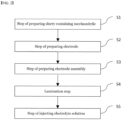
- the method for manufacturing a secondary battery with improved resistance includes: a step of preparing an electrode slurry containing a solvent and an electrode mixture containing succinonitrile (S 1); a step of preparing an electrode by coating the electrode slurry to a current collector and drying the electrode slurry (S2); a step of preparing an electrode assembly by alternately laminating the electrode and a separator (S3); a lamination step of heating and pressing the electrode assembly (S4); and a step of accommodating the laminated electrode assembly in a battery case and injecting an electrolyte solution (S5).
- a content of the succinonitrile is 5 to 40% by weight based on a total weight of the electrode mixture.
- the step (S 1) of preparing the electrode slurry includes a step of uniformly dispersing the succinonitrile in the electrode slurry.
- the step (S2) of preparing the electrode includes: a step of applying the electrode slurry on one or opposite surfaces of the current collector; and a step of drying the electrode to which the electrode slurry has been applied.
- a distribution of the succinonitrile is rearranged so that a content of the succinonitrile of an electrode surface layer far from the current collector becomes greater than a content of the succinonitrile of an electrode inner layer close to the current collector.
- the succinonitrile is positioned on an upper portion or surface of the electrode.
- the upper portion means the end region of the electrode located in a direction far from the current collector, and the surface means one surface contacting the separator, not the current collector.
- the step (S2) of preparing the electrode includes: a step of solidifying liquid succinonitrile by cooling the electrode, to which the electrode slurry has been applied, to a room temperature.
- the lamination step of heating and pressing the electrode assembly (S4) includes: a step of heating the electrode assembly to a temperature of a melting point or more of the succinonitrile.
- a heating temperature of the electrode assembly is 57°C or more, and the electrode assembly is pressed at a pressure of 30kgf/cm or less.
- the succinonitrile acts as a binder between the electrode and the separator.
- the succinonitrile in the electrode is eluted to the electrolyte solution.
- the method for manufacturing a secondary battery according to the present invention does not require a high-pressure process as in the prior art during the lamination process, damage to the separator and electrode can be minimized and process cost can be reduced.
- succinonitrile located on the surface of the electrode serves as an adhesive between the electrode and the separator, adhesive force between the electrode and the separator may be improved.
- the succinonitrile in the electrode is dissolved in the electrolyte solution, there is no resistor on the electrode and the interface between the electrode and the separator. As such, the resistance of the battery may be reduced, which is an advantage.
- FIG. 1 is a schematic diagram showing a conventional secondary battery manufacturing method.
- a binder coating layer 20 is provided on opposite surfaces of the separator 100 in the battery.
- the first electrode 200 and the second electrode 300 were alternately disposed on each side of the binder coating layer 20 to thereby manufacture an electrode assembly.
- a lamination process was performed on opposite sides of the stacked electrode assembly under conditions of high temperature/high pressure as shown in FIG. 1(a) .
- FIG. 1(b) the electrode assembly was accommodated in a battery case, and an electrolyte solution was injected to manufacture a secondary battery 1.
- the binder coating layer 20 was used to increase the adhesive force between the separator 100 and electrodes 200 and 300, but in the manufacture of the secondary battery 1, since the binder coating layer 20 still remains as an element, there is a problem of deteriorating the performance of the battery by binder coating layer 20 acting as an internal resistance.
- styrene-butadiene rubber SBR
- carboxymethyl cellulose CMC
- PVDF polyvinylidene fluoride
- the resistance continually increased due to a high pressure lamination process for improvement of adhesive force between the negative electrode and the separator.
- the present invention relates to a method of manufacturing a secondary battery having improved resistance in order to solve the above problems.
- a method for manufacturing a secondary battery according to the present invention includes:
- succinonitrile is a material mainly used as an electrolyte additive for lithium secondary batteries. Succinonitrile does not interfere with the formation of the SEI (Solid Electrolyte Interface) film of the negative electrode, and does not change the cycle life and capacity of the battery.
- SEI Solid Electrolyte Interface
- succinonitrile exists in the state of a very viscous wax at room temperature, and its melting point is 57°C, so the succinonitrile is present in a liquid state under higher temperature conditions. Therefore, succinonitrile is converted into a wax form when cooled to room temperature after liquefaction, and can serve as an adhesive between the electrode and the separator.
- succinonitrile since the succinonitrile is easily dissolved in water, succinonitrile, which is solid in a room temperature, may be dissolved in water and exist in a liquid state.
- the succinonitrile may be dissolved in a non-aqueous solvent such as a carbonate solvent
- the succinonitrile which exists in the form of an adhesive, may be dissolved and dispersed in the electrolyte solution when injecting the electrolyte solution, thereby acting as an additive to the electrolyte solution.
- the step (S 1) of preparing the electrode slurry includes a step of uniformly dispersing the succinonitrile in the electrode slurry.
- the electrode slurry shows a structure in which an electrode active material, a binder, a conductive material, and succinonitrile are uniformly dispersed in a solvent.
- an aqueous solvent or NMP, a non-aqueous solvent, etc. may be used as the solvent in the electrode slurry according to the present invention.
- Succinonitrile, a binder, and a conductive material may be mixed to prepare a pre-dispersion slurry, and an electrode active material may be added to the pre-dispersion slurry, to thereby manufacture an electrode slurry according to the present invention.
- the succinonitrile may be dissolved in water, to thereby be evenly dispersed in the slurry in a liquid form.
- the manufacturing order or method of the pre-dispersion slurry is not limited to the above example.
- a step (S2) of manufacturing an electrode, in which an electrode mixture layer is formed is performed by applying the electrode slurry, in which the succinonitrile has been uniformly dispersed, which has been prepared in the step (S1) of preparing an electrode slurry, and drying the electrode.
- the step (S2) of preparing the electrode may include: a step of applying the electrode slurry on one or opposite surfaces of the current collector; and a step of drying the electrode to which the electrode slurry has been applied. After the step of applying the electrode slurry to the current collector, the step of drying the electrode may be sequentially performed, or the applying and the drying may be simultaneously performed.
- the electrode slurry coated on the current collector forms an electrode mixture layer as the solvent is removed.
- the content of the succinonitrile may be 0.1 to 5% by weight, preferably 1.5 to 2% by weight, based on the total weight of the electrode mixture.
- the total weight of the electrode mixture refers to the weight of the portion which remains after removing the solvent through drying in the electrode slurry.
- the content and arrangement of the succinonitrile evenly dispersed in the slurry may be changed before and after the drying process.
- the drying temperature is different by sections and is preferably 110°C.
- An electrode slurry layer is formed on the current collector in a state before the slurry is applied on the current collector and is dried.
- succinonitrile is dissolved in a solvent such as water in the electrode slurry layer, the succinonitrile is evenly dispersed in the entire area of the slurry layer.
- the distribution of the succinonitrile in the electrode mixture layer becomes different from the distribution in the electrode slurry.
- the density of the succinonitrile is 0.985g/cc.
- the succinonitrile moves along the evaporation direction of the solvent. Namely, the succinonitrile, which has been uniformly dispersed in the electrode slurry layer applied on the current collector, moves to an electrode slurry layer region, which is far from the current collector, through evaporation of the solvent during the drying process.
- a distribution of the succinonitrile is rearranged so that a content of the succinonitrile of an electrode surface layer far from the current collector becomes greater than a content of the succinonitrile of an electrode inner layer close to the current collector.
- the content of the succinonitrile in the electrode mixture layer may form a concentration gradient toward the electrode surface layer from the electrode inner layer near the current collector.
- the succinonitrile is located on a region far from the current collector, that is, on the upper portion or surface.
- the upper portion means the end region of the electrode located in a direction far from the current collector, and the surface means one surface contacting the separator, not the current collector.
- the description that the succinonitrile is located on the upper portion or surface of the current collector indicates that 90% or more of the succinonitrile included in the electrode mixture layer is located on the upper portion or surface of the electrode mixture layer.
- the step (S2) of preparing the electrode of the present invention may include a step of solidifying liquid succinonitrile by cooling the electrode, to which the electrode slurry has been applied, to a room temperature.
- the succinonitrile which exists inside the electrode mixture layer on the current collector after the drying process, exists in a liquid state due to the heat applied to the electrode mixture layer during the drying process.
- the liquid succinonitrile inside the electrode mixture layer is finally solidified through the process of cooling the electrode to a room temperature after the drying process.
- the succinonitrile As mentioned in the description about the succinonitrile, if the succinonitrile is cooled to a room temperature after being liquefied, it is changed to a was form so that it can serve as a binder if heat is applied during the lamination process.
- a step of preparing an electrode assembly by alternately laminating the electrode and a separator is performed.
- the electrode may be a positive electrode and/or a negative electrode.
- the step of preparing an electrode assembly may be performed in a well know method, and in the present invention, it is preferable to prepare a stack-folding type or stack type electrode assembly.
- the succinonitrile serves as a binder between the electrode and the separator.
- a lamination step (S4) of heating and pressing the manufactured electrode assembly is performed.
- the electrode assembly is heat and pressed at a temperature of a melting point of the succinonitrile or more, specifically 57°C or more, preferably 60°C to 70°C, and the pressure range is 30kgf/cm or less.
- the electrode assembly is heated and pressed at a temperature of 57°C or more, preferably at 60°C to 70°C.
- the succinonitrile which has been in a solid state after the step (S2) of preparing an electrode, is liquefied.
- succinonitrile is evenly dispersed at the interface between the electrode and the separator according to the pressure applied to the electrode assembly at the lamination step.
- the succinonitrile in the electrode acts as a binder between the electrode and the separator.
- the succinonitrile is evenly dispersed at the interface between the electrode and the separator due to the heat and pressure at the lamination step. Liquid succinonitrile may improve the adhesive force between the electrode and the separator due to its sticky characteristic.
- the succinonitrile in a room temperature is solidified in a wax form and serves as a binder for bonding the electrode and the separator.
- the lamination step is performed by pressing the electrode assembly at a pressure of 30 kgf/cm or less, preferably 1 to 10 kgf/cm, and more preferably 1 to 5 kgf/cm.
- a strong pressure is not necessary as the electrode and the separator are bonded using the succinonitrile located on the upper portion or surface of the electrode mixture layer. This not only reduces the process cost, but also prevents physical damage to the separator due to high pressure.
- the electrode assembly to be transferred is passed between a pair of rollers and pressed to bond to each other.
- a heater is connected to a pair of pressing rollers to apply heat to the electrode assembly and pressurize to bond to each other.
- lamination is performed using a pressing roller, but it is also possible to apply press lamination. In this case, it is preferable to use a pressure of 1/10 to 1/5 of the pressure conditions of general press lamination.
- the succinonitrile on the surface of the electrode may improve the adhesive force between the electrode and the separator. This can solve the problem of a damage to a separator which may occur due to a high temperature and high pressure lamination process and may solve the problem of an increase of a resistance of the positive electrode of a battery. Further, this may reduce the binder content inside the binder layer which exists in the surface of the separator used for the electrode assembly. Further, since a high temperature and high pressure lamination process is not required, the effect of reduction of process costs can be expected.
- step (S5) of accommodating the laminated electrode assembly in a battery case and injecting an electrolyte solution is performed.
- step (S5) of accommodating the laminated electrode assembly in a battery case and injecting an electrolyte solution as the electrolyte solution is injected, the succinonitrile in the electrode is eluted to the electrolyte solution and is removed from the interface between the electrode and the separator. Thereafter, since the succinonitrile eluted to the electrolyte solution acts as an additive to the electrolyte solution, it is possible to prevent the succinonitrile from acting as a resistance component in the electrode mixture layer.
- FIG. 3 is a schematic diagram showing a method of manufacturing a secondary battery according to one embodiment of the present invention.
- FIG. 3 illustrates only a negative electrode and a separator in an electrode assembly and omits a positive electrode portion. Further, it is also possible to apply the manufacturing method according to the present invention for the positive electrode.
- FIG. 3(a) shows a state that a negative electrode slurry layer 220, in which succinonitrile 10 had been uniformly dispersed, has been applied on the negative electrode current collector 210.
- the solvent is evaporated, and the slurry layer becomes a negative electrode mixture layer, and at the same time, the succinonitrile 10 is arranged on the upper portion or surface of the negative electrode mixture layer.
- the separator 100 is laminated on the dried negative electrode 200, and in FIG. 3(d) , the succinonitrile acts as a binder for bonding the negative electrode and the separator through a lamination process.
- FIG. 3(b) shows a state that a negative electrode slurry layer 220, in which succinonitrile 10 had been uniformly dispersed, has been applied on the negative electrode current collector 210.
- the solvent is evaporated, and the slurry layer becomes a negative electrode mixture layer, and at the same time, the succinonitrile 10 is arranged on the upper portion or surface of the
- succinonitrile of the present invention acts as an adhesive means between the electrode and the separator, there is an advantage in that it is easy to adhere even in a lamination process of a lower temperature and pressure than the conventional one.
- succinonitrile is dissolved in the electrolyte injection process, which is the rear end of the battery manufacturing process, and does not remain within the interface anymore, the resistance of the battery can be minimized, thereby exhibiting an effect of preventing performance degradation of the battery.
- the electrode used in the present invention is an electrode for a lithium secondary battery.
- the lithium secondary battery includes, for example, an electrode assembly including a positive electrode, a negative electrode, and a separator interposed between the positive electrode and the negative electrode; a non-aqueous electrolyte impregnating the electrode assembly; and a battery case containing the electrode assembly and the non-aqueous electrolyte.
- the positive electrode has a structure in which a positive electrode mixture layer is stacked on one or opposite sides of a positive electrode current collector.
- the positive electrode active materials may each independently be a lithium-containing oxide, and may be the same or different.
- a lithium-containing transition metal oxide may be used as the lithium-containing oxide.
- the positive electrode mixture layer includes a conductive material and a binder polymer in addition to the positive electrode active material, and if necessary, may further include a positive electrode additive commonly used in the art.
- the positive electrode active material may be a lithium-containing oxide, and may be the same or different.
- a lithium-containing transition metal oxide may be used as the lithium-containing oxide.
- the lithium-containing transition metal oxide may be coated with a metal such as aluminum (Al) or a metal oxide.
- a metal such as aluminum (Al) or a metal oxide.
- one or more of sulfide, selenide, and halide may be used.
- the current collector used for the positive electrode is a metal having high conductivity, and any metal which the positive electrode active material slurry may be easily attached to and which is not reactive in the voltage range of the secondary battery can be used.
- the current collector for the positive electrode include aluminum, nickel, or a foil manufactured by a combination thereof.
- the current collector for the positive electrode is formed of metal components described above, and includes a metal plate having a through hole in the thickness direction, and an ion conductive porous reinforcing material filled in the through hole of the metal plate.
- the negative electrode may further include a negative electrode mixture layer, and may include a carbon material, lithium metal, silicon, or tin.
- a carbon material is used as the negative electrode active material, opposite low crystalline carbon and high crystalline carbon may be used.
- Representative examples of low crystalline carbon include soft carbon and hard carbon.
- Representative examples of high crystalline carbon include natural graphite, kish graphite, pyrolytic carbon, mesophase pitch based carbon fiber, mesocarbon microbeads, mesophase pitches, and high-temperature calcined carbons such as petroleum or coal tar pitch derived cokes.
- Non-limiting examples of the current collector used for the negative electrode include copper, gold, nickel, or a foil manufactured by a copper alloy or a combination thereof.
- the current collector may be used by stacking substrates made of the above materials.
- the current collector for the negative electrode is formed of metal components described above, and includes a metal plate having a through hole in the thickness direction, and an ion conductive porous reinforcing material filled in the through hole of the metal plate.
- the negative electrode may include a conductive material and a binder commonly used in the art.
- the separator may be made of any porous substrate used in a lithium secondary battery, and for example, a polyolefin-based porous membrane or a nonwoven fabric may be used, but the present invention is not particularly limited thereto.
- the polyolefin-based porous membrane include polyethylene such as high density polyethylene, linear low density polyethylene, low density polyethylene, ultra high molecular weight polyethylene, and a membrane in which polyolefin-based polymers, such as polypropylene, polybutylene, and polypentene, are each formed alone or in a mixture thereof.
- a non-aqueous electrolyte containing a non-aqueous electrolyte solution may be used as the electrolyte solution.
- the non-aqueous electrolyte include N-methyl-2-pyrrolidinone, propylene carbonate, ethylene carbonate, butylenecarbonate, dimethyl carbonate, diethyl carbonate, gamma-Butyrolactone, 1,2-dimethoxyethane, tetrahydroxyfuran, 2-methyltetrahydrofuran, dimethylsulfoxide, 1,3-dioxolane, formamide, dimethylformamide, dioxolane, acetonitrile, nitromethane, methyl formate, methyl acetate, phosphoric acid triester, trimethoxymethane, dioxolane derivatives, sulfolane, methyl sulfolane, 1,3-dimethyl-2-imidazolidinone, propylene carbonate derivatives, tetrahydrofuran derivative
- the present invention provides a vehicle or large-capacity energy storage device including the secondary battery described above.
- the vehicle is a hybrid or electric vehicle.
- a non-aqueous electrolyte solution as a solvent was added to a positive electrode mixture containing 2 wt% of succinonitrile (SN), 2.5 wt% of PVDF (binder), 2.5 wt% of carbon black (conductive agent), and 93 wt% of LiCoO 2 as the positive electrode active material, to thereby prepare a positive electrode slurry, which was then applied on opposite surfaces of the current collector, and dried and rolled to thereby manufacture a positive electrode.
- SN succinonitrile
- PVDF binder
- carbon black conductive agent
- a non-aqueous electrolyte solution as a solvent was added to a negative electrode mixture containing 2 wt% of succinonitrile (SN), 1.5 wt% of SBR (binder), 1.0 wt% of CMC (binder), 2.5 wt% of carbon black (conductive agent), and 93 wt% of graphite as the negative electrode active material, to thereby prepare a negative electrode slurry, which was then applied on opposite surfaces of the current collector, and dried and rolled to thereby manufacture a negative electrode.
- SN succinonitrile
- SBR synBR
- CMC binder
- conductive agent conductive agent
- a porous polyethylene containing a coating layer containing 15 wt% PVDF binder was used as the separator.
- a positive electrode was placed on one side of the separator, and a negative electrode was placed on the opposite side, and then laminated to manufacture an electrode assembly. At this time, the electrode assembly was roll-laminated at the condition of 80°C and 5 kgf/cm.
- the laminated electrode assembly was accommodated in a pouch-type battery case, and an electrolyte solution was injected to manufacture a secondary battery.
- Example 2 When SN content in the electrode mixture is set to 3% in Example 1
- Example 3 When SN content in the electrode mixture is set to 4% in Example 1
- Example 4 When SN content in the electrode mixture is set to 5% in Example 1
- Example 5 In Example 1, SN is not contained in the positive electrode mixture, and SN is contained only in the negative electrode mixture by 2%.
- Example 6 Change roll lamination pressure to 10 kgf/cm in Example 5
- Example 7 Change roll lamination pressure to 30 kgf/cm in Example 5
- Comparative example 4 in Example 5, SN is not contained in the positive electrode mixture, and SN is contained only in the negative electrode mixture by 0.05%.
- the adhesive force was measured while detaching the separator from the negative electrode at a rate of 20mm/min at the angel of 90 degrees.
- the adhesive force was 200 gf/20 mm
- the electrode was bent.
- the adhesive force was 200 gf/ 20 mm or more
- the adhesive force between the separator and the electrode is excessively strong, so that it is not possible to detach the separator from the electrode when measuring the adhesive force, thereby showing a phenomenon that the electrode is bent. In such a case, the resistance is generally high due to excessive lamination conditions.
- the succinonitrile which existed in the slurry in the drying step of the electrode manufacturing process, is moved to the upper portion of the electrode or the electrode surface layer, so that the succinonitrile is rearranged in the electrode.
- the succinonitrile of a low density which evenly existed in the electrode slurry, are rearranged from the electrode inner layer close to the current collector to an electrode surface layer far from the current collector through the electrode drying process, the succinonitrile is finally positioned on the upper portion or surface of the electrode.
- the succinonitrile which is positioned on the surface of the electrode, is liquefied by the lamination condition, thereby acting as a binder for bonding the separator and the electrode. Thereafter, in the condition after the lamination process, the succinonitrile is solidified and improves the adhesive force between the separator and the electrode. According to Table 1, in the example of the present invention, as an appropriate amount of succinonitrile is used, the adhesive force between the electrode and the separator is improved.
- Examples 1 to 4 are different from Comparative examples 1 and 2 only in the SN content in the electrode of the same condition.
- the adhesive force of the negative electrode/separator of Examples 1 to 4 is superior to that of Comparative example 1 or 2, and the cyclic characteristics of Examples 1 to 4 are also superior to those of Comparative example 1 or 2.
- Comparative example 1 if too small amount of SN is applied to the positive electrode and the negative electrode, the adhesive force is not sufficiently secured, and the capacity was low compared to 2.0C discharge. In Comparative example 2, if too much succinonitrile is applied, the adhesive force is good, but the capacity also low, compared to 2.0C discharge. Since the viscosity of the succinonitrile is high, when too much succinonitrile is applied, the ion conductivity becomes low, thereby increasing the resistance.
- Example 5 and Comparative example 4 are the same except for the SN content in the negative electrode mixture.
- the adhesive force between the negative electrode and the separator becomes too low.
- 2.0C discharge capacity of Comparative example 4 was lower than that of Example 4.
- Comparative example 1 since the succinonitrile content was low, the adhesive force between the electrode and the separator was not improved.
- Comparative example 2 since the succinonitrile content was high, the succinonitrile, which remained on the surface of the electrode and the separator, acted as a resistance, thereby deteriorating cycle characteristics. Since the lamination pressure of Comparative example 3 is greater than that of Examples 5 to 7, the binder between the positive electrode and the separator melts and acts as a resistance, and as a damage to the separator occurs, the electrode is bent and at the same time, cycle characteristics are deteriorated. Since the SN content of Comparative example 4 is smaller than that of Example 5, sufficient adhesive force between the electrode and the separator was not secured, and the cycle characteristics were not improved.
Landscapes
- Chemical & Material Sciences (AREA)
- General Chemical & Material Sciences (AREA)
- Chemical Kinetics & Catalysis (AREA)
- Electrochemistry (AREA)
- Engineering & Computer Science (AREA)
- Manufacturing & Machinery (AREA)
- Inorganic Chemistry (AREA)
- Materials Engineering (AREA)
- General Physics & Mathematics (AREA)
- Condensed Matter Physics & Semiconductors (AREA)
- Physics & Mathematics (AREA)
- Secondary Cells (AREA)
- Battery Electrode And Active Subsutance (AREA)
Applications Claiming Priority (2)
| Application Number | Priority Date | Filing Date | Title |
|---|---|---|---|
| KR1020200054039A KR102839736B1 (ko) | 2020-05-06 | 2020-05-06 | 저항이 개선된 이차전지 제조방법 |
| PCT/KR2020/019051 WO2021225248A1 (ko) | 2020-05-06 | 2020-12-24 | 저항이 개선된 이차전지 제조방법 |
Publications (3)
| Publication Number | Publication Date |
|---|---|
| EP3985778A1 EP3985778A1 (en) | 2022-04-20 |
| EP3985778A4 EP3985778A4 (en) | 2022-09-14 |
| EP3985778B1 true EP3985778B1 (en) | 2024-02-14 |
Family
ID=78468043
Family Applications (1)
| Application Number | Title | Priority Date | Filing Date |
|---|---|---|---|
| EP20934605.5A Active EP3985778B1 (en) | 2020-05-06 | 2020-12-24 | Method for manufacturing secondary battery having improved resistance |
Country Status (9)
| Country | Link |
|---|---|
| US (1) | US20220263087A1 (pl) |
| EP (1) | EP3985778B1 (pl) |
| JP (1) | JP7313534B2 (pl) |
| KR (1) | KR102839736B1 (pl) |
| CN (1) | CN114127980B (pl) |
| ES (1) | ES2974413T3 (pl) |
| HU (1) | HUE065632T2 (pl) |
| PL (1) | PL3985778T3 (pl) |
| WO (1) | WO2021225248A1 (pl) |
Families Citing this family (1)
| Publication number | Priority date | Publication date | Assignee | Title |
|---|---|---|---|---|
| US12244037B2 (en) | 2021-07-09 | 2025-03-04 | Lg Energy Solution, Ltd. | Manufacturing method for electrode assembly |
Family Cites Families (22)
| Publication number | Priority date | Publication date | Assignee | Title |
|---|---|---|---|---|
| CA2553667C (en) * | 2004-02-16 | 2013-06-11 | Lg Chem, Ltd. | Electrode for lithium secondary battery |
| KR100588288B1 (ko) | 2004-02-16 | 2006-06-09 | 주식회사 엘지화학 | 리튬 이차 전지용 전극 |
| JP4954468B2 (ja) | 2004-12-10 | 2012-06-13 | 日立マクセルエナジー株式会社 | 捲回電極およびその製造方法、並びに電池の製造方法 |
| KR20140113186A (ko) * | 2013-03-15 | 2014-09-24 | 삼성에스디아이 주식회사 | 전극 조립체 및 이를 이용한 이차전지의 제조방법 |
| KR20140123007A (ko) * | 2013-04-11 | 2014-10-21 | 주식회사 엘지화학 | 라운드 코너를 포함하는 전지셀 |
| WO2015045400A1 (ja) * | 2013-09-30 | 2015-04-02 | 三洋電機株式会社 | 偏平形非水電解質二次電池及びそれを用いた組電池 |
| JP2016009572A (ja) * | 2014-06-24 | 2016-01-18 | 三洋化成工業株式会社 | 電気化学デバイス用電極の製造方法 |
| FR3040550B1 (fr) | 2015-08-25 | 2017-08-11 | Commissariat Energie Atomique | Batterie au lithium-ion gelifiee |
| WO2017197406A1 (en) * | 2016-05-13 | 2017-11-16 | Quantumscape Corporation | Solid electrolyte separator bonding agent |
| EP3522263B1 (en) * | 2016-09-29 | 2020-08-26 | Envision AESC Japan Ltd. | Secondary cell |
| KR102518992B1 (ko) * | 2017-02-03 | 2023-04-07 | 주식회사 엘지에너지솔루션 | 고온 저장 특성이 향상된 리튬 이차전지의 제조 방법 |
| US10985373B2 (en) * | 2017-02-27 | 2021-04-20 | Global Graphene Group, Inc. | Lithium battery cathode and method of manufacturing |
| JP6986077B2 (ja) * | 2017-07-04 | 2021-12-22 | マクセル株式会社 | リチウムイオン二次電池およびその製造方法 |
| KR102449854B1 (ko) * | 2018-01-18 | 2022-09-29 | 주식회사 엘지에너지솔루션 | 고체 전해질 전지용 음극 활물질 슬러리 및 그로부터 제조된 고체 전해질 전지용 음극 |
| KR102415543B1 (ko) * | 2018-01-18 | 2022-06-30 | 주식회사 엘지에너지솔루션 | 고체 전해질 전지용 전극 및 그를 포함하는 고체 전해질 전지 |
| KR102338937B1 (ko) | 2018-04-26 | 2021-12-10 | 주식회사 엘지에너지솔루션 | 고체 전해질 전지 및 그를 포함하는 전지모듈 |
| KR102281373B1 (ko) * | 2018-04-26 | 2021-07-22 | 주식회사 엘지에너지솔루션 | 고체 전해질 전지용 양극 및 그를 포함하는 고체 전해질 전지 |
| JP2019189822A (ja) * | 2018-04-27 | 2019-10-31 | 日立化成株式会社 | 共融混合体、ポリマ、電気化学デバイス用電極及びその製造方法、電気化学デバイス、共融混合体電解質組成物、並びにポリマ電解質組成物 |
| KR102028611B1 (ko) * | 2018-07-27 | 2019-10-04 | 장명희 | 이차전지 제조용 라미네이션 장치 |
| KR102637832B1 (ko) | 2018-11-09 | 2024-02-19 | 주식회사 케이씨텍 | 연마 장치용 캐리어 헤드 및 이에 사용되는 멤브레인 |
| CN110504491B (zh) * | 2019-08-28 | 2020-10-02 | 中南大学 | 改性丁二腈修饰全固态锂电池的方法 |
| KR102773618B1 (ko) * | 2019-12-09 | 2025-02-27 | 주식회사 엘지에너지솔루션 | 저항이 개선된 이차전지 제조방법 |
-
2020
- 2020-05-06 KR KR1020200054039A patent/KR102839736B1/ko active Active
- 2020-12-24 ES ES20934605T patent/ES2974413T3/es active Active
- 2020-12-24 WO PCT/KR2020/019051 patent/WO2021225248A1/ko not_active Ceased
- 2020-12-24 PL PL20934605.5T patent/PL3985778T3/pl unknown
- 2020-12-24 HU HUE20934605A patent/HUE065632T2/hu unknown
- 2020-12-24 US US17/627,495 patent/US20220263087A1/en active Pending
- 2020-12-24 EP EP20934605.5A patent/EP3985778B1/en active Active
- 2020-12-24 JP JP2022501320A patent/JP7313534B2/ja active Active
- 2020-12-24 CN CN202080048316.1A patent/CN114127980B/zh active Active
Also Published As
| Publication number | Publication date |
|---|---|
| JP2022540233A (ja) | 2022-09-14 |
| KR102839736B1 (ko) | 2025-07-28 |
| CN114127980B (zh) | 2023-11-24 |
| US20220263087A1 (en) | 2022-08-18 |
| EP3985778A1 (en) | 2022-04-20 |
| EP3985778A4 (en) | 2022-09-14 |
| JP7313534B2 (ja) | 2023-07-24 |
| CN114127980A (zh) | 2022-03-01 |
| ES2974413T3 (es) | 2024-06-27 |
| HUE065632T2 (hu) | 2024-06-28 |
| KR20210135861A (ko) | 2021-11-16 |
| PL3985778T3 (pl) | 2024-05-06 |
| WO2021225248A1 (ko) | 2021-11-11 |
Similar Documents
| Publication | Publication Date | Title |
|---|---|---|
| KR102790285B1 (ko) | 음극의 전리튬화 방법 및 이로부터 제조된 음극 | |
| KR101202863B1 (ko) | 배터리용 음극 및 이를 사용한 리튬 이온 배터리 | |
| EP2238643B1 (en) | Pouch-type lithium secondary battery | |
| US7503942B2 (en) | Method of making electrochemical device | |
| KR101862433B1 (ko) | 리튬 이온 캐패시터 | |
| US9893357B2 (en) | Cathode mix and nonaqueous electrolyte battery | |
| US20100119940A1 (en) | Secondary battery | |
| KR102460008B1 (ko) | 음극의 전리튬화 방법 및 이로부터 수득되는 음극 | |
| KR20080020961A (ko) | 부극 및 그것을 이용한 비수전해질 이차 전지 | |
| KR20200096130A (ko) | 절연필름을 포함하는 전극 조립체, 이의 제조방법, 및 이를 포함하는 리튬 이차전지 | |
| JP7589517B2 (ja) | 蓄電装置用正極の製造方法 | |
| KR102838736B1 (ko) | 이차전지용 양극, 그 제조방법 및 이를 포함하는 리튬 이차전지 | |
| KR102754585B1 (ko) | 리튬 이차전지 및 그 제조방법 | |
| JP6057644B2 (ja) | リチウムイオン電池 | |
| KR20210120686A (ko) | 음극의 제조방법 | |
| KR102846053B1 (ko) | 리튬 이차전지용 음극 및 이를 구비한 리튬 이차전지 | |
| US12119480B2 (en) | Method for manufacturing secondary battery with improved resistance | |
| EP3985778B1 (en) | Method for manufacturing secondary battery having improved resistance | |
| US12249720B2 (en) | Electrode assembly having enhanced safety and lithium secondary battery comprising same | |
| US20200373619A1 (en) | Electrolytic solution for lithium-ion secondary battery and lithium-ion secondary battery | |
| CN1790571B (zh) | 一种高电压非对称超级电容器及其负极的制备方法 | |
| JP5846031B2 (ja) | リチウムイオン二次電池及び非水電解液 | |
| KR102911409B1 (ko) | 리튬 이차 전지용 전극, 이의 제조 방법 및 이를 포함하는 리튬 이차 전지 | |
| KR102782616B1 (ko) | 전극 조립체 및 이를 포함하는 이차 전지 | |
| US20260058119A1 (en) | Method for manufacturing secondary battery |
Legal Events
| Date | Code | Title | Description |
|---|---|---|---|
| STAA | Information on the status of an ep patent application or granted ep patent |
Free format text: STATUS: THE INTERNATIONAL PUBLICATION HAS BEEN MADE |
|
| PUAI | Public reference made under article 153(3) epc to a published international application that has entered the european phase |
Free format text: ORIGINAL CODE: 0009012 |
|
| STAA | Information on the status of an ep patent application or granted ep patent |
Free format text: STATUS: REQUEST FOR EXAMINATION WAS MADE |
|
| 17P | Request for examination filed |
Effective date: 20220111 |
|
| AK | Designated contracting states |
Kind code of ref document: A1 Designated state(s): AL AT BE BG CH CY CZ DE DK EE ES FI FR GB GR HR HU IE IS IT LI LT LU LV MC MK MT NL NO PL PT RO RS SE SI SK SM TR |
|
| A4 | Supplementary search report drawn up and despatched |
Effective date: 20220812 |
|
| RIC1 | Information provided on ipc code assigned before grant |
Ipc: H01M 10/052 20100101ALI20220808BHEP Ipc: H01M 10/04 20060101ALI20220808BHEP Ipc: H01M 4/04 20060101ALI20220808BHEP Ipc: H01M 4/139 20100101ALI20220808BHEP Ipc: H01M 50/46 20210101ALI20220808BHEP Ipc: H01M 4/62 20060101ALI20220808BHEP Ipc: H01M 10/0583 20100101ALI20220808BHEP Ipc: H01M 10/0585 20100101AFI20220808BHEP |
|
| DAV | Request for validation of the european patent (deleted) | ||
| DAX | Request for extension of the european patent (deleted) | ||
| GRAP | Despatch of communication of intention to grant a patent |
Free format text: ORIGINAL CODE: EPIDOSNIGR1 |
|
| STAA | Information on the status of an ep patent application or granted ep patent |
Free format text: STATUS: GRANT OF PATENT IS INTENDED |
|
| RIC1 | Information provided on ipc code assigned before grant |
Ipc: H01M 10/052 20100101ALI20231010BHEP Ipc: H01M 10/04 20060101ALI20231010BHEP Ipc: H01M 4/04 20060101ALI20231010BHEP Ipc: H01M 4/139 20100101ALI20231010BHEP Ipc: H01M 50/46 20210101ALI20231010BHEP Ipc: H01M 4/62 20060101ALI20231010BHEP Ipc: H01M 10/0583 20100101ALI20231010BHEP Ipc: H01M 10/0585 20100101AFI20231010BHEP |
|
| INTG | Intention to grant announced |
Effective date: 20231024 |
|
| P01 | Opt-out of the competence of the unified patent court (upc) registered |
Effective date: 20231030 |
|
| GRAS | Grant fee paid |
Free format text: ORIGINAL CODE: EPIDOSNIGR3 |
|
| GRAA | (expected) grant |
Free format text: ORIGINAL CODE: 0009210 |
|
| STAA | Information on the status of an ep patent application or granted ep patent |
Free format text: STATUS: THE PATENT HAS BEEN GRANTED |
|
| AK | Designated contracting states |
Kind code of ref document: B1 Designated state(s): AL AT BE BG CH CY CZ DE DK EE ES FI FR GB GR HR HU IE IS IT LI LT LU LV MC MK MT NL NO PL PT RO RS SE SI SK SM TR |
|
| REG | Reference to a national code |
Ref country code: GB Ref legal event code: FG4D |
|
| REG | Reference to a national code |
Ref country code: CH Ref legal event code: EP |
|
| REG | Reference to a national code |
Ref country code: DE Ref legal event code: R096 Ref document number: 602020025880 Country of ref document: DE |
|
| REG | Reference to a national code |
Ref country code: IE Ref legal event code: FG4D |
|
| REG | Reference to a national code |
Ref country code: SE Ref legal event code: TRGR |
|
| REG | Reference to a national code |
Ref country code: LT Ref legal event code: MG9D |
|
| REG | Reference to a national code |
Ref country code: NL Ref legal event code: MP Effective date: 20240214 |
|
| REG | Reference to a national code |
Ref country code: ES Ref legal event code: FG2A Ref document number: 2974413 Country of ref document: ES Kind code of ref document: T3 Effective date: 20240627 |
|
| REG | Reference to a national code |
Ref country code: HU Ref legal event code: AG4A Ref document number: E065632 Country of ref document: HU |
|
| PG25 | Lapsed in a contracting state [announced via postgrant information from national office to epo] |
Ref country code: IS Free format text: LAPSE BECAUSE OF FAILURE TO SUBMIT A TRANSLATION OF THE DESCRIPTION OR TO PAY THE FEE WITHIN THE PRESCRIBED TIME-LIMIT Effective date: 20240614 |
|
| PG25 | Lapsed in a contracting state [announced via postgrant information from national office to epo] |
Ref country code: LT Free format text: LAPSE BECAUSE OF FAILURE TO SUBMIT A TRANSLATION OF THE DESCRIPTION OR TO PAY THE FEE WITHIN THE PRESCRIBED TIME-LIMIT Effective date: 20240214 |
|
| PG25 | Lapsed in a contracting state [announced via postgrant information from national office to epo] |
Ref country code: GR Free format text: LAPSE BECAUSE OF FAILURE TO SUBMIT A TRANSLATION OF THE DESCRIPTION OR TO PAY THE FEE WITHIN THE PRESCRIBED TIME-LIMIT Effective date: 20240515 |
|
| REG | Reference to a national code |
Ref country code: AT Ref legal event code: MK05 Ref document number: 1657838 Country of ref document: AT Kind code of ref document: T Effective date: 20240214 |
|
| PG25 | Lapsed in a contracting state [announced via postgrant information from national office to epo] |
Ref country code: RS Free format text: LAPSE BECAUSE OF FAILURE TO SUBMIT A TRANSLATION OF THE DESCRIPTION OR TO PAY THE FEE WITHIN THE PRESCRIBED TIME-LIMIT Effective date: 20240514 Ref country code: HR Free format text: LAPSE BECAUSE OF FAILURE TO SUBMIT A TRANSLATION OF THE DESCRIPTION OR TO PAY THE FEE WITHIN THE PRESCRIBED TIME-LIMIT Effective date: 20240214 Ref country code: NL Free format text: LAPSE BECAUSE OF FAILURE TO SUBMIT A TRANSLATION OF THE DESCRIPTION OR TO PAY THE FEE WITHIN THE PRESCRIBED TIME-LIMIT Effective date: 20240214 |
|
| PG25 | Lapsed in a contracting state [announced via postgrant information from national office to epo] |
Ref country code: AT Free format text: LAPSE BECAUSE OF FAILURE TO SUBMIT A TRANSLATION OF THE DESCRIPTION OR TO PAY THE FEE WITHIN THE PRESCRIBED TIME-LIMIT Effective date: 20240214 |
|
| PG25 | Lapsed in a contracting state [announced via postgrant information from national office to epo] |
Ref country code: RS Free format text: LAPSE BECAUSE OF FAILURE TO SUBMIT A TRANSLATION OF THE DESCRIPTION OR TO PAY THE FEE WITHIN THE PRESCRIBED TIME-LIMIT Effective date: 20240514 Ref country code: NO Free format text: LAPSE BECAUSE OF FAILURE TO SUBMIT A TRANSLATION OF THE DESCRIPTION OR TO PAY THE FEE WITHIN THE PRESCRIBED TIME-LIMIT Effective date: 20240514 Ref country code: NL Free format text: LAPSE BECAUSE OF FAILURE TO SUBMIT A TRANSLATION OF THE DESCRIPTION OR TO PAY THE FEE WITHIN THE PRESCRIBED TIME-LIMIT Effective date: 20240214 Ref country code: LT Free format text: LAPSE BECAUSE OF FAILURE TO SUBMIT A TRANSLATION OF THE DESCRIPTION OR TO PAY THE FEE WITHIN THE PRESCRIBED TIME-LIMIT Effective date: 20240214 Ref country code: IS Free format text: LAPSE BECAUSE OF FAILURE TO SUBMIT A TRANSLATION OF THE DESCRIPTION OR TO PAY THE FEE WITHIN THE PRESCRIBED TIME-LIMIT Effective date: 20240614 Ref country code: HR Free format text: LAPSE BECAUSE OF FAILURE TO SUBMIT A TRANSLATION OF THE DESCRIPTION OR TO PAY THE FEE WITHIN THE PRESCRIBED TIME-LIMIT Effective date: 20240214 Ref country code: GR Free format text: LAPSE BECAUSE OF FAILURE TO SUBMIT A TRANSLATION OF THE DESCRIPTION OR TO PAY THE FEE WITHIN THE PRESCRIBED TIME-LIMIT Effective date: 20240515 Ref country code: FI Free format text: LAPSE BECAUSE OF FAILURE TO SUBMIT A TRANSLATION OF THE DESCRIPTION OR TO PAY THE FEE WITHIN THE PRESCRIBED TIME-LIMIT Effective date: 20240214 Ref country code: BG Free format text: LAPSE BECAUSE OF FAILURE TO SUBMIT A TRANSLATION OF THE DESCRIPTION OR TO PAY THE FEE WITHIN THE PRESCRIBED TIME-LIMIT Effective date: 20240214 Ref country code: AT Free format text: LAPSE BECAUSE OF FAILURE TO SUBMIT A TRANSLATION OF THE DESCRIPTION OR TO PAY THE FEE WITHIN THE PRESCRIBED TIME-LIMIT Effective date: 20240214 |
|
| PG25 | Lapsed in a contracting state [announced via postgrant information from national office to epo] |
Ref country code: PT Free format text: LAPSE BECAUSE OF FAILURE TO SUBMIT A TRANSLATION OF THE DESCRIPTION OR TO PAY THE FEE WITHIN THE PRESCRIBED TIME-LIMIT Effective date: 20240614 |
|
| PG25 | Lapsed in a contracting state [announced via postgrant information from national office to epo] |
Ref country code: PT Free format text: LAPSE BECAUSE OF FAILURE TO SUBMIT A TRANSLATION OF THE DESCRIPTION OR TO PAY THE FEE WITHIN THE PRESCRIBED TIME-LIMIT Effective date: 20240614 Ref country code: LV Free format text: LAPSE BECAUSE OF FAILURE TO SUBMIT A TRANSLATION OF THE DESCRIPTION OR TO PAY THE FEE WITHIN THE PRESCRIBED TIME-LIMIT Effective date: 20240214 |
|
| PG25 | Lapsed in a contracting state [announced via postgrant information from national office to epo] |
Ref country code: DK Free format text: LAPSE BECAUSE OF FAILURE TO SUBMIT A TRANSLATION OF THE DESCRIPTION OR TO PAY THE FEE WITHIN THE PRESCRIBED TIME-LIMIT Effective date: 20240214 |
|
| PG25 | Lapsed in a contracting state [announced via postgrant information from national office to epo] |
Ref country code: SM Free format text: LAPSE BECAUSE OF FAILURE TO SUBMIT A TRANSLATION OF THE DESCRIPTION OR TO PAY THE FEE WITHIN THE PRESCRIBED TIME-LIMIT Effective date: 20240214 |
|
| PG25 | Lapsed in a contracting state [announced via postgrant information from national office to epo] |
Ref country code: CZ Free format text: LAPSE BECAUSE OF FAILURE TO SUBMIT A TRANSLATION OF THE DESCRIPTION OR TO PAY THE FEE WITHIN THE PRESCRIBED TIME-LIMIT Effective date: 20240214 Ref country code: EE Free format text: LAPSE BECAUSE OF FAILURE TO SUBMIT A TRANSLATION OF THE DESCRIPTION OR TO PAY THE FEE WITHIN THE PRESCRIBED TIME-LIMIT Effective date: 20240214 |
|
| PG25 | Lapsed in a contracting state [announced via postgrant information from national office to epo] |
Ref country code: SK Free format text: LAPSE BECAUSE OF FAILURE TO SUBMIT A TRANSLATION OF THE DESCRIPTION OR TO PAY THE FEE WITHIN THE PRESCRIBED TIME-LIMIT Effective date: 20240214 |
|
| PG25 | Lapsed in a contracting state [announced via postgrant information from national office to epo] |
Ref country code: SM Free format text: LAPSE BECAUSE OF FAILURE TO SUBMIT A TRANSLATION OF THE DESCRIPTION OR TO PAY THE FEE WITHIN THE PRESCRIBED TIME-LIMIT Effective date: 20240214 Ref country code: SK Free format text: LAPSE BECAUSE OF FAILURE TO SUBMIT A TRANSLATION OF THE DESCRIPTION OR TO PAY THE FEE WITHIN THE PRESCRIBED TIME-LIMIT Effective date: 20240214 Ref country code: RO Free format text: LAPSE BECAUSE OF FAILURE TO SUBMIT A TRANSLATION OF THE DESCRIPTION OR TO PAY THE FEE WITHIN THE PRESCRIBED TIME-LIMIT Effective date: 20240214 Ref country code: EE Free format text: LAPSE BECAUSE OF FAILURE TO SUBMIT A TRANSLATION OF THE DESCRIPTION OR TO PAY THE FEE WITHIN THE PRESCRIBED TIME-LIMIT Effective date: 20240214 Ref country code: DK Free format text: LAPSE BECAUSE OF FAILURE TO SUBMIT A TRANSLATION OF THE DESCRIPTION OR TO PAY THE FEE WITHIN THE PRESCRIBED TIME-LIMIT Effective date: 20240214 Ref country code: CZ Free format text: LAPSE BECAUSE OF FAILURE TO SUBMIT A TRANSLATION OF THE DESCRIPTION OR TO PAY THE FEE WITHIN THE PRESCRIBED TIME-LIMIT Effective date: 20240214 |
|
| REG | Reference to a national code |
Ref country code: DE Ref legal event code: R097 Ref document number: 602020025880 Country of ref document: DE |
|
| PG25 | Lapsed in a contracting state [announced via postgrant information from national office to epo] |
Ref country code: IT Free format text: LAPSE BECAUSE OF FAILURE TO SUBMIT A TRANSLATION OF THE DESCRIPTION OR TO PAY THE FEE WITHIN THE PRESCRIBED TIME-LIMIT Effective date: 20240214 |
|
| PLBE | No opposition filed within time limit |
Free format text: ORIGINAL CODE: 0009261 |
|
| STAA | Information on the status of an ep patent application or granted ep patent |
Free format text: STATUS: NO OPPOSITION FILED WITHIN TIME LIMIT |
|
| PG25 | Lapsed in a contracting state [announced via postgrant information from national office to epo] |
Ref country code: IT Free format text: LAPSE BECAUSE OF FAILURE TO SUBMIT A TRANSLATION OF THE DESCRIPTION OR TO PAY THE FEE WITHIN THE PRESCRIBED TIME-LIMIT Effective date: 20240214 |
|
| 26N | No opposition filed |
Effective date: 20241115 |
|
| PG25 | Lapsed in a contracting state [announced via postgrant information from national office to epo] |
Ref country code: SI Free format text: LAPSE BECAUSE OF FAILURE TO SUBMIT A TRANSLATION OF THE DESCRIPTION OR TO PAY THE FEE WITHIN THE PRESCRIBED TIME-LIMIT Effective date: 20240214 |
|
| PG25 | Lapsed in a contracting state [announced via postgrant information from national office to epo] |
Ref country code: MC Free format text: LAPSE BECAUSE OF FAILURE TO SUBMIT A TRANSLATION OF THE DESCRIPTION OR TO PAY THE FEE WITHIN THE PRESCRIBED TIME-LIMIT Effective date: 20240214 |
|
| REG | Reference to a national code |
Ref country code: CH Ref legal event code: PL |
|
| PG25 | Lapsed in a contracting state [announced via postgrant information from national office to epo] |
Ref country code: LU Free format text: LAPSE BECAUSE OF NON-PAYMENT OF DUE FEES Effective date: 20241224 |
|
| PG25 | Lapsed in a contracting state [announced via postgrant information from national office to epo] |
Ref country code: CH Free format text: LAPSE BECAUSE OF NON-PAYMENT OF DUE FEES Effective date: 20241231 |
|
| PG25 | Lapsed in a contracting state [announced via postgrant information from national office to epo] |
Ref country code: IE Free format text: LAPSE BECAUSE OF NON-PAYMENT OF DUE FEES Effective date: 20241224 |
|
| PGFP | Annual fee paid to national office [announced via postgrant information from national office to epo] |
Ref country code: DE Payment date: 20251120 Year of fee payment: 6 |
|
| PGFP | Annual fee paid to national office [announced via postgrant information from national office to epo] |
Ref country code: GB Payment date: 20251120 Year of fee payment: 6 |
|
| PGFP | Annual fee paid to national office [announced via postgrant information from national office to epo] |
Ref country code: HU Payment date: 20251216 Year of fee payment: 6 Ref country code: FR Payment date: 20251125 Year of fee payment: 6 |
|
| PGFP | Annual fee paid to national office [announced via postgrant information from national office to epo] |
Ref country code: BE Payment date: 20251120 Year of fee payment: 6 |
|
| PGFP | Annual fee paid to national office [announced via postgrant information from national office to epo] |
Ref country code: SE Payment date: 20251121 Year of fee payment: 6 |
|
| PGFP | Annual fee paid to national office [announced via postgrant information from national office to epo] |
Ref country code: PL Payment date: 20251125 Year of fee payment: 6 |
|
| PGFP | Annual fee paid to national office [announced via postgrant information from national office to epo] |
Ref country code: ES Payment date: 20260122 Year of fee payment: 6 |