EP3985908B1 - Downlink-übertragungsverfahren und endgerät - Google Patents
Downlink-übertragungsverfahren und endgerät Download PDFInfo
- Publication number
- EP3985908B1 EP3985908B1 EP20919297.0A EP20919297A EP3985908B1 EP 3985908 B1 EP3985908 B1 EP 3985908B1 EP 20919297 A EP20919297 A EP 20919297A EP 3985908 B1 EP3985908 B1 EP 3985908B1
- Authority
- EP
- European Patent Office
- Prior art keywords
- ssb
- downlink signal
- terminal device
- multiplexing mode
- pcid
- Prior art date
- Legal status (The legal status is an assumption and is not a legal conclusion. Google has not performed a legal analysis and makes no representation as to the accuracy of the status listed.)
- Active
Links
Images


Classifications
-
- H—ELECTRICITY
- H04—ELECTRIC COMMUNICATION TECHNIQUE
- H04L—TRANSMISSION OF DIGITAL INFORMATION, e.g. TELEGRAPHIC COMMUNICATION
- H04L5/00—Arrangements affording multiple use of the transmission path
- H04L5/0001—Arrangements for dividing the transmission path
- H04L5/0003—Two-dimensional division
- H04L5/0005—Time-frequency
- H04L5/0007—Time-frequency the frequencies being orthogonal, e.g. OFDM(A) or DMT
-
- H—ELECTRICITY
- H04—ELECTRIC COMMUNICATION TECHNIQUE
- H04L—TRANSMISSION OF DIGITAL INFORMATION, e.g. TELEGRAPHIC COMMUNICATION
- H04L5/00—Arrangements affording multiple use of the transmission path
- H04L5/003—Arrangements for allocating sub-channels of the transmission path
- H04L5/0048—Allocation of pilot signals, i.e. of signals known to the receiver
-
- H—ELECTRICITY
- H04—ELECTRIC COMMUNICATION TECHNIQUE
- H04W—WIRELESS COMMUNICATION NETWORKS
- H04W72/00—Local resource management
- H04W72/20—Control channels or signalling for resource management
- H04W72/23—Control channels or signalling for resource management in the downlink direction of a wireless link, i.e. towards a terminal
-
- H—ELECTRICITY
- H04—ELECTRIC COMMUNICATION TECHNIQUE
- H04L—TRANSMISSION OF DIGITAL INFORMATION, e.g. TELEGRAPHIC COMMUNICATION
- H04L1/00—Arrangements for detecting or preventing errors in the information received
- H04L1/08—Arrangements for detecting or preventing errors in the information received by repeating transmission, e.g. Verdan system
-
- H—ELECTRICITY
- H04—ELECTRIC COMMUNICATION TECHNIQUE
- H04L—TRANSMISSION OF DIGITAL INFORMATION, e.g. TELEGRAPHIC COMMUNICATION
- H04L27/00—Modulated-carrier systems
- H04L27/26—Systems using multi-frequency codes
- H04L27/2601—Multicarrier modulation systems
- H04L27/2602—Signal structure
- H04L27/261—Details of reference signals
-
- H—ELECTRICITY
- H04—ELECTRIC COMMUNICATION TECHNIQUE
- H04L—TRANSMISSION OF DIGITAL INFORMATION, e.g. TELEGRAPHIC COMMUNICATION
- H04L5/00—Arrangements affording multiple use of the transmission path
- H04L5/0001—Arrangements for dividing the transmission path
- H04L5/0003—Two-dimensional division
- H04L5/0005—Time-frequency
- H04L5/0007—Time-frequency the frequencies being orthogonal, e.g. OFDM(A) or DMT
- H04L5/001—Time-frequency the frequencies being orthogonal, e.g. OFDM(A) or DMT the frequencies being arranged in component carriers
-
- H—ELECTRICITY
- H04—ELECTRIC COMMUNICATION TECHNIQUE
- H04L—TRANSMISSION OF DIGITAL INFORMATION, e.g. TELEGRAPHIC COMMUNICATION
- H04L5/00—Arrangements affording multiple use of the transmission path
- H04L5/003—Arrangements for allocating sub-channels of the transmission path
- H04L5/0044—Allocation of payload; Allocation of data channels, e.g. PDSCH or PUSCH
-
- H—ELECTRICITY
- H04—ELECTRIC COMMUNICATION TECHNIQUE
- H04L—TRANSMISSION OF DIGITAL INFORMATION, e.g. TELEGRAPHIC COMMUNICATION
- H04L5/00—Arrangements affording multiple use of the transmission path
- H04L5/003—Arrangements for allocating sub-channels of the transmission path
- H04L5/0048—Allocation of pilot signals, i.e. of signals known to the receiver
- H04L5/005—Allocation of pilot signals, i.e. of signals known to the receiver of common pilots, i.e. pilots destined for multiple users or terminals
Definitions
- This disclosure relates to the field of communication technology, and more specifically, to a downlink transmission method and a terminal device.
- the network device can indicate the TCI (Transmission Configuration Indicator) status of the downlink signal through downlink signaling, including the QCL (Quasi-Co-location) reference signal used for receiving the downlink signal.
- the QCL reference signal may be SSB (Synchronization Signal Block) or CSI-RS (Channel State Information Reference Signal) of the serving cell.
- the QCL reference signal In the enhanced multi-TRP (Transmission/Reception Point) transmission scheme, the QCL reference signal not only can be the SSB of the serving cell, but also the SSB of the neighboring cell. Under the circumstances, there is a need to find out how to enable SSB which serves as QCL reference signal to multiplex with downlink signal.
- Document US20190313428A1 discloses methods, systems, and devices for wireless communications are described that provide for transmissions of multiple instances of control information, such as remaining minimum system information (RMSI), that may be used for system access by a user equipment (UE).
- the multiple instances of the control information may be combined at the UE to enhance the likelihood of successful decoding of the control information.
- a base station may transmit an indication that combining of multiple instances of control information is supported by the base station, and may transmit the multiple instances of control information via configured downlink transmission resources.
- a UE may receive the indication that combining of multiple control information instances is supported, may identify two or more instances within downlink transmission resources configured for control information transmissions, and may combine signals received in each of the two or more instances to generate a combined control information signal.
- Document US20190313434A1 discloses methods, systems, and devices for wireless communications are described for transmissions of multiple instances of control information, such as remaining minimum system information (RMSI) that may be used for system access by a user equipment (UE).
- the multiple instances of the control information may be transmitted in a number of monitoring occasions that may be monitored by a UE, and within the monitoring occasions, the control information may be transmitted using different time locations, frequency locations, or combinations thereof.
- the locations may be identified based at least in part on one or more parameters associated with at least a first monitoring occasion.
- the one or more parameters may include an identification parameter associated with the base station or monitoring occasion, an index value associated with the monitoring occasion, a frequency parameter associated with the monitoring occasion, a control information multiplexing pattern, or any combination thereof.
- RAN4 already has some related agreements on multiplexing of SSB and PDSCH/PDCCH with respect to multiplexing as noted in the Appendix; (4) CSI-RS-RLM, CSI-RS-RRM related multiplexing discussion may be coordinated with RAN1-initial access session.
- the embodiments of this disclosure provide a downlink transmission method and a terminal device.
- the multiplexing mode of the SSB and the downlink signal is determined by the PCID carried by the reference signal SSB, which can support the multiplexing of the SSB from different cells and other downlink signals.
- the invention is set out in the appended set of claims.
- Advantageous technical effects of the embodiments of present invention include better supporting multi-TRP transmission between cells.
- GSM Global System of Mobile communication
- CDMA Code Division Multiple Access
- WCDMA Wideband Code Division Multiple Access
- GPRS General Packet Radio Service
- LTE Long Term Evolution
- LTE-A Advanced long term evolution
- NR New Radio
- evolution system of NR system LTE-based access to unlicensed spectrum (LTE-U) system on unlicensed spectrum
- NR-based access to unlicensed spectrum (NR-U) system Universal Mobile Telecommunication System (UMTS), Wireless Local Area Networks (WLAN), Wireless Fidelity (WiFi), next-generation communications (5th-Generation, 5G) system or other communication systems, etc.
- UMTS Universal Mobile Telecommunication System
- WLAN Wireless Local Area Networks
- WiFi Wireless Fidelity
- D2D Device to Device
- M2M machine to machine
- MTC machine type communication
- V2V vehicle to vehicle
- the communication system in the embodiment of the disclosure can be applied to a carrier aggregation (CA) scenario, can also be applied to a dual connectivity (DC) scenario, and can also be applied to a standalone (SA) deployment scenario.
- CA carrier aggregation
- DC dual connectivity
- SA standalone
- the embodiments of the disclosure provide no limitation to the applied frequency spectrum.
- the embodiments of the disclosure can be applied to licensed spectrum or unlicensed spectrum.
- the embodiments of the disclosure describe various embodiments in combination with network device and terminal device.
- the terminal device can also be referred to as user equipment (UE), access terminal, user unit, user station, mobile station, mobile platform, remote station, remote terminal, mobile device, user terminal, terminal, wireless communication device, user agent or user apparatus, etc.
- UE user equipment
- the terminal device can be a station (STAION, ST) in a WLAN, a cellular phone, a cordless phone, a Session Initiation Protocol (SIP) phone, a wireless local loop (WLL) station, a Personal Digital Assistant (PDA) device, handheld devices with wireless communication capabilities, computing devices or other processing devices connected to wireless modems, in-vehicle devices, wearable devices, and next-generation communication systems, such as terminal device in NR networks or terminal device in the future evolution of the Public Land Mobile Network (PLMN) network, etc.
- STAION Session Initiation Protocol
- WLL wireless local loop
- PDA Personal Digital Assistant
- the terminal device may also be a wearable device.
- Wearable devices can also be called wearable smart devices.
- Wearable smart device is a general term for the application of wearable technology for performing smart design on daily wear and developing wearable devices, such as glasses, gloves, watches, clothing and shoes.
- a wearable device is a portable device that is directly worn on the body or integrated into the user's clothes or accessories. Wearable devices are not only a kind of hardware device, but also realize powerful functions through software support, data interaction, and cloud interaction.
- wearable smart devices include those which are characterized in full-featured, large-sized, and capable of performing complete or partial functions without relying on smart phones, such as smart watches or smart glasses, etc., and those which only focus on a certain type of application function, and need to be operated in conjunction with other devices such as smart phones, such as smart bracelets and smart jewelry for monitoring physical signs.
- the network device can be a device used to communicate with mobile devices.
- the network device can be an access point (AP) in WLAN, a Base Transceiver Station (BTS) in GSM or CDMA, or can be a NodeB (NB) in WCDMA, or can be an Evolutional Node B (eNB, or eNodeB) in LTE, or a relay station or access point, or a network device (gNB) in in-vehicle device, wearable devices, and NR networks, or a network device in future evolution of the PLMN network.
- AP access point
- BTS Base Transceiver Station
- NB NodeB
- eNB Evolutional Node B
- gNB network device
- wearable devices wearable devices
- NR networks or a network device in future evolution of the PLMN network.
- the network device provides services for the cell, and the terminal device communicates with the network device through the transmission resources (for example, frequency-domain resources, or spectrum resources) used by the cell.
- the cell may be a cell corresponding to the network device (such as a base station).
- the cell can be a macro base station or a base station corresponding to a small cell.
- the small cell here can include: Metro cell, Micro cell, Pico cell, Femto cell, etc. These small cells are characterized in small coverage and low transmit power, and are suitable for providing high-speed data transmission services.
- FIG. 1 exemplarily shows a network device 110 and two terminal devices 120.
- the wireless communication system 100 may include multiple network devices 110, and the coverage of each network device 110 may include a larger or smaller number of terminal devices 120.
- the embodiment of the disclosure provides no limitation thereto.
- the wireless communication system 100 may further include other network entities such as Mobility Management Entity (MME), Access and Mobility Management Function (AMF), etc.
- MME Mobility Management Entity
- AMF Access and Mobility Management Function
- system and “network” in this disclosure are often used interchangeably in the disclosure.
- the term “and/or” in this disclosure only describes an association relationship between related objects, which means that there can be three types of relationships. For example, A and/or B can mean that A exists alone, A and B exist at the same time, and B exists alone.
- the symbol “/” in this disclosure generally indicates that the related objects before and after the symbol "/" are in an “or” relationship.
- the network side can configure the corresponding TCI state for a downlink signal, indicating the QCL reference signal corresponding to the downlink signal, so that the terminal device receives the downlink signal based on the reference signal.
- a TCI state can include the following configurations:
- a QCL information can include the following information:
- the QCL type of at least one QCL information is one of type A, type B, and type C
- the QCL type of the other QCL information is QCL type D.
- the terminal device can assume that the downlink signal is the same as the target large-scale parameters of the reference SSB or the reference CSI-RS resource, so the same corresponding receiving parameters are used for reception.
- the target large-scale parameters are determined by the QCL type configuration.
- the terminal device can use the receiving beam (i.e., Spatial Rx parameter) that is the same as the receiving reference SSB or reference CSI-RS resource to receive the downlink signal.
- the downlink signal and its reference SSB or reference CSI-RS resource are transmitted by the same TRP or the same panel (antenna panel, panel for short) or the same beam on the network side. If the transmission TRP or transmission panel or transmission beam of the two downlink signals are different, usually different TCI states are configured.
- the downlink and uplink non-coherent transmission based on multiple TRPs is introduced.
- the backhaul network connection between TRPs can be ideal or non-ideal.
- TRPs can quickly and dynamically exchange information.
- TRPs can exchange information quasi-statically due to the large delay.
- multiple TRPs can use different control channels to independently schedule multiple PDSCH transmissions of a terminal device, or the same control channel can be used to schedule the transmission of different TRPs.
- Different TRP data uses different transmission layers, the latter case is applicable in the condition of ideal backhaul.
- the scheduled PDSCHs can be transmitted in the same time slot or in different time slots.
- the terminal device needs to support simultaneous reception of PDCCH and PDSCH from different TRPs.
- the terminal device feeds back ACK/NACK (acknowledged/non-acknowledged) and CSI (Channel State Information)
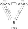
- the terminal device can feed back ACK/NACK and CSI to different TRPs that transmit the corresponding PDSCH (as shown in FIG. 2 ) and can be combined and reported to a TRP (as shown in FIG. 3 ).
- the former can be applied in the condition of ideal backhaul and the condition of non-ideal backhaul, and the latter can be applied in the condition of ideal backhaul.
- the DCI used to schedule PDSCH transmitted by different TRPs can be carried by different CORESETs (Control Resource Sets), that is, multiple CORESETs are configured on the network side.
- CORESETs Control Resource Sets
- Each TRP uses its own CORESET for scheduling, that is, different TRPs can be distinguished by CORESET.
- a network device can configure a CORESET group index for each CORESET, and different indexes correspond to different TRPs.
- the terminal device returns CSI
- the terminal device needs to separately return the corresponding CSI of each TRP.
- the CSI may include RI (Rank Indication).
- RANK is the rank in the antenna matrix in the MIMO scheme, representing N parallel and effective data flows, PMI (Pre-coding Matrix Indication), CQI (Channel Quality Indicator) and other content, and can be used for the scheduling of the respective TRP for downlink transmission.
- PMI Pre-coding Matrix Indication
- CQI Channel Quality Indicator
- the TCI indicating the downlink signal includes the QCL reference signal used to receive the downlink signal.
- the QCL reference signal may be an SSB of the serving cell. If the QCL reference signal SSB and the downlink signal PDSCH/CSI-RS of the serving cell are quasi co-located with respect to QCL type-D, these two signals can be FDM transmitted on the same OFDM symbol.
- the terminal device not only needs to receive downlink signals from the serving cell, but also needs to receive downlink signals from neighboring cells.
- the QCL reference signal of the downlink signal from the neighboring cell may be the SSB from the neighboring cell.
- the embodiment of the disclosure provides a downlink transmission method.
- the terminal device determines the multiplexing mode of the SSB and other downlink signals according to the physical cell identification (PCID) carried by the SSB, thereby supporting the terminal device to receive the SSB sent by the neighboring cell as the QCL reference signal of other downlink signals.
- the terminal device can determine whether the SSB comes from the serving cell or the neighboring cell according to the PCID carried by the SSB. Further, the terminal device determines whether the SSB can be included in the same OFDM symbol for transmission with other downlink signals (downlink data includes, for example, PDSCH and downlink reference signals such as CSI-RS, etc.) and multiplexing mode within the same OFDM symbol. Then, the terminal device can receive the SSB from the neighboring cell as the QCL reference signal of other downlink signals based on the determined multiplexing mode, so as to better support the multi-TRP transmission between cells.
- PCID physical cell identification
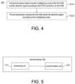
- FIG. 4 is a schematic flowchart of a downlink transmission method 200 according to an embodiment of the disclosure. This method can be optionally applied to the system shown in FIG. 1 , but is not limited thereto. The method includes at least steps S210 and S220 as explained in the following content.
- Step S210 The terminal device determines the multiplexing mode of the first SSB and the downlink signal according to the PCID (Physical Cell Identification) carried by the first SSB.
- PCID Physical Cell Identification
- Step S220 The terminal device receives the first SSB and the downlink signal according to the multiplexing mode.
- the first SSB may be used as the downlink reference signal or the QCL reference signal of the downlink channel.
- the downlink signal may be other downlink signals except the first SSB.
- the downlink signal includes but is not limited to CSI-RS, PDSCH (Physical Downlink Shared Channel), SSB or PDCCH (Physical Downlink Control Channel), etc.
- the terminal device can first determine whether the first SSB comes from the serving cell or the neighboring cell. There are many determining methods. For example, it can be determined whether the PCID carried by the first SSB is the same as the PCID carried by the SSB used to obtain the MIB (Master Information Block).
- MIB Master Information Block
- the first SSB comes from the serving cell. If they are different, it means that the first SSB comes from the neighboring cell. In another example, it can be determined whether the PCID carried by the first SSB is the same as the serving cell ID (Identification). If they are the same, it means that the first SSB comes from the serving cell. If they are different, it means that the first SSB comes from the neighboring cell. Still in another example, it can be determined whether the PCID carried by the first SSB is the same as the PCID carried by the second SSB. If they are the same, it means they are from the same cell. If they are different, it means they are from different cells.
- the terminal device Before receiving the first SSB and the downlink signal, the terminal device can obtain the PCID carried by the first SSB, and can also obtain the PCID carried by the SSB used to obtain the MIB, the serving cell ID, and the PCID carried by the second SSB. For example, the terminal device obtains the PCID carried in the SSB in the QCL reference signal from the network side through high-level signaling. In another example, the terminal device detects the SSB by itself to determine the PCID carried by the SSB used to obtain the MIB, the serving cell ID and other information.
- step S210 when the downlink signal is a PDSCH or a CSI-RS configured with a repetition coefficient, in step S210, it can be determined whether the PCID carried by the first SSB is the same as the PCID carried by the SSB used to obtain the MIB. If they are the same, it means that the first SSB comes from the serving cell. If they are different, it means that the first SSB comes from the neighboring cell. Then the terminal device determines the multiplexing mode of the first SSB and the downlink signal according to the determining result. If the first SSB comes from the neighboring cell, the first SSB can support simultaneous reception of the first SSB and downlink signals.
- the first SSB comes from the serving cell, it can support simultaneous reception of the first SSB and the downlink signal when certain conditions are met, such as the QCL type-D (type D) quasi co-location of the first SSB and the downlink signal. Specifically, one or more of the following conditions 1 to 3 may be involved.
- Condition 1 In the case that the PCID carried by the first SSB is different from the PCID carried by the SSB used to obtain the MIB, it is determined that the multiplexing mode is: the first SSB and the downlink signal support transmission on the same OFDM (Orthogonal Frequency Division Multiplexing) symbol.
- OFDM Orthogonal Frequency Division Multiplexing
- the multiplexing mode is: when the first SSB and the downlink signal are quasi co-located with respect to QCL type-D, the first SSB and the downlink signal support transmission in different PRBs (Physical Resource Blocks) on the same OFDM symbol.
- PRBs Physical Resource Blocks
- the transmission mode in different PRBs on the same OFDM symbol may also be referred to as FDM (Frequency-division multiplexing) mode.
- Condition 3 In the case that the PCID carried by the first SSB is the same as the PCID carried by the SSB used to obtain the MIB, it is determined that the multiplexing mode is: when the first SSB and the downlink signal are not quasi co-located with respect to QCL type-D, the first SSB and the downlink signal are transmitted on different OFDM symbols.
- the transmission mode on different OFDM symbols may also be referred to as a TDM (Time Division Multiplexing) mode.
- the condition where the first SSB and the downlink signal are not quasi co-located with respect to QCL type-D may include: the first SSB and the downlink signal do not have a quasi co-location relationship, or the quasi co-location relationship between the first SSB and the downlink signal is other types instead of QCL type-D.
- step S210 when the downlink signal is a PDSCH or a CSI-RS configured with a repetition coefficient, in step S210, it may also be determined whether the PCID carried by the first SSB is the same as the serving cell ID. If they are the same, it means that the first SSB comes from the serving cell. If they are different, it means that the first SSB comes from the neighboring cell. Then the terminal device determines the multiplexing mode of the first SSB and the downlink signal according to the determining result. If the first SSB comes from the neighboring cell, it can support simultaneous reception of the first SSB and downlink signals.
- the first SSB comes from the serving cell, it can support simultaneous reception of the first SSB and the downlink signal when certain conditions are met, such as the QCL type-D quasi co-location of the first SSB and the downlink signal. Specifically, one or more of the following conditions 4 to 6 may be involved.
- Condition 4 In the case that the PCID carried by the first SSB is not the serving cell ID, it is determined that the multiplexing mode is: the first SSB and the downlink signal support transmission on the same OFDM symbol.
- Condition 5 In the case that the PCID carried by the first SSB is the serving cell ID, it is determined that the multiplexing mode is: in the case that the first SSB and the downlink signal are quasi co-located with respect to QCL type-D, the first SSB and the downlink signal support transmission in different PRBs on the same OFDM symbol.
- Condition 6 In the case that the PCID carried by the first SSB is the serving cell ID, it is determined that the multiplexing mode is: in the case that the first SSB and the downlink signal are not quasi co-located with respect to QCL type-D, the first SSB and the downlink signal are transmitted on different OFDM symbols.
- the terminal device determines the multiplexing mode of the first SSB and the downlink signal according to the determining result. If the first SSB comes from the neighboring cell, it can support simultaneous reception of the first SSB and downlink signals. If the first SSB comes from the serving cell, it does not support simultaneous reception of the first SSB and downlink signals. Specifically, one or more of the following conditions 7 and 8 may be involved.
- Condition 7 In the case that the PCID carried by the first SSB is different from the PCID carried by the SSB used to obtain the MIB, it is determined that the multiplexing mode is: the first SSB and the downlink signal support transmission on the same OFDM symbol.
- Condition 8 In the case that the PCID carried by the first SSB is the same as the PCID carried by the SSB used to obtain the MIB, it is determined that the multiplexing mode is: the first SSB and the downlink signal are transmitted on different OFDM symbols.
- the terminal device determines the multiplexing mode of the first SSB and the downlink signal according to the determining result. If the first SSB comes from the neighboring cell, it can support simultaneous reception of the first SSB and downlink signal. If the first SSB comes from the serving cell, it does not support simultaneous reception of the first SSB and downlink signal. Specifically, one or more of the following conditions 9 and 10 may be involved.
- Condition 9 In the case that the PCID carried by the first SSB is not the serving cell ID, it is determined that the multiplexing mode is: the first SSB and the downlink signal support transmission on the same OFDM symbol.
- Condition 10 In the case that the PCID carried by the first SSB is the serving cell ID, it is determined that the multiplexing mode is: the first SSB and the downlink signal are transmitted on different OFDM symbols.
- the downlink signal is a PDCCH (Physical Downlink Control Channel) or a CSI-RS with no repetition coefficient configured.
- the terminal device determines the multiplexing mode of the first SSB and the second SSB according to the determining result, which may include one or more of the following conditions 11 to 14.
- the first SSB and the second SSB are different SSBs.
- different SSB means two different signals, that is, the information carried by them is not completely the same, or the information carried by them is completely different.
- Condition 11 In the case that the PCID carried by the first SSB is different from the PCID carried by the second SSB, it is determined that the multiplexing mode is: in the case that the SSB indexes carried by the first SSB and the second SSB are different, the first SSB and the second SSB support transmission on the same OFDM symbol.
- Condition 12 In the case that the PCID carried by the first SSB is different from the PCID carried by the second SSB, it is determined that the multiplexing mode is: in the case that the SSB indexes carried by the first SSB and the second SSB are the same, the first SSB and the second SSB are transmitted on different OFDM symbols.
- Condition 13 In the case that the PCID carried by the first SSB is different from the PCID carried by the second SSB, it is determined that the multiplexing mode is: the first SSB and the second SSB support transmission on the same OFDM symbol.
- Condition 14 In the case that the PCID carried by the first SSB is the same as the PCID carried by the second SSB, it is determined that the multiplexing mode is: the first SSB and the second SSB are transmitted on different OFDM symbols.
- the first SSB and the downlink signal support transmission on the same OFDM symbol, which means that the first SSB and the downlink signal are transmitted on the same OFDM symbol or on different OFDM symbols.
- the multiplexing mode determined according to the above-mentioned condition 2 or condition 5 is: in the case that the first SSB and the downlink signal are quasi co-located with respect to QCL type-D, the first SSB and the downlink signal supports transmission in different PRBs on the same OFDM symbol.
- the terminal device receives the first SSB and/or the downlink signal according to the multiplexing mode, including: in the condition that the SSB and the downlink signal are quasi co-located with respect to QCL type-D, the terminal device receives the first SSB and the downlink signal in different PRBs on the same OFDM symbol, or receives the first SSB and the downlink signal on different OFDM symbols.
- the multiplexing mode determined according to the foregoing condition 3 or condition 6 is: in the case that the first SSB and the downlink signal are not quasi co-located with respect to QCL type-D, the first SSB and the downlink signal are transmitted on different OFDM symbols.
- the terminal device receives the first SSB and/or the downlink signal according to the multiplexing mode, including: in the case that the SSB and the downlink signal are not quasi co-located with respect to QCL type-D, the terminal device receives the first SSB and the downlink signal on different OFDM symbols.
- the multiplexing mode determined according to the above condition 11 is: in the case that the SSB indexes carried by the first SSB and the second SSB are different, the first SSB and the second SSB support transmission on the same OFDM symbol.
- the terminal device receives the first SSB and/or the downlink signal according to the multiplexing mode, including: in the case that the SSB indexes carried by the first SSB and the second SSB are different, the terminal device receives the first SSB and the second SSB on the same or different OFDM symbols.
- the multiplexing mode determined according to the above condition 12 is: in the case that the SSB indexes carried by the first SSB and the second SSB are the same, the first SSB and the second SSB are transmitted on different OFDM symbols.
- the terminal device receives the first SSB and/or the downlink signal according to the multiplexing mode, including: in the case that the SSB indexes carried by the first SSB and the second SSB are the same, the terminal device receives the first SSB and the downlink signal on different OFDM symbols.
- condition 4 when the multiplexing mode is determined according to the above condition 1, condition 4, condition 7, condition 9 or condition 13 is: the first SSB and the downlink signal support transmission on the same OFDM symbol.
- the terminal device receives the first SSB and the downlink signal according to the multiplexing mode, including: the terminal device receives the first SSB and the downlink signal on the same or different OFDM symbols.
- condition 10 when the multiplexing mode is determined according to the above condition 8, condition 10, or condition 14 is: the first SSB and the downlink signal are transmitted on different OFDM symbols.
- the terminal device receives the first SSB and the downlink signal according to the multiplexing mode, including: the terminal device receives the first SSB and the downlink signal on different OFDM symbols.
- the PCID carried by the first SSB is used to determine the multiplexing mode of the first SSB and the downlink signal, so as to support the multiplexing of the SSB from different cells and other downlink signals.
- the terminal device is configured to determine whether the SSB is from the serving cell or the neighboring cell according to the PCID carried by the SSB, and further determine whether the SSB and the downlink signal are transmitted on the same OFDM symbol, and determine the multiplexing mode in the same OFDM symbol. Then the terminal device receives the SSB from the neighboring cell as the QCL reference signal of other downlink signals based on the determined multiplexing mode, thereby realizing the multiplexing of the SSB from the neighboring cell and the downlink signal from the serving cell, thus better supporting multi-TRP transmission between cells.
- the downlink transmission method of this embodiment includes the following steps:
- the downlink transmission method of this embodiment includes the following steps:
- the downlink transmission method of this embodiment includes the following steps:
- the terminal device can determine whether the SSB is from the serving cell or the neighboring cell according to the PCID carried by the SSB, and further determine whether the SSB and the downlink data as well as the downlink reference signal can be transmitted on the same OFDM symbol, and determine the multiplexing mode in the same OFDM symbol. As such, the terminal device can receive the SSB from the neighboring cell as the QCL reference signal of other downlink signals, thereby better supporting multi-TRP transmission between cells.
- FIG. 5 is a schematic block diagram of a terminal device 300 according to an embodiment of the disclosure.
- the terminal device 300 inlcudes:
- a processing unit 310 is configured to determine the multiplexing mode of the first SSB and the downlink signal according to the PCID carried by the first SSB.
- a communication unit 320 is configured to receive the first SSB and the downlink signal according to the multiplexing mode.
- the processing unit 310 is further configured to: in the case that the PCID carried by the first SSB is different from the PCID carried by the SSB used to obtain the MIB, determine that the multiplexing mode is: the first SSB and the downlink signal support transmission on the same OFDM symbol.
- the processing unit 310 is further configured to: in the case that the PCID carried by the first SSB is the same as the PCID carried by the SSB used to obtain the MIB, determine that the multiplexing mode is: in the case that the first SSB and the downlink signal are quasi co-located with respect to QCL type-D, the first SSB and the downlink signal support transmission in different PRBs on the same OFDM symbol.
- the downlink signal is a physical downlink shared channel PDSCH or a channel state information reference signal CSI-RS configured with a repetition coefficient.
- the processing unit 310 may further be configured to: in the case that the PCID carried by the first SSB is the same as the PCID carried by the SSB used to obtain the MIB, determine that the multiplexing mode is: in the case that the first SSB and the downlink signal are not quasi co-located with respect to QCL type-D, the first SSB and the downlink signal are transmitted on different OFDM symbols.
- the processing unit 310 may further be configured to: in the case that the PCID carried by the first SSB is not the serving cell ID, determine that the multiplexing mode is: the first SSB and the downlink signal support transmission on the same OFDM symbol.
- the processing unit 310 may further be configured to: in the case that the PCID carried by the first SSB is the serving cell ID, determine that the multiplexing mode is: in the case that the first SSB and the downlink signal are quasi co-located with respect to QCL type-D, the first SSB and the downlink signal support transmission in different PRBs on the same OFDM symbol.
- the processing unit 310 may further be configured to: in the case that the PCID carried by the first SSB is the serving cell ID, determine that the multiplexing mode is: in the case that the first SSB and the downlink signal are not quasi co-located with respect to QCL type-D, the first SSB and the downlink signal are transmitted on different OFDM symbols.
- the downlink signal is a physical downlink control channel PDCCH or a CSI-RS with no repetition coefficient configured.
- the processing unit 310 may further be configured to: in the case that the PCID carried by the first SSB is different from the PCID carried by the SSB used to obtain the MIB, determine that the multiplexing mode is: the first SSB and the downlink signal support transmission on the same OFDM symbol.
- the processing unit 310 may further be configured to: in the case that the PCID carried by the first SSB is the same as the PCID carried by the SSB used to obtain the MIB, determine that the multiplexing mode is: the first SSB and the downlink signal are transmitted on different OFDM symbols.
- the processing unit 310 may further be configured to: in the case that the PCID carried by the first SSB is not the serving cell ID, determine that the multiplexing mode is: the first SSB and the downlink signal support transmission on the same OFDM symbol.
- the processing unit 310 may further be configured to: in the case that the PCID carried by the first SSB is the serving cell ID, determine that the multiplexing mode is: the first SSB and the downlink signal are transmitted on different OFDM symbols.
- the processing unit 310 may further be configured to: in the case that the PCID carried by the first SSB is different from the PCID carried by the second SSB, determine that the multiplexing mode is: in the case that the SSB indexes carried by the first SSB and the second SSB are different, the first SSB and the second SSB support transmission on the same OFDM symbol.
- the processing unit 310 may further be configured to: in the case that the PCID carried by the first SSB is different from the PCID carried by the second SSB, determine that the multiplexing mode is: in the case that the SSB indexes carried by the first SSB and the second SSB are the same, the first SSB and the second SSB are transmitted on different OFDM symbols.
- the processing unit 310 may further be configured to: in the case that the PCID carried by the first SSB is different from the PCID carried by the second SSB, determine that the multiplexing mode is: the first SSB and the second SSB support transmission on the same OFDM symbol.
- the processing unit 310 may further be configured to: in the case that the PCID carried by the first SSB is the same as the PCID carried by the second SSB, determine that the multiplexing mode is: the first SSB and the second SSB are transmitted on different OFDM symbols.
- the multiplexing mode determined by the processing unit 310 is: in the case that the first SSB and the downlink signal are quasi co-located with respect to QCL type-D, the first SSB and the downlink signal support transmission in different PRBs on the same OFDM symbol.
- the communication unit 320 is further configured to: in the case that the first SSB and the downlink signal are quasi co-located with respect to QCL type-D, receive the first SSB and the downlink signal in different PRBs on the same OFDM symbol, or receive the first SSB and the downlink signal on different OFDM symbols.
- the multiplexing mode determined by the processing unit 310 is: in the case that the first SSB and the downlink signal are not quasi co-located with QCL type-D, the first SSB and the downlink signal are transmitted on different OFDM symbols.
- the communication unit 320 is further configured to: in the case that the first SSB and the downlink signal are not quasi co-located with respect to QCL type-D, receive the first SSB and the downlink signal on different OFDM symbols.
- the multiplexing mode determined by the processing unit 310 is: in the case that the SSB indexes carried by the first SSB and the second SSB are different, the first SSB and the second SSB support transmission on the same OFDM symbol.
- the communication unit 320 is further configured to: in the case that the SSB indexes carried by the first SSB and the second SSB are different, receive the first SSB and the second SSB on the same or different OFDM symbols.
- the multiplexing mode determined by the processing unit 310 is: in the case that the SSB indexes carried by the first SSB and the second SSB are the same, the first SSB and the second SSB are transmitted on different OFDM symbols.
- the communication unit 320 is further configured to: in the case that the SSB indexes carried by the first SSB and the second SSB are the same, receive the first SSB and the second SSB on different OFDM symbols.
- the multiplexing mode determined by the processing unit 310 is that the first SSB and the downlink signal support transmission on the same OFDM symbol.
- the communication unit 320 is further configured to: receive the first SSB and the downlink signal on the same or different OFDM symbols.
- the multiplexing mode determined by the processing unit 310 is that the first SSB and the downlink signal are transmitted on different OFDM symbols.
- the communication unit 320 is further configured to: receive the first SSB and the downlink signal on different OFDM symbols.
- FIG. 6 is a schematic structural diagram of a communication device 600 according to an embodiment of the disclosure.
- the communication device 600 shown in FIG. 6 includes a processor 610, and the processor 610 can invoke and run a computer program in the memory to implement the method in the embodiment of the disclosure.
- the communication device 600 may further include a memory 620.
- the processor 610 can invoke and run a computer program in the memory 620 to implement the method in the embodiment of the disclosure.
- the memory 620 may be a separate device independent of the processor 610, or may be integrated in the processor 610.
- the communication device 600 may further include a transceiver 630, and the processor 610 may control the transceiver 630 to communicate with other devices.
- the transceiver 630 may send information or data to other devices, or receive information or data sent by other devices.
- the transceiver 630 may include a transmitter and a receiver.
- the transceiver 630 may further include an antenna, and the number of antennas may be one or more.
- the communication device 600 may be a network device in an embodiment of the disclosure, and the communication device 600 may implement corresponding processes implemented by the network device in various methods in the embodiments of the disclosure. For conciseness, no further details are not described herein.
- the communication device 600 may be a terminal device in an embodiment of the disclosure, and the communication device 600 may implement the corresponding processes implemented by the terminal device in various methods in the embodiments of the disclosure. For conciseness, no further details are not described herein.
- FIG. 7 is a schematic structural diagram of a chip 700 according to an embodiment of the disclosure.
- the chip 700 shown in FIG. 7 includes a processor 710, and the processor 710 is configured to invoke and run a computer program in the memory to implement the method in the embodiment of the disclosure.
- the chip 700 may further include a memory 720.
- the processor 710 can invoke and run a computer program in the memory 720 to implement the method in the embodiment of the disclosure.
- the memory 720 may be a separate device independent of the processor 710, or may be integrated in the processor 710.
- the chip 700 may further include an input interface 730.
- the processor 710 can control the input interface 730 to communicate with other devices or chips, and specifically, can obtain information or data sent by other devices or chips.
- the chip 700 may further include an output interface 740.
- the processor 710 can control the output interface 740 to communicate with other devices or chips, specifically, can output information or data to other devices or chips.
- the chip can be applied to the network device in the embodiments of the disclosure, and the chip can implement the corresponding processes implemented by the network device in the various methods in the embodiments of the disclosure.
- the chip can implement the corresponding processes implemented by the network device in the various methods in the embodiments of the disclosure.
- the chip can be applied to the terminal device in the embodiment of the disclosure, and the chip can implement the corresponding process implemented by the terminal device in various methods in the embodiment of the disclosure.
- the chip can implement the corresponding process implemented by the terminal device in various methods in the embodiment of the disclosure.
- the chip mentioned in the embodiment of the disclosure may also be referred to as a system-level chip, a system chip, a chip system, or a system-on-chip.
- the processors described above may be general-purpose processors, digital signal processors (DSP), field programmable gate arrays (FPGAs), application specific integrated circuits (ASICs) or other programmable logic devices, transistor logic devices, discrete hardware components, etc.
- DSP digital signal processors
- FPGA field programmable gate arrays
- ASIC application specific integrated circuits
- the aforementioned general-purpose processor may be a microprocessor or any conventional processor.
- non-volatile memory may be volatile memory or non-volatile memory, or may include both volatile and non-volatile memory.
- non-volatile memory can be Read-Only Memory (ROM), Programmable ROM (PROM), Erasable PROM (EPROM), Electrically EPROM (EEPROM) or flash memory.
- ROM Read-Only Memory
- PROM Programmable ROM
- EPROM Erasable PROM
- EEPROM Electrically EPROM
- flash memory may be a Random Access Memory (RAM).
- RAM Random Access Memory
- the above-mentioned memory is exemplary but not limited thereto.
- the memory in the embodiment of the disclosure may also be static RAM (SRAM), dynamic RAM (DRAM), synchronous DRAM (SDRAM), double data rate SDRAM (DDR SDRAM), enhanced SDRA (ESDRAM), synch link DRAM (SLDRAM), and Direct Rambus RAM (DR RAM), etc. That is to say, the memory in the embodiments of the disclosure is intended to include but not limited to these and any other types of memory applicable.
- FIG. 8 is a schematic block diagram of a communication system 800 embodied in an embodiment of the disclosure. As shown in FIG. 8 , the communication system 800 includes a terminal device 810 and a network device 820.
- the terminal device 810 determines the multiplexing mode of the first SSB and the downlink signal according to the PCID carried by the first SSB, and receives the first SSB and/or the downlink signal according to the multiplexing mode.
- the terminal device 810 can be used to implement the corresponding functions implemented by the terminal device in the above method
- the network device 820 can be used to implement the corresponding functions implemented by the network device in the above method.
- the above embodiments may be implemented as a whole or in part by software, hardware, firmware, or any combination thereof.
- the above embodiments are implemented by software, they can be implemented as a whole or in part in the form of a computer program product.
- the computer program product includes one or more computer instructions.
- the computer can be a general-purpose computer, a specific-purpose computer, a computer network, or other programmable devices.
- the computer instruction can be stored in a computer-readable storage medium, or transmitted from one computer-readable storage medium to another computer-readable storage medium.
- the computer instruction can be transmitted from a website, a computer, a server, or a data center to another website, computer, server or data center in a wired manner (such as coaxial cable, optical fiber, Digital Subscriber Line (DSL)) or a wireless manner (such as infrared, wireless, microwave, etc.).
- the computer-readable storage medium may be any available medium that can be accessed by a computer or a data storage device such as a server or data center integrated with one or more available media.
- the usable medium may be a magnetic medium (for example, a floppy disk, a hard disk, and a magnetic tape), an optical medium (for example, a DVD), or a semiconductor medium (for example, a Solid State Disk (SSD)) and so on.
Landscapes
- Engineering & Computer Science (AREA)
- Signal Processing (AREA)
- Computer Networks & Wireless Communication (AREA)
- Mobile Radio Communication Systems (AREA)
Claims (7)
- Downlink-Übertragungsverfahren, umfassend:
Bestimmen (S210), durch ein Endgerät (300), eines Multiplexmodus eines ersten Synchronisationssignalblocks, SSB, und eines Downlink-Signals in Abhängigkeit davon, ob der erste SSB von einer bedienenden Zelle oder von einer benachbarten Zelle stammt, wobei die Tatsache, ob der erste SSB von einer bedienenden Zelle oder von einer benachbarten Zelle stammt, gemäß einer "Physical Cell Identification", PCID, die vom ersten SSB getragen wird, bestimmt wird, wobei der Schritt des Bestimmens (S210) des Multiplexmodus umfasst:in dem Fall, dass der erste SSB nicht von der bedienenden Zelle stammt, Bestimmen, dass der Multiplexmodus wie folgt ist: der erste SSB und das Downlink-Signal unterstützen eine Übertragung auf dem gleichen "Orthogonal Frequency Division Multiplexing"-, OFDM-, Symbol; undin dem Fall, dass der erste SSB von der bedienenden Zelle stammt, Bestimmen, dass der Multiplexmodus wie folgt ist: der erste SSB und das Downlink-Signal werden auf verschiedenen OFDM-Symbolen übertragen;Empfangen (S220), durch das Endgerät (300), des Downlink-Signals gemäß dem Multiplexmodus, umfassend:in dem Fall, dass der Multiplexmodus die Übertragung auf dem gleichen OFDM-Symbol unterstützt,das Endgerät (300) den ersten SSB und das Downlink-Signal auf dem gleichen oder auf verschiedenen OFDM-Symbolen empfängt, und das Endgerät (300) den Empfang des ersten SSB und des Downlink-Signals auf dem gleichen OFDM-Symbol unterstützt und auch den Empfang des ersten SSB und des Downlink-Signals auf verschiedenen OFDM-Symbolen unterstützt. - Verfahren nach Anspruch 1, wobei das Downlink-Signal ein "Physical Downlink Shared Channel", PDSCH, oder ein "Channel State Information Reference Signal", CSI-RS, ist, das mit einem Wiederholungskoeffizienten ausgelegt ist.
- Verfahren nach Anspruch 1, wobei, wenn der Multiplexmodus die Übertragung auf verschiedenen OFDM-Symbolen unterstützt, das Endgerät (300) den ersten SSB und das Downlink-Signal auf verschiedenen OFDM-Symbolen empfängt.
- Endgerät (300), umfassend: einen Prozessor (610) und einen Speicher (620), wobei der Speicher (620) dafür ausgelegt ist, ein Computerprogramm zu speichern, und der Prozessor (610) dafür ausgelegt ist, das im Speicher (620) gespeicherte Computerprogramm aufzurufen und auszuführen, wobei das Computerprogramm Anweisungen umfasst, die bei ihrer Ausführung durch den Prozessor das Endgerät veranlassen, die folgenden Schritte durchzuführen:
Bestimmen eines Multiplexmodus eines ersten Synchronisationssignalblocks, SSB, und eines Downlink-Signals in Abhängigkeit davon, ob der erste SSB von einer bedienenden Zelle oder von einer benachbarten Zelle stammt, wobei die Tatsache, ob der erste SSB von einer bedienenden Zelle oder von einer benachbarten Zelle stammt, gemäß einer "Physical Cell Identification", PCID, die vom ersten SSB getragen wird, bestimmt wird, wobei der Schritt des Bestimmens (S210) des Multiplexmodus umfasst:in dem Fall, dass der erste SSB nicht von der bedienenden Zelle stammt, Bestimmen, dass der Multiplexmodus wie folgt ist: der erste SSB und das Downlink-Signal unterstützen eine Übertragung auf dem gleichen "Orthogonal Frequency Division Multiplexing"-, OFDM-, Symbol; undin dem Fall, dass der erste SSB von der bedienenden Zelle stammt, Bestimmen, dass der Multiplexmodus wie folgt ist: der erste SSB und das Downlink-Signal werden auf verschiedenen OFDM-Symbolen übertragen;Empfangen des Downlink-Signals gemäß dem Multiplexmodus, umfassend:in dem Fall, dass der Multiplexmodus die Übertragung auf dem gleichen OFDM-Symbol unterstützt,das Endgerät (300) den ersten SSB und das Downlink-Signal auf dem gleichen oder auf verschiedenen OFDM-Symbolen empfängt, und das Endgerät (300) den Empfang des ersten SSB und des Downlink-Signals auf dem gleichen OFDM-Symbol unterstützt und auch den Empfang des ersten SSB und des Downlink-Signals auf verschiedenen OFDM-Symbolen unterstützt. - Endgerät (300) nach Anspruch 4, wobei das Downlink-Signal ein "Physical Downlink Shared Channel", PDSCH, oder ein "Channel State Information Reference Signal", CSI-RS, ist, das mit einem Wiederholungskoeffizienten ausgelegt ist.
- Endgerät (300) nach Anspruch 4, wobei, wenn der Multiplexmodus die Übertragung auf verschiedenen OFDM-Symbolen unterstützt, das Endgerät (300) den ersten SSB und das Downlink-Signal auf verschiedenen OFDM-Symbolen empfängt.
- Computerlesbares Speichermedium, umfassend ein Computerprogramm, das bei seiner Ausführung durch einen Computer den Computer veranlasst, das Verfahren nach Anspruch 1 durchzuführen.
Applications Claiming Priority (1)
| Application Number | Priority Date | Filing Date | Title |
|---|---|---|---|
| PCT/CN2020/075141 WO2021159413A1 (zh) | 2020-02-13 | 2020-02-13 | 下行传输方法和终端设备 |
Publications (3)
| Publication Number | Publication Date |
|---|---|
| EP3985908A1 EP3985908A1 (de) | 2022-04-20 |
| EP3985908A4 EP3985908A4 (de) | 2022-10-19 |
| EP3985908B1 true EP3985908B1 (de) | 2024-03-27 |
Family
ID=77291376
Family Applications (1)
| Application Number | Title | Priority Date | Filing Date |
|---|---|---|---|
| EP20919297.0A Active EP3985908B1 (de) | 2020-02-13 | 2020-02-13 | Downlink-übertragungsverfahren und endgerät |
Country Status (4)
| Country | Link |
|---|---|
| US (1) | US12149457B2 (de) |
| EP (1) | EP3985908B1 (de) |
| CN (2) | CN113632409A (de) |
| WO (1) | WO2021159413A1 (de) |
Families Citing this family (2)
| Publication number | Priority date | Publication date | Assignee | Title |
|---|---|---|---|---|
| US11627505B2 (en) | 2019-11-18 | 2023-04-11 | Samsung Electronics Co., Ltd. | Method and apparatus for beam management for inter-cell mobility |
| WO2022236566A1 (en) * | 2021-05-10 | 2022-11-17 | Apple Inc. | Cmr and imr configuration enhancement for multi-trp csi-rs reporting |
Family Cites Families (8)
| Publication number | Priority date | Publication date | Assignee | Title |
|---|---|---|---|---|
| US11496976B2 (en) * | 2017-03-24 | 2022-11-08 | Telefonaktiebolaget Lm Ericsson (Publ) | Method and device for synchronization in a wireless communication system |
| WO2019017751A1 (ko) * | 2017-07-21 | 2019-01-24 | 엘지전자 주식회사 | 무선 통신 시스템에서 채널 상태 정보 참조 신호를 송수신하는 방법 및 이를 위한 장치 |
| US10681715B2 (en) * | 2018-04-04 | 2020-06-09 | Qualcomm Incorporated | Control information combining techniques in wireless communications |
| US10952235B2 (en) * | 2018-04-05 | 2021-03-16 | Qualcomm Incorporated | Resource identification techniques for combining multiple instances of system information |
| EP3609088A1 (de) * | 2018-08-06 | 2020-02-12 | Intel Corporation | Techniken zur analogen strahlformung |
| US11502800B2 (en) * | 2019-08-13 | 2022-11-15 | Huawei Technologies Co., Ltd. | Methods and apparatuses for configuration of sounding reference signal for serving and neighboring cell measurements |
| US11553489B2 (en) * | 2019-10-30 | 2023-01-10 | Qualcomm Incorporated | SFN transmission procedure for FR2 |
| US11637669B2 (en) * | 2019-11-25 | 2023-04-25 | Qualcomm Incorporated | Single frequency network transmission procedure based on sounding reference signals |
-
2020
- 2020-02-13 WO PCT/CN2020/075141 patent/WO2021159413A1/zh not_active Ceased
- 2020-02-13 CN CN202080024328.0A patent/CN113632409A/zh active Pending
- 2020-02-13 CN CN202111342006.3A patent/CN114126063B/zh active Active
- 2020-02-13 EP EP20919297.0A patent/EP3985908B1/de active Active
-
2022
- 2022-02-16 US US17/673,723 patent/US12149457B2/en active Active
Also Published As
| Publication number | Publication date |
|---|---|
| CN113632409A (zh) | 2021-11-09 |
| CN114126063A (zh) | 2022-03-01 |
| EP3985908A4 (de) | 2022-10-19 |
| WO2021159413A1 (zh) | 2021-08-19 |
| CN114126063B (zh) | 2023-08-08 |
| US12149457B2 (en) | 2024-11-19 |
| EP3985908A1 (de) | 2022-04-20 |
| US20220173847A1 (en) | 2022-06-02 |
Similar Documents
| Publication | Publication Date | Title |
|---|---|---|
| JP7645309B2 (ja) | リソース構成方法および装置 | |
| CN111435845B (zh) | 通信方法和通信装置 | |
| US20230361814A1 (en) | Transmission of NR Control Information in an LTE Downlink Subframe | |
| US11870718B2 (en) | Sidelink CSI report transmission methods and conditions | |
| US12457608B2 (en) | Wireless communication method, terminal device, and network device | |
| CN113490278A (zh) | 下行信号传输的方法和设备 | |
| US20230209587A1 (en) | Interference mitigation negotiation between network entities | |
| US12149457B2 (en) | Downlink transmission method and terminal device | |
| CN110166204B (zh) | 资源分配的方法和装置 | |
| WO2022147824A1 (en) | User equipment initiated panel status reporting | |
| JP2023545055A (ja) | 無線通信方法、装置及びシステム | |
| US12598615B2 (en) | Enhancing aperiodic or semi-periodic channel state information (CSI) multiplexing on multiple physical uplink shared channel (PUSCH) repetitions | |
| US11909496B2 (en) | Beam switching in near-field operations | |
| US20230058859A1 (en) | Wireless transmission reception point (trp) information exchange | |
| US20230058050A1 (en) | Acquiring location information of an assisting transmission and reception point (trp) | |
| US20210204235A1 (en) | Synchronization signal block (ssb) configuration for power management | |
| US12133208B2 (en) | Method and devices for wireless communication | |
| CN116671054A (zh) | 确定信道状态信息的方法、终端设备和网络设备 | |
| WO2020197863A1 (en) | Full dimension multiple-input multiple-output baseband capability indication | |
| CN119586049A (zh) | 无线通信方法及装置、终端设备、网络设备 | |
| US11616604B2 (en) | Replacing broken uplink repetitions | |
| CN116210189B (zh) | 确定传输使用的天线面板的方法和终端设备 |
Legal Events
| Date | Code | Title | Description |
|---|---|---|---|
| STAA | Information on the status of an ep patent application or granted ep patent |
Free format text: STATUS: THE INTERNATIONAL PUBLICATION HAS BEEN MADE |
|
| PUAI | Public reference made under article 153(3) epc to a published international application that has entered the european phase |
Free format text: ORIGINAL CODE: 0009012 |
|
| STAA | Information on the status of an ep patent application or granted ep patent |
Free format text: STATUS: REQUEST FOR EXAMINATION WAS MADE |
|
| 17P | Request for examination filed |
Effective date: 20220114 |
|
| AK | Designated contracting states |
Kind code of ref document: A1 Designated state(s): AL AT BE BG CH CY CZ DE DK EE ES FI FR GB GR HR HU IE IS IT LI LT LU LV MC MK MT NL NO PL PT RO RS SE SI SK SM TR |
|
| A4 | Supplementary search report drawn up and despatched |
Effective date: 20220920 |
|
| RIC1 | Information provided on ipc code assigned before grant |
Ipc: H04W 52/14 20090101ALI20220914BHEP Ipc: H04B 7/04 20170101ALI20220914BHEP Ipc: H04L 5/00 20060101AFI20220914BHEP |
|
| STAA | Information on the status of an ep patent application or granted ep patent |
Free format text: STATUS: EXAMINATION IS IN PROGRESS |
|
| DAV | Request for validation of the european patent (deleted) | ||
| DAX | Request for extension of the european patent (deleted) | ||
| 17Q | First examination report despatched |
Effective date: 20230426 |
|
| GRAP | Despatch of communication of intention to grant a patent |
Free format text: ORIGINAL CODE: EPIDOSNIGR1 |
|
| STAA | Information on the status of an ep patent application or granted ep patent |
Free format text: STATUS: GRANT OF PATENT IS INTENDED |
|
| INTG | Intention to grant announced |
Effective date: 20231109 |
|
| GRAS | Grant fee paid |
Free format text: ORIGINAL CODE: EPIDOSNIGR3 |
|
| GRAA | (expected) grant |
Free format text: ORIGINAL CODE: 0009210 |
|
| STAA | Information on the status of an ep patent application or granted ep patent |
Free format text: STATUS: THE PATENT HAS BEEN GRANTED |
|
| AK | Designated contracting states |
Kind code of ref document: B1 Designated state(s): AL AT BE BG CH CY CZ DE DK EE ES FI FR GB GR HR HU IE IS IT LI LT LU LV MC MK MT NL NO PL PT RO RS SE SI SK SM TR |
|
| REG | Reference to a national code |
Ref country code: GB Ref legal event code: FG4D |
|
| REG | Reference to a national code |
Ref country code: CH Ref legal event code: EP |
|
| REG | Reference to a national code |
Ref country code: DE Ref legal event code: R096 Ref document number: 602020028129 Country of ref document: DE |
|
| REG | Reference to a national code |
Ref country code: IE Ref legal event code: FG4D |
|
| P01 | Opt-out of the competence of the unified patent court (upc) registered |
Effective date: 20240521 |
|
| PG25 | Lapsed in a contracting state [announced via postgrant information from national office to epo] |
Ref country code: LT Free format text: LAPSE BECAUSE OF FAILURE TO SUBMIT A TRANSLATION OF THE DESCRIPTION OR TO PAY THE FEE WITHIN THE PRESCRIBED TIME-LIMIT Effective date: 20240327 |
|
| REG | Reference to a national code |
Ref country code: LT Ref legal event code: MG9D |
|
| PG25 | Lapsed in a contracting state [announced via postgrant information from national office to epo] |
Ref country code: GR Free format text: LAPSE BECAUSE OF FAILURE TO SUBMIT A TRANSLATION OF THE DESCRIPTION OR TO PAY THE FEE WITHIN THE PRESCRIBED TIME-LIMIT Effective date: 20240628 |
|
| PG25 | Lapsed in a contracting state [announced via postgrant information from national office to epo] |
Ref country code: RS Free format text: LAPSE BECAUSE OF FAILURE TO SUBMIT A TRANSLATION OF THE DESCRIPTION OR TO PAY THE FEE WITHIN THE PRESCRIBED TIME-LIMIT Effective date: 20240627 Ref country code: HR Free format text: LAPSE BECAUSE OF FAILURE TO SUBMIT A TRANSLATION OF THE DESCRIPTION OR TO PAY THE FEE WITHIN THE PRESCRIBED TIME-LIMIT Effective date: 20240327 |
|
| PG25 | Lapsed in a contracting state [announced via postgrant information from national office to epo] |
Ref country code: RS Free format text: LAPSE BECAUSE OF FAILURE TO SUBMIT A TRANSLATION OF THE DESCRIPTION OR TO PAY THE FEE WITHIN THE PRESCRIBED TIME-LIMIT Effective date: 20240627 Ref country code: NO Free format text: LAPSE BECAUSE OF FAILURE TO SUBMIT A TRANSLATION OF THE DESCRIPTION OR TO PAY THE FEE WITHIN THE PRESCRIBED TIME-LIMIT Effective date: 20240627 Ref country code: LT Free format text: LAPSE BECAUSE OF FAILURE TO SUBMIT A TRANSLATION OF THE DESCRIPTION OR TO PAY THE FEE WITHIN THE PRESCRIBED TIME-LIMIT Effective date: 20240327 Ref country code: HR Free format text: LAPSE BECAUSE OF FAILURE TO SUBMIT A TRANSLATION OF THE DESCRIPTION OR TO PAY THE FEE WITHIN THE PRESCRIBED TIME-LIMIT Effective date: 20240327 Ref country code: GR Free format text: LAPSE BECAUSE OF FAILURE TO SUBMIT A TRANSLATION OF THE DESCRIPTION OR TO PAY THE FEE WITHIN THE PRESCRIBED TIME-LIMIT Effective date: 20240628 Ref country code: FI Free format text: LAPSE BECAUSE OF FAILURE TO SUBMIT A TRANSLATION OF THE DESCRIPTION OR TO PAY THE FEE WITHIN THE PRESCRIBED TIME-LIMIT Effective date: 20240327 Ref country code: BG Free format text: LAPSE BECAUSE OF FAILURE TO SUBMIT A TRANSLATION OF THE DESCRIPTION OR TO PAY THE FEE WITHIN THE PRESCRIBED TIME-LIMIT Effective date: 20240327 |
|
| REG | Reference to a national code |
Ref country code: NL Ref legal event code: MP Effective date: 20240327 |
|
| PG25 | Lapsed in a contracting state [announced via postgrant information from national office to epo] |
Ref country code: SE Free format text: LAPSE BECAUSE OF FAILURE TO SUBMIT A TRANSLATION OF THE DESCRIPTION OR TO PAY THE FEE WITHIN THE PRESCRIBED TIME-LIMIT Effective date: 20240327 Ref country code: LV Free format text: LAPSE BECAUSE OF FAILURE TO SUBMIT A TRANSLATION OF THE DESCRIPTION OR TO PAY THE FEE WITHIN THE PRESCRIBED TIME-LIMIT Effective date: 20240327 |
|
| PG25 | Lapsed in a contracting state [announced via postgrant information from national office to epo] |
Ref country code: NL Free format text: LAPSE BECAUSE OF FAILURE TO SUBMIT A TRANSLATION OF THE DESCRIPTION OR TO PAY THE FEE WITHIN THE PRESCRIBED TIME-LIMIT Effective date: 20240327 |
|
| REG | Reference to a national code |
Ref country code: AT Ref legal event code: MK05 Ref document number: 1670929 Country of ref document: AT Kind code of ref document: T Effective date: 20240327 |
|
| PG25 | Lapsed in a contracting state [announced via postgrant information from national office to epo] |
Ref country code: NL Free format text: LAPSE BECAUSE OF FAILURE TO SUBMIT A TRANSLATION OF THE DESCRIPTION OR TO PAY THE FEE WITHIN THE PRESCRIBED TIME-LIMIT Effective date: 20240327 |
|
| PG25 | Lapsed in a contracting state [announced via postgrant information from national office to epo] |
Ref country code: IS Free format text: LAPSE BECAUSE OF FAILURE TO SUBMIT A TRANSLATION OF THE DESCRIPTION OR TO PAY THE FEE WITHIN THE PRESCRIBED TIME-LIMIT Effective date: 20240727 |
|
| PG25 | Lapsed in a contracting state [announced via postgrant information from national office to epo] |
Ref country code: PT Free format text: LAPSE BECAUSE OF FAILURE TO SUBMIT A TRANSLATION OF THE DESCRIPTION OR TO PAY THE FEE WITHIN THE PRESCRIBED TIME-LIMIT Effective date: 20240729 Ref country code: SM Free format text: LAPSE BECAUSE OF FAILURE TO SUBMIT A TRANSLATION OF THE DESCRIPTION OR TO PAY THE FEE WITHIN THE PRESCRIBED TIME-LIMIT Effective date: 20240327 |
|
| PG25 | Lapsed in a contracting state [announced via postgrant information from national office to epo] |
Ref country code: ES Free format text: LAPSE BECAUSE OF FAILURE TO SUBMIT A TRANSLATION OF THE DESCRIPTION OR TO PAY THE FEE WITHIN THE PRESCRIBED TIME-LIMIT Effective date: 20240327 |
|
| PG25 | Lapsed in a contracting state [announced via postgrant information from national office to epo] |
Ref country code: CZ Free format text: LAPSE BECAUSE OF FAILURE TO SUBMIT A TRANSLATION OF THE DESCRIPTION OR TO PAY THE FEE WITHIN THE PRESCRIBED TIME-LIMIT Effective date: 20240327 Ref country code: EE Free format text: LAPSE BECAUSE OF FAILURE TO SUBMIT A TRANSLATION OF THE DESCRIPTION OR TO PAY THE FEE WITHIN THE PRESCRIBED TIME-LIMIT Effective date: 20240327 |
|
| PG25 | Lapsed in a contracting state [announced via postgrant information from national office to epo] |
Ref country code: AT Free format text: LAPSE BECAUSE OF FAILURE TO SUBMIT A TRANSLATION OF THE DESCRIPTION OR TO PAY THE FEE WITHIN THE PRESCRIBED TIME-LIMIT Effective date: 20240327 |
|
| PG25 | Lapsed in a contracting state [announced via postgrant information from national office to epo] |
Ref country code: PL Free format text: LAPSE BECAUSE OF FAILURE TO SUBMIT A TRANSLATION OF THE DESCRIPTION OR TO PAY THE FEE WITHIN THE PRESCRIBED TIME-LIMIT Effective date: 20240327 |
|
| PG25 | Lapsed in a contracting state [announced via postgrant information from national office to epo] |
Ref country code: SK Free format text: LAPSE BECAUSE OF FAILURE TO SUBMIT A TRANSLATION OF THE DESCRIPTION OR TO PAY THE FEE WITHIN THE PRESCRIBED TIME-LIMIT Effective date: 20240327 |
|
| PG25 | Lapsed in a contracting state [announced via postgrant information from national office to epo] |
Ref country code: SM Free format text: LAPSE BECAUSE OF FAILURE TO SUBMIT A TRANSLATION OF THE DESCRIPTION OR TO PAY THE FEE WITHIN THE PRESCRIBED TIME-LIMIT Effective date: 20240327 Ref country code: SK Free format text: LAPSE BECAUSE OF FAILURE TO SUBMIT A TRANSLATION OF THE DESCRIPTION OR TO PAY THE FEE WITHIN THE PRESCRIBED TIME-LIMIT Effective date: 20240327 Ref country code: RO Free format text: LAPSE BECAUSE OF FAILURE TO SUBMIT A TRANSLATION OF THE DESCRIPTION OR TO PAY THE FEE WITHIN THE PRESCRIBED TIME-LIMIT Effective date: 20240327 Ref country code: PT Free format text: LAPSE BECAUSE OF FAILURE TO SUBMIT A TRANSLATION OF THE DESCRIPTION OR TO PAY THE FEE WITHIN THE PRESCRIBED TIME-LIMIT Effective date: 20240729 Ref country code: PL Free format text: LAPSE BECAUSE OF FAILURE TO SUBMIT A TRANSLATION OF THE DESCRIPTION OR TO PAY THE FEE WITHIN THE PRESCRIBED TIME-LIMIT Effective date: 20240327 Ref country code: IS Free format text: LAPSE BECAUSE OF FAILURE TO SUBMIT A TRANSLATION OF THE DESCRIPTION OR TO PAY THE FEE WITHIN THE PRESCRIBED TIME-LIMIT Effective date: 20240727 Ref country code: ES Free format text: LAPSE BECAUSE OF FAILURE TO SUBMIT A TRANSLATION OF THE DESCRIPTION OR TO PAY THE FEE WITHIN THE PRESCRIBED TIME-LIMIT Effective date: 20240327 Ref country code: EE Free format text: LAPSE BECAUSE OF FAILURE TO SUBMIT A TRANSLATION OF THE DESCRIPTION OR TO PAY THE FEE WITHIN THE PRESCRIBED TIME-LIMIT Effective date: 20240327 Ref country code: CZ Free format text: LAPSE BECAUSE OF FAILURE TO SUBMIT A TRANSLATION OF THE DESCRIPTION OR TO PAY THE FEE WITHIN THE PRESCRIBED TIME-LIMIT Effective date: 20240327 Ref country code: AT Free format text: LAPSE BECAUSE OF FAILURE TO SUBMIT A TRANSLATION OF THE DESCRIPTION OR TO PAY THE FEE WITHIN THE PRESCRIBED TIME-LIMIT Effective date: 20240327 |
|
| PG25 | Lapsed in a contracting state [announced via postgrant information from national office to epo] |
Ref country code: IT Free format text: LAPSE BECAUSE OF FAILURE TO SUBMIT A TRANSLATION OF THE DESCRIPTION OR TO PAY THE FEE WITHIN THE PRESCRIBED TIME-LIMIT Effective date: 20240327 |
|
| PG25 | Lapsed in a contracting state [announced via postgrant information from national office to epo] |
Ref country code: IT Free format text: LAPSE BECAUSE OF FAILURE TO SUBMIT A TRANSLATION OF THE DESCRIPTION OR TO PAY THE FEE WITHIN THE PRESCRIBED TIME-LIMIT Effective date: 20240327 |
|
| REG | Reference to a national code |
Ref country code: DE Ref legal event code: R097 Ref document number: 602020028129 Country of ref document: DE |
|
| PG25 | Lapsed in a contracting state [announced via postgrant information from national office to epo] |
Ref country code: DK Free format text: LAPSE BECAUSE OF FAILURE TO SUBMIT A TRANSLATION OF THE DESCRIPTION OR TO PAY THE FEE WITHIN THE PRESCRIBED TIME-LIMIT Effective date: 20240327 |
|
| PG25 | Lapsed in a contracting state [announced via postgrant information from national office to epo] |
Ref country code: DK Free format text: LAPSE BECAUSE OF FAILURE TO SUBMIT A TRANSLATION OF THE DESCRIPTION OR TO PAY THE FEE WITHIN THE PRESCRIBED TIME-LIMIT Effective date: 20240327 |
|
| PLBE | No opposition filed within time limit |
Free format text: ORIGINAL CODE: 0009261 |
|
| STAA | Information on the status of an ep patent application or granted ep patent |
Free format text: STATUS: NO OPPOSITION FILED WITHIN TIME LIMIT |
|
| 26N | No opposition filed |
Effective date: 20250103 |
|
| PG25 | Lapsed in a contracting state [announced via postgrant information from national office to epo] |
Ref country code: SI Free format text: LAPSE BECAUSE OF FAILURE TO SUBMIT A TRANSLATION OF THE DESCRIPTION OR TO PAY THE FEE WITHIN THE PRESCRIBED TIME-LIMIT Effective date: 20240327 |
|
| PG25 | Lapsed in a contracting state [announced via postgrant information from national office to epo] |
Ref country code: MC Free format text: LAPSE BECAUSE OF FAILURE TO SUBMIT A TRANSLATION OF THE DESCRIPTION OR TO PAY THE FEE WITHIN THE PRESCRIBED TIME-LIMIT Effective date: 20240327 |
|
| REG | Reference to a national code |
Ref country code: CH Ref legal event code: PL |
|
| PG25 | Lapsed in a contracting state [announced via postgrant information from national office to epo] |
Ref country code: LU Free format text: LAPSE BECAUSE OF NON-PAYMENT OF DUE FEES Effective date: 20250213 |
|
| PG25 | Lapsed in a contracting state [announced via postgrant information from national office to epo] |
Ref country code: CH Free format text: LAPSE BECAUSE OF NON-PAYMENT OF DUE FEES Effective date: 20250228 |
|
| REG | Reference to a national code |
Ref country code: BE Ref legal event code: MM Effective date: 20250228 |
|
| PGFP | Annual fee paid to national office [announced via postgrant information from national office to epo] |
Ref country code: FR Payment date: 20251222 Year of fee payment: 7 |
|
| PG25 | Lapsed in a contracting state [announced via postgrant information from national office to epo] |
Ref country code: BE Free format text: LAPSE BECAUSE OF NON-PAYMENT OF DUE FEES Effective date: 20250228 |
|
| PG25 | Lapsed in a contracting state [announced via postgrant information from national office to epo] |
Ref country code: IE Free format text: LAPSE BECAUSE OF NON-PAYMENT OF DUE FEES Effective date: 20250213 |
|
| PGFP | Annual fee paid to national office [announced via postgrant information from national office to epo] |
Ref country code: GB Payment date: 20260106 Year of fee payment: 7 |
|
| PGFP | Annual fee paid to national office [announced via postgrant information from national office to epo] |
Ref country code: DE Payment date: 20251224 Year of fee payment: 7 |