EP3985992B1 - Verfahren und vorrichtungen zur wellenlängenumschaltung und -konfiguration für passives optisches netzwerk - Google Patents
Verfahren und vorrichtungen zur wellenlängenumschaltung und -konfiguration für passives optisches netzwerk Download PDFInfo
- Publication number
- EP3985992B1 EP3985992B1 EP20826461.4A EP20826461A EP3985992B1 EP 3985992 B1 EP3985992 B1 EP 3985992B1 EP 20826461 A EP20826461 A EP 20826461A EP 3985992 B1 EP3985992 B1 EP 3985992B1
- Authority
- EP
- European Patent Office
- Prior art keywords
- wavelength
- uplink
- onu
- uplink wavelength
- olt
- Prior art date
- Legal status (The legal status is an assumption and is not a legal conclusion. Google has not performed a legal analysis and makes no representation as to the accuracy of the status listed.)
- Active
Links
Images


Classifications
-
- H—ELECTRICITY
- H04—ELECTRIC COMMUNICATION TECHNIQUE
- H04J—MULTIPLEX COMMUNICATION
- H04J14/00—Optical multiplex systems
- H04J14/02—Wavelength-division multiplex systems
- H04J14/0227—Operation, administration, maintenance or provisioning [OAMP] of WDM networks, e.g. media access, routing or wavelength allocation
- H04J14/0241—Wavelength allocation for communications one-to-one, e.g. unicasting wavelengths
- H04J14/0242—Wavelength allocation for communications one-to-one, e.g. unicasting wavelengths in WDM-PON
- H04J14/0249—Wavelength allocation for communications one-to-one, e.g. unicasting wavelengths in WDM-PON for upstream transmission, e.g. ONU-to-OLT or ONU-to-ONU
- H04J14/025—Wavelength allocation for communications one-to-one, e.g. unicasting wavelengths in WDM-PON for upstream transmission, e.g. ONU-to-OLT or ONU-to-ONU using one wavelength per ONU, e.g. for transmissions from-ONU-to-OLT or from-ONU-to-ONU
-
- H—ELECTRICITY
- H04—ELECTRIC COMMUNICATION TECHNIQUE
- H04J—MULTIPLEX COMMUNICATION
- H04J14/00—Optical multiplex systems
- H04J14/02—Wavelength-division multiplex systems
- H04J14/0201—Add-and-drop multiplexing
- H04J14/0202—Arrangements therefor
- H04J14/0208—Interleaved arrangements
-
- H—ELECTRICITY
- H04—ELECTRIC COMMUNICATION TECHNIQUE
- H04J—MULTIPLEX COMMUNICATION
- H04J14/00—Optical multiplex systems
- H04J14/02—Wavelength-division multiplex systems
- H04J14/0227—Operation, administration, maintenance or provisioning [OAMP] of WDM networks, e.g. media access, routing or wavelength allocation
- H04J14/0254—Optical medium access
- H04J14/0256—Optical medium access at the optical channel layer
- H04J14/0257—Wavelength assignment algorithms
-
- H—ELECTRICITY
- H04—ELECTRIC COMMUNICATION TECHNIQUE
- H04J—MULTIPLEX COMMUNICATION
- H04J14/00—Optical multiplex systems
- H04J14/02—Wavelength-division multiplex systems
- H04J14/0278—WDM optical network architectures
- H04J14/0282—WDM tree architectures
-
- H—ELECTRICITY
- H04—ELECTRIC COMMUNICATION TECHNIQUE
- H04Q—SELECTING
- H04Q11/00—Selecting arrangements for multiplex systems
- H04Q11/0001—Selecting arrangements for multiplex systems using optical switching
- H04Q11/0062—Network aspects
- H04Q11/0067—Provisions for optical access or distribution networks, e.g. Gigabit Ethernet Passive Optical Network (GE-PON), ATM-based Passive Optical Network (A-PON), PON-Ring
-
- H—ELECTRICITY
- H04—ELECTRIC COMMUNICATION TECHNIQUE
- H04Q—SELECTING
- H04Q11/00—Selecting arrangements for multiplex systems
- H04Q11/0001—Selecting arrangements for multiplex systems using optical switching
- H04Q11/0062—Network aspects
- H04Q2011/0064—Arbitration, scheduling or medium access control aspects
-
- H—ELECTRICITY
- H04—ELECTRIC COMMUNICATION TECHNIQUE
- H04Q—SELECTING
- H04Q11/00—Selecting arrangements for multiplex systems
- H04Q11/0001—Selecting arrangements for multiplex systems using optical switching
- H04Q11/0062—Network aspects
- H04Q2011/0075—Wavelength grouping or hierarchical aspects
-
- H—ELECTRICITY
- H04—ELECTRIC COMMUNICATION TECHNIQUE
- H04Q—SELECTING
- H04Q11/00—Selecting arrangements for multiplex systems
- H04Q11/0001—Selecting arrangements for multiplex systems using optical switching
- H04Q11/0062—Network aspects
- H04Q2011/0086—Network resource allocation, dimensioning or optimisation
Definitions
- the present invention relates, but is not limited, to the field of communications.
- Fig. 1 is a schematic diagram of a conventional network architecture of a Passive Optical Network (PON) in the related art.
- PON Passive Optical Network
- a channel between an Optical Line Terminal (OLT) and an Optical Network Unit (ONU) transmits both data and management information, i.e. an OLT and an ONU communicate through a channel.
- OLT Optical Line Terminal
- ONU Optical Network Unit
- a PON has gradually become one of bearer technologies of mobile fronthaul, mobile backhaul, sensor networks, and in-vehicle networks. A transmission delay of the mobile network or even the PON as a bearer is strictly required by these network services in an application process.
- the transmission delay in the PON includes: an optical transmission delay, a delay caused by opening a quiet window, a bandwidth allocation delay, etc.
- the optical transmission delay is related to a fiber distance, and a transmission time of 20 KM is about 100 us.
- the quiet window is opened for the OLT to discover and range the ONU, which belongs to overheads brought by channel connection initialization between the OLT and the ONU. In order to find an ONU located at a maximum of 20 KM from the OLT, it is necessary to open a quiet window of 200 microseconds, during which the ONU normally operating cannot communicate with the OLT in general. On the other hand, in order to realize rapid discovery of the ONU, the OLT needs to periodically open a quiet window to discover the ONU, and the period is relevant to practical applications.
- the period should be at the level of seconds, that is, a quiet window of up to 200 microseconds must be opened in every 1 second. Since the quiet window is used for an ONU to be activated by registration to send an uplink signal and another ONU which has been activated by registration and works normally cannot send an uplink signal at the quiet window, if the ONU working normally has uplink data to be sent right at the beginning of the quiet window, it is necessary to wait for the end of the quiet window before the uplink data can be sent. In this case, the uplink data sent by the ONU working normally will likely cause a delay of up to 200 microseconds. In the related art, when the OLT ranges the ONU, a quiet window also needs to be opened.
- the distance between the OLT and the ONU may be estimated, that is, an arrival time of a ranging response of the OLT to the ONU may be estimated.
- the quiet window used for ranging is dedicated to an ONU to be ranged. There is no need for multiple ONUs to compete. Therefore, the quiet window opened for ranging may be smaller than the quiet window opened for ONU discovery, and the delay brought to the ONU working normally is also smaller.
- Patent documents US 2009/080891 A1 discloses a WDM-PON system where one wavelength is dedicated to ranging so as to perform the ranging with only the dedicated wavelength and to measure reciprocating delay times, and that transmission signals from a plurality of ONUs are transferred in time division multiplexing on the basis of the obtained reciprocating delay times, at a different wavelength
- WO 2018/094606A1 discloses a PON system where the OLT receives, on the first upstream channel and the second upstream channel, the upstream data sent by each ONU, where a registration function is disabled on the first upstream channel, the registration function is enabled on the second upstream channel, and the registration function is used to register an unregistered ONU
- WO 2017/197978A1 discloses an ONU turning on all the receivers to receive the downlink data, intercepts the registration request on a certain downlink wavelength channel, the registration request carries the information of the registered uplink bandwidth, and responds the registration request of the OLT on the wavelength channel.
- a wavelength switching method for a PON may include the following operations.
- An ONU responds to a ranging request message sent by an OLT on a first uplink wavelength supported by the ONU.
- the ONU receives ranging information sent by the OLT.
- the ONU uses the received ranging information as ranging information about a second uplink wavelength of the ONU, and performs data transmission on the second uplink wavelength according to a bandwidth allocation from the OLT.
- a path transmission time difference caused by a wavelength interval between the first uplink wavelength and the second uplink wavelength is less than a corresponding fault tolerance range when the OLT receives data.
- the ranging information is obtained by the OLT according to a ranging response sent by the ONU on the first uplink wavelength.
- a wavelength configuration method for a PON may include the following operations.
- An OLT sends a ranging request message to an ONU on a downlink wavelength, and receives a ranging response message on a first uplink wavelength supported by the ONU.
- the OLT completes ranging of the downlink wavelength and the first uplink wavelength according to the ranging response message, and sends ranging information to the ONU on the downlink wavelength.
- the ranging information is used for instructing the ONU to switch a sending wavelength to a second uplink wavelength supported by the ONU.
- the OLT performs data transmission with the ONU on the second uplink wavelength.
- a path transmission time difference caused by a wavelength interval between the first uplink wavelength and the second uplink wavelength is less than a corresponding fault tolerance range when the OLT receives data.
- a wavelength switching device for a PON may be located on an ONU and may include: a response module, configured to respond to a ranging request message sent by an OLT on a first uplink wavelength supported by the ONU; a receiving module, configured to receive ranging information sent by the OLT; and a switching module, configured to use the received ranging information as ranging information about a second uplink wavelength of the ONU, and perform data transmission on the second uplink wavelength according to a bandwidth allocation from the OLT.
- a path transmission time difference caused by a wavelength interval between the first uplink wavelength and the second uplink wavelength is less than a corresponding fault tolerance range when the OLT receives data.
- the ranging information is obtained by the OLT according to a ranging response sent by the ONU on the first uplink wavelength.
- a wavelength configuration device for a PON may be located in an OLT and may include: an interaction module, configured to send a ranging request message to an ONU on a downlink wavelength, and receiving a ranging response message on a first uplink wavelength supported by the ONU; a configuration module, configured to complete ranging of the downlink wavelength and the first uplink wavelength according to the ranging response message, and send ranging information to the ONU on the downlink wavelength, the ranging information being used for instructing the ONU to switch a sending wavelength to a second uplink wavelength supported by the ONU; and a data transmission module, configured to perform data transmission with the ONU on the second uplink wavelength.
- a path transmission time difference caused by a wavelength interval between the first uplink wavelength and the second uplink wavelength is less than a corresponding fault tolerance range when the OLT receives data.
- a storage medium may store a computer program.
- the computer program may be configured to perform, when executed, the steps in any one of the above method embodiments.
- an electronic device may include a memory and a processor.
- the memory may store a computer program.
- the processor may be configured to execute the computer program to perform the steps in any one of the above method embodiments.
- the present invention provides a wavelength switching method for a PON.
- Fig. 2 is a flowchart of a wavelength switching method for a PON according to an embodiment of the present invention. As shown in Fig. 2 , in some embodiments, the method includes the following steps: S202, S204 and S206.
- step S202 an ONU responds to a ranging request message sent by an OLT on a first uplink wavelength supported by the ONU.
- step S204 the ONU receives ranging information sent by the OLT.
- step S206 the ONU uses the received ranging information as ranging information about a second uplink wavelength of the ONU, and performs data transmission on the second uplink wavelength according to a bandwidth allocation from the OLT.
- a path transmission time difference caused by a wavelength interval between the first uplink wavelength and the second uplink wavelength is less than a corresponding fault tolerance range when the OLT receives data.
- the ranging information is obtained by the OLT according to a ranging response sent by the ONU on the first uplink wavelength.
- a difference between the first uplink wavelength and the second uplink wavelength causes a difference in transmission time of an uplink optical signal, and the resulting transmission time difference (path transmission time difference) should be less than a corresponding fault tolerance range when the OLT receives data.
- the step that the ONU switches a sending wavelength to a second uplink wavelength supported by the ONU according to the ranging information includes the following operation.
- the ONU tunes or switches the sending wavelength from the first uplink wavelength to the second uplink wavelength.
- a sending wavelength is tuned from the first uplink wavelength to the second uplink wavelength to perform service interaction with the OLT.
- the ONU may also switch the sending wavelength from the first uplink wavelength to the second uplink wavelength, or directly open the second uplink wavelength.
- the method further includes the following operation.
- the ONU self-determines to save energy or receives recovery ranging information sent by the OLT
- the ONU tunes or switches a current sending wavelength from the second uplink wavelength to the first uplink wavelength.
- the recovery ranging information is used for instructing the ONU to configure the sending wavelength as the first uplink wavelength.
- the ranging information includes at least one of the following information: an equivalent delay, or a difference between an equivalent delay and a line transmission delay.
- the second uplink wavelength is used for bearing a service having a delay smaller than a preset delay threshold.
- the fault tolerance range is related to an uplink transmission rate between the ONU and the OLT.
- the time when optical signals at different rates do not collide is converted into corresponding different bit data lengths.
- the fault tolerance range is the time when a data length is 32 bits.
- the fault tolerance range is the time when a data length is 80 bits.
- the fault tolerance range is the fault tolerance range is the time when a data length is 160 bits.
- a wavelength interval between the first uplink wavelength and the second uplink wavelength of less than 15 nm may achieve a transmission delay difference of 20 km which is less than the fault tolerance range where the OLT can receive data.
- wavelength ranges of the first uplink wavelength and the second uplink wavelength may be planned and determined.
- the first uplink wavelength and the second uplink wavelength may be within a wavelength range of 1290-1310 nm, where 1290-1295 nm is the wavelength range of the first uplink wavelength, and 1305-1310 nm is the wavelength range of the second uplink wavelength.
- 1260-1280 nm is divided into two sub-bands: 1260-1265 nm and 1275-1280 nm, where 1260-1265 nm is the wavelength range of the first uplink wavelength, and 1275-1280 nm is the wavelength range of the second uplink wavelength.
- the first uplink wavelength is used for quiet window opening and ONU registration, and is a registration sub-wavelength.
- the second uplink wavelength is used for bearing a low-delay service, and is a service sub-wavelength.
- the first uplink wavelength and the second uplink wavelength may also have the same central wavelength, but different polarizations are used, or different sub-carriers of the same central wavelength are used as the first uplink wavelength and the second uplink wavelength, and a sub-carrier interval may be 100 Ghz.
- the method according to the above embodiment may be implemented by means of software plus a necessary general hardware platform, and of course, may also be implemented through hardware, but in many cases, the former is a better implementation manner.
- the technical solution of the present invention which is essential or contributes to the conventional art, may be embodied in the form of a software product stored in a storage medium (such as a Read-Only Memory (ROM)/Random Access Memory (RAM), a magnetic disk and an optical disc), including a number of instructions for causing a terminal device (which may be a mobile phone, a computer, a server, or a network device, etc.) to perform the methods described in various embodiments of the present invention.
- a storage medium such as a Read-Only Memory (ROM)/Random Access Memory (RAM), a magnetic disk and an optical disc
- a terminal device which may be a mobile phone, a computer, a server, or a network device, etc.
- the present invention provides a wavelength configuration method for a PON.
- Fig. 3 is a flowchart of a wavelength configuration method for a PON according to an embodiment of the present invention. As shown in Fig. 3 , in some embodiments, the method includes the following steps: S302, S304 and S306.
- an OLT sends a ranging request message to an ONU on a downlink wavelength, and receives a ranging response message on a first uplink wavelength supported by the ONU.
- step S304 the OLT completes ranging of the downlink wavelength and the first uplink wavelength according to the ranging response message, and sends ranging information to the ONU on the downlink wavelength.
- the ranging information is used for instructing the ONU to switch a sending wavelength to a second uplink wavelength supported by the ONU.
- step S306 the OLT performs data transmission with the ONU on the second uplink wavelength.
- a path transmission time difference caused by a wavelength interval between the first uplink wavelength and the second uplink wavelength is less than a corresponding fault tolerance range when the OLT receives data.
- the ranging information includes at least one of the following information: an equivalent delay, or a difference between an equivalent delay and a line transmission delay.
- the second uplink wavelength is used for bearing a service having a delay smaller than a preset delay threshold.
- the fault tolerance range is related to an uplink transmission rate between the ONU and the OLT.
- the present invention also provides a wavelength switching device for a PON, which is located on an ONU.
- the device is configured to implement the above embodiments and exemplary implementation manners, and the description thereof has been omitted.
- the term "module" may implement a combination of software and/or hardware of a predetermined function.
- the device described in the following embodiments may be implemented by software, hardware or a combination of software and hardware is also possible and conceived.
- Fig. 4 is a structural block diagram of a wavelength switching device for a PON according to an embodiment of the present invention.
- the device includes: a response module 42, configured to respond to a ranging request message sent by an OLT on a first uplink wavelength supported by the ONU; a receiving module 44, configured to receive ranging information sent by the OLT; and a switching module 46, configured to use the received ranging information as ranging information about a second uplink wavelength of the ONU, and perform data transmission on the second uplink wavelength according to a bandwidth allocation from the OLT.
- a path transmission time difference caused by a wavelength interval between the first uplink wavelength and the second uplink wavelength is less than a corresponding fault tolerance range when the OLT receives data.
- the ranging information is obtained by the OLT according to a ranging response sent by the ONU on the first uplink wavelength.
- a difference between the first uplink wavelength and the second uplink wavelength causes a difference in transmission time of an uplink optical signal, and the resulting transmission time difference (path transmission time difference) should be less than a corresponding fault tolerance range when the OLT receives data.
- each of the above modules may be implemented by software or hardware.
- the latter may be implemented by, but not limited to, the following manners: the above modules are all located in the same processor; or, the above modules are located in different processors respectively in any combined form.
- the present invention also provides a wavelength configuration device for a PON, which is located on an OLT.
- the device is configured to implement the above embodiments and exemplary implementation manners, and the description thereof has been omitted.
- the term "module" may implement a combination of software and/or hardware of a predetermined function.
- the device described in the following embodiments may be implemented by software, hardware or a combination of software and hardware is also possible and conceived.
- Fig. 5 is a structural block diagram of a wavelength configuration device for a PON according to an embodiment of the present invention.
- the device includes: an interaction module 52, configured to send a ranging request message to an ONU on a downlink wavelength, and receiving a ranging response message on a first uplink wavelength supported by the ONU; a configuration module 54, configured to complete ranging of the downlink wavelength and the first uplink wavelength according to the ranging response message, and send ranging information to the ONU on the downlink wavelength, the ranging information being used for instructing the ONU to switch a sending wavelength to a second uplink wavelength supported by the ONU; and a data transmission module 56, configured to perform data transmission with the OLT on the second uplink wavelength.
- a path transmission time difference caused by a wavelength interval between the first uplink wavelength and the second uplink wavelength is less than a corresponding fault tolerance range when the OLT receives data.
- a difference between the first uplink wavelength and the second uplink wavelength causes a difference in transmission time of an uplink optical signal, and the resulting transmission time difference (path transmission time difference) should be less than a corresponding fault tolerance range when the OLT receives data.
- each of the above modules may be implemented by software or hardware.
- the latter may be implemented by, but not limited to, the following manners: the above modules are all located in the same processor; or, the above modules are located in different processors respectively in any combined form.
- FIG. 6 is an optical path structure diagram of an ONU optical module according to an embodiment of the present invention.
- the optical module includes an optical transmission assembly 1 (TOSA1) for normal service data communication, an optical transmission assembly 2 (TOSA2) for ONU registration, and an optical receiving assembly (ROSA) for normal receiving.
- the emitted light wavelength range of TOSA1 is a band range (1260-1265 nm) of the above first uplink wavelength, which may be implemented based on devices such as an Electro-absorption Modulated Laser (EML), a Directly Modulated Laser (DML) and a tunable laser.
- EML Electro-absorption Modulated Laser
- DML Directly Modulated Laser
- TOSA1 In order to ensure that the emitted light wavelength of TOSA1 is within the wavelength band of the registration sub-wavelength within the whole working temperature range, TOSA1 also includes a temperature control device or a wavelength locking device, etc.
- the emitted light wavelength range of TOSA2 is a band range (1275-1280 nm) of the second uplink wavelength, which may be implemented based on devices such as an EML, a DML and a tunable laser.
- TOSA2 In order to ensure that the emitted light wavelength of TOSA2 is within the wavelength band of the service sub-wavelength within the whole working temperature range, TOSA2 also includes a temperature control device or a wavelength locking device, etc.
- the ONU optical module further includes a filter 1 and a filter 2 for wave combination and separation of TOSA1, TOSA2 and ROSA, so as to realize optical path single-fiber output of the optical module.
- the filter 1 realizes low-loss wave combination and separation of TOSA1 and TOSA2, specifically including: transmitting the second uplink wavelength and reflecting the first uplink wavelength.
- a transmission spectrum and a reflection spectrum thereof need to satisfy the condition of minimal crosstalk in the service sub-wavelength band and the registration sub-wavelength band.
- the filter 2 realizes low-loss wave combination and separation of the combined transmitting end second uplink wavelength and first uplink wavelength and a received working wavelength optical signal of ROSA.
- the filter 1 may also be replaced by a half-reflecting and half-transmitting mirror, provided that the emitted light optical power of an ONU transmitter meets the system requirements.
- the ONU optical module further includes a control module which opens, closes or switches TOSA1 and TOSA2 at different stages of the ONU registration process according to control instructions sent by the ONU device.
- the ONU optical module further includes modules such as a controller, a driver, a Trans-Impedance Amplifier (TIA), etc. a general electrical processing chip and a communication interface, so as to realize the normal working of the optical module and information interaction between the optical module and a device.
- modules such as a controller, a driver, a Trans-Impedance Amplifier (TIA), etc. a general electrical processing chip and a communication interface, so as to realize the normal working of the optical module and information interaction between the optical module and a device.
- TIA Trans-Impedance Amplifier
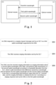
- Fig. 7 is an optical path structure diagram of an OLT optical module according to an embodiment of the present invention.
- the optical module includes an optical transmission assembly TOSA for normal service and data communication control, an optical receiving assembly 1 (ROSA1) for the second uplink wavelength, and an optical receiving assembly 2 (ROSA2) for receiving the first uplink wavelength of the ONU.
- ROSA1 and ROSA2 may be realized using photoelectric detection devices such as an Avalanche Photo Diode (APD) and a Positive-Intrinsic-Negative (PIN).
- APD Avalanche Photo Diode
- PIN Positive-Intrinsic-Negative
- ROSA1 used for normal service communication receives a service sub-wavelength band wavelength emitted by the ONU via a transmission end of the filter 1
- ROSA2 used for ONU registration receives a registration sub-wavelength band wavelength emitted by the ONU via a reflection end of the filter 1.
- the filter 1 of the OLT optical module satisfies the following conditions: the filter 1 has a low-loss transmission for the second uplink wavelength and a low-loss reflection for the first uplink wavelength, and a transmission spectrum and a reflection spectrum thereof need to satisfy the condition of minimal crosstalk in the service sub-wavelength band and the registration sub-wavelength band.
- the OLT optical module further includes a filter 2 for wave combination and separation of TOSA, ROSA1 and ROSA2, so as to realize optical path single-fiber output of the optical module.
- the filter 2 realizes low-loss wave combination and separation of the second uplink wavelength and first uplink wavelength received by the OLT and a working wavelength optical signal emitted thereby.
- sub-band division is only an embodiment of the present invention, and that the sub-band division range may actually be adjusted based on transmitter cost, filter isolation band size, and available wavelength resources.
- an uplink band is re-divided into sub-bands, and the ONU transmitting end requires two wavelength transmitters, or a tunable transmitter is added for tuning, which increases the cost of an ONU-side optical module to a certain extent.
- the first uplink wavelength and the second uplink wavelength in the present solution are divided according to polarization states, and the wavelength ranges are the same, respectively corresponding to a registration sub-wavelength and a service sub-wavelength. For example, ONU transmitting end TE polarized light sends normal service communication information as the second uplink wavelength, and TM polarized light sends registration information as the first uplink wavelength.
- a TE polarized light signal is a received normal communication signal
- a TM polarized light signal is a received registration signal.
- the OLT receiving may adopt direct detection polarization demultiplexing receiving or coherent detection demultiplexing receiving, and the polarization demultiplexing receiving can be realized by a polarization diversity PD detection and a digital signal processing algorithm according to system bandwidth and optical power budget requirements, which will not be described in detail.
- an optical path implementation of an optical transmission assembly of an ONU-side optical module includes a TE polarization state laser, a controllable polarization rotator, and a coupling optical path, etc.
- the TE polarization state laser may be a DML, an EML, a DBR laser, etc. which may load normal service data, and output TE polarized light to a controllable polarization rotator.
- the controllable polarization rotator controls the polarization state of output light to be a TE or TM polarization state according to different stages of the ONU registration process. This is a preferred embodiment for realizing polarization state wavelength division.
- the ONU may also realize the output of double-polarized light through 45-degree linear polarization and polarization beam splitting and combining: polarization loading of normal service data, and loading of registration interaction information.
- Fig. 8 is a schematic diagram of dividing a first uplink wavelength and a second uplink wavelength according to an embodiment of the present invention. As shown in Fig.
- the second uplink wavelength band works at 1531-1534 nm and the first uplink wavelength band works at 1539-1542 nm.
- Each sub-band includes 4 wavelengths spaced apart about 100 GHz, and 4 wavelength grid points of the second uplink wavelength band are 1531.899 nm, 1532.679 nm, 1533.460 nm and 1534.257 nm.
- the 4 wavelength grid points of the first uplink wavelength band are 1539.755 nm, 1540.568 nm, 1541.137 nm and 1542.137 nm, respectively corresponding to the 4 wavelengths of the second uplink wavelength band.
- CH1 in the service sub-wavelength band and CH1 in the registration sub-wavelength band are output from the same port of AWG, ..., CH4 in the service sub-wavelength band and CH4 in the registration sub-wavelength band are output from the same port of AWG.
- the periodic AWG is used for the OLT side to perform wave combination and separation on 4 paths of signals of the TWDM-PON system to a single main fiber.
- Downlink wavelengths may also be based on the periodicity of the device, and the service sub-wavelength, the registration sub-wavelength and the downlink wavelengths are multiplexed and demultiplexed from the same port of AWG.
- the periodic AWG is used as an OLT side combiner-separator device, which is merely one of the embodiments.
- the combiner-separator may also be realized by using a Thin Film Filter (TFF).
- TTF Thin Film Filter
- the ONU optical module further includes a filter 1 for wave combination and separation of TOSA and ROSA, so as to realize optical path single-fiber output of the optical module. If the service sub-wavelength and the registration sub-wavelength at the transmitting end of this module are still located in the TWDM-PON wavelength plan defined by G.989.2, the filter 1 may reuse the original combiner-separator device without redesign.
- the OLT optical device is connected to OLT optical modules CH1-CH4 and a main fiber using a periodic AWG device.
- Downlink wavelengths CH1-CH4 emitted by the OLT optical modules CH1-CH4 are multiplexed to the main fiber.
- Uplink registration sub-wavelengths CH1-CH4 or uplink service sub-wavelengths CH1-CH4 input by the main fiber are respectively demultiplexed to the corresponding OLT optical module for receiving.
- the OLT optical module includes an optical transmission assembly TOSA for normal communication, an optical receiving assembly 1 (ROSA1) for normal communication, and an optical receiving assembly 2 (ROSA2) for receiving a registration wavelength of the ONU.
- ROSA1 and ROSA2 may be implemented using devices such as an APD and a PIN.
- ROSA1 only receives a service sub-wavelength
- ROSA2 only receives a registration sub-wavelength.
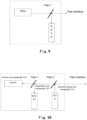
- Fig. 10 is an optical path structure diagram of another OLT optical module according to an embodiment of the present invention.
- ROSA1 used for normal communication receives a service sub-wavelength band wavelength emitted by the ONU via a transmission end of the filter 1
- ROSA2 used for ONU registration receives a registration sub-wavelength band wavelength emitted by the ONU via a reflection end of the filter 1.
- the filter 1 of the OLT optical module satisfies the following conditions.
- the filter 1 has a low-loss transmission for the service sub-wavelength and a low-loss reflection for the registration sub-wavelength, and a transmission spectrum and a reflection spectrum thereof need to satisfy the condition of minimal crosstalk in the service sub-wavelength band and the registration sub-wavelength band.
- the OLT optical module further includes a control module which opens or closes ROSA2 at different stages of the registration process according to control instructions sent by the OLT device.
- the OLT optical module further includes modules such as a controller, a driver, a TIA, etc. a general electrical processing chip and a communication interface, so as to realize the normal working of the optical module and information interaction between the optical module and a device.
- an embodiment of the present invention also provides a storage medium.
- the storage medium stores a computer program.
- the computer program is configured to perform, when executed, the steps in any one of the above method embodiments.
- the above storage medium may be configured to store the computer program for performing the following steps.
- an ONU responds to a ranging request message sent by an OLT on a first uplink wavelength supported by the ONU.
- the ONU receives ranging information sent by the OLT.
- the ONU uses the received ranging information as ranging information about a second uplink wavelength of the ONU, and performs data transmission on the second uplink wavelength according to a bandwidth allocation from the OLT.
- a path transmission time difference caused by a wavelength interval between the first uplink wavelength and the second uplink wavelength is less than a corresponding fault tolerance range when the OLT receives data.
- the ranging information is obtained by the OLT according to a ranging response sent by the ONU on the first uplink wavelength.
- an OLT sends a ranging request message to an ONU on a downlink wavelength, and receives a ranging response message on a first uplink wavelength supported by the ONU.
- the OLT completes ranging of the downlink wavelength and the first uplink wavelength according to the ranging response message, and sends ranging information to the ONU on the downlink wavelength.
- the ranging information is used for instructing the ONU to switch a sending wavelength to a second uplink wavelength supported by the ONU.
- the OLT performs data transmission with the ONU on the second uplink wavelength.
- a path transmission time difference caused by a wavelength interval between the first uplink wavelength and the second uplink wavelength is less than a corresponding fault tolerance range when the OLT receives data.
- the storage medium may include, but is not limited to, various media capable of storing a computer program such as a U disk, a ROM, a RAM, a mobile hard disk, a magnetic disk or an optical disc.
- An embodiment of the present invention also provides an electronic device, which includes a memory and a processor.
- the memory stores a computer program.
- the processor is configured to run the computer program to perform the steps in any one of the above method embodiments.
- the electronic device may further include a transmission device and an input/output device.
- the transmission device is connected to the above processor, and the input/output device is connected to the above processor.
- the above processor may be configured to perform the following steps through a computer program.
- an ONU responds to a ranging request message sent by an OLT on a first uplink wavelength supported by the ONU.
- the ONU receives ranging information sent by the OLT.
- the ONU uses the received ranging information as ranging information about a second uplink wavelength of the ONU, and performs data transmission on the second uplink wavelength according to a bandwidth allocation from the OLT.
- a path transmission time difference caused by a wavelength interval between the first uplink wavelength and the second uplink wavelength is less than a corresponding fault tolerance range when the OLT receives data.
- the ranging information is obtained by the OLT according to a ranging response sent by the ONU on the first uplink wavelength.
- an OLT sends a ranging request message to an ONU on a downlink wavelength, and receives a ranging response message on a first uplink wavelength supported by the ONU.
- the OLT completes ranging of the downlink wavelength and the first uplink wavelength according to the ranging response message, and sends ranging information to the ONU on the downlink wavelength.
- the ranging information is used for instructing the ONU to switch a sending wavelength to a second uplink wavelength supported by the ONU.
- the OLT performs data transmission with the ONU on the second uplink wavelength.
- a path transmission time difference caused by a wavelength interval between the first uplink wavelength and the second uplink wavelength is less than a corresponding fault tolerance range when the OLT receives data.
- a new wavelength capable of maintaining the low delay capacity of an original system is switched. Therefore, it is possible to solve the problem of difficulty in reducing the transmission delay of a service PON system with a high delay requirement in the related art, and the effect of expanding the transmission delay requirement of the service PON system is achieved.
- modules or steps of the present invention may be implemented by a general-purpose computing device, and they may be centralized on a single computing device or distributed on a network composed of multiple computing devices.
- they may be implemented with program codes executable by a computing device, so that they may be stored in a storage device and executed by the computing device, and in some cases, the steps shown or described may be performed in a different order than here, or they are separately made into individual integrated circuit modules, or multiple modules or steps therein are made into a single integrated circuit module for implementation.
- the present invention is not limited to any particular combination of hardware and software.
Landscapes
- Engineering & Computer Science (AREA)
- Computer Networks & Wireless Communication (AREA)
- Signal Processing (AREA)
- Optical Communication System (AREA)
Claims (14)
- Wellenlängenumschaltverfahren für ein passives optisches Netz, PON, umfassend:Antworten (S202), durch eine optische Netzeinheit, ONU, auf eine Entfernungsmessungsanforderungsnachricht, die durch ein optisches Leitungsterminal, OLT, gesendet wird, auf einer ersten Uplink-Wellenlänge, die durch die ONU unterstützt wird;Empfangen (S204), durch die ONU, von Entfernungsmessungsinformationen, die durch das OLT gesendet werden; undVerwenden (S206), durch die ONU, der empfangenen Entfernungsmessungsinformationen als Entfernungsmessungsinformationen über eine zweite Uplink-Wellenlänge der ONU und Durchführen einer Datenübertragung auf der zweiten Uplink-Wellenlänge gemäß einer Bandbreitenzuweisung von dem OLT,wobei die erste Uplink-Wellenlänge und die zweite Uplink-Wellenlänge durch Aufteilen eines Uplink-Bandes in zwei Teilbänder ausgebildet werden, und ein Pfadübertragungszeitunterschied, der durch ein Wellenlängenintervall zwischen der ersten Uplink-Wellenlänge und der zweiten Uplink-Wellenlänge verursacht wird, kleiner als ein entsprechender Fehlertoleranzbereich ist, wenn das OLT Daten empfängt; oder die erste Uplink-Wellenlänge und die zweite Uplink-Wellenlänge entsprechend unterschiedlicher Polarisationszustände aufgeteilt sind, und die Wellenlängenbereiche der ersten Uplink-Wellenlänge und der zweiten Uplink-Wellenlänge gleich sind;wobei die Entfernungsmessungsinformationen, die durch das OLT gemäß einer Entfernungsmessungsantwort erhalten werden, die durch die ONU auf der ersten Uplink-Wellenlänge gesendet wird.
- Verfahren nach Anspruch 1, wobei das Umschalten, durch die ONU, einer Sendewellenlänge auf die zweite Uplink-Wellenlänge, die durch die ONU unterstützt wird, gemäß den Entfernungsmessungsinformationen umfasst:
Abstimmen oder Umschalten, durch die ONU, der Sendewellenlänge von der ersten Uplink-Wellenlänge auf die zweite Uplink-Wellenlänge. - Verfahren nach Anspruch 2, wobei, nachdem die ONU eine Bandbreitenzuweisung von dem OLT empfängt, das Verfahren ferner umfasst:
wenn die ONU selbst bestimmt, Energie zu sparen, oder Wiederherstellungsentfernungsmessungsinformationen empfängt, die durch das OLT gesendet werden, Abstimmen oder Umschalten, durch die ONU, einer aktuellen Sendewellenlänge von der zweiten Uplink-Wellenlänge auf die erste Uplink-Wellenlänge, wobei die Wiederherstellungsentfernungsmessungsinformationen zum Anweisen der ONU, die Sendewellenlänge als die erste Uplink-Wellenlänge zu konfigurieren, verwendet werden. - Verfahren nach einem der Ansprüche 1 bis 3, wobei die Entfernungsmessungsinformationen mindestens eines der Folgenden umfassen: einer äquivalenten Verzögerung oder einer Differenz zwischen einer äquivalenten Verzögerung und einer Leitungsübertragungsverzögerung.
- Verfahren nach einem der Ansprüche 1 bis 3, wobei die zweite Uplink-Wellenlänge zum Übermitteln eines Dienstes verwendet wird, der eine Verzögerung aufweist, die kleiner als ein voreingestellter Verzögerungsschwellenwert ist.
- Verfahren nach einem der Ansprüche 1 bis 3, wobei der Fehlertoleranzbereich mit einer Uplink-Übertragungsrate zwischen der ONU und dem OLT zusammenhängt.
- Verfahren einer Wellenlängenkonfiguration für ein passives optisches Netz, PON, umfassend:Senden (S302), durch ein optisches Leitungsterminal, OLT, einer Entfernungsmessungsanforderungsnachricht an eine optische Netzeinheit, ONU, auf einer Downlink-Wellenlänge und Empfangen einer Entfernungsmessungsantwortnachricht auf einer ersten Uplink-Wellenlänge, die durch die ONU unterstützt wird;Abschließen (S304), durch das OLT, einer Entfernungsmessung der Downlink-Wellenlänge und der ersten Uplink-Wellenlänge gemäß der Entfernungsmessungsantwortnachricht und Senden von Entfernungsmessungsinformationen an die ONU auf der Downlink-Wellenlänge, wobei die Entfernungsmessungsinformationen zum Anweisen der ONU, eine Sendewellenlänge auf eine zweite Uplink-Wellenlänge umzuschalten, die durch die ONU unterstützt wird, verwendet werden; undDurchführen (S306), durch das OLT, einer Datenübertragung mit der ONU auf der zweiten Uplink-Wellenlänge,wobei die erste Uplink-Wellenlänge und die zweite Uplink-Wellenlänge durch Aufteilen eines Uplink-Bandes in zwei Teilbänder ausgebildet werden, und ein Pfadübertragungszeitunterschied, der durch ein Wellenlängenintervall zwischen der ersten Uplink-Wellenlänge und der zweiten Uplink-Wellenlänge verursacht wird, kleiner als ein entsprechender Fehlertoleranzbereich ist, wenn das OLT Daten empfängt; oder die erste Uplink-Wellenlänge und die zweite Uplink-Wellenlänge entsprechend unterschiedlicher Polarisationszustände unterteilt sind und die Wellenlängenbereiche der ersten Uplink-Wellenlänge und der zweiten Uplink-Wellenlänge gleich sind.
- Verfahren nach Anspruch 7, wobei die Entfernungsmessungsinformationen mindestens eines der Folgenden umfassen:
einer äquivalenten Verzögerung oder einer Differenz zwischen einer äquivalenten Verzögerung und einer Leitungsübertragungsverzögerung. - Verfahren nach Anspruch 7, wobei die zweite Uplink-Wellenlänge zum Übermitteln eines Dienstes verwendet wird, der eine Verzögerung aufweist, die kleiner als ein voreingestellter Verzögerungsschwellenwert ist.
- Verfahren nach Anspruch 7, wobei der Fehlertoleranzbereich mit einer Uplink-Übertragungsrate zwischen der ONU und dem OLT zusammenhängt.
- Wellenlängenumschaltvorrichtung für ein passives optisches Netz, PON, das sich auf einer optischen Netzeinheit, ONU, befindet und umfassend:ein Antwortmodul (42), das konfiguriert ist, um auf eine Entfernungsmessungsanforderungsnachricht zu antworten, die durch ein optisches Leitungsterminal, OLT, auf einer ersten Uplink-Wellenlänge gesendet wird, die durch die ONU unterstützt wird;ein Empfangsmodul (44), das konfiguriert ist, um
Entfernungsmessungsinformationen zu empfangen, die durch das OLT gesendet werden; undein Schaltmodul (46), das konfiguriert ist, um die empfangenen Entfernungsmessungsinformationen als Entfernungsmessungsinformationen über eine zweite Uplink-Wellenlänge der ONU zu verwenden und eine Datenübertragung auf der zweiten Uplink-Wellenlänge gemäß einer Bandbreitenzuweisung von dem OLT durchzuführen,wobei die erste Uplink-Wellenlänge und die zweite Uplink-Wellenlänge durch Aufteilen eines Uplink-Bandes in zwei Teilbänder ausgebildet werden, und ein Pfadübertragungszeitunterschied, der durch ein Wellenlängenintervall zwischen der ersten Uplink-Wellenlänge und der zweiten Uplink-Wellenlänge verursacht wird, kleiner als ein entsprechender Fehlertoleranzbereich ist, wenn das OLT Daten empfängt; oder die erste Uplink-Wellenlänge und die zweite Uplink-Wellenlänge entsprechend unterschiedlicher Polarisationszustände unterteilt sind und die Wellenlängenbereiche der ersten Uplink-Wellenlänge und der zweiten Uplink-Wellenlänge gleich sind.wobei die Entfernungsmessungsinformationen, die durch das OLT gemäß einer Entfernungsmessungsantwort erhalten werden, die durch die ONU auf der ersten Uplink-Wellenlänge gesendet wird. - Wellenlängenkonfigurationsvorrichtung für ein passives optisches Netz, PON, das sich in einem optischen Leitungsterminal, OLT, befindet und umfassend:ein Interaktionsmodul (52), das konfiguriert ist, um eine Entfernungsmessungsanforderungsnachricht an eine optische Netzeinheit, ONU, auf einer Downlink-Wellenlänge zu senden und eine
Entfernungsmessungsantwortnachricht auf einer ersten Uplink-Wellenlänge zu empfangen, die durch die ONU unterstützt wird;ein Konfigurationsmodul (54), das konfiguriert ist, um die Entfernungsmessung der Downlink-Wellenlänge und der ersten Uplink-Wellenlänge entsprechend der Entfernungsmessungsantwortnachricht abzuschließen und Entfernungsmessungsinformationen auf der Downlink-Wellenlänge an die ONU zu senden, wobei die Entfernungsmessungsinformationen zum Anweisen der ONU, eine Sendewellenlänge auf eine zweite Uplink-Wellenlänge umzuschalten, die durch die ONU unterstützt wird, verwendet werden; undein Datenübertragungsmodul (56), das konfiguriert ist, um die Datenübertragung mit dem OLT auf der zweiten Uplink-Wellenlänge durchzuführen,wobei die erste Uplink-Wellenlänge und die zweite Uplink-Wellenlänge durch Aufteilen eines Uplink-Bandes in zwei Teilbänder ausgebildet werden, und ein Pfadübertragungszeitunterschied, der durch ein Wellenlängenintervall zwischen der ersten Uplink-Wellenlänge und der zweiten Uplink-Wellenlänge verursacht wird, kleiner als ein entsprechender Fehlertoleranzbereich ist, wenn das OLT Daten empfängt; oder die erste Uplink-Wellenlänge und die zweite Uplink-Wellenlänge entsprechend unterschiedlicher Polarisationszustände unterteilt sind und die Wellenlängenbereiche der ersten Uplink-Wellenlänge und der zweiten Uplink-Wellenlänge gleich sind. - Speicherungsmedium, das ein Computerprogramm darauf speichert, wobei das Computerprogramm konfiguriert ist, um, wenn es ausgeführt wird, das Verfahren nach einem der Ansprüche 1 bis 10 durchzuführen.
- Elektronische Vorrichtung, umfassend einen Speicher und einen Prozessor, wobei der Speicher ein Computerprogramm speichert und der Prozessor konfiguriert ist, um das Computerprogramm auszuführen, um das Verfahren nach einem der Ansprüche 1 bis 10 durchzuführen.
Applications Claiming Priority (2)
| Application Number | Priority Date | Filing Date | Title |
|---|---|---|---|
| CN201910523626.3A CN112104927B (zh) | 2019-06-17 | 2019-06-17 | 一种无源光网络的波长切换、配置方法及装置 |
| PCT/CN2020/094261 WO2020253540A1 (zh) | 2019-06-17 | 2020-06-04 | 无源光网络的波长切换、配置方法及装置 |
Publications (3)
| Publication Number | Publication Date |
|---|---|
| EP3985992A1 EP3985992A1 (de) | 2022-04-20 |
| EP3985992A4 EP3985992A4 (de) | 2022-08-03 |
| EP3985992B1 true EP3985992B1 (de) | 2024-10-23 |
Family
ID=73748562
Family Applications (1)
| Application Number | Title | Priority Date | Filing Date |
|---|---|---|---|
| EP20826461.4A Active EP3985992B1 (de) | 2019-06-17 | 2020-06-04 | Verfahren und vorrichtungen zur wellenlängenumschaltung und -konfiguration für passives optisches netzwerk |
Country Status (5)
| Country | Link |
|---|---|
| US (1) | US12028153B2 (de) |
| EP (1) | EP3985992B1 (de) |
| CN (1) | CN112104927B (de) |
| ES (1) | ES3005838T3 (de) |
| WO (1) | WO2020253540A1 (de) |
Families Citing this family (5)
| Publication number | Priority date | Publication date | Assignee | Title |
|---|---|---|---|---|
| CN114666683A (zh) * | 2020-12-23 | 2022-06-24 | 中国移动通信有限公司研究院 | 光网络单元上线注册方法、光网络单元和光线路终端 |
| CN114666684B (zh) * | 2020-12-23 | 2025-09-19 | 中国移动通信有限公司研究院 | 光网络单元上线注册方法、光网络单元和光线路终端 |
| CN114727174B (zh) * | 2021-01-05 | 2025-09-05 | 中国移动通信有限公司研究院 | 一种光网络单元注册上线方法、设备及存储介质 |
| CN116546354B (zh) * | 2023-05-31 | 2026-03-31 | 烽火通信科技股份有限公司 | 一种olt设备、onu设备及故障onu远程管控的方法 |
| CN121218055A (zh) * | 2024-06-25 | 2025-12-26 | 中兴通讯股份有限公司 | 无源光网络的信号处理方法、光线路终端及光网络单元 |
Family Cites Families (15)
| Publication number | Priority date | Publication date | Assignee | Title |
|---|---|---|---|---|
| KR100490901B1 (ko) * | 2002-12-02 | 2005-05-24 | 한국전자통신연구원 | 이더넷 수동 광통신망에서 서비스 등급별 동적대역 할당방법 및 대역할당장치 |
| US8208815B1 (en) * | 2006-11-30 | 2012-06-26 | Marvell International Ltd. | Bit accurate upstream burst transmission phase method for reducing burst data arrival variation |
| JP4820791B2 (ja) * | 2007-09-21 | 2011-11-24 | 株式会社日立製作所 | パッシブ光ネットワークシステムおよびレンジング方法 |
| US8649681B2 (en) * | 2008-12-01 | 2014-02-11 | Telefonaktiebolaget Lm Ericsson (Publ) | Methods and devices for wavelength alignment in WDM-PON |
| US9712241B2 (en) * | 2012-04-20 | 2017-07-18 | Mitsubishi Electric Corporation | Communication system, master station device, slave station device, control unit, and communication control method |
| CN103636153B (zh) | 2012-06-13 | 2016-09-14 | 华为技术有限公司 | 多波长无源光网络的波长配置方法、系统和装置 |
| CN103841474B (zh) | 2012-11-23 | 2019-01-25 | 中兴通讯股份有限公司 | 一种无源光网络中的波长调谐方法、系统及设备 |
| CN103840903A (zh) | 2012-11-23 | 2014-06-04 | 中兴通讯股份有限公司 | 工作波长的调谐方法及系统 |
| CN107294637B (zh) | 2013-02-06 | 2019-06-04 | 上海诺基亚贝尔股份有限公司 | 一种用于自动配置光网络单元的波长的方法 |
| US9577783B2 (en) * | 2014-01-23 | 2017-02-21 | Futurewei Technologies, Inc. | Optical line terminal communication method and device with data structure |
| CN107395315A (zh) * | 2016-05-16 | 2017-11-24 | 中兴通讯股份有限公司 | 一种无源光网络中的测距方法、光线路终端和光网络单元 |
| ES2906748T3 (es) | 2016-11-23 | 2022-04-20 | Huawei Tech Co Ltd | Sistema de red óptica pasiva, terminal de línea óptica y unidad de red óptica |
| EP3382919A4 (de) * | 2017-01-24 | 2019-01-16 | Huawei Technologies Co., Ltd. | Kommunikationsverfahren, vorrichtung und system für ein passives optisches netzwerk (pon) |
| CN111344968B (zh) * | 2017-09-05 | 2023-03-07 | 丹麦科技大学 | 光线路终端和容量增加的光纤接入系统 |
| CN109495797B (zh) * | 2017-09-13 | 2022-02-22 | 中兴通讯股份有限公司 | 一种无源光网络中onu的管理方法、olt和系统 |
-
2019
- 2019-06-17 CN CN201910523626.3A patent/CN112104927B/zh active Active
-
2020
- 2020-06-04 EP EP20826461.4A patent/EP3985992B1/de active Active
- 2020-06-04 US US17/620,216 patent/US12028153B2/en active Active
- 2020-06-04 ES ES20826461T patent/ES3005838T3/es active Active
- 2020-06-04 WO PCT/CN2020/094261 patent/WO2020253540A1/zh not_active Ceased
Also Published As
| Publication number | Publication date |
|---|---|
| US20220271858A1 (en) | 2022-08-25 |
| ES3005838T3 (en) | 2025-03-17 |
| EP3985992A4 (de) | 2022-08-03 |
| US12028153B2 (en) | 2024-07-02 |
| EP3985992A1 (de) | 2022-04-20 |
| CN112104927A (zh) | 2020-12-18 |
| CN112104927B (zh) | 2023-11-17 |
| WO2020253540A1 (zh) | 2020-12-24 |
Similar Documents
| Publication | Publication Date | Title |
|---|---|---|
| EP3985992B1 (de) | Verfahren und vorrichtungen zur wellenlängenumschaltung und -konfiguration für passives optisches netzwerk | |
| US20140233954A1 (en) | Link establishment method for multi-wavelength passive optical network system | |
| Cheng et al. | Flexible TWDM PON system with pluggable optical transceiver modules | |
| US9112600B2 (en) | Wavelength tuning time measurement apparatus and method for multi-wavelength passive optical network | |
| US20160352428A1 (en) | Flexible TWDM PON with Load Balancing and Power Saving | |
| Cheng et al. | Flexible TWDM PON with load balancing and power saving | |
| Cheng | Flexible TWDM PON with WDM overlay for converged services | |
| EP3672122B1 (de) | Kalibrierungsvorrichtung und -verfahren und wellenlängenmultiplexsystem | |
| JP5457557B2 (ja) | 波長分割多重アクセスネットワークを動作させるための装置および方法 | |
| US20230208522A1 (en) | Communication system and method, and related device | |
| Honda et al. | Wavelength adjustment of upstream signal using AMCC with power monitoring for WDM-PON in 5G mobile era | |
| CN101536537B (zh) | 管理光接入网中的连接的方法以及相关的平台、交换局、网络和计算机软件产品 | |
| Li et al. | POPSMAC: A medium access protocol for packet-switched passive optical networks using WDMA | |
| US9831946B2 (en) | Optical transmitter and transmission method, and optical receiver and receiption method | |
| Suzuki et al. | A transponder aggregator with efficient use of filtering function for transponder noise suppression | |
| Kodama et al. | Bypass/backup-link switchable coherent point-to-multipoint configured WDM-PON system with shared protection | |
| US10805033B2 (en) | Optical line terminal, and signal transmission method and device | |
| WO2012106920A1 (zh) | 光模块及其突发发射方法、激光器及光网络系统 | |
| Tien et al. | A novel OFDMA-PON architecture toward seamless broadband and wireless integration | |
| Róka | The utilization of the DWDM/CWDM combination in the metro/access networks | |
| Lee | ONU Interconnection for Reducing Latency in TWDM-PON Based Mobile Front-and Middle-Hauls by using Wavelength Mobility | |
| KR20130007481A (ko) | 파장분할다중화방식 수동형 광통신 네트워크 시스템을 위한 링크 설정 방법 | |
| Townsend et al. | Towards colourless coolerless components for low power optical networks | |
| Mekonnen | Dynamic ultrahigh-capacity indoor wireless communication using optical-wireless and millimeter-wave radio techniques | |
| Liu et al. | A novel wavelength sharing TWDM-PON architecture with tunable laser and multi-free-spectral-range AWGR |
Legal Events
| Date | Code | Title | Description |
|---|---|---|---|
| STAA | Information on the status of an ep patent application or granted ep patent |
Free format text: STATUS: THE INTERNATIONAL PUBLICATION HAS BEEN MADE |
|
| PUAI | Public reference made under article 153(3) epc to a published international application that has entered the european phase |
Free format text: ORIGINAL CODE: 0009012 |
|
| STAA | Information on the status of an ep patent application or granted ep patent |
Free format text: STATUS: REQUEST FOR EXAMINATION WAS MADE |
|
| 17P | Request for examination filed |
Effective date: 20211227 |
|
| AK | Designated contracting states |
Kind code of ref document: A1 Designated state(s): AL AT BE BG CH CY CZ DE DK EE ES FI FR GB GR HR HU IE IS IT LI LT LU LV MC MK MT NL NO PL PT RO RS SE SI SK SM TR |
|
| A4 | Supplementary search report drawn up and despatched |
Effective date: 20220701 |
|
| RIC1 | Information provided on ipc code assigned before grant |
Ipc: H04J 14/02 20060101ALI20220627BHEP Ipc: H04Q 11/00 20060101AFI20220627BHEP |
|
| DAV | Request for validation of the european patent (deleted) | ||
| DAX | Request for extension of the european patent (deleted) | ||
| GRAP | Despatch of communication of intention to grant a patent |
Free format text: ORIGINAL CODE: EPIDOSNIGR1 |
|
| STAA | Information on the status of an ep patent application or granted ep patent |
Free format text: STATUS: GRANT OF PATENT IS INTENDED |
|
| INTG | Intention to grant announced |
Effective date: 20240524 |
|
| GRAS | Grant fee paid |
Free format text: ORIGINAL CODE: EPIDOSNIGR3 |
|
| GRAA | (expected) grant |
Free format text: ORIGINAL CODE: 0009210 |
|
| STAA | Information on the status of an ep patent application or granted ep patent |
Free format text: STATUS: THE PATENT HAS BEEN GRANTED |
|
| AK | Designated contracting states |
Kind code of ref document: B1 Designated state(s): AL AT BE BG CH CY CZ DE DK EE ES FI FR GB GR HR HU IE IS IT LI LT LU LV MC MK MT NL NO PL PT RO RS SE SI SK SM TR |
|
| REG | Reference to a national code |
Ref country code: GB Ref legal event code: FG4D |
|
| REG | Reference to a national code |
Ref country code: CH Ref legal event code: EP |
|
| REG | Reference to a national code |
Ref country code: DE Ref legal event code: R096 Ref document number: 602020040012 Country of ref document: DE |
|
| REG | Reference to a national code |
Ref country code: IE Ref legal event code: FG4D |
|
| REG | Reference to a national code |
Ref country code: LT Ref legal event code: MG9D |
|
| REG | Reference to a national code |
Ref country code: NL Ref legal event code: MP Effective date: 20241023 |
|
| REG | Reference to a national code |
Ref country code: AT Ref legal event code: MK05 Ref document number: 1735824 Country of ref document: AT Kind code of ref document: T Effective date: 20241023 |
|
| PG25 | Lapsed in a contracting state [announced via postgrant information from national office to epo] |
Ref country code: NL Free format text: LAPSE BECAUSE OF FAILURE TO SUBMIT A TRANSLATION OF THE DESCRIPTION OR TO PAY THE FEE WITHIN THE PRESCRIBED TIME-LIMIT Effective date: 20241023 |
|
| REG | Reference to a national code |
Ref country code: ES Ref legal event code: FG2A Ref document number: 3005838 Country of ref document: ES Kind code of ref document: T3 Effective date: 20250317 |
|
| PG25 | Lapsed in a contracting state [announced via postgrant information from national office to epo] |
Ref country code: NL Free format text: LAPSE BECAUSE OF FAILURE TO SUBMIT A TRANSLATION OF THE DESCRIPTION OR TO PAY THE FEE WITHIN THE PRESCRIBED TIME-LIMIT Effective date: 20241023 |
|
| PG25 | Lapsed in a contracting state [announced via postgrant information from national office to epo] |
Ref country code: IS Free format text: LAPSE BECAUSE OF FAILURE TO SUBMIT A TRANSLATION OF THE DESCRIPTION OR TO PAY THE FEE WITHIN THE PRESCRIBED TIME-LIMIT Effective date: 20250223 Ref country code: PT Free format text: LAPSE BECAUSE OF FAILURE TO SUBMIT A TRANSLATION OF THE DESCRIPTION OR TO PAY THE FEE WITHIN THE PRESCRIBED TIME-LIMIT Effective date: 20250224 Ref country code: HR Free format text: LAPSE BECAUSE OF FAILURE TO SUBMIT A TRANSLATION OF THE DESCRIPTION OR TO PAY THE FEE WITHIN THE PRESCRIBED TIME-LIMIT Effective date: 20241023 |
|
| PG25 | Lapsed in a contracting state [announced via postgrant information from national office to epo] |
Ref country code: FI Free format text: LAPSE BECAUSE OF FAILURE TO SUBMIT A TRANSLATION OF THE DESCRIPTION OR TO PAY THE FEE WITHIN THE PRESCRIBED TIME-LIMIT Effective date: 20241023 |
|
| PG25 | Lapsed in a contracting state [announced via postgrant information from national office to epo] |
Ref country code: BG Free format text: LAPSE BECAUSE OF FAILURE TO SUBMIT A TRANSLATION OF THE DESCRIPTION OR TO PAY THE FEE WITHIN THE PRESCRIBED TIME-LIMIT Effective date: 20241023 |
|
| PG25 | Lapsed in a contracting state [announced via postgrant information from national office to epo] |
Ref country code: NO Free format text: LAPSE BECAUSE OF FAILURE TO SUBMIT A TRANSLATION OF THE DESCRIPTION OR TO PAY THE FEE WITHIN THE PRESCRIBED TIME-LIMIT Effective date: 20250123 |
|
| PG25 | Lapsed in a contracting state [announced via postgrant information from national office to epo] |
Ref country code: LV Free format text: LAPSE BECAUSE OF FAILURE TO SUBMIT A TRANSLATION OF THE DESCRIPTION OR TO PAY THE FEE WITHIN THE PRESCRIBED TIME-LIMIT Effective date: 20241023 Ref country code: AT Free format text: LAPSE BECAUSE OF FAILURE TO SUBMIT A TRANSLATION OF THE DESCRIPTION OR TO PAY THE FEE WITHIN THE PRESCRIBED TIME-LIMIT Effective date: 20241023 Ref country code: GR Free format text: LAPSE BECAUSE OF FAILURE TO SUBMIT A TRANSLATION OF THE DESCRIPTION OR TO PAY THE FEE WITHIN THE PRESCRIBED TIME-LIMIT Effective date: 20250124 |
|
| PG25 | Lapsed in a contracting state [announced via postgrant information from national office to epo] |
Ref country code: PL Free format text: LAPSE BECAUSE OF FAILURE TO SUBMIT A TRANSLATION OF THE DESCRIPTION OR TO PAY THE FEE WITHIN THE PRESCRIBED TIME-LIMIT Effective date: 20241023 |
|
| PG25 | Lapsed in a contracting state [announced via postgrant information from national office to epo] |
Ref country code: RS Free format text: LAPSE BECAUSE OF FAILURE TO SUBMIT A TRANSLATION OF THE DESCRIPTION OR TO PAY THE FEE WITHIN THE PRESCRIBED TIME-LIMIT Effective date: 20250123 |
|
| PG25 | Lapsed in a contracting state [announced via postgrant information from national office to epo] |
Ref country code: SM Free format text: LAPSE BECAUSE OF FAILURE TO SUBMIT A TRANSLATION OF THE DESCRIPTION OR TO PAY THE FEE WITHIN THE PRESCRIBED TIME-LIMIT Effective date: 20241023 |
|
| PGFP | Annual fee paid to national office [announced via postgrant information from national office to epo] |
Ref country code: DE Payment date: 20250618 Year of fee payment: 6 |
|
| PG25 | Lapsed in a contracting state [announced via postgrant information from national office to epo] |
Ref country code: DK Free format text: LAPSE BECAUSE OF FAILURE TO SUBMIT A TRANSLATION OF THE DESCRIPTION OR TO PAY THE FEE WITHIN THE PRESCRIBED TIME-LIMIT Effective date: 20241023 |
|
| PGFP | Annual fee paid to national office [announced via postgrant information from national office to epo] |
Ref country code: GB Payment date: 20250618 Year of fee payment: 6 |
|
| PG25 | Lapsed in a contracting state [announced via postgrant information from national office to epo] |
Ref country code: EE Free format text: LAPSE BECAUSE OF FAILURE TO SUBMIT A TRANSLATION OF THE DESCRIPTION OR TO PAY THE FEE WITHIN THE PRESCRIBED TIME-LIMIT Effective date: 20241023 |
|
| PG25 | Lapsed in a contracting state [announced via postgrant information from national office to epo] |
Ref country code: RO Free format text: LAPSE BECAUSE OF FAILURE TO SUBMIT A TRANSLATION OF THE DESCRIPTION OR TO PAY THE FEE WITHIN THE PRESCRIBED TIME-LIMIT Effective date: 20241023 |
|
| REG | Reference to a national code |
Ref country code: DE Ref legal event code: R097 Ref document number: 602020040012 Country of ref document: DE |
|
| PG25 | Lapsed in a contracting state [announced via postgrant information from national office to epo] |
Ref country code: SK Free format text: LAPSE BECAUSE OF FAILURE TO SUBMIT A TRANSLATION OF THE DESCRIPTION OR TO PAY THE FEE WITHIN THE PRESCRIBED TIME-LIMIT Effective date: 20241023 |
|
| PG25 | Lapsed in a contracting state [announced via postgrant information from national office to epo] |
Ref country code: CZ Free format text: LAPSE BECAUSE OF FAILURE TO SUBMIT A TRANSLATION OF THE DESCRIPTION OR TO PAY THE FEE WITHIN THE PRESCRIBED TIME-LIMIT Effective date: 20241023 |
|
| PLBE | No opposition filed within time limit |
Free format text: ORIGINAL CODE: 0009261 |
|
| STAA | Information on the status of an ep patent application or granted ep patent |
Free format text: STATUS: NO OPPOSITION FILED WITHIN TIME LIMIT |
|
| PG25 | Lapsed in a contracting state [announced via postgrant information from national office to epo] |
Ref country code: SE Free format text: LAPSE BECAUSE OF FAILURE TO SUBMIT A TRANSLATION OF THE DESCRIPTION OR TO PAY THE FEE WITHIN THE PRESCRIBED TIME-LIMIT Effective date: 20241023 |
|
| 26N | No opposition filed |
Effective date: 20250724 |
|
| PGFP | Annual fee paid to national office [announced via postgrant information from national office to epo] |
Ref country code: ES Payment date: 20250731 Year of fee payment: 6 |
|
| PGFP | Annual fee paid to national office [announced via postgrant information from national office to epo] |
Ref country code: IT Payment date: 20250624 Year of fee payment: 6 |
|
| REG | Reference to a national code |
Ref country code: CH Ref legal event code: H13 Free format text: ST27 STATUS EVENT CODE: U-0-0-H10-H13 (AS PROVIDED BY THE NATIONAL OFFICE) Effective date: 20260127 |
|
| PG25 | Lapsed in a contracting state [announced via postgrant information from national office to epo] |
Ref country code: MC Free format text: LAPSE BECAUSE OF FAILURE TO SUBMIT A TRANSLATION OF THE DESCRIPTION OR TO PAY THE FEE WITHIN THE PRESCRIBED TIME-LIMIT Effective date: 20241023 |
|
| PG25 | Lapsed in a contracting state [announced via postgrant information from national office to epo] |
Ref country code: LU Free format text: LAPSE BECAUSE OF NON-PAYMENT OF DUE FEES Effective date: 20250604 |
|
| REG | Reference to a national code |
Ref country code: BE Ref legal event code: MM Effective date: 20250630 |
|
| PG25 | Lapsed in a contracting state [announced via postgrant information from national office to epo] |
Ref country code: IE Free format text: LAPSE BECAUSE OF NON-PAYMENT OF DUE FEES Effective date: 20250604 |
|
| PG25 | Lapsed in a contracting state [announced via postgrant information from national office to epo] |
Ref country code: BE Free format text: LAPSE BECAUSE OF NON-PAYMENT OF DUE FEES Effective date: 20250630 |
|
| PG25 | Lapsed in a contracting state [announced via postgrant information from national office to epo] |
Ref country code: FR Free format text: LAPSE BECAUSE OF NON-PAYMENT OF DUE FEES Effective date: 20250630 |
|
| PG25 | Lapsed in a contracting state [announced via postgrant information from national office to epo] |
Ref country code: CH Free format text: LAPSE BECAUSE OF NON-PAYMENT OF DUE FEES Effective date: 20250630 |