EP3986062A1 - Procédé et appareil de transmission de données - Google Patents
Procédé et appareil de transmission de données Download PDFInfo
- Publication number
- EP3986062A1 EP3986062A1 EP21184137.4A EP21184137A EP3986062A1 EP 3986062 A1 EP3986062 A1 EP 3986062A1 EP 21184137 A EP21184137 A EP 21184137A EP 3986062 A1 EP3986062 A1 EP 3986062A1
- Authority
- EP
- European Patent Office
- Prior art keywords
- station
- target
- ofdma ppdu
- uplink
- physical layer
- Prior art date
- Legal status (The legal status is an assumption and is not a legal conclusion. Google has not performed a legal analysis and makes no representation as to the accuracy of the status listed.)
- Granted
Links
Images





Classifications
-
- H—ELECTRICITY
- H04—ELECTRIC COMMUNICATION TECHNIQUE
- H04W—WIRELESS COMMUNICATION NETWORKS
- H04W74/00—Wireless channel access
- H04W74/002—Transmission of channel access control information
-
- H—ELECTRICITY
- H04—ELECTRIC COMMUNICATION TECHNIQUE
- H04W—WIRELESS COMMUNICATION NETWORKS
- H04W72/00—Local resource management
-
- H—ELECTRICITY
- H04—ELECTRIC COMMUNICATION TECHNIQUE
- H04L—TRANSMISSION OF DIGITAL INFORMATION, e.g. TELEGRAPHIC COMMUNICATION
- H04L5/00—Arrangements affording multiple use of the transmission path
- H04L5/003—Arrangements for allocating sub-channels of the transmission path
- H04L5/0053—Allocation of signalling, i.e. of overhead other than pilot signals
-
- H—ELECTRICITY
- H04—ELECTRIC COMMUNICATION TECHNIQUE
- H04L—TRANSMISSION OF DIGITAL INFORMATION, e.g. TELEGRAPHIC COMMUNICATION
- H04L5/00—Arrangements affording multiple use of the transmission path
- H04L5/003—Arrangements for allocating sub-channels of the transmission path
- H04L5/0048—Allocation of pilot signals, i.e. of signals known to the receiver
-
- H—ELECTRICITY
- H04—ELECTRIC COMMUNICATION TECHNIQUE
- H04L—TRANSMISSION OF DIGITAL INFORMATION, e.g. TELEGRAPHIC COMMUNICATION
- H04L1/00—Arrangements for detecting or preventing errors in the information received
- H04L1/12—Arrangements for detecting or preventing errors in the information received by using return channel
- H04L1/16—Arrangements for detecting or preventing errors in the information received by using return channel in which the return channel carries supervisory signals, e.g. repetition request signals
- H04L1/1607—Details of the supervisory signal
- H04L1/1635—Cumulative acknowledgement, i.e. the acknowledgement message applying to all previous messages
-
- H—ELECTRICITY
- H04—ELECTRIC COMMUNICATION TECHNIQUE
- H04L—TRANSMISSION OF DIGITAL INFORMATION, e.g. TELEGRAPHIC COMMUNICATION
- H04L5/00—Arrangements affording multiple use of the transmission path
- H04L5/0001—Arrangements for dividing the transmission path
- H04L5/0003—Two-dimensional division
- H04L5/0005—Time-frequency
- H04L5/0007—Time-frequency the frequencies being orthogonal, e.g. OFDM(A) or DMT
-
- H—ELECTRICITY
- H04—ELECTRIC COMMUNICATION TECHNIQUE
- H04L—TRANSMISSION OF DIGITAL INFORMATION, e.g. TELEGRAPHIC COMMUNICATION
- H04L5/00—Arrangements affording multiple use of the transmission path
- H04L5/003—Arrangements for allocating sub-channels of the transmission path
- H04L5/0044—Allocation of payload; Allocation of data channels, e.g. PDSCH or PUSCH
-
- H—ELECTRICITY
- H04—ELECTRIC COMMUNICATION TECHNIQUE
- H04L—TRANSMISSION OF DIGITAL INFORMATION, e.g. TELEGRAPHIC COMMUNICATION
- H04L5/00—Arrangements affording multiple use of the transmission path
- H04L5/003—Arrangements for allocating sub-channels of the transmission path
- H04L5/0053—Allocation of signalling, i.e. of overhead other than pilot signals
- H04L5/0055—Physical resource allocation for ACK/NACK
-
- H—ELECTRICITY
- H04—ELECTRIC COMMUNICATION TECHNIQUE
- H04L—TRANSMISSION OF DIGITAL INFORMATION, e.g. TELEGRAPHIC COMMUNICATION
- H04L5/00—Arrangements affording multiple use of the transmission path
- H04L5/0091—Signalling for the administration of the divided path, e.g. signalling of configuration information
- H04L5/0094—Indication of how sub-channels of the path are allocated
-
- H—ELECTRICITY
- H04—ELECTRIC COMMUNICATION TECHNIQUE
- H04W—WIRELESS COMMUNICATION NETWORKS
- H04W72/00—Local resource management
- H04W72/04—Wireless resource allocation
-
- H—ELECTRICITY
- H04—ELECTRIC COMMUNICATION TECHNIQUE
- H04W—WIRELESS COMMUNICATION NETWORKS
- H04W72/00—Local resource management
- H04W72/04—Wireless resource allocation
- H04W72/044—Wireless resource allocation based on the type of the allocated resource
- H04W72/0446—Resources in time domain, e.g. slots or frames
-
- H—ELECTRICITY
- H04—ELECTRIC COMMUNICATION TECHNIQUE
- H04W—WIRELESS COMMUNICATION NETWORKS
- H04W72/00—Local resource management
- H04W72/04—Wireless resource allocation
- H04W72/044—Wireless resource allocation based on the type of the allocated resource
- H04W72/0453—Resources in frequency domain, e.g. a carrier in FDMA
-
- H—ELECTRICITY
- H04—ELECTRIC COMMUNICATION TECHNIQUE
- H04W—WIRELESS COMMUNICATION NETWORKS
- H04W74/00—Wireless channel access
-
- H—ELECTRICITY
- H04—ELECTRIC COMMUNICATION TECHNIQUE
- H04W—WIRELESS COMMUNICATION NETWORKS
- H04W74/00—Wireless channel access
- H04W74/08—Non-scheduled access, e.g. ALOHA
- H04W74/0808—Non-scheduled access, e.g. ALOHA using carrier sensing, e.g. carrier sense multiple access [CSMA]
-
- H—ELECTRICITY
- H04—ELECTRIC COMMUNICATION TECHNIQUE
- H04W—WIRELESS COMMUNICATION NETWORKS
- H04W84/00—Network topologies
- H04W84/02—Hierarchically pre-organised networks, e.g. paging networks, cellular networks, WLAN [Wireless Local Area Network] or WLL [Wireless Local Loop]
- H04W84/10—Small scale networks; Flat hierarchical networks
- H04W84/12—WLAN [Wireless Local Area Networks]
-
- H—ELECTRICITY
- H04—ELECTRIC COMMUNICATION TECHNIQUE
- H04W—WIRELESS COMMUNICATION NETWORKS
- H04W88/00—Devices specially adapted for wireless communication networks, e.g. terminals, base stations or access point devices
- H04W88/08—Access point devices
Definitions
- Embodiments of the present invention relate to the field of wireless network technologies, and in particular, to a data transmission method and apparatus.
- WLAN Wireless Local Area Network
- an orthogonal frequency division multiple access (Orthogonal Frequency Division Multiple Access, OFDMA) technology is further used based on an existing orthogonal frequency division multiplexing (OFDM, Orthogonal Frequency Division Multiplexing) technology.
- OFDMA orthogonal frequency division multiple access
- air interface radio channel time-frequency resources are divided into multiple orthogonal time-frequency resource unit (Resource Unit, RU)s.
- the RUs may share time, but are orthogonal in a frequency domain.
- the OFDMA technology supports multiple nodes in simultaneously sending and receiving data.
- An access point (Access Point, AP) allocates different RUs to different STAs at a same moment, so that multiple STAs simultaneously and efficiently access a channel, thereby improving channel utilization.
- AP Access Point
- uplink data transmission is no longer point-to-point transmission, but is multipoint-to-point transmission.
- multiple STAs simultaneously transmit data to an AP at a same time on a same channel by using RUs allocated to the STAs.
- the multiple STAs are overlapped basic service set (Overlap Basic Service Set, OBSS) stations.
- OBSS overlap Basic Service Set
- a common physical layer preamble (legacy-preamble, RL-SIG, and High Efficiency (HE)-SIG-A) needs to be repeatedly sent in each 20 MHz fundamental channel unit in channel bandwidth (BandWidth, BW), and a data part of the station is transmitted in an RU allocated to the station.
- BW channel bandwidth
- a legacy 802.11a/b/n/ac station and 802.11ax station of another BSS perform detection according to a legacy clear channel assessment (Clear Channel Assessment, CCA) method
- CCA Clear Channel Assessment
- a STA sends a common physical layer preamble on each fundamental channel unit, it is detected that multiple 20 MHz channels are occupied even though a data part of the station is transmitted on an RU in only one of the multiple 20 MHz channels. Consequently, in the transmission manner, another BSS station is prevented from contending for a 20 MHz channel without a data part, and this is not advantageous for improving spectrum utilization.
- Embodiments of the present invention provide a data transmission method and apparatus. It is designed that a common physical layer preamble is sent on at least one fundamental channel unit in which a target RU is located to improve spectrum utilization.
- an embodiment of the present invention provides a data transmission method.
- the method is performed by a non-access type station STA in a wireless network, and the STA interacts with an access type station AP.
- the station receives a trigger frame sent by the access point, where the trigger frame includes an identifier of a target frequency domain resource unit RU allocated by the access point to the station.
- the station sends an uplink orthogonal frequency division multiple access physical layer protocol data unit OFDMA PPDU, where a data part of the OFDMA PPDU is sent on the target RU allocated by the access point, and a common physical layer preamble of the OFDMA PPDU is sent on at least one fundamental channel unit in which the target RU is located.
- the station receives an acknowledgement frame fed back for the OFDMA PPDU.
- the fundamental channel unit in which the target RU is located includes at least two fundamental channel units
- the common physical layer preamble of the OFDMA PPDU is repeatedly sent on each of the at least two fundamental channel units.
- the common physical layer preamble includes a legacy preamble legacy preamble field, a repeated legacy signal RL-SIG field, and a high efficiency signaling HE-SIG-A field.
- the station skips sending the common physical layer preamble, or the station sends the common physical layer preamble on one or two fundamental channel units adjacent to the target RU.
- the acknowledgement frame sent by the station to the access point may be sent by the access point on an RU selected by the access point from the at least one fundamental channel unit; or the access point may encapsulate the acknowledgement frame sent by the station to the access point as an encapsulation packet and then send the encapsulation packet on an RU in the at least one fundamental channel unit, where the encapsulation packet includes acknowledgement frames fed back by the access point for multiple stations.
- the access point transmits a preset frame structure on the primary fundamental channel unit.
- an embodiment of the present invention provides a data transmission apparatus, where the apparatus is applied to a station and includes a receiving module and a sending module.
- the receiving module is configured to receive a trigger frame sent by an access point, where the trigger frame includes an identifier of a target frequency domain resource unit RU allocated to the station.
- the sending module is configured to send an uplink orthogonal frequency division multiple access physical layer protocol data unit OFDMA PPDU, where a data part of the OFDMA PPDU is sent on the target RU, and a common physical layer preamble of the OFDMA PPDU is sent on at least one fundamental channel unit in which the target RU is located.
- the receiving module is further configured to receive an acknowledgement frame fed back for the OFDMA PPDU.
- an embodiment of the present invention provides a data transmission apparatus, which is applied to a station.
- the data transmission apparatus includes: a memory, configured to store computer executable program code; a transceiver; and a processor coupled to the memory and the transceiver.
- the program code includes an instruction.
- the instruction When the processor executes the instruction, the instruction enables the data transmission apparatus to perform the following operations: receiving a trigger frame sent by an access point, where the trigger frame includes an identifier of a target frequency domain resource unit RU allocated by the access point to the station; then sending an uplink orthogonal frequency division multiple access physical layer protocol data unit OFDMA PPDU, where a data part of the OFDMA PPDU is sent on the target RU allocated by the access point, and a common physical layer preamble of the OFDMA PPDU is sent on at least one fundamental channel unit in which the target RU is located; and finally receiving an acknowledgement frame fed back for the OFDMA PPDU.
- an embodiment of the present invention provides a computer storage medium, configured to store a computer software instruction used by the foregoing data transmission apparatus, and the computer storage medium includes a program designed for performing the foregoing aspects.
- the station receives the trigger frame sent by the access point.
- the trigger frame includes the identifier of the target RU allocated to the station.
- the station sends the uplink OFDMA PPDU.
- the data part of the OFDMA PPDU is sent on the target RU, and the common physical layer preamble of the OFDMA PPDU is sent on the at least one fundamental channel unit in which the target RU is located.
- the station receives the acknowledgement frame fed back for the OFDMA PPDU.
- a common physical layer preamble of an OFDMA PPDU is sent only on at least one fundamental channel unit in which an allocated target RU is located. Therefore, spectrum resources occupied by the common physical layer preamble are reduced, so that more stations contend for access to a channel, improving spectrum utilization.
- the embodiments of the present invention may be applied to a wireless local area network (Wireless Local Area Network, WLAN).
- WLAN Wireless Local Area Network
- a standard used in the WLAN is IEEE (English: Institute of Electrical and Electronics Engineers, Institute of Electrical and Electronics Engineers) 802.11 series.
- the WLAN may include multiple basic service sets BSSs.
- a network node in the basic service set is a station.
- the station includes an access point type station (Access Point, AP) and a non-access point type station (English: None Access Point Station, Non-AP STA for short).
- Each basic service set may include one AP and multiple non-AP STAs associated with the AP.
- the access point type station is also referred to as a wireless access point, a hotspot, or the like.
- An AP is an access point by using which a mobile user enters a wired network.
- the AP is mainly deployed in home or within a building and a park with a typical coverage radius of tens to hundreds of meters, and certainly may also be deployed outdoors.
- the AP is equivalent to a bridge connecting a wired network and a wireless network.
- a main function of the AP is to connect wireless network clients, and then connect the wireless network to an Ethernet network.
- the AP may be a terminal device or a network device with a WiFi (English: Wireless Fidelity, Wireless Fidelity) chip.
- the AP may be a device that supports the 802.11ax standard. Further, optionally, the AP may be a device that supports multiple WLAN standards, such as 802.11ac, 802.11n, 802.11g, 802.11b, and 802.11a.
- the non-access point type station (English: None Access Point Station, Non-AP STA for short) may be a wireless communications chip, a wireless sensor, or a wireless communications terminal, for example, may be a mobile phone that supports a WiFi communication function, a tablet computer that supports a WiFi communication function, a set top box that supports a WiFi communication function, a smart TV that supports a WiFi communication function, an intelligent wearable device that supports a WiFi communication function, an in-vehicle communications device that supports a WiFi communication function, and a computer that supports a WiFi communication function.
- the STA may support the 802.11ax standard.
- the station supports multiple WLAN standards, such as 802.11ac, 802.11n, 802.11g, 802.11b, and 802.11a.
- FIG. 1 is a schematic system diagram of a typical WLAN deployment scenario.
- One AP and two STAs are included in the scenario.
- the AP may separately communicate with a STA 1 and a STA 2.
- a station in this embodiment of the present invention may be the STA in FIG. 1 , and an access point may be an AP 1.
- an existing Wi-Fi system including a legacy system based on IEEE 802.11a, a system based on IEEE 802.1In, and a system based on IEEE 802.11ac
- uplink data transmission is point-to-point transmission.
- OFDMA technology After an OFDMA technology is introduced, uplink data transmission is no longer point-to-point transmission, but is multipoint-to-point transmission.
- OFDMA technology air interface radio channel time-frequency resources are divided into multiple orthogonal RUs (or referred to as subchannels). The RUs may share time, but are orthogonal in a frequency domain.
- For uplink data transmission multiple STAs simultaneously transmit data to an AP at a same time in a same spectrum by using multiple orthogonal RUs.
- Downlink data transmission is also no longer point-to-point transmission, but is point-to-multipoint transmission.
- a downlink physical layer protocol data unit (PPDU) in an 802.11ax system may be compatible with a transmission frame format in a legacy WiFi system.
- a physical layer frame format of a transmission frame is shown in FIG. 3 .
- the physical layer frame format includes a legacy preamble legacy-preamble part, a repeated legacy signaling (RL-SIG) field, High Efficiency (HE)-SIG-A, and HE-SIG-B.
- the legacy-preamble includes a legacy short training sequence field, a legacy long training sequence field, a legacy signaling field.
- the HE-SIG-A includes bandwidth BW, an inter-symbol guard interval, a length of the HE-SIG-B, and common signaling configured by means of modulation and coding and the like.
- the HE-SIG-B is used to indicate related information such as resource allocation for a target station.
- the legacy-preamble, the RL-SIG, and the High Efficiency (HE)-SIG-A need to be repeatedly sent on a 20 MHz channel.
- the HE-SIG-B may be flexibly processed, and may be or may not be repeated. If a transmitted data packet or unit is a downlink OFDMA PPDU, an AP end sends the OFDMA PPDU to multiple stations, and each station may be allocated one RU in OFDMA bandwidth.
- the BW includes multiple 20 MHz channels, and an RU may be less than a 20 MHz channel.
- the legacy-preamble, the RL-SIG, and the HE-SIG-A are sent on a primary 20 MHz channel
- the legacy-preamble, the RL-SIG, and the HE-SIG-A are repeatedly sent on other 20 MHz channels, so that it can be ensured that a downlink OFDMA station is not interfered with by burst signals on the channels in the BW.
- an OFDMA PPDU packet is generated/received by means of fast Fourier transform (fast Fourier transform, FFT) or inverse fast Fourier transform (Inverse Fast Fourier Transform, IFFT) that matches BW. If the BW includes multiple 20 MHz (a size of a fundamental channel unit) channels, the legacy preamble, the RL-SIG, and the HE-SIG-A in the foregoing part are repeatedly sent on each 20 MHz channel in the BW. However, a data part of an uplink station is transmitted only in a frequency resource RU allocated to the uplink station.
- fast Fourier transform fast Fourier transform
- IFFT inverse fast Fourier transform
- the RU is less than 20 MHz, as shown in FIG. 4 .
- an uplink frame format is symmetrical to a downlink frame format. A difference may lie in that, the HE-SIG-B part used to indicate resource allocation may be omitted only in uplink OFDMA transmission.
- a legacy 802.11a/b/n/ac station and 802.11ax station of another BSS perform detection according to legacy CCA, it is detected that multiple channels are occupied even though a data part of the station is transmitted only on one 20 MHz channel in the multiple channels.
- a data part of a STA 1 is transmitted on an RU in only one 20 MHz fundamental channel unit, but a legacy preamble part occupies all fundamental channel units of entire bandwidth.
- a STA 2 detects that each fundamental channel unit is occupied, and does not perform contention access. Consequently, spectrum utilization is reduced.
- a station STA when a station STA sends an uplink OFDMA PPDU, a data part of the OFDMA PPDU is sent onan allocated target RU, and a common physical layer preamble of the OFDMA PPDU is sent on at least one fundamental channel unit in which the target RU is located.
- a data transmission method provided in the embodiments of the present invention is described below with reference to FIG. 5 to FIG. 10 .
- FIG. 5 is a schematic flowchart of a data transmission method according to an embodiment of the present invention. As shown in FIG. 5 , the data transmission method includes the following steps.
- S500 A station receives a trigger frame sent by an access point, where the trigger frame includes an identifier of a target frequency domain resource unit RU allocated to the station.
- the station is a non-access type station such as any STA in FIG. 1 or FIG. 2 .
- the trigger frame is a frame that is used to indicate resource allocation and that is sent by the access point AP to the station STA.
- the trigger frame includes the identifier of the target RU allocated to the station. After receiving the trigger frame, the station can obtain the allocated target RU by parsing the trigger frame. The station may send uplink data on the target RU.
- the station sends an uplink orthogonal frequency division multiple access physical layer protocol data unit OFDMA PPDU, where a data part of the OFDMA PPDU is sent on the target RU, and a common physical layer preamble of the OFDMA PPDU is sent on at least one fundamental channel unit in which the target RU is located.
- OFDMA PPDU orthogonal frequency division multiple access physical layer protocol data unit
- the data part (including data or a Medium Access Control (Medium Access Control, MAC) signaling part) of the station STA is sent on the allocated target RU.
- the target RU may be in a fundamental channel unit (such as 20 MHz) channel.
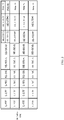
- a data part (HE-STF#1, HE-LTF#1, and Data#1) of a station 1 is sent on a target RU.
- a common physical layer preamble (including legacy preamble, RL-SIG, and HE-SIG-A) of the station 1 is sent on a fundamental channel unit (such as a 20 MHz channel) that includes the target RU, that is, sent in a fundamental channel unit in which the target RU is located.
- a channel on which the legacy preamble, the RL-SIG, and the HE-SIG-A are sent is in a minimum unit of 20 MHz.
- the legacy preamble, the RL-SIG, and the HE-SIG-A are not sent on another fundamental channel unit in BW.
- frequency domain resources occupied when other stations perform transmission are represented by dashed lines.
- the data part (including data or a MAC control signaling part) of the uplink station is sent on the allocated target RU.
- the target RU spans multiple fundamental channel units (for example, each fundamental channel unit is a 20 MHz channel), and the common physical layer preamble of the station is repeatedly sent on the multiple fundamental channel units spanned by the target RU.
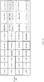
- a target RU of a station 1 spans two fundamental channel units.
- a data part of the station 1 (HE-STF#1, HE-LTF#1, and Data#1) is sent on the target RU, and a common physical layer preamble (including legacy preamble, RL-SIG, and HE-SIG-A) of the station 1 is repeatedly sent on the two 20 MHz channels spanned by the target RU, that is, common physical layer preambles on all the 20 MHz channels are the same.
- the legacy preamble, the RL-SIG, and the HE-SIG-A are not sent on another fundamental channel unit in entire channel BW.
- OFDMA PPDUs transmitted by other stations are represented by dashed lines.
- the foregoing repeated sending may further include multiplying the repeatedly-transmitted common physical layer preamble by a rotating factor, so as to reduce a peak-to-average ratio. This is not limited herein.
- a station when a station sends an uplink OFMDA PPDU, a data part of each station is transmitted on a target RU scheduled by an AP, and a common physical layer preamble (legacy preamble, RL-SIG, and HE-SIGA) is transmitted only on at least one fundamental channel unit (such as a 20 MHz channel) in which the target RU is located. If the target RU spans multiple 20 MHz channels, the legacy preamble, the RL-SIG, and the HE-SIGA are repeatedly transmitted on the multiple 20 MHz channels. In the method, disadvantages in the prior art are avoided, and another BSS station can contend for a 20 MHz channel without a data part, to improve spectrum utilization.
- a common physical layer preamble (legacy preamble, RL-SIG, and HE-SIGA) is transmitted only on at least one fundamental channel unit (such as a 20 MHz channel) in which the target RU is located. If the target RU spans multiple 20 MHz channels
- each station sends a common physical layer preamble only on a 20 MHz channel in which a target RU occupied by a data part is located. That is, the station prevents only the 20 MHz channel in which the data is located from being preempted by another BSS station.
- total transmission bandwidth 80 MHz
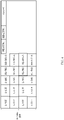
- the station 1 is scheduled by the AP to transmit data on a target RU in the first 20 MHz channel, and another station is scheduled to transmit data on another 20 MHz channel.
- a method for sending a common physical layer preamble (legacy preamble, RL-SIG, and HE-SIGA) by a station is shown in FIG. 6 . Because the common physical layer preamble is transmitted only on the first 20 MHz channel, a hidden node (another BSS station) of the station 1 may preempt another 20 MHz channel such as the second 20 MHz channel that is not protected by the station 1.
- the target RU is a default resource unit in a channel frequency domain resource center, and the target RU is not in any fundamental channel unit,
- the target RU allocated by the AP to the station STA is a default resource unit in a channel frequency domain resource center, and the target RU is not in any fundamental channel unit, such as an 80 MHz bandwidth channel frequency domain resource and a 160 MHz bandwidth channel frequency domain resource.
- FIG. 8 is a schematic diagram of an 80 MHz bandwidth channel frequency domain resource.
- an RU for example, a quantity of subcarriers is 26
- FIG. 9 is a schematic diagram of a 160 MHz bandwidth channel frequency domain resource.
- the channel frequency domain resource is equivalent to a combination of two 80 MHz bandwidth channel frequency domain resources. Therefore, for each 80 MHz bandwidth channel frequency domain resource, an RU is still not in any 20 MHz fundamental channel unit.
- the station may not send the common physical layer preamble, or the station repeatedly sends the common physical layer preamble on all fundamental channel units, or the station sends the common physical layer preamble on one or two fundamental channel units adjacent to the target RU.
- S502 The station receives an acknowledgement frame fed back for the OFDMA PPDU.
- the acknowledgement frame of the station is sent by the access point on an RU selected by the access point from the at least one fundamental channel unit; or the access point encapsulates the acknowledgement frame of the station as an encapsulation packet and then sends the encapsulation packet on an RU in the at least one fundamental channel unit, where the encapsulation packet includes acknowledgement frames fed back by the access point of multiple stations.
- the AP after receiving the uplink OFMDA PPDU, the AP replies to the OFMDA PPDU with the acknowledgement frame.
- acknowledgement frame There are generally two types of acknowledgement frames with which the AP replies.
- One type of acknowledgement frame is an OFMDA-BA (block acknowledgement)
- M-BA Multi-STA block acknowledgement
- acknowledgement frame obtained in a manner of combining the two types of frames, that is, an OFDMA M-BA frame. That is, multiple M-BA frames are sent by using an orthogonal OFDMA subchannel.
- the AP replies to the received uplink OFDMA PPDU with an OFDMA-BA or an OFDMA M-BA, the AP needs to transmit an acknowledgement frame of a station on at least one 20 MHz channel in which a target RU occupied by a transmitted data part of the station is located. If the target RU spans multiple 20 MHz channels, the AP may select one or more 20 MHz channels to transmit the acknowledgement frame of the station.
- the access point selects an RU from at least one 20 MHz channel in which the target RU is located to transmit the acknowledgement frame.
- the RU for transmitting the acknowledgement frame and the target RU may be the same or may be different.
- the access point may encapsulate acknowledgement frames of multiple stations as an encapsulation packet, and select an RU from the at least one 20 MHz channel to transmit the encapsulation packet.
- FIG. 6 is used as an example for description. If the AP replies with an OFDMA-BA, the AP needs to transmit an acknowledgement frame (Ack (acknowledgement frame) or BA) of the station 1 on the first 20 MHz fundamental channel unit. As shown in FIG. 10 , the acknowledgement frame of the station 1 is transmitted on the first 20 MHz fundamental channel unit. If the AP replies with an OFDMA-M-BA, the M-BA frame transmitted on the first 20 MHz channel by the AP needs to include the acknowledgement frame of the station 1.
- Ack acknowledgement frame
- BA acknowledgement frame
- the AP needs to transmit a preset frame structure on the primary 20 MHz channel.
- the preset frame structure may include but is not limited to a quality of service null frame (quality of service null frame, QoS Null), a padding data frame, or a data frame, a control frame, and a management frame that are transmitted to a station. Therefore, the primary 20 MHz channel is prevented from being preempted by another station, and accordingly, a transmission opportunity is not lost.
- a reason why the acknowledgement frame is not on the primary 20 MHz channel may include but is limited to a reason that the AP does not correctly receive information on the primary 20 MHz channel.
- the AP needs to transmit a preset frame structure on the 20 MHz channel.
- the preset frame structure may include but is not limited to a QoS null frame, a padding data frame, or a data frame, a control frame, and a management frame that are transmitted to a station. Therefore, the 20 MHz channel is prevented from being preempted by another station, and accordingly, a transmission opportunity on the 20 MHz channel is not lost.
- the acknowledgement frame for the downlink OFDMA PPDU is sent by the AP.
- legacy preamble, RL-SIG, and HE-SIG-A are repeatedly transmitted on each 20 MHz channel, and HE-SIG-B is transmitted on a unit of 20 MHz, and HE-SIG-B transmitted on 20 MHz channels may be different.
- the HE-SIG-B is divided into HE-SIG-B 1 and HE-SIG-B2, that is, a [1 2 1 2] transmission structure is used. That is, same HE-SIG-B is transmitted on spaced fundamental channel units.
- the station receives the trigger frame sent by the access point.
- the trigger frame includes the identifier of the target RU allocated to the station.
- the station sends the uplink OFDMA PPDU.
- the data part of the OFDMA PPDU is sent on the target RU, and the common physical layer preamble of the OFDMA PPDU is sent on at least one fundamental channel unit in which the target RU is located.
- the station receives the acknowledgement frame fed back for the OFDMA PPDU.
- a common physical layer preamble of an OFDMA PPDU is sent only on at least one fundamental channel unit in which an allocated target RU is located. Therefore, spectrum resources occupied by the common physical layer preamble are reduced, so that more stations contend for access to a channel, thereby improving spectrum utilization.
- FIG. 11 is a schematic structural diagram of a data transmission apparatus provided in an embodiment of the present invention.
- the data transmission apparatus may be applied to a station such as any station STA in FIG. 2 .
- the data transmission apparatus in this embodiment includes a receiving module 100 and a sending module 101.
- the receiving module 100 is configured to receive a trigger frame sent by an access point.
- the trigger frame includes an identifier of a target frequency domain resource unit RU allocated to the station.
- the sending module 101 is configured to send an uplink orthogonal frequency division multiple access physical layer protocol data unit OFDMA PPDU.
- a data part of the OFDMA PPDU is sent on the target RU, and a common physical layer preamble of the OFDMA PPDU is sent on at least one fundamental channel unit in which the target RU is located.
- the fundamental channel unit in which the target RU is located includes at least two fundamental channel units
- the common physical layer preamble of the OFDMA PPDU is repeatedly sent on each of the at least two fundamental channel units.
- the common physical layer preamble includes a legacy preamble legacy preamble field, a repeated legacy-signal (RL-SIG) field, and a high efficiency signaling HE-SIG-A field.
- the target RU is a default resource unit in a channel frequency domain resource center, and the target RU is not in any fundamental channel unit,
- the receiving module 100 is further configured to receive an acknowledgement frame fed back for the OFDMA PPDU.
- the acknowledgement frame of the station is sent by the access point on an RU selected by the access point from the at least one fundamental channel unit; or the access point encapsulates the acknowledgement frame of the station as an encapsulation packet and then sends the encapsulation packet on an RU in the at least one fundamental channel unit, where the encapsulation packet includes acknowledgement frames fed back by the access point for multiple stations.
- the access point transmits a preset frame structure on the primary fundamental channel unit.
- the station receives the trigger frame sent by the access point.
- the trigger frame includes the identifier of the target RU allocated to the station.
- the station sends the uplink OFDMA PPDU.
- the data part of the OFDMA PPDU is sent on the target RU, and the common physical layer preamble of the OFDMA PPDU is sent on the at least one fundamental channel unit in which the target RU is located.
- the station receives the acknowledgement frame fed back for the OFDMA PPDU.
- a common physical layer preamble of an OFDMA PPDU is sent only on at least one fundamental channel unit in which an allocated target RU is located. Therefore, spectrum resources occupied by the common physical layer preamble are reduced, so that more stations contend for access to a channel, thereby improving spectrum utilization.
- FIG. 12 is a schematic structural diagram of another data transmission apparatus provided in an embodiment of the present invention.
- the data transmission apparatus may be applied to a station.
- the data transmission apparatus 1000 includes a processor 1010, a memory 1020, and a transceiver 1030.
- a station to which the data transmission apparatus is applied may be the STA shown in FIG. 1 or the STA shown in FIG. 2 .
- the processor 1010 controls an operation of the data transmission apparatus 1000.
- the memory 1020 may include a read-only memory and a random access memory, and provide an instruction and data to the processor 1010.
- the processor may be a general-purpose processor, a digital signal processor, an application-specific integrated circuit, a field programmable gate array, or another programmable logic device.
- a part of the memory 1020 may further include a nonvolatile random access memory (NVRAM). All components of the data transmission apparatus 1000 are coupled together by using a bus 1040.
- the bus system 1040 further includes a power bus, a control bus, and a status signal bus. However, for clear description, various types of buses in the figure are marked as the bus system 1040. It should be noted that, the description about the data transmission apparatus may be applied to a subsequent embodiment.
- the transceiver 1030 is configured to receive a trigger frame sent by an access point.
- the trigger frame includes an identifier of a target frequency domain resource unit RU allocated to the station.
- the transceiver 1030 is further configured to send an uplink orthogonal frequency division multiple access physical layer protocol data unit OFDMA PPDU.
- a data part of the OFDMA PPDU is sent on the target RU, and a common physical layer preamble of the OFDMA PPDU is sent on at least one fundamental channel unit in which the target RU is located.
- the transceiver 1030 is further configured to receive an acknowledgement frame fed back for the OFDMA PPDU.
- the fundamental channel unit in which the target RU is located includes at least two fundamental channel units
- the common physical layer preamble of the OFDMA PPDU is repeatedly sent on each of the at least two fundamental channel units.
- the common physical layer preamble includes a legacy preamble legacy preamble field, a repeated legacy-signal (RL-SIG) field, and a high efficiency signaling HE-SIG-A field.
- the target RU is a default resource unit in a channel frequency domain resource center, and the target RU is not in any fundamental channel unit,
- the acknowledgement frame of the station is sent by the access point on an RU selected by the access point from the at least one fundamental channel unit; or the access point encapsulates the acknowledgement frame of the station as an encapsulation packet and then sends the encapsulation packet on an RU in the at least one fundamental channel unit, where the encapsulation packet includes acknowledgement frames fed back by the access point of multiple stations.
- the access point transmits a preset frame structure on the primary fundamental channel unit.
- the program may be stored in a computer readable storage medium. When the program runs, the processes of the methods in the embodiments are performed.
- the foregoing storage medium includes: any medium that can store program code, such as a read-only memory (Read-Only Memory, ROM), a random access memory (Random Access Memory, RAM), a magnetic disk, or an optical disc.
Landscapes
- Engineering & Computer Science (AREA)
- Signal Processing (AREA)
- Computer Networks & Wireless Communication (AREA)
- Mobile Radio Communication Systems (AREA)
Applications Claiming Priority (3)
| Application Number | Priority Date | Filing Date | Title |
|---|---|---|---|
| CN201610416585.4A CN107509252B (zh) | 2016-06-14 | 2016-06-14 | 一种数据传输方法及装置 |
| PCT/CN2017/084378 WO2017215386A1 (fr) | 2016-06-14 | 2017-05-15 | Procédé et dispositif de transmission de données |
| EP17812497.0A EP3413661B1 (fr) | 2016-06-14 | 2017-05-15 | Procédé et dispositif de transmission de données |
Related Parent Applications (2)
| Application Number | Title | Priority Date | Filing Date |
|---|---|---|---|
| EP17812497.0A Division-Into EP3413661B1 (fr) | 2016-06-14 | 2017-05-15 | Procédé et dispositif de transmission de données |
| EP17812497.0A Division EP3413661B1 (fr) | 2016-06-14 | 2017-05-15 | Procédé et dispositif de transmission de données |
Publications (3)
| Publication Number | Publication Date |
|---|---|
| EP3986062A1 true EP3986062A1 (fr) | 2022-04-20 |
| EP3986062C0 EP3986062C0 (fr) | 2024-01-03 |
| EP3986062B1 EP3986062B1 (fr) | 2024-01-03 |
Family
ID=60664336
Family Applications (2)
| Application Number | Title | Priority Date | Filing Date |
|---|---|---|---|
| EP21184137.4A Active EP3986062B1 (fr) | 2016-06-14 | 2017-05-15 | Procédé et appareil de transmission de données |
| EP17812497.0A Active EP3413661B1 (fr) | 2016-06-14 | 2017-05-15 | Procédé et dispositif de transmission de données |
Family Applications After (1)
| Application Number | Title | Priority Date | Filing Date |
|---|---|---|---|
| EP17812497.0A Active EP3413661B1 (fr) | 2016-06-14 | 2017-05-15 | Procédé et dispositif de transmission de données |
Country Status (14)
| Country | Link |
|---|---|
| US (3) | US20190116014A1 (fr) |
| EP (2) | EP3986062B1 (fr) |
| JP (2) | JP6705009B2 (fr) |
| KR (1) | KR102181737B1 (fr) |
| CN (3) | CN113472499A (fr) |
| AU (1) | AU2017285829B2 (fr) |
| BR (1) | BR112018067557A2 (fr) |
| CA (1) | CA3015425C (fr) |
| ES (1) | ES2899181T3 (fr) |
| MX (1) | MX393859B (fr) |
| MY (1) | MY198824A (fr) |
| PL (1) | PL3413661T3 (fr) |
| RU (1) | RU2711509C1 (fr) |
| WO (1) | WO2017215386A1 (fr) |
Families Citing this family (19)
| Publication number | Priority date | Publication date | Assignee | Title |
|---|---|---|---|---|
| WO2017018801A1 (fr) * | 2015-07-29 | 2017-02-02 | Lg Electronics Inc. | Procédé et appareil de transmission de données dans un système de communication sans fil |
| US10701707B2 (en) * | 2017-03-28 | 2020-06-30 | Arris Enterprises Llc | Allocation of wireless channels for preferred stations |
| US11044056B2 (en) * | 2018-02-01 | 2021-06-22 | Mediatek Singapore Pte. Ltd. | Enhanced resource unit allocation schemes for OFDMA transmission in WLAN |
| US11949610B2 (en) | 2019-06-28 | 2024-04-02 | Lg Electronics Inc. | Technique for forming midamble in wireless communication system |
| US11277794B2 (en) * | 2019-07-31 | 2022-03-15 | Hewlett Packard Enterprise Development Lp | Power save aware RU allocation |
| CN110784297B (zh) * | 2019-10-31 | 2022-05-24 | 普联技术有限公司 | 一种资源单元的分配方法及装置 |
| CN113498175B (zh) * | 2020-03-20 | 2024-11-01 | 华为技术有限公司 | 一种通信方法、设备及系统 |
| CN113596927A (zh) * | 2020-04-30 | 2021-11-02 | 华为技术有限公司 | 无线通信传输方法及相关装置 |
| CN113597000B (zh) * | 2020-04-30 | 2024-06-28 | 华为技术有限公司 | 传输无线局域网分组结构ppdu的方法、相关设备以及系统 |
| US11882062B2 (en) | 2020-06-16 | 2024-01-23 | Nxp Usa, Inc. | Method and apparatus for wireless communications |
| US11937230B2 (en) * | 2020-06-16 | 2024-03-19 | Nxp Usa, Inc. | Method and apparatus for wireless communications |
| US12520285B2 (en) | 2020-06-25 | 2026-01-06 | Apple Inc. | Low-latency communication in a WLAN |
| CN114143877A (zh) * | 2020-09-04 | 2022-03-04 | 华为技术有限公司 | 资源单元指示方法、接入点及站点 |
| US11616609B2 (en) | 2021-05-12 | 2023-03-28 | Cisco Technology, Inc. | Reducing latency in OFDMA using front ends with adaptive linearity |
| CN115442894A (zh) * | 2021-06-03 | 2022-12-06 | 华为技术有限公司 | 一种物理层协议数据单元、触发帧的传输方法以及装置 |
| CN115883304A (zh) * | 2021-08-13 | 2023-03-31 | 华为技术有限公司 | 一种数据传输方法及通信装置 |
| CN114500884B (zh) * | 2022-01-06 | 2023-12-01 | 杭州海康威视数字技术股份有限公司 | 资源单元的分配方法、装置、设备及系统 |
| CN118057894A (zh) * | 2022-11-18 | 2024-05-21 | 华为技术有限公司 | 通信方法、装置、系统及存储介质 |
| CN115623596B (zh) * | 2022-12-20 | 2023-04-07 | 翱捷科技(深圳)有限公司 | 上行链路的ofdma处理方法、装置、系统及存储介质 |
Citations (2)
| Publication number | Priority date | Publication date | Assignee | Title |
|---|---|---|---|---|
| WO2016089059A1 (fr) * | 2014-12-05 | 2016-06-09 | 엘지전자(주) | Procédé de transmission de données dans un système de communication sans fil et son dispositif |
| US20160165574A1 (en) * | 2014-12-05 | 2016-06-09 | Marvell World Trade Ltd. | Trigger frame format for orthogonal frequency division multiple access (ofdma) communication |
Family Cites Families (15)
| Publication number | Priority date | Publication date | Assignee | Title |
|---|---|---|---|---|
| EP2491663B1 (fr) * | 2009-10-23 | 2015-07-29 | Marvell World Trade Ltd. | Indication de séquence d'apprentissage pour réseau WLAN |
| CN102714534B (zh) * | 2009-12-03 | 2015-01-07 | Lg电子株式会社 | 在无线ran系统中发送帧的方法和装置 |
| US9350428B2 (en) * | 2010-12-01 | 2016-05-24 | Lg Electronics Inc. | Method and apparatus of link adaptation in wireless local area network |
| US9781627B2 (en) * | 2013-04-08 | 2017-10-03 | Qualcomm Incorporated | Systems and methods for generating and decoding short control frames in wireless communications |
| US10205573B2 (en) * | 2013-09-13 | 2019-02-12 | Futurewei Technologies, Inc. | System and method for OFDMA PS-poll transmission |
| US9445226B2 (en) * | 2014-01-31 | 2016-09-13 | Aruba Networks, Inc. | Method for improving location accuracy in multi-channel wireless networks |
| US20160021678A1 (en) * | 2014-07-15 | 2016-01-21 | Qualcomm Incorporated | Signaling techniques for ul mu mimo/ofdma transmission |
| KR20160019383A (ko) * | 2014-08-11 | 2016-02-19 | 뉴라컴 인코포레이티드 | 고효율 무선랜의 물리계층 프로토콜 데이터 유닛 포맷 |
| AU2015304131B2 (en) * | 2014-08-21 | 2018-08-02 | Lg Electronics Inc. | Method for uplink transmission in wireless communication system and apparatus therefor |
| EP3188536B1 (fr) * | 2014-08-29 | 2021-04-14 | Kabushiki Kaisha Toshiba | Circuit intégré pour communication sans fil, terminal de communication sans fil et procédé de communication sans fil |
| CN105517157A (zh) * | 2014-09-24 | 2016-04-20 | 中兴通讯股份有限公司 | 无线局域网中上行多用户数据传输方法、系统及站点 |
| CN105517118A (zh) * | 2014-09-24 | 2016-04-20 | 中兴通讯股份有限公司 | 无线局域网中下行多用户数据传输方法、系统及接入点 |
| US10218555B2 (en) * | 2015-03-06 | 2019-02-26 | Intel IP Corporation | Usage of early bits in wireless communications |
| US10742285B1 (en) * | 2015-11-13 | 2020-08-11 | Marvell International Ltd. | Explicit multiuser beamforming training in a wireless local area network |
| US20170142662A1 (en) * | 2015-11-17 | 2017-05-18 | Ilan Sutskover | Methods for controlling uplink transmit power in a wireless network |
-
2016
- 2016-06-14 CN CN202110656531.6A patent/CN113472499A/zh active Pending
- 2016-06-14 CN CN201610416585.4A patent/CN107509252B/zh active Active
- 2016-06-14 CN CN201911071577.0A patent/CN110912668B/zh active Active
-
2017
- 2017-05-15 WO PCT/CN2017/084378 patent/WO2017215386A1/fr not_active Ceased
- 2017-05-15 EP EP21184137.4A patent/EP3986062B1/fr active Active
- 2017-05-15 EP EP17812497.0A patent/EP3413661B1/fr active Active
- 2017-05-15 CA CA3015425A patent/CA3015425C/fr active Active
- 2017-05-15 ES ES17812497T patent/ES2899181T3/es active Active
- 2017-05-15 MX MX2018012718A patent/MX393859B/es unknown
- 2017-05-15 MY MYPI2018702968A patent/MY198824A/en unknown
- 2017-05-15 KR KR1020187026018A patent/KR102181737B1/ko active Active
- 2017-05-15 PL PL17812497T patent/PL3413661T3/pl unknown
- 2017-05-15 AU AU2017285829A patent/AU2017285829B2/en active Active
- 2017-05-15 BR BR112018067557A patent/BR112018067557A2/pt not_active Application Discontinuation
- 2017-05-15 JP JP2018549319A patent/JP6705009B2/ja active Active
- 2017-05-15 RU RU2018135074A patent/RU2711509C1/ru active
-
2018
- 2018-12-13 US US16/218,989 patent/US20190116014A1/en not_active Abandoned
-
2020
- 2020-04-06 US US16/840,925 patent/US20200235889A1/en not_active Abandoned
- 2020-05-13 JP JP2020084620A patent/JP6907382B2/ja active Active
-
2025
- 2025-01-16 US US19/023,379 patent/US20250233711A1/en active Pending
Patent Citations (3)
| Publication number | Priority date | Publication date | Assignee | Title |
|---|---|---|---|---|
| WO2016089059A1 (fr) * | 2014-12-05 | 2016-06-09 | 엘지전자(주) | Procédé de transmission de données dans un système de communication sans fil et son dispositif |
| US20160165574A1 (en) * | 2014-12-05 | 2016-06-09 | Marvell World Trade Ltd. | Trigger frame format for orthogonal frequency division multiple access (ofdma) communication |
| EP3229434A1 (fr) * | 2014-12-05 | 2017-10-11 | LG Electronics Inc. | Procédé de transmission de données dans un système de communication sans fil et son dispositif |
Also Published As
| Publication number | Publication date |
|---|---|
| US20200235889A1 (en) | 2020-07-23 |
| EP3986062C0 (fr) | 2024-01-03 |
| EP3413661A1 (fr) | 2018-12-12 |
| JP2020145712A (ja) | 2020-09-10 |
| PL3413661T3 (pl) | 2022-01-17 |
| CA3015425C (fr) | 2020-12-29 |
| MX393859B (es) | 2025-03-24 |
| US20250233711A1 (en) | 2025-07-17 |
| MX2018012718A (es) | 2019-01-30 |
| JP6907382B2 (ja) | 2021-07-21 |
| MY198824A (en) | 2023-09-29 |
| JP6705009B2 (ja) | 2020-06-03 |
| CN107509252B (zh) | 2021-06-15 |
| EP3413661B1 (fr) | 2021-08-25 |
| BR112018067557A2 (pt) | 2019-01-08 |
| AU2017285829B2 (en) | 2019-11-07 |
| JP2019511875A (ja) | 2019-04-25 |
| CN113472499A (zh) | 2021-10-01 |
| EP3413661A4 (fr) | 2019-02-27 |
| ES2899181T3 (es) | 2022-03-10 |
| AU2017285829A1 (en) | 2018-09-06 |
| EP3986062B1 (fr) | 2024-01-03 |
| CN110912668B (zh) | 2020-10-27 |
| KR102181737B1 (ko) | 2020-11-23 |
| CN107509252A (zh) | 2017-12-22 |
| US20190116014A1 (en) | 2019-04-18 |
| WO2017215386A1 (fr) | 2017-12-21 |
| CN110912668A (zh) | 2020-03-24 |
| RU2711509C1 (ru) | 2020-01-17 |
| KR20180113560A (ko) | 2018-10-16 |
| CA3015425A1 (fr) | 2017-12-21 |
Similar Documents
| Publication | Publication Date | Title |
|---|---|---|
| US20250233711A1 (en) | Data transmission method and apparatus | |
| EP3993491B1 (fr) | Procédé et appareil de communication à liaisons multiples | |
| US20220061090A1 (en) | Nr-u wideband enhancements | |
| CN107432036B (zh) | 上行多用户传输触发帧的发送方法、接入点和站点 | |
| US10693618B2 (en) | Multiplexed messaging in wireless network | |
| US9820300B2 (en) | Method and apparatus for receiving downlink frame in wireless LAN | |
| WO2015102228A1 (fr) | Procédé et appareil de transmission de trame de liaison montante dans un lan sans fil | |
| JP2017522810A (ja) | 無線ネットワーク内の重複伝送を可能にすること |
Legal Events
| Date | Code | Title | Description |
|---|---|---|---|
| PUAI | Public reference made under article 153(3) epc to a published international application that has entered the european phase |
Free format text: ORIGINAL CODE: 0009012 |
|
| STAA | Information on the status of an ep patent application or granted ep patent |
Free format text: STATUS: THE APPLICATION HAS BEEN PUBLISHED |
|
| AC | Divisional application: reference to earlier application |
Ref document number: 3413661 Country of ref document: EP Kind code of ref document: P |
|
| AK | Designated contracting states |
Kind code of ref document: A1 Designated state(s): AL AT BE BG CH CY CZ DE DK EE ES FI FR GB GR HR HU IE IS IT LI LT LU LV MC MK MT NL NO PL PT RO RS SE SI SK SM TR |
|
| STAA | Information on the status of an ep patent application or granted ep patent |
Free format text: STATUS: REQUEST FOR EXAMINATION WAS MADE |
|
| 17P | Request for examination filed |
Effective date: 20221020 |
|
| RBV | Designated contracting states (corrected) |
Designated state(s): AL AT BE BG CH CY CZ DE DK EE ES FI FR GB GR HR HU IE IS IT LI LT LU LV MC MK MT NL NO PL PT RO RS SE SI SK SM TR |
|
| STAA | Information on the status of an ep patent application or granted ep patent |
Free format text: STATUS: EXAMINATION IS IN PROGRESS |
|
| 17Q | First examination report despatched |
Effective date: 20230202 |
|
| GRAP | Despatch of communication of intention to grant a patent |
Free format text: ORIGINAL CODE: EPIDOSNIGR1 |
|
| STAA | Information on the status of an ep patent application or granted ep patent |
Free format text: STATUS: GRANT OF PATENT IS INTENDED |
|
| INTG | Intention to grant announced |
Effective date: 20230809 |
|
| GRAS | Grant fee paid |
Free format text: ORIGINAL CODE: EPIDOSNIGR3 |
|
| GRAA | (expected) grant |
Free format text: ORIGINAL CODE: 0009210 |
|
| STAA | Information on the status of an ep patent application or granted ep patent |
Free format text: STATUS: THE PATENT HAS BEEN GRANTED |
|
| AC | Divisional application: reference to earlier application |
Ref document number: 3413661 Country of ref document: EP Kind code of ref document: P |
|
| AK | Designated contracting states |
Kind code of ref document: B1 Designated state(s): AL AT BE BG CH CY CZ DE DK EE ES FI FR GB GR HR HU IE IS IT LI LT LU LV MC MK MT NL NO PL PT RO RS SE SI SK SM TR |
|
| REG | Reference to a national code |
Ref country code: GB Ref legal event code: FG4D |
|
| REG | Reference to a national code |
Ref country code: CH Ref legal event code: EP |
|
| REG | Reference to a national code |
Ref country code: DE Ref legal event code: R096 Ref document number: 602017078258 Country of ref document: DE |
|
| REG | Reference to a national code |
Ref country code: IE Ref legal event code: FG4D |
|
| U01 | Request for unitary effect filed |
Effective date: 20240103 |
|
| U07 | Unitary effect registered |
Designated state(s): AT BE BG DE DK EE FI FR IT LT LU LV MT NL PT SE SI Effective date: 20240108 |
|
| PG25 | Lapsed in a contracting state [announced via postgrant information from national office to epo] |
Ref country code: ES Free format text: LAPSE BECAUSE OF FAILURE TO SUBMIT A TRANSLATION OF THE DESCRIPTION OR TO PAY THE FEE WITHIN THE PRESCRIBED TIME-LIMIT Effective date: 20240103 |
|
| PG25 | Lapsed in a contracting state [announced via postgrant information from national office to epo] |
Ref country code: ES Free format text: LAPSE BECAUSE OF FAILURE TO SUBMIT A TRANSLATION OF THE DESCRIPTION OR TO PAY THE FEE WITHIN THE PRESCRIBED TIME-LIMIT Effective date: 20240103 |
|
| PG25 | Lapsed in a contracting state [announced via postgrant information from national office to epo] |
Ref country code: IS Free format text: LAPSE BECAUSE OF FAILURE TO SUBMIT A TRANSLATION OF THE DESCRIPTION OR TO PAY THE FEE WITHIN THE PRESCRIBED TIME-LIMIT Effective date: 20240503 |
|
| U20 | Renewal fee for the european patent with unitary effect paid |
Year of fee payment: 8 Effective date: 20240531 |
|
| PG25 | Lapsed in a contracting state [announced via postgrant information from national office to epo] |
Ref country code: GR Free format text: LAPSE BECAUSE OF FAILURE TO SUBMIT A TRANSLATION OF THE DESCRIPTION OR TO PAY THE FEE WITHIN THE PRESCRIBED TIME-LIMIT Effective date: 20240404 |
|
| PG25 | Lapsed in a contracting state [announced via postgrant information from national office to epo] |
Ref country code: RS Free format text: LAPSE BECAUSE OF FAILURE TO SUBMIT A TRANSLATION OF THE DESCRIPTION OR TO PAY THE FEE WITHIN THE PRESCRIBED TIME-LIMIT Effective date: 20240403 Ref country code: HR Free format text: LAPSE BECAUSE OF FAILURE TO SUBMIT A TRANSLATION OF THE DESCRIPTION OR TO PAY THE FEE WITHIN THE PRESCRIBED TIME-LIMIT Effective date: 20240103 |
|
| PG25 | Lapsed in a contracting state [announced via postgrant information from national office to epo] |
Ref country code: CZ Free format text: LAPSE BECAUSE OF FAILURE TO SUBMIT A TRANSLATION OF THE DESCRIPTION OR TO PAY THE FEE WITHIN THE PRESCRIBED TIME-LIMIT Effective date: 20240103 |
|
| PG25 | Lapsed in a contracting state [announced via postgrant information from national office to epo] |
Ref country code: RS Free format text: LAPSE BECAUSE OF FAILURE TO SUBMIT A TRANSLATION OF THE DESCRIPTION OR TO PAY THE FEE WITHIN THE PRESCRIBED TIME-LIMIT Effective date: 20240403 Ref country code: NO Free format text: LAPSE BECAUSE OF FAILURE TO SUBMIT A TRANSLATION OF THE DESCRIPTION OR TO PAY THE FEE WITHIN THE PRESCRIBED TIME-LIMIT Effective date: 20240403 Ref country code: IS Free format text: LAPSE BECAUSE OF FAILURE TO SUBMIT A TRANSLATION OF THE DESCRIPTION OR TO PAY THE FEE WITHIN THE PRESCRIBED TIME-LIMIT Effective date: 20240503 Ref country code: HR Free format text: LAPSE BECAUSE OF FAILURE TO SUBMIT A TRANSLATION OF THE DESCRIPTION OR TO PAY THE FEE WITHIN THE PRESCRIBED TIME-LIMIT Effective date: 20240103 Ref country code: GR Free format text: LAPSE BECAUSE OF FAILURE TO SUBMIT A TRANSLATION OF THE DESCRIPTION OR TO PAY THE FEE WITHIN THE PRESCRIBED TIME-LIMIT Effective date: 20240404 Ref country code: CZ Free format text: LAPSE BECAUSE OF FAILURE TO SUBMIT A TRANSLATION OF THE DESCRIPTION OR TO PAY THE FEE WITHIN THE PRESCRIBED TIME-LIMIT Effective date: 20240103 |
|
| PG25 | Lapsed in a contracting state [announced via postgrant information from national office to epo] |
Ref country code: PL Free format text: LAPSE BECAUSE OF FAILURE TO SUBMIT A TRANSLATION OF THE DESCRIPTION OR TO PAY THE FEE WITHIN THE PRESCRIBED TIME-LIMIT Effective date: 20240103 |
|
| PG25 | Lapsed in a contracting state [announced via postgrant information from national office to epo] |
Ref country code: PL Free format text: LAPSE BECAUSE OF FAILURE TO SUBMIT A TRANSLATION OF THE DESCRIPTION OR TO PAY THE FEE WITHIN THE PRESCRIBED TIME-LIMIT Effective date: 20240103 |
|
| REG | Reference to a national code |
Ref country code: DE Ref legal event code: R097 Ref document number: 602017078258 Country of ref document: DE |
|
| PG25 | Lapsed in a contracting state [announced via postgrant information from national office to epo] |
Ref country code: SM Free format text: LAPSE BECAUSE OF FAILURE TO SUBMIT A TRANSLATION OF THE DESCRIPTION OR TO PAY THE FEE WITHIN THE PRESCRIBED TIME-LIMIT Effective date: 20240103 |
|
| PG25 | Lapsed in a contracting state [announced via postgrant information from national office to epo] |
Ref country code: SK Free format text: LAPSE BECAUSE OF FAILURE TO SUBMIT A TRANSLATION OF THE DESCRIPTION OR TO PAY THE FEE WITHIN THE PRESCRIBED TIME-LIMIT Effective date: 20240103 |
|
| PG25 | Lapsed in a contracting state [announced via postgrant information from national office to epo] |
Ref country code: SM Free format text: LAPSE BECAUSE OF FAILURE TO SUBMIT A TRANSLATION OF THE DESCRIPTION OR TO PAY THE FEE WITHIN THE PRESCRIBED TIME-LIMIT Effective date: 20240103 Ref country code: SK Free format text: LAPSE BECAUSE OF FAILURE TO SUBMIT A TRANSLATION OF THE DESCRIPTION OR TO PAY THE FEE WITHIN THE PRESCRIBED TIME-LIMIT Effective date: 20240103 Ref country code: RO Free format text: LAPSE BECAUSE OF FAILURE TO SUBMIT A TRANSLATION OF THE DESCRIPTION OR TO PAY THE FEE WITHIN THE PRESCRIBED TIME-LIMIT Effective date: 20240103 |
|
| PLBE | No opposition filed within time limit |
Free format text: ORIGINAL CODE: 0009261 |
|
| STAA | Information on the status of an ep patent application or granted ep patent |
Free format text: STATUS: NO OPPOSITION FILED WITHIN TIME LIMIT |
|
| 26N | No opposition filed |
Effective date: 20241007 |
|
| REG | Reference to a national code |
Ref country code: CH Ref legal event code: PL |
|
| PG25 | Lapsed in a contracting state [announced via postgrant information from national office to epo] |
Ref country code: MC Free format text: LAPSE BECAUSE OF FAILURE TO SUBMIT A TRANSLATION OF THE DESCRIPTION OR TO PAY THE FEE WITHIN THE PRESCRIBED TIME-LIMIT Effective date: 20240103 |
|
| GBPC | Gb: european patent ceased through non-payment of renewal fee |
Effective date: 20240515 |
|
| PG25 | Lapsed in a contracting state [announced via postgrant information from national office to epo] |
Ref country code: MC Free format text: LAPSE BECAUSE OF FAILURE TO SUBMIT A TRANSLATION OF THE DESCRIPTION OR TO PAY THE FEE WITHIN THE PRESCRIBED TIME-LIMIT Effective date: 20240103 Ref country code: CH Free format text: LAPSE BECAUSE OF NON-PAYMENT OF DUE FEES Effective date: 20240531 |
|
| PG25 | Lapsed in a contracting state [announced via postgrant information from national office to epo] |
Ref country code: IE Free format text: LAPSE BECAUSE OF NON-PAYMENT OF DUE FEES Effective date: 20240515 |
|
| PG25 | Lapsed in a contracting state [announced via postgrant information from national office to epo] |
Ref country code: GB Free format text: LAPSE BECAUSE OF NON-PAYMENT OF DUE FEES Effective date: 20240515 |
|
| U20 | Renewal fee for the european patent with unitary effect paid |
Year of fee payment: 9 Effective date: 20250602 |
|
| PG25 | Lapsed in a contracting state [announced via postgrant information from national office to epo] |
Ref country code: CY Free format text: LAPSE BECAUSE OF FAILURE TO SUBMIT A TRANSLATION OF THE DESCRIPTION OR TO PAY THE FEE WITHIN THE PRESCRIBED TIME-LIMIT; INVALID AB INITIO Effective date: 20170515 |
|
| PG25 | Lapsed in a contracting state [announced via postgrant information from national office to epo] |
Ref country code: HU Free format text: LAPSE BECAUSE OF FAILURE TO SUBMIT A TRANSLATION OF THE DESCRIPTION OR TO PAY THE FEE WITHIN THE PRESCRIBED TIME-LIMIT; INVALID AB INITIO Effective date: 20170515 |