EP3986082A1 - Verfahren und vorrichtung zum aktualisieren von gateways auf benutzerebene, computerlesbares speichermedium und kommunikationssystem - Google Patents
Verfahren und vorrichtung zum aktualisieren von gateways auf benutzerebene, computerlesbares speichermedium und kommunikationssystem Download PDFInfo
- Publication number
- EP3986082A1 EP3986082A1 EP21195715.4A EP21195715A EP3986082A1 EP 3986082 A1 EP3986082 A1 EP 3986082A1 EP 21195715 A EP21195715 A EP 21195715A EP 3986082 A1 EP3986082 A1 EP 3986082A1
- Authority
- EP
- European Patent Office
- Prior art keywords
- pdn connection
- plane gateway
- mme
- request message
- message
- Prior art date
- Legal status (The legal status is an assumption and is not a legal conclusion. Google has not performed a legal analysis and makes no representation as to the accuracy of the status listed.)
- Granted
Links
Images


Classifications
-
- H—ELECTRICITY
- H04—ELECTRIC COMMUNICATION TECHNIQUE
- H04W—WIRELESS COMMUNICATION NETWORKS
- H04W8/00—Network data management
- H04W8/02—Processing of mobility data, e.g. registration information at HLR [Home Location Register] or VLR [Visitor Location Register]; Transfer of mobility data, e.g. between HLR, VLR or external networks
- H04W8/08—Mobility data transfer
-
- H—ELECTRICITY
- H04—ELECTRIC COMMUNICATION TECHNIQUE
- H04W—WIRELESS COMMUNICATION NETWORKS
- H04W76/00—Connection management
- H04W76/10—Connection setup
- H04W76/12—Setup of transport tunnels
-
- H—ELECTRICITY
- H04—ELECTRIC COMMUNICATION TECHNIQUE
- H04W—WIRELESS COMMUNICATION NETWORKS
- H04W64/00—Locating users or terminals or network equipment for network management purposes, e.g. mobility management
-
- H—ELECTRICITY
- H04—ELECTRIC COMMUNICATION TECHNIQUE
- H04W—WIRELESS COMMUNICATION NETWORKS
- H04W64/00—Locating users or terminals or network equipment for network management purposes, e.g. mobility management
- H04W64/003—Locating users or terminals or network equipment for network management purposes, e.g. mobility management locating network equipment
-
- H—ELECTRICITY
- H04—ELECTRIC COMMUNICATION TECHNIQUE
- H04W—WIRELESS COMMUNICATION NETWORKS
- H04W76/00—Connection management
- H04W76/10—Connection setup
- H04W76/19—Connection re-establishment
-
- H—ELECTRICITY
- H04—ELECTRIC COMMUNICATION TECHNIQUE
- H04W—WIRELESS COMMUNICATION NETWORKS
- H04W88/00—Devices specially adapted for wireless communication networks, e.g. terminals, base stations or access point devices
- H04W88/16—Gateway arrangements
Definitions
- the present invention relates to the field of communications technologies, and in particular, to a user plane gateway updating method and apparatus.
- System architecture evolution is an upgrade plan of the 3GPP for a core network architecture of an LTE wireless communications standard.
- An SAE architecture is shown in FIG. 1 .
- TAU Tracking Area Update
- a TA Tracking Area
- a TA Tracking Area is a geographical area formed by continuously covered cells, and is used to manage a location of a UE that is in an idle state.
- a gateway still needs to keep a large quantity of external signaling interfaces.
- the large quantity of external signaling interfaces of the gateway bring a large amount of interface signaling.
- a gateway that uses a dedicated hardware platform does not have strong signaling processing performance, and therefore, easily becomes a bottleneck.
- Software-defined networking (Software Defined Network, SDN) provides an effective way to resolve the bottleneck problem of the gateway in signaling processing.
- An SDN-based SAE architecture is shown in FIG. 2 .
- GW-Us are further moved downwards and deployed in a distributed manner, implementing an architecture of distributed GW-U deployment shown in FIG. 3 .
- Embodiments of the present invention provide a user plane gateway updating method and apparatus, so as to resolve a prior-art technical problem that GW-U updating cannot be implemented when neither an MME nor a GW-C changes.
- a first aspect of the embodiments of the present invention provides a user plane gateway updating method, including:
- the sending, by the GW-C to the MME, a request message of re-establishing a PDN connection includes: sending, by the GW-C to the MME, the request message of re-establishing a PDN connection, where the request message is used to indicate the MME to delete the first PDN connection, and the request message carries a parameter that is used to indicate the UE to establish the second PDN connection.
- a second aspect of the embodiments of the present invention provides a user plane gateway updating method, including:
- the sending, by the GW-C to the MME, a request message of re-establishing a PDN connection includes: sending, by the GW-C to the MME, the request message of re-establishing a PDN connection, where the request message is used to indicate the MME to delete the first PDN connection, and the request message carries a parameter that is used to indicate the UE to establish the second PDN connection.
- a third aspect of the embodiments of the present invention provides a user plane gateway updating method, including:
- the sending, by the MME to the UE, a request message of re-establishing a PDN connection includes: sending, by the MME, a request message of disconnecting the first PDN connection, where the request message carries a parameter that is used to indicate the UE to establish the second PDN connection.
- a fourth aspect of the embodiments of the present invention provides a user plane gateway updating method, including:
- the sending, by the MME to the UE, a request message of re-establishing a PDN connection includes: sending, by the MME to the UE, a request message of disconnecting the first PDN connection, where the request message carries a parameter that is used to indicate the UE to establish the second PDN connection.
- a fifth aspect of the embodiments of the present invention provides a user plane gateway updating apparatus, including:
- a sixth aspect of the embodiments of the present invention provides a user plane gateway updating apparatus, including:
- the requesting unit is configured to: send, to the MME, the request message of re-establishing a PDN connection, where the request message is used to indicate the MME to delete the first PDN connection, and the request message carries a parameter that is used to indicate the UE to establish the second PDN connection.
- a seventh aspect of the embodiments of the present invention provides a user plane gateway updating apparatus, including:
- the requesting unit is configured to: send a request message of disconnecting the first PDN connection, where the request message carries a parameter that is used to indicate the UE to establish the second PDN connection.
- An eighth aspect of the embodiments of the present invention provides a user plane gateway updating apparatus, including:
- the requesting unit is configured to: send, to the UE, a request message of disconnecting the first PDN connection, where the request message carries a parameter that is used to indicate the UE to establish the second PDN connection.
- the GW-C or the MME determines that a GW-U corresponding to the new TA is different from a GW-U in an established PDN connection; then, the UE triggers PDN connection re-establishment; and the GW-C selects a new GW-U to complete the PDN connection re-establishment. This optimizes a data transmission path and ensures communication performance.
- a distributed gateway architecture shown in FIG. 3 is applicable to a user plane gateway updating method according to an embodiment of the present invention. The following briefly describes main network elements in FIG 3 .
- a UE (user equipment; English: User Equipment), also referred to as a mobile terminal (Mobile Terminal), mobile user equipment, or the like, may communicate with one or more core networks (CN, Core Network) by using a radio access network (RAN, Radio Access Network).
- the user equipment may be, for example, a mobile phone or a computer with a mobile terminal, such as a portable, pocket-sized, handheld, computer built-in, or in-vehicle mobile apparatus.
- the user equipment may be a mobile phone, an intelligent terminal, a multimedia device, or a streaming media device.
- An eNodeB (evolved Node B; English: Evolved Node B) is a wireless base station in an LTE network.
- the eNodeB is an only network element in an LTE radio access network and is responsible for all functions related to an air interface.
- the eNodeB may alternatively be a base station (BTS, Base Transceiver Station) in GSM or CDMA, or may be a base station (NodeB) in WCDMA, or a network device that implements a similar function in a subsequent evolved system, which is not limited in the present invention.
- BTS Base Transceiver Station
- NodeB base station
- WCDMA Wideband Code Division Multiple Access
- An MME mobility management entity; English: Mobility Management Entity
- MME mobility management entity
- the MME is responsible for mobility management in a control plane, including user context and mobile status management.
- GW-Cs control plane gateway; English: Gateway Control-plane
- the GW-C is responsible for processing an external signaling interaction, including GTP-C signaling between the GW-C and an MME and signaling between the GW-C and another network element.
- GW-Us (user plane gateway; English: Gateway User-plane) are deployed in a distributed manner.
- the GW-U is configured to forward a user data packet according to context information indicated by the GW-C.
- the embodiments of the present invention mainly propose two mechanisms for implementing GW-U updating.
- the two mechanisms are separately described as follows:
- Embodiment 1 details how GW-U updating is implemented in a first mechanism.
- a first method for implementing GW-U updating includes the following steps.
- Step 401 A control plane gateway GW-C sends, to a mobility management entity MME, a first message that is used to indicate that a first PDN connection is established, where the first packet data network PDN connection is a PDN connection between a user equipment UE and a first user plane gateway GW-U, the first message carries a notification parameter, and the notification parameter is used to request the MME to notify the GW-C when a tracking area TA in which the UE is located changes.
- Step 402 The GW-C receives a notification message sent by the MME, where the notification message is used to notify the GW-C that the tracking area TA in which the UE is located changes.
- Step 403 The GW-C determines, according to the notification message, that a new TA in which the UE is located is corresponding to a second GW-U, where the second GW-U is different from the first GW-U.
- Step 404 The GW-C sends, to the MME, a request message of re-establishing a PDN connection, where the request message is used to request the MME to trigger the UE to initiate a second PDN connection, and the second PDN connection is a PDN connection between the UE and the second GW-U.
- Step 405 The GW-C establishes the second PDN connection by using the second GW-U.
- That the GW-C sends, to the MME, a request message of re-establishing a PDN connection includes: the GW-C sends, to the MME, the request message of re-establishing a PDN connection, where the request message is used to indicate the MME to delete the first PDN connection, and the request message carries a parameter that is used to indicate the UE to establish the second PDN connection.
- the GW-C sends a change reporting action (English: Change Reporting Action) parameter to the MME, to request the MME to notify the GW-C when the TA in which the UE is located changes. If the UE triggers execution of a TAU procedure, the MME sends a change notification (English: Change Notification) message to the GW-C, to notify the GW-C that the TA in which the UE is located changes.
- a change reporting action English: Change Reporting Action
- the MME sends a change notification (English: Change Notification) message to the GW-C, to notify the GW-C that the TA in which the UE is located changes.
- the GW-C determines, according to a new TA in which the UE is located, whether GW-U updating is required, and triggers and completes, if GW-U updating is required, GW-U updating and establishment of a new PDN connection.
- the UE triggers the execution of the TAU procedure that is, the TA in which the UE is located changes, in a process of executing the TAU procedure, signaling interactions shown in 1 to 10 in FIG. 5 need to be performed between the network elements.
- steps 8) to 10) are not performed.
- the Change Reporting Action is set, so that when the UE performs TAU, the MME proactively notifies the GW-C, and the GW-C determines, according to the new TA in which the UE is located, whether GW-U updating is required, and triggers and completes, if GW-U updating is required, GW-U updating and PDN connection re-establishment.
- Embodiment 1 resolves a problem that an existing TAU procedure cannot implement GW-U updating, and the GW-C can select, according to a current location of the UE, a best GW-U and establish a PDN connection, thereby optimizing a data transmission path and ensuring communication performance.
- an existing Location Change Reporting procedure is used to implement a function of notifying the GW-C by the MME, without changing the MME, so that implementation costs are reduced.
- Embodiment 2 details how GW-U updating is implemented in a first mechanism.
- a second method for implementing GW-U updating includes the following steps.
- Step 601 A control plane gateway GW-C sends, to a mobility management entity MME, a first message that is used to indicate that a first packet data network PDN connection is established, where the first PDN connection is a PDN connection between a user equipment UE and a first user plane gateway GW-U, and the first message carries a TA identifier list corresponding to the first GW-U.
- Step 602 The GW-C receives a notification message that the MME sends according to the first message, where the notification message is used to notify the GW-C that a TA identifier of a tracking area TA in which the UE is located is not in the TA identifier list.
- Step 603 The GW-C sends, to the MME, a request message of re-establishing a PDN connection, where the request message is used to request the MME to trigger the UE to initiate a second PDN connection, and the second PDN connection is a PDN connection between the UE and a second GW-U.
- Step 604 The GW-C establishes the second PDN connection by using the second GW-U.
- That the GW-C sends, to the MME, a request message of re-establishing a PDN connection includes: the GW-C sends, to the MME, the request message of re-establishing a PDN connection, where the request message is used to indicate the MME to delete the first PDN connection, and the request message carries a parameter that is used to indicate the UE to establish the second PDN connection.
- the GW-C sends, to the MME, the TA list corresponding to the first GW-U. If the UE triggers execution of a TAU procedure, the MME determines whether a new TA in which the UE is located is in the TA list corresponding to the first GW-U.
- the MME sends a change notification message to the GW-C, and the GW-C triggers a completion of GW-U updating and establishment of a new PDN connection.
- Embodiment 2 Compared with Embodiment 1, in Embodiment 2, it is considered that not every TAU causes GW-U updating, because there may be a case in which both a TA before TAU and a TA after the TAU are corresponding to the first GW-U. Therefore, different from a case, in Embodiment 1, in which the MME sends a change notification message to the GW-C each time when the UE triggers the execution of the TAU procedure, in Embodiment 2, the MME notifies the GW-C only after the UE leaves the TA list corresponding to the first GW-U (that is, only when TAU triggered by the UE causes GW-U updating). Therefore, compared with Embodiment 1, in Embodiment 2, a signaling load is reduced to some extent.
- the UE triggers the execution of the TAU procedure that is, the TA in which the UE is located changes, in a process of executing the TAU procedure, signaling interactions shown in 1 to 10 in FIG. 7A and FIG. 7B need to be performed between the network elements.
- steps 4), 5), and 8) to 10) are not performed.
- the TA list corresponding to the first GW-U is set, so that when the UE performs TAU, the MME notifies the GW-C only after the UE leaves the TA list corresponding to the first GW-U, and the GW-C triggers and completes GW-U updating and PDN connection re-establishment.
- Embodiment 2 Compared with Embodiment 1, in Embodiment 2, a quantity of unnecessary change notification messages is reduced, and the signaling load is reduced. On the other hand, in Embodiment 2, an existing Presence Reporting Area procedure is used to implement a function of notifying, by the MME, the GW-C when the UE leaves a specific TA list, without changing the MME, so that implementation costs are reduced.
- Embodiment 3 details how GW-U updating is implemented in a second mechanism.
- a first method for implementing GW-U updating includes the following steps.
- Step 801 A mobility management entity MME receives a first message that is used to indicate that a first packet data network PDN connection is established and that is sent by a control plane gateway GW-C, where the first PDN connection is a PDN connection between a user equipment UE and a first user plane gateway GW-U, and the first message carries a TA identifier list corresponding to the first GW-U.
- Step 802 The MME determines that a TA identifier of a tracking area TA in which the UE is located is not in the TA identifier list.
- Step 803 The MME sends, to the UE, a request message of re-establishing a PDN connection, where the request message is used to trigger the UE to initiate a second PDN connection, and the second PDN connection is a PDN connection between the UE and a second GW-U.
- That the MME sends, to the UE, a request message of re-establishing a PDN connection includes: the MME sends a request message of disconnecting the first PDN connection, where the request message carries a parameter that is used to indicate the UE to establish the second PDN connection.
- the GW-C sends, to the MME, the TA list corresponding to the first GW-U. If the UE triggers execution of a TAU procedure, the MME determines whether a new TA in which the UE is located is in the TA list corresponding to the first GW-U. If the new TA in which the UE is located is not in the TA list corresponding to the first GW-U, the MME triggers and completes GW-U updating and establishment of a new PDN connection.
- Embodiment 3 when the UE leaves the TA list corresponding to the first GW-U (that is, when TAU triggered by the UE causes GW-U updating), the MME no long notifies the GW-C as it does in Embodiment 2. Instead, the MME proactively initiates and completes GW-U updating and PDN connection re-establishment.
- the UE triggers the execution of the TAU procedure that is, the TA in which the UE is located changes, in a process of executing the TAU procedure, signaling interactions shown in 1 to 7 in FIG. 9A and FIG. 9B need to be performed between the network elements.
- steps 6) and 7) are not performed.
- the TA list corresponding to the first GW-U is set, so that when the UE performs TAU, the MME proactively initiates and completes GW-U updating and PDN connection re-establishment only after the UE leaves the TA list corresponding to the first GW-U.
- Embodiment 3 a function expansion needs to be performed on the MME, so that the MME can determine whether TAU causes GW-U updating, and initiate and complete GW-U updating and PDN connection re-establishment.
- a quantity of signaling interactions between the MME and a GW-U (change notification and change notification ack messages in Embodiment 2) is reduced, and a signaling load is further reduced.
- Embodiment 4 details how GW-U updating is implemented in a second mechanism.
- a second method for implementing GW-U updating includes the following steps.
- Step 101 After a tracking area TA in which a user equipment UE is located changes, a mobility management entity MME determines that an original TA in which the UE is located is corresponding to a first TA identifier, and determines that a new TA in which the UE is located is corresponding to a second TA identifier, where a first PDN connection is established between the UE and a first GW-U.
- Step 102 The MME determines, according to a pre-stored correspondence between each GW-U identifier and a tracking area TA identifier list, that a TA list in which the first TA identifier is is corresponding to a first GW-U identifier, and determines that a TA list in which the second TA identifier is is corresponding to a second GW-U identifier.
- Step 103 When the first GW-U corresponding to the first GW-U identifier is different from a second GW-U corresponding to the second GW-U identifier, the MME sends, to the UE, a request message of re-establishing a PDN connection, where the request message is used to trigger the UE to initiate a second PDN connection, and the second PDN connection is a PDN connection between the UE and the second GW-U.
- That the MME sends, to the UE, a request message of re-establishing a PDN connection includes: the MME sends, to the UE, a request message of disconnecting the first PDN connection, where the request message carries a parameter that is used to indicate the UE to establish the second PDN connection.
- a TA list corresponding to each GW-U is sent to the MME by using device-level signaling. If the UE triggers execution of a TAU procedure, the MME determines whether a GW-U corresponding to the new TA in which the UE is located is the same as a GW-U corresponding to the original TA in which the UE is located.
- the MME triggers and completes GW-U updating and establishment of a new PDN connection.
- the UE triggers the execution of the TAU procedure that is, the TA in which the UE is located changes, in a process of executing the TAU procedure, signaling interactions shown in 0 to 7 in FIG. 11A and FIG. 11B need to be performed between network elements.
- steps 6) and 7) are not performed.
- a GW-U status may change (addition, deletion, a location change, a change of a corresponding TA list, and the like)
- signaling interactions shown in 8) and 9) in FIG. 11B need to be performed between the network elements.
- step 8) is performed only when the GW-U status changes
- step 9) is performed only when a mapping relationship between a GW-U and a TA list changes.
- the GW-C transfers the mapping table between a GW-U and a TA to the MME by using the device-level signaling, so that when the UE performs TAU, the MME can search the mapping table, to determine whether GW-U updating is required, and when determining that GW-U updating is required, the MME proactively initiates and completes GW-U updating and PDN connection re-establishment.
- the GW-C updates the mapping table between a GW-U and a TA by using a device-level message.
- a function expansion needs to be performed on the MME, so that the MME can receive and process the mapping table between a GW-U and a TA, determine whether TAU causes GW-U updating, and initiate and complete GW-U updating and PDN connection re-establishment.
- the device-level signaling is used to transfer the mapping table between a GW-U and a TA, and a signaling load of a system is further reduced; on the other hand, when the GW-U status changes, a new mapping relationship can be sent to the MME in a timely manner, thereby ensuring that the MME can correctly determine whether GW-U updating is required.
- Embodiment 3 and Embodiment 4 proactively initiating, by the MME, a PDN re-establishment procedure is actually using the PDN disconnection procedure to trigger the UE to initiate PDN connection re-establishment, whereas in Embodiment 1 and Embodiment 2, initiating, by the GW-C, the PDN re-establishment procedure is actually using the procedure of deactivating the default bearer of the first PDN connection to trigger the UE to initiate PDN connection re-establishment.
- the GW-C sends the mapping table between a GW-U and a TA to the MME, or configures in advance, in the MME, the mapping table between a GW-U and a TA. Therefore, in a process in which the UE establishes the PDN connection with the first GW-U, the TA list corresponding to the first GW-U is not transferred again.
- an EPS system of a distributed gateway can select, according to a current location of the UE, a best GW-U and re-establish a PDN connection, thereby optimizing a data transmission path and ensuring communication performance.
- an embodiment of the present invention further provides a user plane gateway updating apparatus.
- FIG. 12 is a first schematic module diagram of a user plane gateway updating apparatus according to an embodiment of the present invention.
- the apparatus may be the control plane gateway described above, and the apparatus includes a sending unit 1201, a receiving unit 1202, a determining unit 1203, a requesting unit 1204, and an establishment unit 1205.
- the sending unit 1201 is configured to send, to a mobility management entity MME, a first message that is used to indicate that a first packet data network PDN connection is established, where the first PDN connection is a PDN connection between a user equipment UE and a first user plane gateway GW-U, the first message carries a notification parameter, and the notification parameter is used to request the MME to notify a GW-C when a tracking area TA in which the UE is located changes.
- the receiving unit 1202 is configured to receive a notification message sent by the MME, where the notification message is used to notify the GW-C that the tracking area TA in which the UE is located changes.
- the determining unit 1203 is configured to determine, according to the notification message, that a new TA in which the UE is located is corresponding to a second GW-U, where the second GW-U is different from the first GW-U.
- the requesting unit 1204 is configured to send, to the MME, a request message of re-establishing a PDN connection, where the request message is used to request the MME to trigger the UE to initiate a second PDN connection, and the second PDN connection is a PDN connection between the UE and the second GW-U.
- the establishment unit 1205 is configured to establish the second PDN connection by using the second GW-U.
- the requesting unit 1204 is configured to: send, to the MME, the request message of re-establishing a PDN connection, where the request message is used to indicate the MME to delete the first PDN connection, and the request message carries a parameter that is used to indicate the UE to establish the second PDN connection.
- FIG. 13 is a first schematic structural diagram of a control plane gateway according to an embodiment of the present invention.
- the control plane gateway may be the control plane gateway described above, and the control plane gateway includes a sender 1301, a receiver 1302, a processor 1303, and a memory 1304.
- the sender 1301 is configured to send, to a mobility management entity MME, a first message that is used to indicate that a first packet data network PDN connection is established, where the first PDN connection is a PDN connection between a user equipment UE and a first user plane gateway GW-U, the first message carries a notification parameter, and the notification parameter is used to request the MME to notify a GW-C when a tracking area TA in which the UE is located changes.
- the receiver 1302 is configured to receive a notification message sent by the MME, where the notification message is used to notify the GW-C that the tracking area TA in which the UE is located changes.
- the processor 1303 is configured to determine, according to the notification message, that a new TA in which the UE is located is corresponding to a second GW-U, where the second GW-U is different from the first GW-U; configured to send, to the MME, a request message of re-establishing a PDN connection, where the request message is used to request the MME to trigger the UE to initiate a second PDN connection, and the second PDN connection is a PDN connection between the UE and the second GW-U; and configured to establish the second PDN connection by using the second GW-U.
- the processor 1303 is further configured to send, to the MME, the request message of re-establishing a PDN connection, where the request message is used to indicate the MME to delete the first PDN connection, and the request message carries a parameter that is used to indicate the UE to establish the second PDN connection.
- a bus architecture (represented by using a bus 1300) may include any quantity of interconnected buses and bridges, and the bus 1300 connects together a circuit of one or more processors represented by the processor 1303 and a circuit of a memory represented by the memory 1304.
- the bus 1300 may further connect, for example, a peripheral device or a voltage stabilizer to various other circuits such as a power management circuit. These are well known in the art, and therefore are not further described in this specification any more.
- a bus interface 1305 provides an interface between the bus 1300 and the receiver 1302 and an interface between the bus 1300 and the sender 1301.
- the receiver 1302 and the sender 1301 may be one component, that is, a transceiver that provides a unit configured to communicate with various other apparatuses on a transmission medium.
- the processor 1303 is responsible for managing the bus 1300 and general processing.
- the memory 1304 may be configured to store data that is used when the processor 1303 performs an operation.
- FIG. 14 is a second schematic module diagram of a user plane gateway updating apparatus according to an embodiment of the present invention.
- the apparatus may be the control plane gateway described above, and the apparatus includes a sending unit 1401, a receiving unit 1402, a requesting unit 1403, and an establishment unit 1404.
- the sending unit 1401 is configured to send, to a mobility management entity MME, a first message that is used to indicate that a first packet data network PDN connection is established, where the first PDN connection is a PDN connection between a user equipment UE and a first user plane gateway GW-U, and the first message carries a TA identifier list corresponding to the first GW-U.
- the receiving unit 1402 is configured to receive a notification message that the MME sends according to the first message, where the notification message is used to notify a GW-C that a TA identifier of a tracking area TA in which the UE is located is not in the TA identifier list.
- the requesting unit 1403 is configured to send, to the MME, a request message of re-establishing a PDN connection, where the request message is used to request the MME to trigger the UE to initiate a second PDN connection, and the second PDN connection is a PDN connection between the UE and a second GW-U.
- the establishment unit 1404 is configured to establish the second PDN connection by using the second GW-U.
- the requesting unit 1403 is configured to: send, to the MME, the request message of re-establishing a PDN connection, where the request message is used to indicate the MME to delete the first PDN connection, and the request message carries a parameter that is used to indicate the UE to establish the second PDN connection.
- FIG. 6 , FIG. 7A , and FIG. 7B are also applicable to the user plane gateway updating apparatus in this embodiment.
- the foregoing detailed description of the user plane gateway updating method a person skilled in the art can clearly know an implementation method of the user plane gateway updating apparatus in this embodiment. Therefore, for brevity of the specification, details are not described herein.
- FIG. 15 is a second schematic structural diagram of a control plane gateway according to an embodiment of the present invention.
- the control plane gateway may be the control plane gateway described above, and the control plane gateway includes a sender 1501, a receiver 1502, a processor 1503, and a memory 1504.
- the sender 1501 is configured to send, to a mobility management entity MME, a first message that is used to indicate that a first packet data network PDN connection is established, where the first PDN connection is a PDN connection between a user equipment UE and a first user plane gateway GW-U, and the first message carries a TA identifier list corresponding to the first GW-U.
- the receiver 1502 is configured to receive a notification message that the MME sends according to the first message, where the notification message is used to notify a GW-C that a TA identifier of a tracking area TA in which the UE is located is not in the TA identifier list.
- the processor 1503 is configured to send, to the MME, a request message of re-establishing a PDN connection, where the request message is used to request the MME to trigger the UE to initiate a second PDN connection, and the second PDN connection is a PDN connection between the UE and a second GW-U; and configured to establish the second PDN connection by using the second GW-U.
- the processor 1503 is further configured to send, to the MME, the request message of re-establishing a PDN connection, where the request message is used to indicate the MME to delete the first PDN connection, and the request message carries a parameter that is used to indicate the UE to establish the second PDN connection.
- a bus architecture (represented by using a bus 1500) may include any quantity of interconnected buses and bridges, and the bus 1500 connects together a circuit of one or more processors represented by the processor 1503 and a circuit of a memory represented by the memory 1504.
- the bus 1500 may further connect, for example, a peripheral device or a voltage stabilizer to various other circuits such as a power management circuit. These are well known in the art, and therefore are not further described in this specification any more.
- a bus interface 1505 provides an interface between the bus 1500 and the receiver 1502 and an interface between the bus 1500 and the sender 1501.
- the receiver 1502 and the sender 1501 may be one component, that is, a transceiver that provides a unit configured to communicate with various other apparatuses on a transmission medium.
- the processor 1503 is responsible for managing the bus 1500 and general processing.
- the memory 1504 may be configured to store data that is used when the processor 1503 performs an operation.
- FIG. 16 is a third schematic module diagram of a user plane gateway updating apparatus according to an embodiment of the present invention.
- the apparatus may be the mobility management entity described above, and the apparatus includes a receiving unit 1601, a determining unit 1602, and a requesting unit 1603.
- the receiving unit 1601 is configured to receive a first message that is used to indicate that a first packet data network PDN connection is established and that is sent by a control plane gateway GW-C, where the first PDN connection is a PDN connection between a user equipment UE and a first user plane gateway GW-U, and the first message carries a TA identifier list corresponding to the first GW-U.
- the determining unit 1602 is configured to determine that a TA identifier of a tracking area TA in which the UE is located is not in the TA identifier list.
- the requesting unit 1603 is configured to send, to the UE, a request message of re-establishing a PDN connection, where the request message is used to trigger the UE to initiate a second PDN connection, and the second PDN connection is a PDN connection between the UE and a second GW-U.
- the requesting unit 1603 is configured to: send a request message of disconnecting the first PDN connection, where the request message carries a parameter that is used to indicate the UE to establish the second PDN connection.
- FIG. 8 , FIG. 9A , and FIG. 9B are also applicable to the user plane gateway updating apparatus in this embodiment.
- the foregoing detailed description of the user plane gateway updating method a person skilled in the art can clearly know an implementation method of the user plane gateway updating apparatus in this embodiment. Therefore, for brevity of the specification, details are not described herein.
- FIG. 17 is a first schematic structural diagram of a mobility management entity according to an embodiment of the present invention.
- the mobility management entity may be the mobility management entity described above, and the mobility management entity includes a receiver 1701, a processor 1702, and a memory 1703.
- the sender 1701 is configured to receive a first message that is used to indicate that a first packet data network PDN connection is established and that is sent by a control plane gateway GW-C, where the first PDN connection is a PDN connection between a user equipment UE and a first user plane gateway GW-U, and the first message carries a TA identifier list corresponding to the first GW-U.
- the processor 1702 is configured to determine that a TA identifier of a tracking area TA in which the UE is located is not in the TA identifier list; and configured to send, to the UE, a request message of re-establishing a PDN connection, where the request message is used to trigger the UE to initiate a second PDN connection, and the second PDN connection is a PDN connection between the UE and a second GW-U.
- the processor 1702 is further configured to send a request message of disconnecting the first PDN connection, where the request message carries a parameter that is used to indicate the UE to establish the second PDN connection.
- a bus architecture (represented by using a bus 1700) may include any quantity of interconnected buses and bridges, and the bus 1700 connects together a circuit of one or more processors represented by the processor 1702 and a circuit of a memory represented by the memory 1703.
- the bus 1700 may further connect, for example, a peripheral device or a voltage stabilizer to various other circuits such as a power management circuit. These are well known in the art, and therefore are not further described in this specification any more.
- a bus interface 1704 provides an interface between the bus 1700 and the sender 1701.
- the sender 1701 may be a transceiver that provides a unit configured to communicate with various other apparatuses on a transmission medium.
- the processor 1702 is responsible for managing the bus 1700 and general processing.
- the memory 1703 may be configured to store data that is used when the processor 1702 performs an operation.
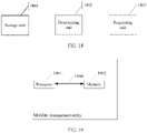
- FIG. 18 is a fourth schematic module diagram of a user plane gateway updating apparatus according to an embodiment of the present invention.
- the apparatus may be the mobility management entity described above, and the apparatus includes a storage unit 1801, a determining unit 1802, and a requesting unit 1803.
- the storage unit 1801 is configured to store a correspondence between each GW-U identifier and a tracking area TA identifier list in advance.
- the determining unit 1802 is configured to: after a tracking area TA in which a user equipment UE is located changes, determine that an original TA in which the UE is located is corresponding to a first TA identifier, and determine that a new TA in which the UE is located is corresponding to a second TA identifier, where a first PDN connection is established between the UE and a first GW-U; and determine, according to the correspondence, that a TA list in which the first TA identifier is is corresponding to a first GW-U identifier, and determine that a TA list in which the second TA identifier is is corresponding to a second GW-U identifier.
- the requesting unit 1803 is configured to: when the first GW-U corresponding to the first GW-U identifier is different from a second GW-U corresponding to the second GW-U identifier, send, to the UE, a request message of re-establishing a PDN connection, where the request message is used to trigger the UE to initiate a second PDN connection, and the second PDN connection is a PDN connection between the UE and the second GW-U.
- the requesting unit 1803 is configured to: send, to the UE, a request message of disconnecting the first PDN connection, where the request message carries a parameter that is used to indicate the UE to establish the second PDN connection.
- FIG. 10 , FIG. 11A , and FIG. 11B are also applicable to the user plane gateway updating apparatus in this embodiment.
- the user plane gateway updating method According to the foregoing detailed description of the user plane gateway updating method, a person skilled in the art can clearly know an implementation method of the user plane gateway updating apparatus in this embodiment. Therefore, for brevity of the specification, details are not described herein.
- FIG. 19 is a second schematic structural diagram of a mobility management entity according to an embodiment of the present invention.
- the mobility management entity may be the mobility management entity described above, and the mobility management entity includes a processor 1901 and a memory 1902.
- the memory 1902 is configured to store a correspondence between each GW-U identifier and a tracking area TA identifier list in advance.
- the processor 1901 is configured to: after a tracking area TA in which a user equipment UE is located changes, determine that an original TA in which the UE is located is corresponding to a first TA identifier, and determine that a new TA in which the UE is located is corresponding to a second TA identifier, where a first PDN connection is established between the UE and a first GW-U; and determine, according to the correspondence, that a TA list in which the first TA identifier is is corresponding to a first GW-U identifier, and determine that a TA list in which the second TA identifier is is corresponding to a second GW-U identifier; and configured to: when the first GW-U corresponding to the first GW-U identifier is different from a second GW-U corresponding to the second GW-U identifier, send, to the UE, a request message of re-establishing a PDN connection, where the request message is used to trigger the UE to
- the processor 1901 is further configured to send, to the UE, a request message of disconnecting the first PDN connection, where the request message carries a parameter that is used to indicate the UE to establish the second PDN connection.
- a bus architecture (represented by using a bus 1900) may include any quantity of interconnected buses and bridges, and the bus 1900 connects together a circuit of one or more processors represented by the processor 1901 and a circuit of a memory represented by the memory 1902.
- the bus 1900 may further connect, for example, a peripheral device or a voltage stabilizer to various other circuits such as a power management circuit.
- the processor 1901 is responsible for managing the bus 1900 and general processing.
- the memory 1902 may be configured to store data that is used when the processor 1901 performs an operation.
- FIG. 10 Various variation manners and specific examples in the foregoing user plane gateway updating method in the embodiments of FIG. 10 , FIG. 11A , and FIG. 11B are also applicable to the mobility management entity in this embodiment.
- the foregoing detailed description of the user plane gateway updating method a person skilled in the art can clearly know an implementation method of the mobility management entity in this embodiment. Therefore, for brevity of the specification, details are not described herein.
- the disclosed system, apparatus, and method may be implemented in other manners.
- the described apparatus embodiment is merely an example.
- the unit or the unit division is merely logical function division and may be other division in actual implementation.
- multiple units or components may be combined or integrated into another system, or some features may be ignored or not performed.
- the displayed or discussed mutual couplings or direct couplings or communication connections may be implemented by using some interfaces.
- the indirect couplings or communication connections between the apparatuses or units may be implemented in electronic, mechanical, or other forms.
- the units described as separate parts may or may not be physically separate, and parts displayed as units may or may not be physical units, may be located in one position, or may be distributed on multiple network units. Some or all of the units may be selected according to actual requirements to achieve the objectives of the solutions of the embodiments.
- functional units in the embodiments of this application may be integrated into one processing unit, or each of the units may exist alone physically, or two or more units are integrated into one unit.
- the integrated unit may be implemented in a form of hardware, or may be implemented in a form of a software functional unit.
- the integrated unit When the integrated unit is implemented in the form of a software functional unit and sold or used as an independent product, the integrated unit may be stored in a computer-readable storage medium. Based on such an understanding, the technical solutions of this application essentially, or the part contributing to the prior art, or all or a part of the technical solutions may be implemented in the form of a software product.
- the computer software product is stored in a storage medium and includes several indicateions for indicateing a computer device (which may be a personal computer, a server, a network device, or the like) or a processor (processor) to perform all or a part of the steps of the methods described in the embodiments of this application.
- the foregoing storage medium includes: any medium that can store program code, such as a USB flash drive, a portable hard disk, a ROM (Read-Only Memory, read-only memory), a RAM (Random Access Memory, random access memory), a magnetic disk, or an optical disc.
- program code such as a USB flash drive, a portable hard disk, a ROM (Read-Only Memory, read-only memory), a RAM (Random Access Memory, random access memory), a magnetic disk, or an optical disc.
- Embodiment 1 A user plane gateway updating method, comprising:
- Embodiment 2 The method according to embodiment 1, wherein the sending, by the GW-C to the MME, a request message of re-establishing a PDN connection comprises: sending, by the GW-C to the MME, the request message of re-establishing a PDN connection, wherein the request message is used to indicate the MME to delete the first PDN connection, and the request message carries a parameter that is used to indicate the UE to establish the second PDN connection.
- Embodiment 3 A user plane gateway updating method, comprising:
- Embodiment 4 The method according to embodiment 2, wherein the sending, by the GW-C to the MME, a request message of re-establishing a PDN connection comprises: sending, by the GW-C to the MME, the request message of re-establishing a PDN connection, wherein the request message is used to indicate the MME to delete the first PDN connection, and the request message carries a parameter that is used to indicate the UE to establish the second PDN connection.
- a user plane gateway updating method comprising:
- Embodiment 6 The method according to embodiment 5, wherein the sending, by the MME to the UE, a request message of re-establishing a PDN connection comprises: sending, by the MME, a request message of disconnecting the first PDN connection, wherein the request message carries a parameter that is used to indicate the UE to establish the second PDN connection.
- Embodiment 7 A user plane gateway updating method, comprising:
- Embodiment 8 The method according to embodiment 7, wherein the sending, by the MME to the UE, a request message of re-establishing a PDN connection comprises: sending, by the MME to the UE, a request message of disconnecting the first PDN connection, wherein the request message carries a parameter that is used to indicate the UE to establish the second PDN connection.
- a user plane gateway updating apparatus comprising:
- Embodiment 10 The apparatus according to embodiment 9, wherein the requesting unit is configured to: send, to the MME, the request message of re-establishing a PDN connection, wherein the request message is used to indicate the MME to delete the first PDN connection, and the request message carries a parameter that is used to indicate the UE to establish the second PDN connection.
- a user plane gateway updating apparatus comprising:
- Embodiment 12 The apparatus according to embodiment 11, wherein the requesting unit is configured to: send, to the MME, the request message of re-establishing a PDN connection, wherein the request message is used to indicate the MME to delete a default bearer of the first PDN connection, and the request message carries a parameter that is used to indicate the UE to establish the second PDN connection.
- a user plane gateway updating apparatus comprising:
- Embodiment 14 The apparatus according to embodiment 13, wherein the requesting unit is configured to: send a request message of disconnecting the first PDN connection, wherein the request message carries a parameter that is used to indicate the UE to establish the second PDN connection.
- a user plane gateway updating apparatus comprising:
- Embodiment 16 The apparatus according to embodiment 15, wherein the requesting unit is configured to: send, to the UE, a request message of disconnecting the first PDN connection, wherein the request message carries a parameter that is used to indicate the UE to establish the second PDN connection.
Landscapes
- Engineering & Computer Science (AREA)
- Computer Networks & Wireless Communication (AREA)
- Signal Processing (AREA)
- Databases & Information Systems (AREA)
- Mobile Radio Communication Systems (AREA)
Priority Applications (1)
| Application Number | Priority Date | Filing Date | Title |
|---|---|---|---|
| EP21195715.4A EP3986082B1 (de) | 2015-08-17 | 2015-08-17 | Verfahren zum aktualisieren von gateways auf benutzerebene, mobilitätsverwaltungsentität, computerlesbares speichermedium und kommunikationssystem |
Applications Claiming Priority (4)
| Application Number | Priority Date | Filing Date | Title |
|---|---|---|---|
| EP19197662.0A EP3697168B1 (de) | 2015-08-17 | 2015-08-17 | Computerlesbare speichermedien und verfahren zum aktualisieren eines gateways auf benutzerebene |
| PCT/CN2015/087256 WO2017028163A1 (zh) | 2015-08-17 | 2015-08-17 | 一种更新用户面网关的方法及装置 |
| EP21195715.4A EP3986082B1 (de) | 2015-08-17 | 2015-08-17 | Verfahren zum aktualisieren von gateways auf benutzerebene, mobilitätsverwaltungsentität, computerlesbares speichermedium und kommunikationssystem |
| EP15901368.9A EP3322237B1 (de) | 2015-08-17 | 2015-08-17 | Verfahren, vorrichtungen und system zur aktualisierung eines gateways auf benutzerebene |
Related Parent Applications (3)
| Application Number | Title | Priority Date | Filing Date |
|---|---|---|---|
| EP15901368.9A Division EP3322237B1 (de) | 2015-08-17 | 2015-08-17 | Verfahren, vorrichtungen und system zur aktualisierung eines gateways auf benutzerebene |
| EP19197662.0A Division EP3697168B1 (de) | 2015-08-17 | 2015-08-17 | Computerlesbare speichermedien und verfahren zum aktualisieren eines gateways auf benutzerebene |
| EP19197662.0A Division-Into EP3697168B1 (de) | 2015-08-17 | 2015-08-17 | Computerlesbare speichermedien und verfahren zum aktualisieren eines gateways auf benutzerebene |
Publications (2)
| Publication Number | Publication Date |
|---|---|
| EP3986082A1 true EP3986082A1 (de) | 2022-04-20 |
| EP3986082B1 EP3986082B1 (de) | 2023-06-28 |
Family
ID=58050498
Family Applications (3)
| Application Number | Title | Priority Date | Filing Date |
|---|---|---|---|
| EP19197662.0A Active EP3697168B1 (de) | 2015-08-17 | 2015-08-17 | Computerlesbare speichermedien und verfahren zum aktualisieren eines gateways auf benutzerebene |
| EP21195715.4A Active EP3986082B1 (de) | 2015-08-17 | 2015-08-17 | Verfahren zum aktualisieren von gateways auf benutzerebene, mobilitätsverwaltungsentität, computerlesbares speichermedium und kommunikationssystem |
| EP15901368.9A Active EP3322237B1 (de) | 2015-08-17 | 2015-08-17 | Verfahren, vorrichtungen und system zur aktualisierung eines gateways auf benutzerebene |
Family Applications Before (1)
| Application Number | Title | Priority Date | Filing Date |
|---|---|---|---|
| EP19197662.0A Active EP3697168B1 (de) | 2015-08-17 | 2015-08-17 | Computerlesbare speichermedien und verfahren zum aktualisieren eines gateways auf benutzerebene |
Family Applications After (1)
| Application Number | Title | Priority Date | Filing Date |
|---|---|---|---|
| EP15901368.9A Active EP3322237B1 (de) | 2015-08-17 | 2015-08-17 | Verfahren, vorrichtungen und system zur aktualisierung eines gateways auf benutzerebene |
Country Status (8)
| Country | Link |
|---|---|
| US (3) | US10484859B2 (de) |
| EP (3) | EP3697168B1 (de) |
| JP (1) | JP6643458B2 (de) |
| KR (1) | KR102071311B1 (de) |
| CN (2) | CN111246527B (de) |
| ES (2) | ES2903206T3 (de) |
| RU (1) | RU2676681C1 (de) |
| WO (1) | WO2017028163A1 (de) |
Families Citing this family (5)
| Publication number | Priority date | Publication date | Assignee | Title |
|---|---|---|---|---|
| CN108377527B (zh) | 2016-11-02 | 2021-02-26 | 华为技术有限公司 | 一种适应灵活部署场景的网络架构 |
| CN108235376B (zh) * | 2016-12-21 | 2020-03-06 | 电信科学技术研究院 | 一种用户面锚点选择方法及装置 |
| CN108512878B (zh) | 2017-02-28 | 2021-01-29 | 华为技术有限公司 | 一种业务管理方法及其装置 |
| EP3725103A1 (de) | 2017-12-15 | 2020-10-21 | IDAC Holdings, Inc. | Verbesserte nf-funktion, mec und 5g-integration |
| US20190314324A1 (en) | 2018-04-13 | 2019-10-17 | The University Of Chicago | Combination of micheliolide derivatives or nanoparticles with ionizing radiation and checkpoint inhibitors for cancer therapy |
Citations (3)
| Publication number | Priority date | Publication date | Assignee | Title |
|---|---|---|---|---|
| WO2014183696A1 (zh) * | 2013-11-29 | 2014-11-20 | 中兴通讯股份有限公司 | 一种路径建立的方法、控制器及移动性管理实体 |
| WO2014183715A1 (zh) * | 2013-11-22 | 2014-11-20 | 中兴通讯股份有限公司 | 一种网关更新信息通知方法及控制器 |
| WO2015100996A1 (zh) * | 2014-01-02 | 2015-07-09 | 中兴通讯股份有限公司 | 一种用户跟踪区的控制方法、控制器及mme |
Family Cites Families (18)
| Publication number | Priority date | Publication date | Assignee | Title |
|---|---|---|---|---|
| KR20070080991A (ko) * | 2006-02-09 | 2007-08-14 | 삼성전자주식회사 | 무선통신 시스템에서 무선 액세스 네트워크와 사용자단게이트웨이와의 데이터 터널 형성 방법 및 그 시스템 |
| WO2008144991A1 (en) * | 2007-05-28 | 2008-12-04 | Huawei Technologies Co., Ltd. | An implementing method and a communication system for saving the address of network anchor point to the network server |
| JP5203780B2 (ja) * | 2008-04-07 | 2013-06-05 | 株式会社日立製作所 | 移動無線通信システムおよびアクセスゲートウェイ |
| IN2011KN03309A (de) * | 2009-01-09 | 2015-07-10 | Ericsson Telefon Ab L M | |
| EP2477441B1 (de) * | 2009-09-18 | 2014-05-21 | NEC Corporation | Kommunikationssystem und Kommunikationssteuerungsverfahren |
| US8358593B2 (en) * | 2009-10-22 | 2013-01-22 | Cisco Technology, Inc. | Systems and methods for selecting serving gateways to service user equipment |
| JP4742171B2 (ja) | 2010-01-06 | 2011-08-10 | 株式会社エヌ・ティ・ティ・ドコモ | 移動通信方法、呼制御ノード、優先度制御ノード及び移動管理ノード |
| CN102918918A (zh) * | 2011-06-03 | 2013-02-06 | 华为技术有限公司 | 业务恢复的处理方法及移动管理网元 |
| US20140126448A1 (en) * | 2011-06-22 | 2014-05-08 | Nec Europe Ltd. | Energy awareness in mobile communication user equipment and networks, including optimizations based on state compression |
| CN102868994A (zh) | 2011-07-08 | 2013-01-09 | 北京三星通信技术研究有限公司 | 一种支持用户设备ue移动性的方法 |
| CN102761965B (zh) * | 2012-04-25 | 2016-03-30 | 中兴通讯股份有限公司 | 跟踪区域更新后保持用户设备业务连续性的方法及装置 |
| EP4336780A3 (de) * | 2012-06-29 | 2024-05-29 | Huawei Technologies Co., Ltd. | Gateway-system, vorrichtung und kommunikationsverfahren |
| US9713057B2 (en) * | 2013-07-26 | 2017-07-18 | Qualcomm Incorporated | Techniques for selected internet protocol traffic offload support at an assisting eNodeB |
| CN104427476B (zh) * | 2013-09-10 | 2019-05-07 | 中兴通讯股份有限公司 | 位置信息上报方法、集群服务处理方法及系统 |
| EP3063988A1 (de) * | 2013-10-30 | 2016-09-07 | Interdigital Patent Holdings, Inc. | Koordinierte paketdatennetzänderung für ausgewählte internetprotokoll-verkehrsentlastung |
| WO2015100638A1 (zh) * | 2013-12-31 | 2015-07-09 | 华为技术有限公司 | 一种业务处理的方法和设备 |
| KR102219415B1 (ko) * | 2014-01-20 | 2021-02-25 | 삼성전자 주식회사 | Lte 망에서 최적 데이터 경로를 위한 mme와 로컬 서버, 이들 간 인터페이스 및 데이터 송수신 방법 |
| WO2016000196A1 (zh) | 2014-06-30 | 2016-01-07 | 华为技术有限公司 | 重建pdn连接的方法、复位中心服务器、移动管理网元和数据网关 |
-
2015
- 2015-08-17 EP EP19197662.0A patent/EP3697168B1/de active Active
- 2015-08-17 KR KR1020187005935A patent/KR102071311B1/ko active Active
- 2015-08-17 EP EP21195715.4A patent/EP3986082B1/de active Active
- 2015-08-17 ES ES19197662T patent/ES2903206T3/es active Active
- 2015-08-17 RU RU2018109377A patent/RU2676681C1/ru active
- 2015-08-17 CN CN202010049418.7A patent/CN111246527B/zh active Active
- 2015-08-17 CN CN201580065482.1A patent/CN107005965B/zh active Active
- 2015-08-17 JP JP2018507698A patent/JP6643458B2/ja active Active
- 2015-08-17 WO PCT/CN2015/087256 patent/WO2017028163A1/zh not_active Ceased
- 2015-08-17 ES ES15901368T patent/ES2766598T3/es active Active
- 2015-08-17 EP EP15901368.9A patent/EP3322237B1/de active Active
-
2018
- 2018-02-14 US US15/897,078 patent/US10484859B2/en active Active
-
2019
- 2019-11-08 US US16/678,050 patent/US11051157B2/en active Active
-
2021
- 2021-06-28 US US17/360,877 patent/US11576030B2/en active Active
Patent Citations (5)
| Publication number | Priority date | Publication date | Assignee | Title |
|---|---|---|---|---|
| WO2014183715A1 (zh) * | 2013-11-22 | 2014-11-20 | 中兴通讯股份有限公司 | 一种网关更新信息通知方法及控制器 |
| EP3073789A1 (de) * | 2013-11-22 | 2016-09-28 | ZTE Corporation | Verfahren zur meldung von gateway-aktualisierungsinformationen und steuerung |
| WO2014183696A1 (zh) * | 2013-11-29 | 2014-11-20 | 中兴通讯股份有限公司 | 一种路径建立的方法、控制器及移动性管理实体 |
| EP3076706A1 (de) * | 2013-11-29 | 2016-10-05 | ZTE Corporation | Wegfestlegungsverfahren, steuerung und mobilitätsverwaltungseinheit |
| WO2015100996A1 (zh) * | 2014-01-02 | 2015-07-09 | 中兴通讯股份有限公司 | 一种用户跟踪区的控制方法、控制器及mme |
Non-Patent Citations (1)
| Title |
|---|
| NICHOLAS KATANEKWA ET AL: "Enhanced gateway selection for optimal routing in a distributed Evolved Packet Core (EPC) network", ELECTRICAL ENGINEERING/ELECTRONICS, COMPUTER, TELECOMMUNICATIONS AND INFORMATION TECHNOLOGY (ECTI-CON), 2013 10TH INTERNATIONAL CONFERENCE ON, IEEE, 15 May 2013 (2013-05-15), pages 1 - 6, XP032435935, ISBN: 978-1-4799-0546-1, DOI: 10.1109/ECTICON.2013.6559549 * |
Also Published As
| Publication number | Publication date |
|---|---|
| WO2017028163A1 (zh) | 2017-02-23 |
| CN111246527A (zh) | 2020-06-05 |
| JP2018531536A (ja) | 2018-10-25 |
| CN107005965B (zh) | 2020-02-14 |
| EP3322237A1 (de) | 2018-05-16 |
| US11051157B2 (en) | 2021-06-29 |
| US20200100094A1 (en) | 2020-03-26 |
| KR20180035871A (ko) | 2018-04-06 |
| US20180176762A1 (en) | 2018-06-21 |
| KR102071311B1 (ko) | 2020-01-30 |
| RU2676681C1 (ru) | 2019-01-10 |
| EP3986082B1 (de) | 2023-06-28 |
| US20210400463A1 (en) | 2021-12-23 |
| ES2903206T3 (es) | 2022-03-31 |
| EP3322237B1 (de) | 2019-11-06 |
| EP3697168B1 (de) | 2021-10-13 |
| CN107005965A (zh) | 2017-08-01 |
| US11576030B2 (en) | 2023-02-07 |
| JP6643458B2 (ja) | 2020-02-12 |
| EP3322237A4 (de) | 2018-07-11 |
| CN111246527B (zh) | 2023-11-17 |
| EP3697168A1 (de) | 2020-08-19 |
| US10484859B2 (en) | 2019-11-19 |
| ES2766598T3 (es) | 2020-06-12 |
Similar Documents
| Publication | Publication Date | Title |
|---|---|---|
| US11576030B2 (en) | User plane gateway updating method and apparatus | |
| US10873886B2 (en) | Mobile edge platform switching method, apparatus, and system | |
| KR102013232B1 (ko) | 게이트웨이 구성 방법 및 게이트웨이 디바이스 | |
| CN108605269B (zh) | 一种会话管理方法及装置 | |
| EP3661270A1 (de) | Verfahren und vorrichtung zur übertragung von informationen | |
| HK1219380A1 (zh) | 恢复移动网络中的分组服务 | |
| US20200084598A1 (en) | Data packet transmission method and device | |
| EP3110187B1 (de) | Verfahren zur shunt-gateway-auswahl und steuergerät | |
| JP2020511876A (ja) | 無線通信方法及び装置 | |
| CN103338487A (zh) | 一种异系统间重选或切换处理方法和设备 | |
| WO2019091077A1 (zh) | 一种触发网络切换的方法及装置、计算机存储介质 | |
| JP2018531536A6 (ja) | ユーザプレーンゲートウェイ更新方法及び装置 | |
| EP2934040B1 (de) | Verfahren zur bereitstellung eines anwendungsdienstes | |
| KR101944647B1 (ko) | 데이터 처리 방법, 장치, 단말기, 이동성 관리 엔티티 및 시스템 | |
| CN108684078B (zh) | 一种更新用户面网关的方法及装置 |
Legal Events
| Date | Code | Title | Description |
|---|---|---|---|
| PUAI | Public reference made under article 153(3) epc to a published international application that has entered the european phase |
Free format text: ORIGINAL CODE: 0009012 |
|
| STAA | Information on the status of an ep patent application or granted ep patent |
Free format text: STATUS: REQUEST FOR EXAMINATION WAS MADE |
|
| 17P | Request for examination filed |
Effective date: 20210909 |
|
| AC | Divisional application: reference to earlier application |
Ref document number: 3322237 Country of ref document: EP Kind code of ref document: P Ref document number: 3697168 Country of ref document: EP Kind code of ref document: P |
|
| AK | Designated contracting states |
Kind code of ref document: A1 Designated state(s): AL AT BE BG CH CY CZ DE DK EE ES FI FR GB GR HR HU IE IS IT LI LT LU LV MC MK MT NL NO PL PT RO RS SE SI SK SM TR |
|
| GRAP | Despatch of communication of intention to grant a patent |
Free format text: ORIGINAL CODE: EPIDOSNIGR1 |
|
| STAA | Information on the status of an ep patent application or granted ep patent |
Free format text: STATUS: GRANT OF PATENT IS INTENDED |
|
| INTG | Intention to grant announced |
Effective date: 20230113 |
|
| GRAS | Grant fee paid |
Free format text: ORIGINAL CODE: EPIDOSNIGR3 |
|
| GRAA | (expected) grant |
Free format text: ORIGINAL CODE: 0009210 |
|
| STAA | Information on the status of an ep patent application or granted ep patent |
Free format text: STATUS: THE PATENT HAS BEEN GRANTED |
|
| P01 | Opt-out of the competence of the unified patent court (upc) registered |
Effective date: 20230514 |
|
| AC | Divisional application: reference to earlier application |
Ref document number: 3322237 Country of ref document: EP Kind code of ref document: P Ref document number: 3697168 Country of ref document: EP Kind code of ref document: P |
|
| AK | Designated contracting states |
Kind code of ref document: B1 Designated state(s): AL AT BE BG CH CY CZ DE DK EE ES FI FR GB GR HR HU IE IS IT LI LT LU LV MC MK MT NL NO PL PT RO RS SE SI SK SM TR |
|
| REG | Reference to a national code |
Ref country code: CH Ref legal event code: EP |
|
| REG | Reference to a national code |
Ref country code: AT Ref legal event code: REF Ref document number: 1583874 Country of ref document: AT Kind code of ref document: T Effective date: 20230715 |
|
| REG | Reference to a national code |
Ref country code: IE Ref legal event code: FG4D |
|
| REG | Reference to a national code |
Ref country code: DE Ref legal event code: R096 Ref document number: 602015084408 Country of ref document: DE |
|
| REG | Reference to a national code |
Ref country code: LT Ref legal event code: MG9D |
|
| PG25 | Lapsed in a contracting state [announced via postgrant information from national office to epo] |
Ref country code: SE Free format text: LAPSE BECAUSE OF FAILURE TO SUBMIT A TRANSLATION OF THE DESCRIPTION OR TO PAY THE FEE WITHIN THE PRESCRIBED TIME-LIMIT Effective date: 20230628 Ref country code: NO Free format text: LAPSE BECAUSE OF FAILURE TO SUBMIT A TRANSLATION OF THE DESCRIPTION OR TO PAY THE FEE WITHIN THE PRESCRIBED TIME-LIMIT Effective date: 20230928 |
|
| REG | Reference to a national code |
Ref country code: NL Ref legal event code: MP Effective date: 20230628 |
|
| REG | Reference to a national code |
Ref country code: AT Ref legal event code: MK05 Ref document number: 1583874 Country of ref document: AT Kind code of ref document: T Effective date: 20230628 |
|
| PG25 | Lapsed in a contracting state [announced via postgrant information from national office to epo] |
Ref country code: RS Free format text: LAPSE BECAUSE OF FAILURE TO SUBMIT A TRANSLATION OF THE DESCRIPTION OR TO PAY THE FEE WITHIN THE PRESCRIBED TIME-LIMIT Effective date: 20230628 Ref country code: NL Free format text: LAPSE BECAUSE OF FAILURE TO SUBMIT A TRANSLATION OF THE DESCRIPTION OR TO PAY THE FEE WITHIN THE PRESCRIBED TIME-LIMIT Effective date: 20230628 Ref country code: LV Free format text: LAPSE BECAUSE OF FAILURE TO SUBMIT A TRANSLATION OF THE DESCRIPTION OR TO PAY THE FEE WITHIN THE PRESCRIBED TIME-LIMIT Effective date: 20230628 Ref country code: LT Free format text: LAPSE BECAUSE OF FAILURE TO SUBMIT A TRANSLATION OF THE DESCRIPTION OR TO PAY THE FEE WITHIN THE PRESCRIBED TIME-LIMIT Effective date: 20230628 Ref country code: HR Free format text: LAPSE BECAUSE OF FAILURE TO SUBMIT A TRANSLATION OF THE DESCRIPTION OR TO PAY THE FEE WITHIN THE PRESCRIBED TIME-LIMIT Effective date: 20230628 Ref country code: GR Free format text: LAPSE BECAUSE OF FAILURE TO SUBMIT A TRANSLATION OF THE DESCRIPTION OR TO PAY THE FEE WITHIN THE PRESCRIBED TIME-LIMIT Effective date: 20230929 |
|
| PG25 | Lapsed in a contracting state [announced via postgrant information from national office to epo] |
Ref country code: FI Free format text: LAPSE BECAUSE OF FAILURE TO SUBMIT A TRANSLATION OF THE DESCRIPTION OR TO PAY THE FEE WITHIN THE PRESCRIBED TIME-LIMIT Effective date: 20230628 |
|
| PG25 | Lapsed in a contracting state [announced via postgrant information from national office to epo] |
Ref country code: SK Free format text: LAPSE BECAUSE OF FAILURE TO SUBMIT A TRANSLATION OF THE DESCRIPTION OR TO PAY THE FEE WITHIN THE PRESCRIBED TIME-LIMIT Effective date: 20230628 |
|
| PG25 | Lapsed in a contracting state [announced via postgrant information from national office to epo] |
Ref country code: ES Free format text: LAPSE BECAUSE OF FAILURE TO SUBMIT A TRANSLATION OF THE DESCRIPTION OR TO PAY THE FEE WITHIN THE PRESCRIBED TIME-LIMIT Effective date: 20230628 |
|
| PG25 | Lapsed in a contracting state [announced via postgrant information from national office to epo] |
Ref country code: IS Free format text: LAPSE BECAUSE OF FAILURE TO SUBMIT A TRANSLATION OF THE DESCRIPTION OR TO PAY THE FEE WITHIN THE PRESCRIBED TIME-LIMIT Effective date: 20231028 |
|
| PG25 | Lapsed in a contracting state [announced via postgrant information from national office to epo] |
Ref country code: SM Free format text: LAPSE BECAUSE OF FAILURE TO SUBMIT A TRANSLATION OF THE DESCRIPTION OR TO PAY THE FEE WITHIN THE PRESCRIBED TIME-LIMIT Effective date: 20230628 Ref country code: SK Free format text: LAPSE BECAUSE OF FAILURE TO SUBMIT A TRANSLATION OF THE DESCRIPTION OR TO PAY THE FEE WITHIN THE PRESCRIBED TIME-LIMIT Effective date: 20230628 Ref country code: RO Free format text: LAPSE BECAUSE OF FAILURE TO SUBMIT A TRANSLATION OF THE DESCRIPTION OR TO PAY THE FEE WITHIN THE PRESCRIBED TIME-LIMIT Effective date: 20230628 Ref country code: PT Free format text: LAPSE BECAUSE OF FAILURE TO SUBMIT A TRANSLATION OF THE DESCRIPTION OR TO PAY THE FEE WITHIN THE PRESCRIBED TIME-LIMIT Effective date: 20231030 Ref country code: IS Free format text: LAPSE BECAUSE OF FAILURE TO SUBMIT A TRANSLATION OF THE DESCRIPTION OR TO PAY THE FEE WITHIN THE PRESCRIBED TIME-LIMIT Effective date: 20231028 Ref country code: ES Free format text: LAPSE BECAUSE OF FAILURE TO SUBMIT A TRANSLATION OF THE DESCRIPTION OR TO PAY THE FEE WITHIN THE PRESCRIBED TIME-LIMIT Effective date: 20230628 Ref country code: EE Free format text: LAPSE BECAUSE OF FAILURE TO SUBMIT A TRANSLATION OF THE DESCRIPTION OR TO PAY THE FEE WITHIN THE PRESCRIBED TIME-LIMIT Effective date: 20230628 Ref country code: CZ Free format text: LAPSE BECAUSE OF FAILURE TO SUBMIT A TRANSLATION OF THE DESCRIPTION OR TO PAY THE FEE WITHIN THE PRESCRIBED TIME-LIMIT Effective date: 20230628 Ref country code: AT Free format text: LAPSE BECAUSE OF FAILURE TO SUBMIT A TRANSLATION OF THE DESCRIPTION OR TO PAY THE FEE WITHIN THE PRESCRIBED TIME-LIMIT Effective date: 20230628 |
|
| PG25 | Lapsed in a contracting state [announced via postgrant information from national office to epo] |
Ref country code: PL Free format text: LAPSE BECAUSE OF FAILURE TO SUBMIT A TRANSLATION OF THE DESCRIPTION OR TO PAY THE FEE WITHIN THE PRESCRIBED TIME-LIMIT Effective date: 20230628 |
|
| PG25 | Lapsed in a contracting state [announced via postgrant information from national office to epo] |
Ref country code: MC Free format text: LAPSE BECAUSE OF FAILURE TO SUBMIT A TRANSLATION OF THE DESCRIPTION OR TO PAY THE FEE WITHIN THE PRESCRIBED TIME-LIMIT Effective date: 20230628 |
|
| REG | Reference to a national code |
Ref country code: CH Ref legal event code: PL |
|
| PG25 | Lapsed in a contracting state [announced via postgrant information from national office to epo] |
Ref country code: MC Free format text: LAPSE BECAUSE OF FAILURE TO SUBMIT A TRANSLATION OF THE DESCRIPTION OR TO PAY THE FEE WITHIN THE PRESCRIBED TIME-LIMIT Effective date: 20230628 |
|
| REG | Reference to a national code |
Ref country code: DE Ref legal event code: R097 Ref document number: 602015084408 Country of ref document: DE |
|
| PG25 | Lapsed in a contracting state [announced via postgrant information from national office to epo] |
Ref country code: LU Free format text: LAPSE BECAUSE OF NON-PAYMENT OF DUE FEES Effective date: 20230817 |
|
| PG25 | Lapsed in a contracting state [announced via postgrant information from national office to epo] |
Ref country code: LU Free format text: LAPSE BECAUSE OF NON-PAYMENT OF DUE FEES Effective date: 20230817 Ref country code: DK Free format text: LAPSE BECAUSE OF FAILURE TO SUBMIT A TRANSLATION OF THE DESCRIPTION OR TO PAY THE FEE WITHIN THE PRESCRIBED TIME-LIMIT Effective date: 20230628 Ref country code: CH Free format text: LAPSE BECAUSE OF NON-PAYMENT OF DUE FEES Effective date: 20230831 |
|
| PLBE | No opposition filed within time limit |
Free format text: ORIGINAL CODE: 0009261 |
|
| STAA | Information on the status of an ep patent application or granted ep patent |
Free format text: STATUS: NO OPPOSITION FILED WITHIN TIME LIMIT |
|
| REG | Reference to a national code |
Ref country code: BE Ref legal event code: MM Effective date: 20230831 |
|
| REG | Reference to a national code |
Ref country code: IE Ref legal event code: MM4A |
|
| PG25 | Lapsed in a contracting state [announced via postgrant information from national office to epo] |
Ref country code: IT Free format text: LAPSE BECAUSE OF FAILURE TO SUBMIT A TRANSLATION OF THE DESCRIPTION OR TO PAY THE FEE WITHIN THE PRESCRIBED TIME-LIMIT Effective date: 20230628 |
|
| 26N | No opposition filed |
Effective date: 20240402 |
|
| PG25 | Lapsed in a contracting state [announced via postgrant information from national office to epo] |
Ref country code: IE Free format text: LAPSE BECAUSE OF NON-PAYMENT OF DUE FEES Effective date: 20230817 |
|
| PG25 | Lapsed in a contracting state [announced via postgrant information from national office to epo] |
Ref country code: IE Free format text: LAPSE BECAUSE OF NON-PAYMENT OF DUE FEES Effective date: 20230817 Ref country code: SI Free format text: LAPSE BECAUSE OF FAILURE TO SUBMIT A TRANSLATION OF THE DESCRIPTION OR TO PAY THE FEE WITHIN THE PRESCRIBED TIME-LIMIT Effective date: 20230628 |
|
| PG25 | Lapsed in a contracting state [announced via postgrant information from national office to epo] |
Ref country code: BE Free format text: LAPSE BECAUSE OF NON-PAYMENT OF DUE FEES Effective date: 20230831 |
|
| PG25 | Lapsed in a contracting state [announced via postgrant information from national office to epo] |
Ref country code: BG Free format text: LAPSE BECAUSE OF FAILURE TO SUBMIT A TRANSLATION OF THE DESCRIPTION OR TO PAY THE FEE WITHIN THE PRESCRIBED TIME-LIMIT Effective date: 20230628 |
|
| PG25 | Lapsed in a contracting state [announced via postgrant information from national office to epo] |
Ref country code: BG Free format text: LAPSE BECAUSE OF FAILURE TO SUBMIT A TRANSLATION OF THE DESCRIPTION OR TO PAY THE FEE WITHIN THE PRESCRIBED TIME-LIMIT Effective date: 20230628 |
|
| PG25 | Lapsed in a contracting state [announced via postgrant information from national office to epo] |
Ref country code: CY Free format text: LAPSE BECAUSE OF FAILURE TO SUBMIT A TRANSLATION OF THE DESCRIPTION OR TO PAY THE FEE WITHIN THE PRESCRIBED TIME-LIMIT; INVALID AB INITIO Effective date: 20150817 |
|
| PG25 | Lapsed in a contracting state [announced via postgrant information from national office to epo] |
Ref country code: HU Free format text: LAPSE BECAUSE OF FAILURE TO SUBMIT A TRANSLATION OF THE DESCRIPTION OR TO PAY THE FEE WITHIN THE PRESCRIBED TIME-LIMIT; INVALID AB INITIO Effective date: 20150817 |
|
| PGFP | Annual fee paid to national office [announced via postgrant information from national office to epo] |
Ref country code: DE Payment date: 20250702 Year of fee payment: 11 |
|
| PGFP | Annual fee paid to national office [announced via postgrant information from national office to epo] |
Ref country code: GB Payment date: 20250703 Year of fee payment: 11 |
|
| PGFP | Annual fee paid to national office [announced via postgrant information from national office to epo] |
Ref country code: FR Payment date: 20250703 Year of fee payment: 11 |
|
| PG25 | Lapsed in a contracting state [announced via postgrant information from national office to epo] |
Ref country code: TR Free format text: LAPSE BECAUSE OF FAILURE TO SUBMIT A TRANSLATION OF THE DESCRIPTION OR TO PAY THE FEE WITHIN THE PRESCRIBED TIME-LIMIT Effective date: 20230628 |