EP3986097B1 - Remote-i/o-system - Google Patents
Remote-i/o-system Download PDFInfo
- Publication number
- EP3986097B1 EP3986097B1 EP20202251.3A EP20202251A EP3986097B1 EP 3986097 B1 EP3986097 B1 EP 3986097B1 EP 20202251 A EP20202251 A EP 20202251A EP 3986097 B1 EP3986097 B1 EP 3986097B1
- Authority
- EP
- European Patent Office
- Prior art keywords
- remote
- module
- cover
- housing
- base body
- Prior art date
- Legal status (The legal status is an assumption and is not a legal conclusion. Google has not performed a legal analysis and makes no representation as to the accuracy of the status listed.)
- Active
Links
Images


Classifications
-
- H—ELECTRICITY
- H05—ELECTRIC TECHNIQUES NOT OTHERWISE PROVIDED FOR
- H05K—PRINTED CIRCUITS; CASINGS OR CONSTRUCTIONAL DETAILS OF ELECTRIC APPARATUS; MANUFACTURE OF ASSEMBLAGES OF ELECTRICAL COMPONENTS
- H05K5/00—Casings, cabinets or drawers for electric apparatus
- H05K5/0026—Casings, cabinets or drawers for electric apparatus provided with connectors and printed circuit boards [PCB], e.g. automotive electronic control units
- H05K5/0047—Casings, cabinets or drawers for electric apparatus provided with connectors and printed circuit boards [PCB], e.g. automotive electronic control units having a two-part housing enclosing a PCB
- H05K5/0056—Casings, cabinets or drawers for electric apparatus provided with connectors and printed circuit boards [PCB], e.g. automotive electronic control units having a two-part housing enclosing a PCB characterized by features for protecting electronic components against vibration and moisture, e.g. potting, holders for relatively large capacitors
Definitions
- the invention relates to a remote I/O system according to the preamble of claim 1.
- a remote I/O system for use in a potentially explosive area includes a remote I/O module (remote input/output module).
- the remote I/O module is designed to securely connect sensors and actuators to a control system, such as a computer.
- the remote I/O module can be arranged in a decentralized manner and can transmit process data from binary and analog sensors and actuators from the potentially explosive area to the control system, for example via a bus interface of the remote I/O module. Process data can also be transmitted from the control system to the potentially explosive area via the remote I/O module. Due to the reduced wiring effort thanks to the remote I/O module, not only cables but also time, money and work can be saved.
- the remote I/O module To ensure that the remote I/O module cannot serve as an ignition source for an explosion, it is designed in such a way that no sparks can be generated despite the cables connected by the remote I/O module and that the remote I/O module does not exceed a specified temperature value.
- the remote I/O module is arranged in a housing.
- the housing surrounds the remote I/O module on all sides so that it is completely enclosed in the housing.
- the housing can also shield the remote I/O module from gases, particularly flammable gases.
- Such housings enclose a large volume that is many times larger than the installation space of the remote I/O module. As a result, the entire remote I/O system requires a large amount of installation space.
- the housing is typically a control cabinet.
- the housing has a box and a cover.
- the cover In order to be able to open the cover and check the status of the remote I/O module using a display on the remote I/O module, it must first be ensured that no flammable gases can penetrate the remote I/O module when the housing is opened. To do this, the gas concentration in the ambient air must be determined in a so-called clearance measurement.
- a radio for use in an area at risk of explosion, the base body of which has electrical contacts and which is arranged in a housing. Cables are led from the electrical contacts of the base body through a cover of the housing.
- the housing encloses a large installation volume.
- the invention is based on the object of developing a generic remote I/O system in such a way that the remote I/O system requires a small installation space.
- the invention provides that the cover of the housing rests directly on the base body of the remote I/O module. This means that there is no gap between the remote I/O module and the cover. This means that the remote I/O system can be designed so that there is no free space between the cover and the remote I/O module. This saves installation space.
- the remote I/O system can be manufactured in a space- and material-saving manner.
- the box of the remote I/O system is advantageously formed by the base body of the remote I/O module.
- the box and the base body are expediently integral together.
- the box and the base body are made of the same material. This means that the box of the remote I/O system and the base body of the remote I/O module are the same component. This saves material and simplifies production.
- the remote I/O system is smaller.
- the remote I/O system is therefore more compact and stable.
- the remote I/O module includes the housing. No additional or separate protective housing is required.
- the remote I/O module can be installed directly in the potentially explosive area.
- the housing expediently has at least one through-opening for the electrical cable to pass through. This allows an electrical cable to be easily connected to the at least one connection through the through-opening.
- the through-opening is a cable gland for the tight introduction of cables from the outside of the housing to the inside of the housing.
- the cable gland is advantageously a tank thread. This allows cables to be introduced into the inside of the housing, and the housing is still sealed to the outside.
- the through-opening is advantageously formed in the base body. This allows a cable guided through the through-opening to be easily connected to the at least one connection. This allows the remote I/O system to be designed flat.
- the through-opening is formed in the cover. If a remote I/O module is defective, it is sufficient to simply replace the base body of the remote I/O module.
- the cable can remain fed through the cover, and the cover can be placed on a new base body together with the cable. This saves time and material.
- the at least one connection advantageously has a clamp or snap connection. This can be released when the base body is replaced. This makes it easy to release and reconnect the at least one cable to the base body of the remote I/O module. It is practical to connect several cables to the base body at the same time using a clamp or snap connection.
- the base body has a receiving space for the connection.
- the receiving space is expediently delimited by a receiving space wall which runs closed around an axis.
- the axis extends in particular from a base of the receiving space to an opening in the receiving space.
- the connection is thus protected in the receiving space.
- a cover can easily cover the receiving space.
- the remote I/O system expediently has an outer wall facing the environment, which is simultaneously the outer wall of the box and the base body.
- the outer wall is advantageously part of the receiving space wall. This means that the remote I/O system can be designed, for example, so that the through-opening leads through the receiving space wall directly into the receiving space. This makes it easier to connect the cable to at least one connection.
- the receiving space has an opening.
- the opening is expediently closed by the cover.
- the opening is advantageously sealed by the cover to prevent the passage of gases, in particular flammable gases. This reliably prevents gases from penetrating the connections.
- the remote I/O module has a display that is formed on the base body and is not covered by the cover. This means that the connections can be protected by the cover, and at the same time the status of the remote I/O module can be checked by looking at the display. Opening the housing is not necessary for this.
- the display is advantageously an illuminated display.
- At least one electrical circuit is expediently arranged in the base body of the remote I/O module.
- the electrical circuit is in particular a circuit board.
- the electrical circuit is advantageously cast into the base body using an electrically insulating material.
- the electrically insulating material is expediently a synthetic resin.
- the base body consists at least partially of aluminum.
- the lid is expediently made at least partially of aluminum.
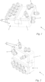
- Fig. 1 shows a remote I/O system 1.
- the remote VO system 1 is also called a remote input/output system.
- Another name for the remote I/O system 1 is called a decentralized input/output system.
- the remote I/O system 1 includes a remote I/O module 2.
- the remote I/O module 2 is also called a remote input/output module or a decentralized input/output module.
- the remote I/O module 2 has a bus interface (not shown). Electrical signals can be transmitted via the bus interface of the remote I/O module 2. Sensors and/or actuators can be connected to a control system (not shown) using the remote I/O module 2. The sensors and/or actuators can be digital or analog sensors and/or actuators.
- the control system is, for example, a control unit or a computer. In the exemplary embodiment, the control system is a programmable logic controller. Typically, process data from the sensor and/or the actuator is transmitted to the control system via the remote I/O module 2, or process data is transmitted from the control system to the sensor and/or the actuator via the remote I/O module 2.
- the remote I/O module 2 is designed for use in an explosion-proof area.
- the explosion-proof area is also known as a potentially explosive zone.
- the remote I/O module 2 is designed in such a way that it does not represent an ignition source for an explosive substance. No sparks are generated when the remote I/O module 2 is in operation.
- the remote I/O module 2 is designed in such a way that it does not exceed a specified limit temperature.
- the remote I/O module 2 is designed for use in zones 1 and 21 as defined in Directive 2014/34/EU.
- the remote I/O system 1 is designed for use in zones 1 and 21 as defined in Directive 2014/34/EU.
- the remote I/O module 2 is designed for an area in which an explosive atmosphere as a mixture of air and flammable gases, vapors or mists can occasionally form during normal operation. Furthermore, the remote I/O module 2 is designed for an area in which an explosive atmosphere in the form of a cloud of combustible dust in the air can occasionally form during normal operation.
- the remote I/O system 1 is also designed for these two areas.
- the remote I/O system 1 can be arranged decentrally in a potentially explosive area.
- a sensor and/or an actuator can be arranged in the potentially explosive area and is connected via the remote I/O system 1 to a control system that is located outside the potentially explosive area. This means that the sensor and/or actuator can be safely controlled and/or monitored from the control system.
- the bus interface of the remote I/O module 2 ensures that the wiring effort is reduced.
- the remote I/O module 2 comprises a base body 3. At least one connection 4 is arranged on the base body 3, as shown in Fig. 5 shown. A line 5 can be connected to the connection 4. The line 5 connects the remote I/O module 2 to an actuator and/or a sensor (not shown). A control connection 18 is arranged on the base body 3. A control line 19 can be connected to the control connection 18. The control line 19 connects the remote I/O module 2 to the control system.
- the control line 19 has a plug (not shown) at its end facing the remote I/O module 2. The control line is plugged into the control connection 19 using the plug.
- the remote I/O system 1 comprises a housing 6 ( Figures 1 and 2 ).
- the housing 6 has a box 7 and a cover 8.
- the connection 4 is arranged in the housing 6.
- the housing 6 surrounds the connection 4 on all sides.
- the housing 6 completely encloses the connection 4.
- the connection 4 is arranged in the box 7.
- the housing 6 is sealed against gases, in particular against easily flammable gases.
- the remote I/O system 1 is designed in accordance with DIN EN 60529 with IP protection class (International Protection or Ingress Protection) IP67. Accordingly, the housing 6 is dust-tight. The housing 6 offers complete protection against contact for the components arranged in the housing 6. The housing 6 offers protection against temporary submersion.
- IP protection class International Protection or Ingress Protection
- the cover 8 of the housing 6 lies directly on the base body 2 of the remote I/O module 2. There is no gap between the base body 2 and the cover 8.
- the cover 8 lies flat against the base body 3.
- the base body 2 has a receiving space 12 for the connection 4 ( Fig. 5 ).
- the cover 8 completely covers the receiving space 12 for the connection 4.
- the cover 8 seals the receiving space 12 tightly against gases.
- the receiving space 12 offers space for the end of the cable 5 which is led through the through-opening 9.
- the individual wires of the cable 5 are connected to the connection 4 in the receiving space 12.
- the box 7 of the housing 6 of the remote I/O system 1 is formed by the base body 3 of the remote I/O module 2.
- the box 7 and the base body 3 are formed in one piece.
- the box 7 and the base body 3 are the same component.
- the box 7 and the base body 3 are formed from the same material.
- the base body 3 is made of aluminum.
- the surface of the base body 3 is formed by a protective layer.
- the protective layer protects against corrosion and mechanical damage to the base body 3.
- the protective layer is an electrochemically deposited metal layer.
- the protective layer is applied by galvanization.
- the protective layer is produced by anodizing the aluminum.
- the base body 3 can also consist at least partially of zinc.
- the base body 3 can consist at least partially of plastic.
- the base body 3 is then advantageously produced using an injection molding process.
- a protective surface layer can be provided on the surface of the base body 3.
- One possibility for applying such a protective layer is also available for base bodies made of zinc by galvanization.
- the receiving space 12 is delimited by a receiving space wall 13.
- the receiving space 12 has a floor 20.
- the floor 20 is separated from the The receiving space 12 is limited by the receiving space wall 13.
- the receiving space 12 has an opening 15.
- the opening 15 is opposite the base 20.
- the receiving space wall 13 extends between the opening 15 and the base 20.
- An axis 50 runs through the receiving space 13.
- the axis 50 runs along an opening direction 49.
- the opening direction 49 points from the base 20 to the opening 15.
- the axis 50 penetrates the base 20.
- the axis 50 is at a distance from the receiving space wall 13.
- the receiving space wall 13 encloses the axis 50.
- the receiving space wall 13 runs closed around the axis 50.
- the remote I/O system 1 has an outer wall 14.
- the outer wall 14 delimits the remote I/O system 1 with respect to the outer side 10 of the remote I/O system 1 ( Fig. 5 ).
- the outer wall 14 is the outer wall of the box 7.
- the outer wall 14 is the outer wall of the base body 3.
- the box 7 and the base body 3 have the common outer wall 14.
- a part of the outer wall 14 is part of the receiving space wall 13 of the receiving space 14.
- the housing 6 has a through-opening 9 for the electrical cable 9 to pass through.
- the cable 5 is guided through the through-opening 9 from the outside 10 to the inside 11 of the housing 6.
- the through-opening 9 is a cable screw connection.
- the cable screw connection enables the cable 5 to be introduced tightly from the outside 10 to the inside 11.
- the cable screw connection seals the housing 6 against gases.
- the cable screw connection is a tank thread.
- a through-opening 9 is arranged in the embodiment.
- a through-opening is arranged only in the cover 8.
- the base body 3 is then free of through-openings.
- a through-opening is arranged.
- the cover 8 is then free of through-openings.
- connection 4 is a terminal.
- the terminal can accommodate wires in several receptacles.
- the receptacles each have a receptacle opening 26.
- the connection 4 is detachably connected to the base body 3. This allows the line 5 to be conveniently connected to the connection 4 when the connection 4 is released.
- the connection 4 is then reconnected to the base body 3.
- the terminal is connected to the base body 3 of the remote I/O module 2 via a clamp connection.
- the terminal is connected to the base body 3 via a snap-in connection.
- the terminal has an electrical contact (not shown) at its end facing away from the receptacle openings 26.
- the electrical contact contacts an electrical circuit 17 ( Fig. 7 ) of the remote I/O module 2.
- the combination of the terminal receptacles and the electrical contacts creates digital inputs and outputs of the remote I/O module 2.
- the digital inputs are designed according to the Namur standard.
- the digital outputs are designed for a voltage of 24V.
- Analog sensors and/or actuators can be connected to the remote EO module 2 via a current loop interface.
- the loop current can be from 4 mA to 20 mA.
- a compartment 21 is formed inside the base body 3.
- the compartment 21 serves to accommodate the electrical circuit 17.
- the electrical circuit 17 is a circuit board.
- the electrical circuit 17 is embedded in an electrically insulating material.
- the electrically insulating material is synthetic resin.
- the electrical circuit 17 is connected to the electrically insulating material cast into the base body 3.
- the compartment 21 is filled with the electrically insulating material.
- the terminal connects the line 5 with the electrical circuit 17.
- the base body has a second receiving space 22.
- the second receiving space 22 serves to receive the control connection 18.
- the second receiving space 22 is covered by a cover 8, analogous to the receiving space 12.
- the control connection 18 connects the control line 19 to the electrical circuit 17.
- the control line 19 is guided through a second feedthrough 23 from the inside 11 to the outside 10.
- the second feedthrough 23 is designed analogously to the feedthrough 9. It can also be installed in the cover 8 ( Fig. 6 ) as well as in the base body 3 ( Fig. 5 ). It can also be provided either only in the cover or only in the base body.
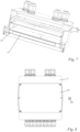
- the in Fig. 6 The cover 8 shown is made of aluminum.
- the surface of the cover 8 is formed by a protective layer.
- the protective layer protects against corrosion and mechanical damage to the cover 8.
- the protective layer is an electrochemically deposited metal layer.
- the protective layer is applied by galvanization.
- the protective layer is produced by anodizing the aluminum.
- base body 3 has a recess for receiving a projection of the cover 8.
- the recess extends in the direction opposite to the opening direction 49.
- the recess runs closed around the axis 50.
- the recess is arranged in a front side 24 of the receiving space wall 13.
- the receiving space wall 13 runs closed around the axis 50.
- the projection of the cover 8 expediently runs closed around the axis 50.
- the projection of the cover 8 is designed to correspond to the recess of the base body 3.
- the recess can also be referred to as a groove and the projection as a tongue.
- the interaction of the projection and the recess enables the cover 8 to be easily positioned on the base body 3.
- the interaction of the projection and the recess ensures a tight connection between the cover 8 and the base body 3. It can also be provided that a seal is arranged between the projection and the recess.
- the projection can also be provided on the base body 3 and the recess in the cover 8.
- the cover 8 is fastened to the base body 3 by means of at least one fastening means (not shown).
- the fastening means is formed by a screw, a hole in the cover 8 and a thread in the base body 3.
- the cover 8 is fastened to the base body 3 with several screws.
- the opening 15 of the receiving space 12 is formed in one plane.
- the receiving space 12 is open in the opening direction 49.
- the receiving space 12 is open in more than one direction, so that several planes can be applied to the opening 15.
- the cover 8 is then formed to correspond to the geometry of the opening 15.
- the shape of the cover 8 in cross section can be essentially L-shaped.
- the remote EO module 2 has a display 16.
- the display 16 is a light display.
- the display 16 is formed by LEDs. It can be provided that the LEDs are used in the form of a light bar.
- the display 16 is attached to the inside 11 of the base body 3 and is visible from the outside 10 through corresponding display openings in the base body 3.
- the display 16 is arranged on the base body 3 of the remote I/O module 2.
- the display 16 is not covered by the cover 8. The display 16 is visible from the outside 10 even when the housing 6 is closed.
- the base body 3 is closed on its underside by a cover 25.
- the cover 25 is attached to the base body 3 by means of screws.
- the cover 25 can be removed from the base body 3 in the direction opposite to the opening direction 49. This allows access to the electrical circuit 17.
- the remote I/O module 2 includes a current measuring device for measuring the current flowing through individual channels.
- the remote I/O module 2 also has a voltage measuring device for detecting over- and/or under-voltages.
- the remote I/O module 2 includes a temperature sensor that measures the temperature of the remote I/O module 2.
- the evaluation of these measurement data can be carried out by the control system.
- a control device is provided for this purpose.
- the control device is part of the remote I/O module 2.
- the remote I/O module 2 is switched off by the control device.
- the control device of the remote I/O module 2 makes decisions based on learned processes. For this purpose, an AI algorithm that represents artificial intelligence is stored in the control device.
- the remote I/O module 2 can operate independently via the control device.
- the remote I/O module 2 can learn the system process independently using the control device's AI algorithm.
- the data supplied to the remote I/O module 2 from the connected sensors and/or actuators and the measurement data from the remote I/O module 2 are recorded and evaluated by the AI algorithm over a longer period of time.
- An artificial neural network is formed in the control device, which uses deep learning to record structures in the collected data and makes decisions based on this. In particular, any anomalies that occur can be reliably classified as critical or non-critical. This means that the data transfer from the remote I/O module 2 to the control system can be reduced.
- the data does not have to be constantly forwarded or queried, but is pre-filtered by the control device.
- control device completely replaces the control system.
- the control device then controls the remote I/O module 2 completely independently.
- the individual control steps are controlled by the AI algorithm.
Landscapes
- Engineering & Computer Science (AREA)
- Microelectronics & Electronic Packaging (AREA)
- Casings For Electric Apparatus (AREA)
Description
- Die Erfindung betrifft ein Remote-I/O-System nach dem Oberbegriff des Anspruchs 1.
- Ein Remote-I/O-System (Remote-Input/Output-System) zum Einsatz in einem explosionsgefährdeten Bereich umfasst ein Remote-I/O-Modul (Remote-Input/Output-Modul). Das Remote-I/O-Modul ist zur sicheren Verbindung von Sensoren und Aktoren mit einem Leitsystem, beispielsweise einem Computer vorgesehen. Das Remote-I/O-Modul kann dezentral angeordnet werden und Prozessdaten von binären und analogen Sensoren und Aktoren beispielsweise über eine Busschnittstelle des Remote-I/O-Moduls aus dem explosionsgefährdeten Bereich an das Leitsystem übertragen. Genauso können Prozessdaten über das Remote-I/O-Modul vom Leitsystem in den explosionsgefährdeten Bereich übertragen werden. Aufgrund des durch das Remote-I/O-Modul reduzierten Verdrahtungsaufwands können nicht nur Kabel, sondern auch Zeit, Geld und Arbeitsaufwand eingespart werden. Damit das Remote-I/O-Modul nicht als Zündquelle für eine Explosion dienen kann, ist es so ausgelegt, dass trotz der durch das Remote-I/O-Modul miteinander verbundenen Kabel keine Funken entstehen können und das Remote-I/O-Modul einen vorgegebenen Temperaturwert nicht überschreitet. Zum Schutz vor Staub, insbesondere vor entzündlichem Staub, und mechanischen Einwirkungen ist das Remote-I/O-Modul in einem Gehäuse angeordnet. Das Gehäuse umgibt das Remote-I/O-Modul allseitig, so dass es vollständig in dem Gehäuse eingeschlossen ist. Das Gehäuse kann das Remote-I/O-Modul auch vor Gasen, insbesondere vor entzündlichen Gasen abschirmen. Derartige Gehäuse schließen ein großes Volumen ein, das um ein Vielfaches größer ist als das Bauraumvolumen des Remote-I/O-Moduls. In der Folge benötigt das gesamte Remote-I/O-System einen großen Bauraum. Typischerweise ist das Gehäuse ein Schaltschrank. Das Gehäuse weist einen Kasten und einen Deckel auf. Um den Deckel öffnen zu können und den Zustand des Remote-I/O-Moduls anhand von einer Anzeige des Remote-I/O-Moduls überprüfen zu können, muss zunächst sichergestellt werden, dass beim Öffnen des Gehäuses keine entzündlichen Gase zum Remote-I/O-Modul vordringen können. Hierzu muss die Gaskonzentration der Umgebungsluft in einer sogenannten Freimessung bestimmt werden.
- Aus der
JP 2005-348542 A - Der Erfindung liegt die Aufgabe zugrunde, ein gattungsgemäßes Remote-I/O-System derart weiterzubilden, dass das Remote-I/O-System einen kleinen Bauraum benötigt.
- Diese Aufgabe wird durch ein Remote-I/O-System mit den Merkmalen des Anspruchs 1 gelöst.
- Die Erfindung sieht vor, dass der Deckel des Gehäuses unmittelbar auf dem Grundkörper des Remote-I/O-Moduls aufliegt. Dadurch besteht zwischen dem Remote-I/O-Modul und dem Deckel kein Abstand. Dadurch kann das Remote-I/O-System so gestaltet sein, dass zwischen Deckel und Remote-I/O-Modul kein Freiraum ist. Auf diese Weise kann Bauraum eingespart werden. Das Remote-I/O-System kann platz- und materialsparend hergestellt werden.
- Vorteilhaft ist der Kasten des Remote-I/O-Systems durch den Grundkörper des Remote-I/O-Moduls ausgebildet. Zweckmäßig sind der Kasten und der Grundkörper integral miteinander ausgebildet. Insbesondere sind der Kasten und der Grundkörper materialeinheitlich ausgebildet. Dadurch sind der Kasten des Remote-I/O-Systems und der Grundkörper des Remote-I/O-Moduls dasselbe Bauteil. Dies spart Material und vereinfacht die Herstellung. Darüber hinaus baut das Remote-I/O-System dadurch kleiner. Das Remote-I/O-System ist dadurch kompakter und stabiler. Das Remote-I/O-Modul umfasst bereits das Gehäuse. Es wird kein zusätzliches bzw. separates Schutzgehäuse benötigt. Das Remote-I/O-Modul kann direkt im explosionsgefährdeten Bereich verbaut werden.
- Zweckmäßig weist das Gehäuse mindestens eine Durchführöffnung zur Durchführung der elektrischen Leitung auf. Dadurch kann eine elektrische Leitung auf einfache Weise durch die Durchführung mit dem mindestens einen Anschluss verbunden werden.
- Insbesondere ist die Durchführöffnung eine Kabelverschraubung zur dichten Leitungseinführung von einer Außenseite des Gehäuses zu einer Innenseite des Gehäuses. Vorteilhaft ist die Kabelverschraubung ein Panzergewinde. Dadurch können Kabel ins Innere des Gehäuses eingeführt werden, und das Gehäuse ist dennoch nach außen hin dicht.
- Vorteilhaft ist die Durchführöffnung im Grundkörper ausgebildet. Dadurch kann ein durch die Durchführöffnung geführtes Kabel auf einfache Weise mit dem mindestens einen Anschluss verbunden werden. Dadurch kann das Remote-I/O-System flach gestaltet sein.
- In alternativer Ausgestaltung ist die Durchführöffnung im Deckel ausgebildet. Bei einem defekten Remote-I/O-Modul genügt es, lediglich den Grundkörper des Remote-I/O-Moduls zu ersetzen. Das Kabel kann durch den Deckel durchgeführt bleiben, und der Deckel kann gemeinsam mit dem Kabel auf einen neuen Grundkörper gesetzt werden. Dies spart Zeit und Material. Vorteilhaft weist der mindestens eine Anschluss eine Klemm- oder Rastverbindung auf. Diese kann bei einem Austausch des Grundkörpers gelöst werden. Dadurch kann eine Verbindung des mindestens einen Kabels mit dem Grundkörper des Remote-I/O-Moduls auf einfache Weise gelöst und wieder geschlossen werden. Zweckmäßig können mehrere Kabel gleichzeitig durch eine Klemm- oder Rastverbindung mit dem Grundkörper verbunden werden.
- Es kann auch vorgesehen sein, dass mehrere Durchführöffnungen vorgesehen sind. Insbesondere ist eine der mehreren Durchführöffnungen im Deckel und eine im Grundkörper vorgesehen.
- Erfindungsgemäß weist der Grundkörper einen Aufnahmeraum für den Anschluss auf. Zweckmäßig ist der Aufnahmeraum durch eine Aufnahmeraumwand begrenzt, die geschlossen um eine Achse umläuft. Die Achse erstreckt sich insbesondere von einem Boden des Aufnahmeraums zu einer Öffnung des Aufnahmeraums. Dadurch liegt der Anschluss geschützt in dem Aufnahmeraum. Ein Deckel kann den Aufnahmeraum auf einfache Weise abdecken.
- Zweckmäßig weist das Remote-I/O-System eine Außenwand zur Umgebung hin auf, die gleichzeitig die Außenwand des Kastens und des Grundkörpers ist. Vorteilhaft ist die Außenwand Teil der Aufnahmeraumwand. Dadurch kann das Remote-I/O-System beispielsweise so gestaltet sein, dass die Durchführöffnung durch die Aufnahmeraumwand direkt in den Aufnahmeraum führt. Dies erleichtert einen Anschluss des Kabels an den mindestens einen Anschluss.
- Insbesondere weist der Aufnahmeraum eine Öffnung auf. Zweckmäßig ist die Öffnung durch den Deckel verschlossen. Vorteilhaft ist die Öffnung bezüglich des Durchgangs von Gasen, insbesondere von entzündlichen Gasen, dicht durch den Deckel verschlossen. Dadurch ist auf sichere Weise verhindert, dass Gase zu den Anschlüssen vordringen.
- In vorteilhafter Weiterbildung der Erfindung weist das Remote-I/O-Modul eine Anzeige auf, die am Grundkörper ausgebildet ist und vom Deckel unverdeckt ist. Dadurch können die Anschlüsse geschützt durch den Deckel liegen, und gleichzeitig kann der Zustand des Remote-I/O-Moduls durch Blick auf die Anzeige überprüft werden. Ein Öffnen des Gehäuses ist hierfür nicht erforderlich. Vorteilhaft ist die Anzeige eine Leuchtanzeige.
- Zweckmäßig ist im Grundkörper des Remote-I/O-Moduls mindestens eine elektrische Schaltung angeordnet. Die elektrische Schaltung ist insbesondere eine Platine. Vorteilhaft ist die elektrische Schaltung mittels eines elektrisch isolierenden Materials in den Grundkörper eingegossen. Zweckmäßig ist das elektrisch isolierende Material ein Kunstharz.
- Insbesondere besteht der Grundkörper zumindest teilweise aus Aluminium. Zweckmäßig besteht der Deckel zumindest teilweise aus Aluminium.
- Ein Ausführungsbeispiel der Erfindung wird im Folgenden anhand der Zeichnung erläutert. Es zeigen:
- Fig. 1 und 2
- perspektivische Darstellungen eines Remote-I/O-Systems,
- Fig. 3 und 4
- Seitenansichten des Remote-I/O-Systems aus den
Figuren 1 und 2 , - Fig. 5
- eine schematische Darstellung eines Schnitts entlang der Schnittebene V-V aus
Fig. 4 , - Fig. 6
- eine perspektivische Darstellung eines Deckels des Remote-I/O-Systems aus den
Figuren 1 und 2 , - Fig. 7
- eine schematische Darstellung eines Schnitts entlang der Schnittebene VII-VII aus
Fig. 3 und - Fig. 8
- eine Seitenansicht des Remote-I/O-Systems aus den
Figuren 1 und 2 . -
Fig. 1 zeigt ein Remote-I/O-System 1. Das Remote-VO-System 1 wird auch als Remote-Input/Output-System bezeichnet. Eine weitere Bezeichnung für das Remote-I/O-System 1 lautet Dezentrales-Eingabe/Ausgabe-System. Das Remote-I/O-System 1 umfasst ein Remote-I/O-Modul 2. In analoger Weise wird das Remote-I/O-Modul 2 auch als Remote-Input/Output-Modul oder als Dezentrales-Eingabe/Ausgabe-Modul bezeichnet. - Das Remote-I/O-Modul 2 weist eine nicht dargestellte Busschnittstelle auf. Über die Busschnittstelle des Remote-I/O-Moduls 2 lassen sich elektrische Signale übertragen. Mittels des Remote-I/O-Moduls 2 können Sensoren und/oder Aktoren mit einem Leitsystem verbunden werden (nicht dargestellt). Bei den Sensoren und/oder Aktoren kann es sich um digitale oder analoge Sensoren und/oder Aktoren handeln. Das Leitsystem ist beispielsweise eine Steuereinheit oder ein Computer. Im Ausführungsbeispiel ist das Leitsystem eine speicherprogrammierbare Steuerung. Typischerweise werden Prozessdaten von dem Sensor und/oder dem Aktor über das Remote-I/O-Modul 2 an das Leitsystem übermittelt bzw. werden Prozessdaten von dem Leitsystem über das Remote-I/O-Modul 2 an den Sensor und/oder dem Aktor übermittelt.
- Das Remote-I/O-Modul 2 ist für den Einsatz in einem explosionsgeschützten Bereich ausgelegt. Der explosionsgeschützte Bereich wird auch als explosionsgefährdete Zone bezeichnet. Das Remote-I/O-Modul 2 ist so gestaltet, dass es keine Zündquelle für einen explosiven Stoff darstellt. Im Betrieb des Remote-I/O-Moduls 2 entstehen keine Funken. Das Remote-I/O-Modul 2 ist so ausgelegt, dass es eine vorgegebene Grenztemperatur nicht überschreitet. Das Remote-I/O-Modul 2 ist für den Einsatz in den gemäß der Richtlinie 2014/34/EU definierten Zonen 1 und 21 ausgelegt. Das Remote-I/O-System 1 ist für den Einsatz in den gemäß der Richtlinie 2014/34/EU definierten Zonen 1 und 21 ausgelegt. Demnach ist das Remote-I/O-Modul 2 für einen Bereich ausgelegt, in dem sich bei Normalbetrieb gelegentlich eine explosionsfähige Atmosphäre als Gemisch aus Luft und brennbaren Gasen, Dämpfen oder Nebeln bilden kann. Weiterhin ist das Remote-I/-Modul 2 für einen Bereich ausgelegt, in dem sich bei Normalbetrieb gelegentlich eine explosionsfähige Atmosphäre in Form einer Wolke aus in der Luft enthaltenem brennbarem Staub bilden kann. Das Remote-I/O-System 1 ist ebenfalls für diese beiden Bereiche ausgelegt.
- Dadurch kann das Remote-I/O-System 1 dezentral in einem explosionsgefährdeten Bereich angeordnet sein. Im explosionsgefährdeten Bereich kann ein Sensor und/oder ein Aktor angeordnet sein, der über das Remote-I/O-System 1 mit einem Leitsystem verbunden ist, das außerhalb des explosionsgefährdeten Bereichs platziert ist. Dadurch kann der Sensor und/oder Aktor gefahrlos von dem Leitsystem aus gesteuert und/oder überwacht werden. Die Busschnittstelle des Remote-I/O-Moduls 2 sorgt für eine Reduzierung des Verdrahtungsaufwands.
- Das Remote-I/O-Modul 2 umfasst einen Grundkörper 3. An dem Grundkörper 3 ist mindestens ein Anschluss 4 angeordnet, wie in
Fig. 5 dargestellt. Am Anschluss 4 kann eine Leitung 5 angeschlossen werden. Die Leitung 5 verbindet das Remote-I/O-Modul 2 mit einem Aktor und/oder einem Sensor (nicht dargestellt). An dem Grundkörper 3 ist ein Steueranschluss 18 angeordnet. Am Steueranschluss 18 kann eine Steuerleitung 19 angeschlossen werden. Die Steuerleitung 19 verbindet das Remote-I/O-Modul 2 mit dem Leitsystem. Die Steuerleitung 19 weist an ihrem dem Remote-I/O-Modul 2 zugewandten Ende einen nicht dargestellten Stecker auf. Mit dem Stecker ist die Steuerleitung in den Steueranschluss 19 gesteckt. - Das Remote-I/O-System 1 umfasst ein Gehäuse 6 (
Figuren 1 und 2 ). Das Gehäuse 6 weist einen Kasten 7 und einen Deckel 8 auf. In dem Gehäuse 6 ist der Anschluss 4 angeordnet. Das Gehäuse 6 umgibt den Anschluss 4 allseitig. Das Gehäuse 6 schließt den Anschluss 4 vollständig ein. Der Anschluss 4 ist in dem Kasten 7 angeordnet. Das Gehäuse 6 ist dicht gegenüber Gasen, insbesondere gegenüber leicht entzündbaren Gasen. - Das Remote-I/O-System 1 ist gemäß DIN EN 60529 in der IP-Schutzart (International Protection-Schutzart oder Ingress Protection-Schutzart) IP67 ausgeführt. Demnach ist das Gehäuse 6 staubdicht. Das Gehäuse 6 bietet einen vollständigen Schutz gegen Berührung für die im Gehäuse 6 angeordneten Bauteile. Das Gehäuse 6 bietet einen Schutz gegen zeitweiliges Untertauchen.
- Der Deckel 8 des Gehäuses 6 liegt unmittelbar an dem Grundkörper 2 des Remote-I/O-Moduls 2 an. Zwischen dem Grundkörper 2 und dem Deckel 8 besteht kein Abstand. Der Deckel 8 liegt flächig an dem Grundkörper 3 an. Der Grundkörper 2 weist einen Aufnahmeraum 12 für den Anschluss 4 auf (
Fig. 5 ). Der Deckel 8 deckt den Aufnahmeraum 12 für den Anschluss 4 vollständig ab. Durch den Deckel 8 ist der Aufnahmeraum 12 dicht gegenüber Gasen verschlossen. Der Aufnahmeraum 12 bietet Platz für das durch die Durchführöffnung 9 geführte Ende der Leitung 5. Die einzelnen Adern der Leitung 5 sind im Aufnahmeraum 12 mit dem Anschluss 4 verbunden. - Der Kasten 7 des Gehäuses 6 des Remote-I/O-Systems 1 ist durch den Grundkörper 3 des Remote-I/O-Moduls 2 gebildet. Der Kasten 7 und der Grundkörper 3 sind einteilig ausgebildet. Der Kasten 7 und der Grundkörper 3 sind dasselbe Bauteil. Der Kasten 7 und der Grundkörper 3 sind materialeinheitlich ausgebildet. Der Grundkörper 3 ist aus Aluminium hergestellt. Die Oberfläche des Grundkörpers 3 ist durch eine Schutzschicht gebildet. Die Schutzschicht schützt vor Korrosion und mechanischer Beschädigung des Grundkörpers 3. Im Ausführungsbeispiel ist die Schutzschicht eine elektrochemisch abgeschiedene Metallschicht. Die Schutzschicht ist durch Galvanisieren aufgebracht. Es kann aber auch vorgesehen sein, dass die Schutzschicht durch Eloxieren des Aluminiums hergestellt ist. Alternativ oder zusätzlich kann der Grundkörper 3 auch zumindest teilweise aus Zink bestehen. Es kann vorgesehen sein, den Grundkörper in einem Zinkdruckguss-Verfahren herzustellen. Als weitere Möglichkeit kann der Grundkörper 3 zumindest teilweise aus Kunststoff bestehen. Vorteilhaft ist der Grundkörper 3 dann in einem Spritzgussverfahren hergestellt. Auch bei alternativen Materialien für den Grundkörper 3 kann eine schützende Oberflächenschicht auf der Oberfläche des Grundkörpers 3 vorgesehen sein. Eine Möglichkeit zur Aufbringung einer solchen Schutzschicht ist auch für Grundkörper aus Zink durch Galvanisieren gegeben.
- Wie in
Fig. 5 dargestellt, ist der Aufnahmeraum 12 durch eine Aufnahmeraumwand 13 begrenzt. Der Aufnahmeraum 12 weist einen Boden 20 auf. Der Boden 20 ist von der Aufnahmeraumwand 13 begrenzt. Der Aufnahmeraum 12 besitzt eine Öffnung 15. Die Öffnung 15 liegt dem Boden 20 gegenüber. Zwischen der Öffnung 15 und dem Boden 20 erstreckt sich die Aufnahmeraumwand 13. Durch den Aufnahmeraum 13 verläuft eine Achse 50. Die Achse 50 verläuft entlang einer Öffnungsrichtung 49. Die Öffnungsrichtung 49 zeigt vom Boden 20 zur Öffnung 15. Die Achse 50 durchstößt den Boden 20. Die Achse 50 weist einen Abstand zu der Aufnahmeraumwand 13 auf. Die Aufnahmeraumwand 13 schließt die Achse 50 ein. Die Aufnahmeraumwand 13 läuft geschlossen um die Achse 50 um. In einem geschlossenen Zustand des Gehäuses 6 ist die Öffnung 15 durch den Deckel 8 verschlossen. Um das Gehäuse 6 (Fig. 1 ) zu öffnen, wird der Deckel 8 (Fig. 6 ) in Öffnungsrichtung 49 vom Grundkörper 3 (Fig. 5 ) entfernt. - Das Remote-I/O-System 1 weist eine Außenwand 14 auf. Die Außenwand 14 begrenzt das Remote-I/O-System 1 bezüglich der Außenseite 10 des Remote-I/O-Systems 1 (
Fig. 5 ). Die Außenwand 14 ist die Außenwand des Kastens 7. Die Außenwand 14 ist die Außenwand des Grundkörpers 3. Der Kasten 7 und der Grundkörper 3 besitzen die gemeinsame Außenwand 14. Ein Teil der Außenwand 14 ist Teil der Aufnahmeraumwand 13 des Aufnahmeraums 14. - Wie in
Fig. 5 dargestellt, weist das Gehäuse 6 eine Durchführöffnung 9 zur Durchführung der elektrischen Leitung 9 auf. Durch die Durchführöffnung 9 ist von der Außenseite 10 zur Innenseite 11 des Gehäuses 6 die Leitung 5 geführt. Die Durchführöffnung 9 ist im Ausführungsbeispiel eine Kabelverschraubung. Mittels der Kabelverschraubung ist eine dichte Einführung der Leitung 5 von der Außenseite 10 zur Innenseite 11 möglich. Die Kabelverschraubung dichtet das Gehäuse 6 gegenüber Gasen ab. Im Ausführungsbeispiel ist die Kabelverschraubung ein Panzergewinde. - Im Ausführungsbeispiel ist sowohl im Grundkörper 3 (
Fig. 5 ) als auch im Deckel 8 (Fig. 6 ) eine Durchführöffnung 9 angeordnet. Es kann aber auch vorgesehen sein, dass nur im Deckel 8 eine Durchführöffnung angeordnet ist. Der Grundkörper 3 ist dann frei von Durchführöffnungen. Genauso kann vorgesehen sein, dass nur im Grundkörper 3 eine Durchführöffnung angeordnet ist. Der Deckel 8 ist dann frei von Durchführöffnungen. - Das Kabel 5 ist durch die Durchführöffnung 9 geführt und mit dem Anschluss 4 verbunden (
Fig. 5 ). Der Anschluss 4 ist im Ausführungsbeispiel eine Klemme. Die Klemme kann in mehreren Aufnahmen Drähte aufnehmen. Hierzu weisen die Aufnahmen jeweils eine Aufnahmeöffnung 26 auf. Der Anschluss 4 ist im Ausführungsbeispiel lösbar mit dem Grundkörper 3 verbunden. Dadurch kann die Leitung 5 auf komfortable Weise in gelöstem Zustand des Anschlusses 4 mit dem Anschluss 4 verbunden werden. Anschließend wird der Anschluss 4 wieder mit dem Grundkörper 3 verbunden. Die Klemme ist über eine Klemmverbindung mit dem Grundkörper 3 des Remote-I/O-Moduls 2 verbunden. Es kann aber auch vorgesehen sein, dass die Klemme über eine Rastverbindung mit dem Grundkörper 3 verbunden ist. Die Klemme weist an ihrem den Aufnahmeöffnungen 26 abgewandten Ende einen elektrischen Kontakt auf (nicht dargestellt). Im eingesteckten Zustand der Klemme kontaktiert der elektrische Kontakt eine elektrische Schaltung 17 (Fig. 7 ) des Remote-I/O-Moduls 2. In analoger Weise sind mehrere elektrische Kontakte vorhanden. Durch die Kombination aus den Aufnahmen der Klemme und den elektrischen Kontakten sind digitale Eingänge und Ausgänge des Remote-I/O-Moduls 2 ausgebildet. Die digitalen Eingänge sind gemäß des Namur-Standards ausgelegt. Die digitalen Ausgänge sind für eine Spannung von 24V ausgelegt. Über eine Stromschleifenschnittstelle können analoge Sensoren und/oder Aktoren an das Remote-EO-Modul 2 angeschlossen werden. Der Schleifenstrom kann von 4 mA bis 20 mA betragen. - Wie in der Schnittdarstellung in
Fig. 7 dargestellt, ist im Inneren des Grundkörpers 3 ein Fach 21 ausgebildet. Das Fach 21 dient zur Aufnahme der elektrischen Schaltung 17. Die elektrische Schaltung 17 ist eine Platine. Die elektrische Schaltung 17 ist in ein elektrisch isolierendes Material eingebettet. Das elektrisch isolierende Material ist Kunstharz. Die elektrische Schaltung 17 ist mittels des elektrisch isolierenden Materials in den Grundkörper 3 eingegossen. Hierzu ist das Fach 21 mit dem elektrisch isolierenden Material gefüllt. Die Klemme verbindet die Leitung 5 mit der elektrischen Schaltung 17. - Wie in
Fig. 5 dargestellt, weist der Grundkörper einen zweiten Aufnahmeraum 22 auf. Der zweite Aufnahmeraum 22 dient zur Aufnahme des Steueranschlusses 18. Der zweite Aufnahmeraum 22 ist analog zum Aufnahmeraum 12 durch einen Deckel 8 abgedeckt. Der Steueranschluss 18 verbindet die Steuerleitung 19 mit der elektrischen Schaltung 17. Die Steuerleitung 19 ist durch eine zweite Durchführung 23 von der Innenseite 11 zur Außenseite 10 geführt. Die zweite Durchführung 23 ist analog zur Durchführung 9 ausgebildet. Auch sie kann sowohl im Deckel 8 (Fig. 6 ) als auch im Grundkörper 3 (Fig. 5 ) vorgesehen sein. Genauso kann sie entweder nur im Deckel oder nur im Grundkörper vorgesehen sein. - Der in
Fig. 6 gezeigte Deckel 8 ist aus Aluminium hergestellt. Die Oberfläche des Deckels 8 ist durch eine Schutzschicht gebildet. Die Schutzschicht schützt vor Korrosion und mechanischer Beschädigung des Deckels 8. Im Ausführungsbeispiel ist die Schutzschicht eine elektrochemisch abgeschiedene Metallschicht. Die Schutzschicht ist durch Galvanisieren aufgebracht. Es kann aber auch vorgesehen sein, dass die Schutzschicht durch Eloxieren des Aluminiums hergestellt ist. - Es kann vorgesehen sein, dass in dem in
Fig. 5 dargestellten Grundkörper 3 eine Vertiefung zur Aufnahme eines Vorsprungs des Deckels 8 angeordnet ist. Die Vertiefung erstreckt sich in Richtung entgegen der Öffnungsrichtung 49. Vorteilhaft läuft die Vertiefung geschlossen um die Achse 50 um. Insbesondere ist die Vertiefung in einer Stirnseite 24 der Aufnahmeraumwand 13 angeordnet. Die Aufnahmeraumwand 13 läuft geschlossen um die Achse 50 um. Zweckmäßig läuft der Vorsprung des Deckels 8 bei Anordnung auf dem Aufnahmeraum 13 geschlossen um die Achse 50 um. Vorteilhaft ist der Vorsprung des Deckels 8 korrespondierend zu der Vertiefung des Grundkörpers 3 ausgebildet. Die Vertiefung kann auch als Nut und der Vorsprung als Feder bezeichnet werden. Durch das Zusammenspiel von Vorsprung und Vertiefung ist eine einfache Positionierung des Deckels 8 auf dem Grundkörper 3 möglich. Das Zusammenspiel von Vorsprung und Vertiefung sorgt für eine dichte Verbindung von Deckel 8 und Grundkörper 3. Es kann auch vorgesehen sein, dass zwischen dem Vorsprung und der Vertiefung eine Dichtung angeordnet ist. Alternativ kann der Vorsprung auch am Grundkörper 3 und die Vertiefung im Deckel 8 vorgesehen sein. - Der Deckel 8 ist mittels mindestens eines nicht dargestellten Befestigungsmittels an dem Grundkörper 3 befestigt. Im Ausführungsbeispiel ist das Befestigungsmittel durch eine Schraube, ein Loch im Deckel 8 und ein Gewinde im Grundkörper 3 ausgebildet. Im Ausführungsbeispiel ist der Deckel 8 mit mehreren Schrauben auf dem Grundkörper 3 befestigt.
- Im Ausführungsbeispiel ist die Öffnung 15 des Aufnahmeraums 12 in einer Ebene ausgebildet. Der Aufnahmeraum 12 ist in Öffnungsrichtung 49 geöffnet. Es kann aber auch vorgesehen sein, dass der Aufnahmeraum 12 in mehr als einer Richtung geöffnet ist, so dass an die Öffnung 15 mehrere Ebenen angelegt werden können. Der Deckel 8 ist dann zur Geometrie der Öffnung 15 korrespondierend ausgebildet. Beispielsweise kann die Form des Deckels 8 im Querschnitt im Wesentlichen L-förmig sein.
- Wie in den
Figuren 3 und5 dargestellt, weist das Remote-EO-Modul 2 eine Anzeige 16 auf. Die Anzeige 16 ist eine Leuchtanzeige. Die Anzeige 16 ist durch LEDs gebildet. Es kann vorgesehen sein, dass die LEDs in Form eines Leuchtstabes eingesetzt werden. Die Anzeige 16 ist an der Innenseite 11 des Grundkörpers 3 befestigt und durch entsprechende Anzeigenöffnungen im Grundkörper 3 von der Außenseite 10 sichtbar. Die Anzeige 16 ist am Grundkörper 3 des Remote-I/O-Moduls 2 angeordnet. Die Anzeige 16 ist vom Deckel 8 unverdeckt. Die Anzeige 16 ist von der Außenseite 10 her auch bei geschlossenem Gehäuse 6 erkennbar. - Wie in
Fig. 8 dargestellt, ist der Grundkörper 3 an seiner Unterseite von einer Abdeckung 25 verschlossen. Die Abdeckung 25 ist mittels Schrauben am Grundkörper 3 befestigt. Die Abdeckung 25 kann in Richtung entgegen der Öffnungsrichtung 49 vom Grundkörper 3 entfernt werden. Dadurch ist ein Zugang zu der elektrischen Schaltung 17 ermöglicht. - Das Remote-I/O-Modul 2 umfasst als Sicherheitsvorkehrung eine Strommessvorrichtung zur Messung des Stroms, der durch einzelne Kanäle fließt. Ebenso weist das Remote-I/O-Modul 2 eine Spannungsmessvorrichtung zur Detektion von Über- und/oder Unterspannungen auf. Das Remote-I/O-Modul 2 umfasst einen Temperatursensor, der die Temperatur des Remote-I/O-Moduls 2 misst.
- Durch die Vielzahl von Messungen kann im Remote-I/O-Modul 2 bereits eine Erkennung von Fehlern erfolgen. Im einfachsten Fall kann das ein Kurzschluss, eine Spannung außerhalb des zulässigen Spannungsbereichs, eine zu hohe Temperatur oder eine Vorausfallanzeige (Predictive Maintenance) sein.
- Die Auswertung dieser Messdaten kann durch das Leitsystem erfolgen. Im Ausführungsbeispiel ist hierfür eine Steuervorrichtung vorgesehen. Die Steuervorrichtung ist Bestandteil des Remote-I/O-Moduls 2.
- Beim Überschreiten eines Grenzwerts für die Temperatur wird das Remote-I/O-Modul 2 durch die Steuervorrichtung abgeschaltet.
- Die Steuervorrichtung des Remote-I/O-Moduls 2 trifft Entscheidungen aufgrund von gelernten Vorgängen. Hierzu ist in der Steuervorrichtung ein KI-Algorithmus hinterlegt, der eine künstliche Intelligenz darstellt.
- Das Remote-I/O-Modul 2 kann durch die Steuervorrichtung selbstständig agieren. Durch den KI-Algorithmus der Steuervorrichtung kann das Remote-I/O-Modul 2 den Anlagenprozess selbstständig einlernen.
- Die dem Remote-I/O-Modul 2 von den angeschlossenen Sensoren und/oder Aktoren zugeführten Daten und die Messdaten aus dem Remote-I/O-Modul 2 werden von dem KI-Algorithmus über einen längeren Zeitraum erfasst und ausgewertet. In der Steuervorrichtung ist ein künstliches neuronales Netzwerk ausgebildet, das mittels Deep Learning in den gesammelten Daten Strukturen erfasst und basierend hierauf Entscheidungen trifft. Insbesondere können hierdurch auftretende Anomalitäten zuverlässig als kritisch oder unkritisch eingeordnet werden. Dadurch kann der Datentransfer von dem Remote-I/O-Modul 2 zu dem Leitsystem reduziert werden. Die Daten müssen nicht permanent weitergeleitet oder abgefragt werden, sondern werden von der Steuervorrichtung vorgefiltert.
- Es kann auch vorgesehen sein, dass die Steuervorrichtung das Leitsystem vollständig ersetzt. Die Steuervorrichtung steuert dann das Remote-I/O-Modul 2 vollständig selbstständig. Die einzelnen Steuerschritte werden durch den KI-Algorithmus geregelt.
Claims (15)
- Remote-I/O-System zum Einsatz in einer explosionsgefährdeten Zone, wobei das Remote-I/O-System ein Remote-I/O-Modul (2) mit einem Grundkörper (3) umfasst, wobei an dem Grundkörper (3) mindestens ein Anschluss (4) für eine elektrische Leitung (5) angeordnet ist, wobei das Remote-I/O-System (1) ein Gehäuse (6) mit einem Kasten (7) und einem Deckel (8) umfasst, und wobei der Anschluss (4) allseitig von dem Gehäuse (6) umgeben ist, so dass der Anschluss vollständig in dem Gehäuse (6) eingeschlossen ist,
dadurch gekennzeichnet, dass der Grundkörper (3) einen Aufnahmeraum (12) für den Anschluss (4) aufweist, dass der Deckel (8) den Aufnahmeraum (12) vollständig abdeckt, dass der Deckel (8) des Gehäuses (6) unmittelbar auf dem Grundkörper (3) des Remote-I/O-Moduls (2) anliegt. - Remote-I/O-System nach Anspruch 1,
dadurch gekennzeichnet, dass der Kasten (7) des Remote-I/O-Systems (2) durch den Grundkörper (3) des Remote-I/O-Moduls (2) ausgebildet ist. - Remote-I/O-System nach Anspruch 1 oder 2,
dadurch gekennzeichnet, dass der Kasten (7) und der Grundkörper (3) integral miteinander ausgebildet sind. - Remote-I/O-System nach einem der Ansprüche 1 bis 3,
dadurch gekennzeichnet, dass der Kasten (7) und der Grundkörper (3) materialeinheitlich ausgebildet sind. - Remote-I/O-System nach einem der Ansprüche 1 bis 4,
dadurch gekennzeichnet, dass das Gehäuse (6) mindestens eine Durchführöffnung (9) zur Durchführung der elektrischen Leitung (5) aufweist. - Remote-I/O-System nach Anspruch 5,
dadurch gekennzeichnet, dass die Durchführöffnung (9) eine Kabelverschraubung zur dichten Leitungseinführung von einer Außenseite (10) des Gehäuses (6) zu einer Innenseite (11) des Gehäuses (6) ist. - Remote-I/O-System nach Anspruch 5 oder 6,
dadurch gekennzeichnet, dass die Durchführöffnung (9) im Grundkörper (3) ausgebildet ist. - Remote-I/O-System nach Anspruch 5 oder 6,
dadurch gekennzeichnet, dass die Durchführöffnung (9) im Deckel (8) ausgebildet ist. - Remote-I/O-System nach einem der Ansprüche 1 bis 8,
dadurch gekennzeichnet, dass der Aufnahmeraum (12) durch eine Aufnahmeraumwand (13) begrenzt ist, und dass die Aufnahmeraumwand (13) geschlossen um eine Achse (50) umläuft. - Remote-I/O-System nach einem der Ansprüche 1 bis 9,
dadurch gekennzeichnet, dass das Remote-I/O-System (1) eine Außenwand (14) zur Umgebung hin aufweist, und dass die Außenwand (14) gleichzeitig die Außenwand des Kastens (7) und des Grundkörpers (3) ist. - Remote-I/O-System nach den Ansprüchen 9 und 10,
dadurch gekennzeichnet, dass die Außenwand (14) Teil der Aufnahmeraumwand (13) ist. - Remote-I/O-System nach einem der Ansprüche 9 bis 11,
dadurch gekennzeichnet, dass der Aufnahmeraum (12) eine Öffnung (15) aufweist, und dass die Öffnung (15) durch den Deckel (8) verschlossen ist. - Remote-I/O-System nach einem der Ansprüche 1 bis 12,
dadurch gekennzeichnet, dass das Remote-I/O-Modul (2) eine Anzeige (16) aufweist, dass die Anzeige (16) am Grundkörper (3) ausgebildet ist, und dass die Anzeige (16) vom Deckel (8) unverdeckt ist. - Remote-I/O-System nach einem der Ansprüche 1 bis 13,
dadurch gekennzeichnet, dass im Grundkörper (3) des Remote-I/O-Moduls (2) mindestens eine elektrische Schaltung (17) angeordnet ist. - Remote-I/O-System nach Anspruch 14,
dadurch gekennzeichnet, dass die mindestens eine elektrische Schaltung (17) mittels eines elektrisch isolierenden Materials in den Grundkörper (3) eingegossen ist.
Priority Applications (1)
| Application Number | Priority Date | Filing Date | Title |
|---|---|---|---|
| EP20202251.3A EP3986097B1 (de) | 2020-10-16 | 2020-10-16 | Remote-i/o-system |
Applications Claiming Priority (1)
| Application Number | Priority Date | Filing Date | Title |
|---|---|---|---|
| EP20202251.3A EP3986097B1 (de) | 2020-10-16 | 2020-10-16 | Remote-i/o-system |
Publications (2)
| Publication Number | Publication Date |
|---|---|
| EP3986097A1 EP3986097A1 (de) | 2022-04-20 |
| EP3986097B1 true EP3986097B1 (de) | 2024-12-04 |
Family
ID=73014251
Family Applications (1)
| Application Number | Title | Priority Date | Filing Date |
|---|---|---|---|
| EP20202251.3A Active EP3986097B1 (de) | 2020-10-16 | 2020-10-16 | Remote-i/o-system |
Country Status (1)
| Country | Link |
|---|---|
| EP (1) | EP3986097B1 (de) |
Family Cites Families (1)
| Publication number | Priority date | Publication date | Assignee | Title |
|---|---|---|---|---|
| JP2005348542A (ja) * | 2004-06-03 | 2005-12-15 | Idec Izumi Corp | 防爆型無線装置 |
-
2020
- 2020-10-16 EP EP20202251.3A patent/EP3986097B1/de active Active
Also Published As
| Publication number | Publication date |
|---|---|
| EP3986097A1 (de) | 2022-04-20 |
Similar Documents
| Publication | Publication Date | Title |
|---|---|---|
| DE69616314T2 (de) | Druckdichte gehäuseanordnung | |
| EP0323579B1 (de) | Dezentrale Ein/Ausgabebaugruppe für elektronische Steuerungen | |
| DE69816267T2 (de) | Modulare sonde | |
| DE112011104501B4 (de) | Selbstausrichtendes Betätigungselement für Türbedienungs-Schalter und Verfahren zum Bedienen eines Schalters | |
| DE112011104541B4 (de) | Betätigen mehrerer Strukturen einer Vorrichtung, die sich in einem explosionssicheren Gehäuse befindet | |
| WO1991007865A1 (de) | Gehäuse für eine elektronische schaltung | |
| EP3380814B1 (de) | Explosionsgeschütztes gehäuse für mittel zum senden und empfangen elektromagnetischer strahlung | |
| DE102018133646A1 (de) | Basismodul und Funktionsmodul für ein Schaltschranksystem | |
| EP2808660B1 (de) | Gehäuse für eine Wägevorrichtung | |
| DE112011104580B4 (de) | Filteranordnung und verfahren zum regulieren von luft durch eine filteranordnung | |
| DE102017206830A1 (de) | Elektrischer Anschlusskasten und Kabelbaum | |
| DE102019211679A1 (de) | Elektro-verbindungs-kasten und kabel-baum | |
| EP1105944B1 (de) | Steckverbindung zum anschluss von signal- und stromversorgungsleitungen an einen verbraucher | |
| EP3741011B1 (de) | Schutzvorrichtung für eine steckverbindung | |
| DE10126654A1 (de) | Gehäuse für ein elektronisches Gerät | |
| EP3986097B1 (de) | Remote-i/o-system | |
| EP4296110A1 (de) | Ladestation zum aufladen eines energiespeichers eines elektrofahrzeugs | |
| DE202011005085U1 (de) | Kraftfahrzeugtürschlossgehäuse | |
| DE19852189C2 (de) | Kabelverbindungsmodul | |
| DE102013221110A1 (de) | Steuerungseinrichtung | |
| DE3024510C2 (de) | Staubdichter elektrischer Schalter | |
| DE102022130669A1 (de) | Einschraubbares Verbindungselement zur Ex-i und Ex-d konformen Durchführung von elektrischen Signalen | |
| DE29704361U1 (de) | Gehäuse für eine elektrische Schaltung zum Einsatz in explosionsgefährdeten Bereichen | |
| DE102004007230A1 (de) | Gehäuse mit flüssigkeitsdichter elektrischer Durchführung | |
| DE2917864C2 (de) | Koppelanordnung zur Steuerung elektrischer Verbraucher in schlagwetter- oder explosionsgefährdeter Umgebung |
Legal Events
| Date | Code | Title | Description |
|---|---|---|---|
| PUAI | Public reference made under article 153(3) epc to a published international application that has entered the european phase |
Free format text: ORIGINAL CODE: 0009012 |
|
| STAA | Information on the status of an ep patent application or granted ep patent |
Free format text: STATUS: THE APPLICATION HAS BEEN PUBLISHED |
|
| AK | Designated contracting states |
Kind code of ref document: A1 Designated state(s): AL AT BE BG CH CY CZ DE DK EE ES FI FR GB GR HR HU IE IS IT LI LT LU LV MC MK MT NL NO PL PT RO RS SE SI SK SM TR |
|
| STAA | Information on the status of an ep patent application or granted ep patent |
Free format text: STATUS: REQUEST FOR EXAMINATION WAS MADE |
|
| 17P | Request for examination filed |
Effective date: 20221020 |
|
| RBV | Designated contracting states (corrected) |
Designated state(s): AL AT BE BG CH CY CZ DE DK EE ES FI FR GB GR HR HU IE IS IT LI LT LU LV MC MK MT NL NO PL PT RO RS SE SI SK SM TR |
|
| RIC1 | Information provided on ipc code assigned before grant |
Ipc: H05K 5/00 20060101AFI20231018BHEP |
|
| GRAP | Despatch of communication of intention to grant a patent |
Free format text: ORIGINAL CODE: EPIDOSNIGR1 |
|
| STAA | Information on the status of an ep patent application or granted ep patent |
Free format text: STATUS: GRANT OF PATENT IS INTENDED |
|
| INTG | Intention to grant announced |
Effective date: 20231207 |
|
| GRAJ | Information related to disapproval of communication of intention to grant by the applicant or resumption of examination proceedings by the epo deleted |
Free format text: ORIGINAL CODE: EPIDOSDIGR1 |
|
| STAA | Information on the status of an ep patent application or granted ep patent |
Free format text: STATUS: REQUEST FOR EXAMINATION WAS MADE |
|
| INTC | Intention to grant announced (deleted) | ||
| GRAP | Despatch of communication of intention to grant a patent |
Free format text: ORIGINAL CODE: EPIDOSNIGR1 |
|
| STAA | Information on the status of an ep patent application or granted ep patent |
Free format text: STATUS: GRANT OF PATENT IS INTENDED |
|
| INTG | Intention to grant announced |
Effective date: 20240529 |
|
| GRAS | Grant fee paid |
Free format text: ORIGINAL CODE: EPIDOSNIGR3 |
|
| GRAA | (expected) grant |
Free format text: ORIGINAL CODE: 0009210 |
|
| STAA | Information on the status of an ep patent application or granted ep patent |
Free format text: STATUS: THE PATENT HAS BEEN GRANTED |
|
| AK | Designated contracting states |
Kind code of ref document: B1 Designated state(s): AL AT BE BG CH CY CZ DE DK EE ES FI FR GB GR HR HU IE IS IT LI LT LU LV MC MK MT NL NO PL PT RO RS SE SI SK SM TR |
|
| REG | Reference to a national code |
Ref country code: CH Ref legal event code: EP |
|
| REG | Reference to a national code |
Ref country code: DE Ref legal event code: R096 Ref document number: 502020009883 Country of ref document: DE |
|
| REG | Reference to a national code |
Ref country code: IE Ref legal event code: FG4D Free format text: LANGUAGE OF EP DOCUMENT: GERMAN |
|
| REG | Reference to a national code |
Ref country code: LT Ref legal event code: MG9D |
|
| REG | Reference to a national code |
Ref country code: NL Ref legal event code: MP Effective date: 20241204 |
|
| PG25 | Lapsed in a contracting state [announced via postgrant information from national office to epo] |
Ref country code: HR Free format text: LAPSE BECAUSE OF FAILURE TO SUBMIT A TRANSLATION OF THE DESCRIPTION OR TO PAY THE FEE WITHIN THE PRESCRIBED TIME-LIMIT Effective date: 20241204 |
|
| PG25 | Lapsed in a contracting state [announced via postgrant information from national office to epo] |
Ref country code: FI Free format text: LAPSE BECAUSE OF FAILURE TO SUBMIT A TRANSLATION OF THE DESCRIPTION OR TO PAY THE FEE WITHIN THE PRESCRIBED TIME-LIMIT Effective date: 20241204 |
|
| PG25 | Lapsed in a contracting state [announced via postgrant information from national office to epo] |
Ref country code: BG Free format text: LAPSE BECAUSE OF FAILURE TO SUBMIT A TRANSLATION OF THE DESCRIPTION OR TO PAY THE FEE WITHIN THE PRESCRIBED TIME-LIMIT Effective date: 20241204 |
|
| PG25 | Lapsed in a contracting state [announced via postgrant information from national office to epo] |
Ref country code: ES Free format text: LAPSE BECAUSE OF FAILURE TO SUBMIT A TRANSLATION OF THE DESCRIPTION OR TO PAY THE FEE WITHIN THE PRESCRIBED TIME-LIMIT Effective date: 20241204 |
|
| PG25 | Lapsed in a contracting state [announced via postgrant information from national office to epo] |
Ref country code: NO Free format text: LAPSE BECAUSE OF FAILURE TO SUBMIT A TRANSLATION OF THE DESCRIPTION OR TO PAY THE FEE WITHIN THE PRESCRIBED TIME-LIMIT Effective date: 20250304 |
|
| PG25 | Lapsed in a contracting state [announced via postgrant information from national office to epo] |
Ref country code: LV Free format text: LAPSE BECAUSE OF FAILURE TO SUBMIT A TRANSLATION OF THE DESCRIPTION OR TO PAY THE FEE WITHIN THE PRESCRIBED TIME-LIMIT Effective date: 20241204 Ref country code: GR Free format text: LAPSE BECAUSE OF FAILURE TO SUBMIT A TRANSLATION OF THE DESCRIPTION OR TO PAY THE FEE WITHIN THE PRESCRIBED TIME-LIMIT Effective date: 20250305 |
|
| PG25 | Lapsed in a contracting state [announced via postgrant information from national office to epo] |
Ref country code: RS Free format text: LAPSE BECAUSE OF FAILURE TO SUBMIT A TRANSLATION OF THE DESCRIPTION OR TO PAY THE FEE WITHIN THE PRESCRIBED TIME-LIMIT Effective date: 20250304 |
|
| PG25 | Lapsed in a contracting state [announced via postgrant information from national office to epo] |
Ref country code: NL Free format text: LAPSE BECAUSE OF FAILURE TO SUBMIT A TRANSLATION OF THE DESCRIPTION OR TO PAY THE FEE WITHIN THE PRESCRIBED TIME-LIMIT Effective date: 20241204 |
|
| PG25 | Lapsed in a contracting state [announced via postgrant information from national office to epo] |
Ref country code: SM Free format text: LAPSE BECAUSE OF FAILURE TO SUBMIT A TRANSLATION OF THE DESCRIPTION OR TO PAY THE FEE WITHIN THE PRESCRIBED TIME-LIMIT Effective date: 20241204 |
|
| PG25 | Lapsed in a contracting state [announced via postgrant information from national office to epo] |
Ref country code: PL Free format text: LAPSE BECAUSE OF FAILURE TO SUBMIT A TRANSLATION OF THE DESCRIPTION OR TO PAY THE FEE WITHIN THE PRESCRIBED TIME-LIMIT Effective date: 20241204 |
|
| PG25 | Lapsed in a contracting state [announced via postgrant information from national office to epo] |
Ref country code: IS Free format text: LAPSE BECAUSE OF FAILURE TO SUBMIT A TRANSLATION OF THE DESCRIPTION OR TO PAY THE FEE WITHIN THE PRESCRIBED TIME-LIMIT Effective date: 20250404 |
|
| PG25 | Lapsed in a contracting state [announced via postgrant information from national office to epo] |
Ref country code: PT Free format text: LAPSE BECAUSE OF FAILURE TO SUBMIT A TRANSLATION OF THE DESCRIPTION OR TO PAY THE FEE WITHIN THE PRESCRIBED TIME-LIMIT Effective date: 20250404 |
|
| PG25 | Lapsed in a contracting state [announced via postgrant information from national office to epo] |
Ref country code: EE Free format text: LAPSE BECAUSE OF FAILURE TO SUBMIT A TRANSLATION OF THE DESCRIPTION OR TO PAY THE FEE WITHIN THE PRESCRIBED TIME-LIMIT Effective date: 20241204 |
|
| PG25 | Lapsed in a contracting state [announced via postgrant information from national office to epo] |
Ref country code: RO Free format text: LAPSE BECAUSE OF FAILURE TO SUBMIT A TRANSLATION OF THE DESCRIPTION OR TO PAY THE FEE WITHIN THE PRESCRIBED TIME-LIMIT Effective date: 20241204 |
|
| PG25 | Lapsed in a contracting state [announced via postgrant information from national office to epo] |
Ref country code: SK Free format text: LAPSE BECAUSE OF FAILURE TO SUBMIT A TRANSLATION OF THE DESCRIPTION OR TO PAY THE FEE WITHIN THE PRESCRIBED TIME-LIMIT Effective date: 20241204 |
|
| PG25 | Lapsed in a contracting state [announced via postgrant information from national office to epo] |
Ref country code: CZ Free format text: LAPSE BECAUSE OF FAILURE TO SUBMIT A TRANSLATION OF THE DESCRIPTION OR TO PAY THE FEE WITHIN THE PRESCRIBED TIME-LIMIT Effective date: 20241204 |
|
| PG25 | Lapsed in a contracting state [announced via postgrant information from national office to epo] |
Ref country code: IT Free format text: LAPSE BECAUSE OF FAILURE TO SUBMIT A TRANSLATION OF THE DESCRIPTION OR TO PAY THE FEE WITHIN THE PRESCRIBED TIME-LIMIT Effective date: 20241204 |
|
| REG | Reference to a national code |
Ref country code: DE Ref legal event code: R097 Ref document number: 502020009883 Country of ref document: DE |
|
| PG25 | Lapsed in a contracting state [announced via postgrant information from national office to epo] |
Ref country code: SE Free format text: LAPSE BECAUSE OF FAILURE TO SUBMIT A TRANSLATION OF THE DESCRIPTION OR TO PAY THE FEE WITHIN THE PRESCRIBED TIME-LIMIT Effective date: 20241204 |
|
| PG25 | Lapsed in a contracting state [announced via postgrant information from national office to epo] |
Ref country code: DK Free format text: LAPSE BECAUSE OF FAILURE TO SUBMIT A TRANSLATION OF THE DESCRIPTION OR TO PAY THE FEE WITHIN THE PRESCRIBED TIME-LIMIT Effective date: 20241204 |
|
| PLBE | No opposition filed within time limit |
Free format text: ORIGINAL CODE: 0009261 |
|
| STAA | Information on the status of an ep patent application or granted ep patent |
Free format text: STATUS: NO OPPOSITION FILED WITHIN TIME LIMIT |
|
| 26N | No opposition filed |
Effective date: 20250905 |
|
| PGFP | Annual fee paid to national office [announced via postgrant information from national office to epo] |
Ref country code: DE Payment date: 20251021 Year of fee payment: 6 |