EP3986797B1 - Emballage destiné à des produits du tabac - Google Patents
Emballage destiné à des produits du tabac Download PDFInfo
- Publication number
- EP3986797B1 EP3986797B1 EP20736581.8A EP20736581A EP3986797B1 EP 3986797 B1 EP3986797 B1 EP 3986797B1 EP 20736581 A EP20736581 A EP 20736581A EP 3986797 B1 EP3986797 B1 EP 3986797B1
- Authority
- EP
- European Patent Office
- Prior art keywords
- pack
- sliding
- flap
- folding
- area side
- Prior art date
- Legal status (The legal status is an assumption and is not a legal conclusion. Google has not performed a legal analysis and makes no representation as to the accuracy of the status listed.)
- Active
Links
Images









Classifications
-
- B—PERFORMING OPERATIONS; TRANSPORTING
- B65—CONVEYING; PACKING; STORING; HANDLING THIN OR FILAMENTARY MATERIAL
- B65D—CONTAINERS FOR STORAGE OR TRANSPORT OF ARTICLES OR MATERIALS, e.g. BAGS, BARRELS, BOTTLES, BOXES, CANS, CARTONS, CRATES, DRUMS, JARS, TANKS, HOPPERS, FORWARDING CONTAINERS; ACCESSORIES, CLOSURES, OR FITTINGS THEREFOR; PACKAGING ELEMENTS; PACKAGES
- B65D5/00—Rigid or semi-rigid containers of polygonal cross-section, e.g. boxes, cartons or trays, formed by folding or erecting one or more blanks made of paper
- B65D5/38—Drawer-and-shell type containers
-
- B—PERFORMING OPERATIONS; TRANSPORTING
- B65—CONVEYING; PACKING; STORING; HANDLING THIN OR FILAMENTARY MATERIAL
- B65B—MACHINES, APPARATUS OR DEVICES FOR, OR METHODS OF, PACKAGING ARTICLES OR MATERIALS; UNPACKING
- B65B19/00—Packaging rod-shaped or tubular articles susceptible to damage by abrasion or pressure, e.g. cigarettes, cigars, macaroni, spaghetti, drinking straws or welding electrodes
- B65B19/02—Packaging cigarettes
- B65B19/12—Inserting the cigarettes, or wrapped groups thereof, into preformed containers
-
- B—PERFORMING OPERATIONS; TRANSPORTING
- B65—CONVEYING; PACKING; STORING; HANDLING THIN OR FILAMENTARY MATERIAL
- B65D—CONTAINERS FOR STORAGE OR TRANSPORT OF ARTICLES OR MATERIALS, e.g. BAGS, BARRELS, BOTTLES, BOXES, CANS, CARTONS, CRATES, DRUMS, JARS, TANKS, HOPPERS, FORWARDING CONTAINERS; ACCESSORIES, CLOSURES, OR FITTINGS THEREFOR; PACKAGING ELEMENTS; PACKAGES
- B65D5/00—Rigid or semi-rigid containers of polygonal cross-section, e.g. boxes, cartons or trays, formed by folding or erecting one or more blanks made of paper
- B65D5/42—Details of containers or of foldable or erectable container blanks
- B65D5/64—Lids
- B65D5/68—Telescope flanged lids
-
- B—PERFORMING OPERATIONS; TRANSPORTING
- B65—CONVEYING; PACKING; STORING; HANDLING THIN OR FILAMENTARY MATERIAL
- B65D—CONTAINERS FOR STORAGE OR TRANSPORT OF ARTICLES OR MATERIALS, e.g. BAGS, BARRELS, BOTTLES, BOXES, CANS, CARTONS, CRATES, DRUMS, JARS, TANKS, HOPPERS, FORWARDING CONTAINERS; ACCESSORIES, CLOSURES, OR FITTINGS THEREFOR; PACKAGING ELEMENTS; PACKAGES
- B65D85/00—Containers, packaging elements or packages, specially adapted for particular articles or materials
- B65D85/07—Containers, packaging elements or packages, specially adapted for particular articles or materials for compressible or flexible articles
- B65D85/08—Containers, packaging elements or packages, specially adapted for particular articles or materials for compressible or flexible articles rod-shaped or tubular
- B65D85/10—Containers, packaging elements or packages, specially adapted for particular articles or materials for compressible or flexible articles rod-shaped or tubular for cigarettes
- B65D85/1036—Containers formed by erecting a rigid or semi-rigid blank
Definitions
- the present invention relates to a pack for a group of elongated tobacco products, in particular cigarettes, and to a method for producing such a pack.
- Cigarette packets come in a wide variety of designs.
- the large front and back panels in particular are often used to display advertising and information texts as well as corresponding images.
- large-format warnings must be placed on cigarette packets in many places, which limits the space available for advertising and information texts.
- packages are known in which package parts are movable relative to each other, for example the package from the US 4 784 315 A , in which a lid part with an open bottom is lifted relative to a bottom part to open the package and the two parts are then pivoted relative to each other about a joint.
- a container is shown which can be closed at the top with a cover which can be moved telescopically relative to the container and is securely connected to the container via a flexible layer material.
- the invention then comprises a pack for a group of elongated tobacco products with an inner pack, preferably made of a dimensionally stable material, in particular of coated or uncoated (thin) cardboard, for a pack content, preferably for a group of cigarettes, made from a one-piece blank to form at least a base wall, front wall, narrow side walls and large-area side walls, in particular a rear wall and front wall.
- an inner pack preferably made of a dimensionally stable material, in particular of coated or uncoated (thin) cardboard
- a pack content preferably for a group of cigarettes, made from a one-piece blank to form at least a base wall, front wall, narrow side walls and large-area side walls, in particular a rear wall and front wall.
- the outer pack also has an outer pack, also made from a one-piece blank to form at least a front wall, narrow side walls and large-area side walls, in particular a rear wall and front wall, made of a dimensionally stable material, in particular of coated or uncoated (thin) cardboard, in which the inner pack is mounted so as to be linearly movable relative to the outer pack, so that the inner pack can be moved out of the outer pack via an open base side of the outer pack (telescopically).
- the outer packaging has one or more movement limiters that interact with the inner packaging and limit this linear movement of the inner packaging out of the outer packaging.
- the outer packaging and the inner packaging are connected or coupled to one another via a preferably non-detachable, in particular hinge-like, pivot connection in a position of the inner packaging in which the inner packaging is at least largely moved out of the outer packaging, which enables the inner packaging to be pivoted relative to the outer packaging in a plane perpendicular to the plane of the linear movement, in particular a pivoting movement that moves the inner packaging completely out of the outer packaging.
- the new packaging is characterised by the fact that the outer packaging is available for attaching the required warnings, while the inner packaging can be pulled out of the packaging by a user during use and can be swivelled relative to the outer packaging.
- the inner packaging and the outer packaging are still connected via the swivel connection. coupled with each other.
- the outer sides of the inner packaging are then fully available for attaching the desired information.
- the inner packing is mounted in the outer packing so as to be linearly movable relative to the outer packing, in that sliding elements of the inner packing are guided along sliding guides arranged in the outer packing, in particular along sliding guides which are arranged in a common plane at a distance from one another and preferably running parallel to one another.
- the sliding guides of the outer packing are designed as sliding slots into which the sliding elements of the inner packing engage, in particular connected to one of its large-area packing walls, preferably the rear wall.
- the outer packaging has two such sliding slots arranged at a distance from one another, each of which is formed between one of the large-area side walls of the outer packaging and a sliding leg extending parallel at a distance from the large-area side wall, in particular a sliding leg which is assigned to a narrow side wall of the outer packaging, preferably arranged on this.
- the two sliding slots in the outer packaging are guided, in particular in a common plane running parallel to the large-area side walls of the outer packaging, starting from the region of the open bottom side in the direction of the front wall of the outer packaging.
- Each sliding leg can be assigned a spacer, in particular arranged on it, which is supported on the large-area side wall and ensures the distance between the sliding leg and the large-area side wall.
- each sliding leg is a folding flap of the blank of the outer packaging which is adjacent to the large-area side wall and connected to it via a folding line, which is folded over along the folding line in the direction of the large-area side wall to form the sliding slot, in particular running in a plane parallel to the latter.
- each sliding guide of the outer packing in particular each sliding slot, can be assigned a movement limiter designed as a stop part, in particular a stop part against which the respective sliding element of the inner packing abuts at the end of the linear movement.
- Each stop part can comprise a folding edge between the respective sliding leg and the large-area side wall, which is formed by folding the sliding leg along the folding line between the sliding leg and the large-area side wall.
- Each sliding leg is preferably fastened to the narrow side wall assigned to it by means of a side folding flap of the blank of the outer packaging, which flap extends in particular transversely to it, is fastened to the narrow side wall, in particular glued thereto, and is connected to the sliding leg via a folding line, in particular a perforated one.
- sliding elements of the inner packing they are preferably formed by two spaced-apart (free) sliding tab ends of a sliding tab connected to the inner packing, each of which engages in one of the sliding slots of the outer packing.
- the sliding flap having the sliding flap ends can be a folding flap of the blank of the inner packaging, which is connected via a folding line to a back flap connected to the front wall of the inner packaging, fastened to one of the large-area side walls, in particular glued to this, wherein the sliding flap is folded around the folding line in the direction of the back flap to form a folding edge, so that the sliding flap and the back flap overlap each other, running essentially parallel to each other.
- the back flap can be a folding flap of the blank of the inner packaging, which is connected to the large-area side wall via a folding line preferably designed as a weakening line, is folded over this folding line onto the large-area side wall and is glued to it in the folded state.
- the dorsal flap can be narrower than the sliding flap in the region where it is connected to the sliding flap via the fold line, in particular in such a way that its width tapers from the large-area side wall in the direction of the sliding flap.
- the sliding slots of the outer packaging and the sliding elements of the inner packaging are preferably coordinated with one another in such a way that the sliding elements engage in the sliding slots even when the inner packaging is completely pushed into the outer packaging, or that the sliding elements are only a short distance between 1 mm and 5 mm, preferably between 2 mm and 3 mm, from the sliding slots when the inner packaging is completely pushed in, so that they engage in the sliding slots immediately after the start of the linear movement moving the inner packaging out of the outer packaging.
- the pivot axis of the pivot connection between the outer packaging and the inner packaging is preferably defined by the folding edge between the sliding flap and the back flap attached to the large-area side wall, around which the inner packaging can be pivoted relative to the outer packaging, in particular in a position moved out of the outer packaging in which the sliding elements of the inner packaging, in particular the sliding flap ends, each rest against the limiters.
- the dimensions of the inner packaging and the outer packaging, the linear guide of the inner packaging on the outer packaging and the pivoting connection between the inner packaging and the outer packaging can be coordinated with one another in such a way that the inner packaging, when pivoted in the moved-out position in which the sliding elements of the inner packaging each rest against the limiters, is moved along a resilient section of one of the large-surface side walls of the outer packaging located in its path of movement, strikes against it and briefly pushes it out of its path of movement so that it can be moved past the resilient section.
- the outer packaging has one or more recessed grips or grip openings, in particular on the narrow side walls in the region of its open bottom side or in the transition region between its front wall and one of the adjacent large-area side walls, so that a user can touch the inner packaging through the recessed grips or grip openings, in particular with a finger, and can move it out of the outer packaging via the open bottom side by pulling or pushing.
- the inner package has a removal opening for removing the package contents.
- the removal opening of the inner pack can be covered by a closure tab which is arranged, in particular fastened, to the inner pack, in particular by means of a detachable adhesive bond, which has a connecting section which is fastened to the outer pack, in particular to an inner side of the outer pack, preferably by means of a non-detachable adhesive bond, in such a way that when the inner pack is moved relative to the outer pack, in particular when the inner pack is pivoted relative to the outer pack, the closure tab is (automatically) pulled at least partially off the inner pack during continued movement (as a result of this movement), at least partially releasing the removal opening for the removal of at least one tobacco product.
- the removal opening is already released by at least partially pulling off the closure tab for removing at least one tobacco product when the inner pack is pivoted relative to the outer pack by an angle which has at least a value between 60° and 80°, preferably between 65° and 75°.
- the length of the closure tab and its fastening on the inside of the large-area side wall can be selected such that the inner packaging can be pivoted around the outer packaging up to an angle of 180°, in particular without destroying or overloading a permanent adhesive connection with which a region of the closure tab is fastened to the inner packaging, in particular a region of the closure tab arranged on the rear wall of the inner packaging and/or on the front wall of the inner packaging, and/or without destroying or overloading the permanent adhesive connection between the closure label and the outer packaging.
- the removal opening of the inner package extends in the region of the end wall and the front wall of the inner package, wherein the inner package is arranged in the outer package in such a way that the end wall of the inner package faces the end wall of the outer package and the bottom wall of the inner package faces the open bottom side of the outer package.
- this can be a free end portion of the large-area side wall, which is delimited on two sides by two spaced-apart, parallel, in particular equally long incisions in the large-area side wall or in the area or along the respective edge of the pack between the large-area side wall and the adjacent narrow side walls, the distance between which is chosen to be at least as large as the transverse dimension of the large-area side wall of the inner pack facing this large-area side wall of the outer pack.
- the object of the invention is further achieved by a method for producing a package having the features of claim 9.
- the back flap is connected to the end wall, and that before the back flap is folded over onto the first large-area side wall, the back flap, the end wall and the sliding flap are transferred together into an L-shape, preferably from a state in which a second large-area side wall parallel to the first large-area end wall, the back flap, the end wall and the sliding flap are aligned or arranged in the same plane, in particular by a coherent movement of (only) one folding member assigned to the conveyor.
- the pocket in which the inner pack blank is located can be arranged on a first side of the conveyor designed as a folding turret, arranged parallel to the plane of rotation, in particular on the upper side of the folding turret, wherein the adhesive portion is applied by an adhesive application valve which is positioned in the region of the opposite second side of the folding turret, arranged parallel to the plane of rotation, in particular in the region of the underside of the folding turret.
- the back flap, the front wall and the sliding flap can, in particular after the application of the adhesive portion(s), be transferred from the L-shape into the position, in particular within the framework of a Z-shaped folding, in which the back flap rests against the first large-area side wall and the sliding flap runs parallel to the back flap.
- the transfer can be carried out by means of only one folding member assigned to the conveyor, the transfer movement of which is a superimposed movement of a movement parallel to the first large-area side and a movement perpendicular to the first large-area side.
- a reusable closure tab covering a removal opening of the inner pack is applied to the partially or fully folded inner pack using detachable adhesive, such that the closure tab extends in the region of the front wall of the inner pack and in particular the second large-area side wall of the inner pack, but not in the region of the opposite, in particular the first large-area side wall of the inner pack.
- an outer packaging blank can be kept ready in the pocket of a further conveyor, in particular a (second) folding turret, wherein the partially or fully folded inner packaging is conveyed into the pocket with the outer packaging blank kept ready.
- the outer packaging blank can be introduced into the pocket beforehand, in particular stamped in, whereby sliding legs of the outer packaging blank, which together with a large-area side wall of the outer packaging, in particular the rear wall, form two sliding guides for the sliding flap of the inner packaging, arranged at a distance from one another, in particular each associated with a narrow side wall of the outer packaging, running parallel to the large-area side wall and designed as sliding slots, are folded into a position perpendicular to the large-area side wall, in particular by means of at least one folding wall of a folding shaft.
- the sliding legs can then be folded from the vertical position into a (final) position aligned parallel to the large-surface side wall of the outer packaging, in particular after a conveying movement of the conveyor.
- the inner package can be conveyed into the pocket with the outer package blank held ready, in particular pushed in after the sliding legs have been folded into the parallel position, preferably after a further conveying movement of the conveyor.
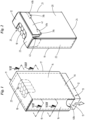
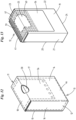
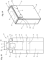
- a first, in the Fig. 1-11 The embodiment shown of a pack for elongated tobacco products, in the present case for a group of cigarettes 10, has an outer pack 11 and an inner pack 12 inserted or insertable therein.
- the outer packaging 11 is essentially cuboid-shaped with a bottom side 13 that is open at the bottom, via which the inner packaging 12 can be linearly moved or pulled out of the outer packaging 11 by a user.
- the outer pack 11, which serves to accommodate the inner pack 12 and is closed except for the open bottom side 13, has, in addition to the open bottom side 13, a first large-area side wall, namely a front wall 14, a second large-area side wall running in a plane parallel to this, namely a rear wall 15, two spaced-apart double-layered narrow side walls 16, 17 (double-layered from inner and outer side tabs 53, 55) which connect the front and rear walls 14, 15 and also run in planes parallel to one another, and an end wall 18 which is opposite the open bottom side 13 or is arranged at the end of the outer pack 11 opposite the bottom side 13.
- the inner pack 12 which is also essentially cuboid-shaped, is adapted to the outer pack 11 in terms of its shape and dimensions. It surrounds the pack contents, namely the group of cigarettes 10, on all sides. Accordingly, the inner pack 12 has a large-area inner side wall, namely an inner front wall 19, a second large-area inner side wall arranged in a parallel plane thereto, namely an inner rear wall 20, two inner narrow side walls 21, 22 (double-layered, made up of inner and outer inner side flaps 49, 52) which connect the inner front wall 19 and the inner rear wall 20 to one another and run in parallel planes at a distance from one another, as well as an inner front wall 23 and an inner bottom wall 24 at the upper and lower ends of the inner pack 12.
- a removal opening 25 is formed in the inner pack 12, which extends in the region of the inner front wall 19 and the inner end wall 23.
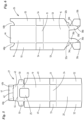
- Both the outer packaging 11 and the inner packaging 12 are each made from a one-piece blank 26 or 27, cf. Fig. 5, 6 , made from dimensionally stable material, such as (thin) cardboard.
- This cardboard can be coated on one or both sides, for example in such a way that the material as a whole becomes moisture- or aroma-tight.
- the inner packaging blank 27 could alternatively consist, at least for the most part, of non-dimensionally stable material, such as thin paper or the like (soft packaging).
- the inner packing 12 is mounted in the outer packing 11 so that it can move linearly.
- the outer packing 11 has on the inside in the region of its narrow side walls 16, 17 sliding guides 28a and 28b extending along the narrow side walls 16 and 17 from the open bottom side 13 in the direction of the end wall 18 and ending at a distance in front of the end wall 18.
- Each of these sliding guides 28a, 28b comprises a sliding slot 29a or 29b, which is assigned to one of the narrow side walls 16 or 17.
- the sliding slots 29a and 29b are each formed between the rear wall 15 of the outer packaging 11 and a cutting tab extending parallel and at a distance from the rear wall 15, namely a sliding leg 30a or 30b.
- the sliding legs 30a, 30b are arranged at a distance from one another in a common plane extending parallel to the rear wall 15, extend along the narrow side walls 16 or 17 from the open bottom side 14 to in front of the front wall 18 (ending at a distance from the latter in front of the latter) and protrude in their respective transverse extent starting from the respective narrow side wall 16 or 17 a little into the interior of the outer packaging 11.
- the sliding leg 30a is assigned to the narrow side wall 17 of the outer packaging 11, in this case fastened thereto, the sliding leg 30b is assigned to the narrow side wall 16 or fastened thereto.
- Sliding elements 31a and 31b of the inner packing 12 are mounted on the sliding guides 28a and 28b, respectively, as will be explained in more detail later.
- the sliding legs 30a, 30b are each folding tabs of the blank 26, which each adjoin the rear wall 15 of the outer packaging 11 and are connected to it via a folding line 32a or 32b.
- the sliding legs 30a, 30b are each folded around the folding line 32a or 32b to form the respective sliding slot 29a or 29b in the direction of the rear wall 15, so that they are then arranged in the common plane running parallel to the rear wall 15.
- each sliding leg 30a or 30b each connected to a side folding tab 33a or 33b of the blank 26 via a particularly perforated folding line 34a or 34b, wherein the respective side folding tabs 33a or 33b are folded over by 90° to the respective sliding leg 30a or 30b and in this position are connected to the associated narrow side wall 17 or 16, in the present case glued by means of adhesive portions 35.
- Each sliding leg 30a and 30b is assigned a spacer 36a or 36b, which rests on the rear wall 15 and ensures the distance between the sliding leg 30a or 30b and the rear wall 15.
- the respective spacer 36a, 36b is in this case a projection or folding tab arranged in the area of the fold line 34a or 34b and connected to the sliding leg 30a or 30b.
- Each sliding guide 28a, 28b also has a movement limiter that limits the linear movement of the inner packaging 12 out of the outer packaging 11 initiated by a user in such a way that the inner packaging 12 cannot be pulled out or moved out of the outer packaging with the inner packaging 12 completely separated or uncoupled from the outer packaging 11. Rather, the inner packaging 12 and the outer packaging 11 remain connected or coupled to one another even when the inner packaging 12 is completely pulled out of the outer packaging 11.
- each stop part comprises a folding edge 39, which is rounded in the present case and is arranged between the respective sliding leg 30a or 30b and the rear wall 15 and is formed by the folding of the respective sliding leg 30a, 30b along the associated folding line 32a or 32b, as described above.
- sliding elements 31a, 31b of the inner packaging 12 are formed by two spaced apart (free) sliding tab ends 40a and 40b of a sliding tab 41 designed as a folding tab of the blank 27 of the inner packaging 12.
- the sliding flap 41 is connected via a fold line 42 to a back flap 43 designed as a folding flap of the inner blank, which in turn is connected to the inner front wall 23 via a fold line 44.
- the back flap 43 lies on or against the inner rear wall 20 and is attached to it, preferably glued to it.
- the sliding flap 41 is folded around the fold line 42 in the direction of the back flap 43 to form a fold edge 45, so that the sliding flap 41 and the back flap 43 overlap each other, running essentially parallel to each other.
- one sliding tab end 40a of the sliding tab 41 engages in the sliding slot 29a associated with the narrow side wall 17, so that these overlap/cover in sections and the sliding tab end 40a is guided in it.
- the other sliding tab end 40b of the sliding tab 41 engages in the sliding slot 29b associated with the narrow side wall 16.
- the inner packaging 12 is connected to the outer packaging 11 in a captive manner via a particularly hinge-like pivot connection, wherein the pivot connection enables the inner packaging 12 to be pivoted relative to the outer packaging 11 in a plane perpendicular to the plane of the linear movement, so that a user can initiate the corresponding pivoting movement.
- the above-described folding edge 45 forms the pivot axis of the pivot connection between the outer packaging 11 and the inner packaging 12, around which the inner packaging 12 can be pivoted in the position of the inner packaging moved out of the outer packaging 11, cf. for example Fig. 9 , in which the sliding elements 31a, 31b of the inner packaging 12, namely in the present case the sliding tab ends 40a, 40b, each rest against the movement limiters 38a, 38b, can be pivoted relative to the outer packaging 11 by a user.
- FIG. 1 to 11 Another special feature of the packaging according to the Fig. 1 to 11 represent grip recesses 48a, 48b, which are located in the area of the Narrow side walls 16 and 17 of the outer packaging 11 are arranged.
- These grip recesses 48a, 48b are end recesses or cutouts in the narrow side walls 16 and 17, respectively, through which a user can touch the inner packaging 12 or grasp it with one finger each and can thus move it out of the outer packaging 11 via the open bottom side 13 by pulling or pushing.
- the front wall 14 of the outer package 11 has a resilient portion 46 which is formed by a (narrow) free end portion of the front wall 14.
- the free end section or the resilient section 46 has two free, spaced-apart longitudinal edges which are formed by end sections of the corresponding longitudinal edges of the outer pack 11 connecting the respective narrow side wall 16 or 17 to the front wall 14. Each of these two free longitudinal edges adjoins one of the grip recesses 48a or 48b in the narrow side walls 16 or 17 on one side.
- the resilient portion 46 further comprises a free transverse edge connecting the ends of the free longitudinal edges to one another, which at the same time delimits the open bottom side 13 on one side towards the outside.
- the inner pack 12 When the inner pack 12 is pivoted about the pivot axis of the pivot connection in the position moved out of the outer pack 11, in which the sliding members 31a, 31b of the inner pack 12 rest against the movement limiters 38a and 38b, the inner pack 12 is moved along the resilient section 46 of the front wall 14 of the outer pack 11 located in its path of movement, strikes against it, briefly pushes it out of its path of movement by pivoting the resilient section 46 (about a pivot axis running parallel to the transverse edge) and can then be moved further or past the resilient section 46, see in particular Fig. 9 .
- the dimensions of the inner packing 12 and the outer packing 11, the design of the linear guide of the inner packing 12 on the outer packing 11 and the pivoting connection between the inner packing 12 and the outer packing 11 are suitably coordinated with one another.
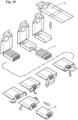
- the unfolded blanks 27 can, in a first step, be placed into the pocket 66 of a folding turret 67, cf. Fig. 23 , stamped and thereby brought into a first intermediate folding position, namely by erecting the inner front wall 19, the adjoining outer inner side flaps 49, the inner end wall 18, the adjoining back flap 43, the inner side corner flaps 50 and the sliding flap 41 adjoining the back caps 43. Furthermore, the inner bottom corner flaps 51 are folded and the inner inner side flaps 52.
- the cigarettes 10 are inserted into the inner pack 12 as a cigarette group in a next step.
- the inner front wall 19 is folded onto the cigarettes 10 of the cigarette group and the inner end wall 23 is folded together with the back flap 43, the sliding flap 41 and the inner side corner flaps 50 by 90° so that the inner end wall 23 comes to lie on the front side of the cigarette group.
- the back flap 43 is then folded onto the inner back wall 20 and the sliding flap 41 is folded around the fold line 42 onto the back flap 43 or in the direction of the same. Finally, the inner side corner flaps 50 are folded into the plane of the inner narrow side walls 21 or 22 and the outer inner side flaps 49 are folded onto the inner inner side flaps 52.
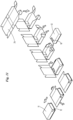
- the unfolded blanks 26 are again placed in the pocket of a Fig. 11 not shown folding turret and thereby brought into a first intermediate folding position, namely by erecting the front wall 14 with the adjoining end wall 18 and the adjoining outer side tabs 55. Furthermore, the inner side tabs 53 are folded as well as the side corner tabs 54.
- the front wall 14 of the outer package 11 is folded onto the associated inner front wall 19 of the inner package 12 and the outer side tabs 55 are folded over.
- the closure tab 56 is glued to the inner pack 12 by means of a non-releasable adhesive, in particular in the region of the inner rear wall 20 and in an adjacent region 59 of the inner front wall 23, and in the region 60 of the inner front wall 14 and in an adjacent region 61 of the inner front wall 18, in particular on both sides of the removal opening 25, with a releasable adhesive.
- the closure tab 56 also has a connecting section 57 which is attached to the outer pack 11 in such a way, in this case by means of a permanent adhesive connection, that the closure tab 56 is automatically at least partially pulled off the inner pack 12 when the inner pack 12 is moved relative to the outer pack 11, namely in this case when the inner pack 12 is pivoted relative to the outer pack 11, in order to remove at least one cigarette 10 while exposing the removal opening 25.
- the closure tab 56 is therefore automatically pulled off when a user initiates the above-mentioned relative movement.
- the connecting section 57 is attached or fastened for this purpose to an inner side of the outer packaging 11, namely in the present case to the inner side of the front wall 14 of the outer packaging 11.
- the closure tab 56 is preferably attached to the inside of the front wall 14 of the outer pack 11 in such a way that the removal opening 25 is already released by at least partially pulling off the closure tab 56 for removing at least one cigarette 10 when the inner pack 12 is only has been pivoted by an angle which has a value between 60° and 80°, preferably between 65° and 75°.
- the length of the closure tab 56 and its fastening to the inside of the front wall 14 is preferably selected such that the inner packaging 12 can be pivoted around the outer packaging 11 up to an angle of 180°. In particular, this can be done without destroying or overloading the permanent adhesive connection with which the aforementioned area(s) of the closure tab 56 is/are fastened to the inner packaging 12 and/or without destroying or overloading the permanent adhesive connection between the closure label 56 and the outer packaging 11.
- the packaging of the Fig. 12-17 is further distinguished by the fact that the sliding legs 30a and 30b and thus the sliding slots 29a, 29b of the outer packaging 11 and the sliding members 31a, 31b or the sliding tab ends 40a, 40b of the inner packaging 12 are coordinated with one another in such a way that the sliding tab ends 40a, 40b, when the inner packaging is fully inserted, are only a very small distance between 1 mm and 5 mm, preferably between 2 mm and 3 mm, from the sliding slots 29a, 29b, so that they engage in the sliding slots 29a, 29b immediately after the start of the linear movement moving the inner packaging 12 out of the outer packaging 11.
- the free, resilient (end) section 46 namely its two longitudinal edges, are in this case limited by two spaced apart, parallel, in the present case equally long incisions 47a, 47b in the area or along the respective edge of the pack between the front wall 14 and the respectively adjacent narrow side walls 16 and 17, in particular along the respective fold lines between the two outer side flaps 55 and the adjacent Front wall, the distance between which corresponds approximately to the transverse dimension of the inner front wall 19 of the inner package 12, which faces the front wall 14 of the outer package 11 when the inner package 12 is pushed into the outer package 11.
- the incisions 47a, 47b could also be made in the front wall 14 (at a distance from these package edges) if the front wall 14 is of a corresponding width.
- the outer packaging 11 of the pack extends Fig. 12-17 in the area of the end wall 18 and the front wall 14, a handle opening 58 through which a user can reach with a finger and push the inner package 12 out of the outer package 11.
- a (further) alternative embodiment of an inner package 12 is shown and in the Fig. 18 the matching blank 27 is shown.
- the inner packaging 12 can naturally be combined with any outer packaging variant shown in this application.
- the (comparatively shorter) closure tab 56 does not extend partially to the inner rear wall 20 and does not partially cover it or is not attached to it, but is glued exclusively to the inner front wall 19 and the inner end wall 23. This facilitates the manufacture of the inner packaging.
- the dorsal flap 43 tapers in the direction of the sliding flap 41, or the lateral (free) edges of the dorsal flap 43 run towards each other while reducing their distance from each other in the direction of the dorsal flap 43 (they are bevelled), so that the width of the dorsal flap 43 is reduced.
- the fold line 44 of the blank 27 is in this case designed as a weakening line, in particular as a perforation line, so that in comparison to the blank 27 of the inner pack 12 of the Fig. 14 Restoring forces are reduced which can occur during production when the back flap 43 is folded over onto the inner rear wall 20 and, in particular, when gluing the back flap 43, which could otherwise lead to a still fresh or not yet cured adhesive bond between the back flap 43 and the inner rear wall 20 coming loose again during production.
- Fig. 20 are the basic folding steps for producing the inner pack 12 of the Fig. 19 from cut 27 of the Fig. 18 These largely correspond to those of the Fig. 10 , but differ as follows: Unlike the folding sequence of the Fig. 10 Here, the inner front wall 19, the inner end wall 18, the rear flap 43 and the sliding flap 41, which are at this time in a common plane, are first folded together onto the cigarette group after the cigarette group has been inserted into the partially folded inner pack 12.
- the back flap 43, the inner end wall 23 and the sliding flap 41 are transferred together into an L-shape in which the inner end wall 23 is already largely arranged in its packaging-appropriate final position and the back flap 43 continues to be flush with it or is in a common plane with it, and in which the sliding flap 41 is folded into a position perpendicular to the back flap 43 and the inner end wall 23 (parallel to the inner front wall 19).
- the back flap 43 and the sliding flap 41 are then folded in a Z-shaped fold into the final position appropriate for the packaging, in which the back flap 43 rests against the inner rear wall 20 and the sliding flap 41 runs parallel to the back flap 43.
- the further folding steps (folding the inner side corner flaps 50 into the plane of the inner narrow side walls 21 and 22 and folding the outer inner side flaps 49 onto the inner inner side flaps 52) then correspond to those of the Fig. 10 .
- Fig. 21 are to the folding steps according to Fig. 11 alternative folding steps for producing the outer packaging 11 from Fig. 1 which are by far the same as those of the Fig. 11 but differ as follows: Unlike the folding process according to Fig. 11 the sliding legs 30a, 30b are transferred together with the front wall 14, the end wall 18 and the outer side flaps 55 of the blanks 26 into a or the first intermediate folding position, in which the sliding legs 30a, 30b (like the outer side flaps 55) then run perpendicular to the rear wall 15. The sliding legs 30a, 30b are then folded from this first intermediate folding position or into their (in connection with the Fig. 11 described in more detail) final position.
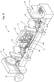
- FIG. 22-28 An embodiment of a packaging machine 62 for producing packages with such an outer package 11 and such an inner package 12 is shown in the Fig. 22-28 With the packaging machine 62, any package described in the present application (with outer package 11 and inner package 12) can be produced - if necessary with modifications that can be carried out by the person skilled in the art.
- the packaging machine 62 can, for example, have production units 63a-e arranged next to one another in a production line, in particular (but not necessarily) separable.
- the separable production unit 63a - forming unit - individual cigarettes 10 originating from a cigarette magazine 64 are formed into cigarette groups and then transferred to the production unit 63b, namely to a first folding unit, by means of a platform 65 that can be moved back and forth (in this case in a horizontal plane).
- the cigarette groups are each transferred into a pocket of a folding turret 67 (in this case rotating in a horizontal plane), in which a Fig. 20 partially pre-folded inner cut 27.
- the inner pack 12 is largely folded to the end in a manner described in more detail below, except for the outer inner side flaps 49, and then conveyed to a production unit 63c, in which the inner packs 12 are each provided with the closure flap 56 or the Closure label and rotated by 90° in two successive turning stations 68a and 68b so that they are transferred to the next production unit 63d in a position rotated by 180° relative to a straight conveyor path 94 of the production unit 63c, along which the inner packages 12 are each conveyed.
- the outer inner side tabs 49 are folded onto the inner inner side tabs 52 and glued to them.
- the inner packages 12 are each fed to a pocket 70 of a second folding turret 69 (which in this case also rotates in a horizontal plane) at an insertion station 93, in which an outer package 11 partially prefabricated or prefolded from the outer blank 26 is already located at the time of transfer.
- the outer blanks 26 were each previously fed to the folding turret 69 in a manner known per se and brought to the first intermediate folding position described in more detail above at a stamping station with the assistance of a folding shaft (not shown) with a movable stamping member 91, with partial folding, namely stamped into a pocket 70 of the folding turret 69.
- a movable folding member 92 arranged upstream of the insertion station 93 then ensures, after a partial rotation of the folding turret 69, the folding of the sliding legs 30a, 30b into their final position as described above.
- the outer packages 11 with the inner package 12 located therein are largely folded, except for the outer side flaps 55, and the closure flap 56 of the inner package 12 is attached (glued) to the outer blank 26 or the partially finished outer package 11.
- the packs are then conveyed to the production unit 63e, namely a curing unit.
- the production unit 63e namely a curing unit.
- One of the essential functions of the production unit 63e is to enable the curing of adhesive between the folded flaps of the inner pack 12 and/or outer pack 11 that are glued together.
- the production unit 63e can have, for example, two rotatable drying wheels or turrets 71a, b.
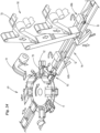
- the production of the inner packaging 12 in the production unit 63b is also carried out in a special way, see among other things the Fig. 23 , 25-28 : First, individual inner blanks 27 originating from a blank magazine 72 are fed to the folding turret 67 and are each stamped into a pocket 66 of the folding turret 67 provided by means of a movable stamping member 73 (stamping device), whereby they are transferred into the first intermediate folding position described above.
- a group of cigarettes is inserted at an insertion station 74 by means of a slider 75 from the platform 65 into the partially folded inner pack 12 held ready in the pocket 66.
- the inner front wall 19, the inner end wall 18, the rear flap 43 and the sliding flap 41 are first folded together onto the cigarette group by means of a (in this case vertically) movable folding member 76 - as already described above - and then folded in a preliminary L-position, cf. Fig. 25 in which the inner front wall 18 and the back flap 43 are folded against a first fixed guide 77, wherein in this position they are arranged in a plane which extends at an angle to the inner front wall 19 which deviates slightly from 90° with respect to the inner front wall 19.
- the effective guide surface 79 of the first stationary guide 77 runs accordingly at the same angle to the inner front wall 19.
- the sliding flap 41 is folded into a position parallel to the inner front wall 19, with the assistance of a second stationary guide 78 (sliding strip) with a horizontal, effective guide surface 80 against which the sliding flap 41 is pressed.
- Adjoining the first stationary guide 77 in the direction of rotation of the folding turret 67 at a short distance is a third stationary guide 81, which also runs in the circumferential direction of the turret and has an exactly vertically effective guide surface 82, which transfers the inner end wall 18 and the back flap 43 into a 90° position to the inner front wall 19 during a further partial rotation of the folding turret 67.
- one or more (hot melt) adhesive portions 84 are then applied to the back flap 43 by means of an adhesive application valve 85.
- the adhesive application valve 85 is arranged below the folding turret 67 or in the area of the underside thereof.
- the inner blank 27 in the pocket 66 is conveyed to a further, movable folding member 86, which then ensures the Z-shaped folding of the back flap 43 and the sliding flap 41 as already described above, with the back flap 43 resting against the inner rear wall 20.
Landscapes
- Engineering & Computer Science (AREA)
- Mechanical Engineering (AREA)
- Packaging Of Annular Or Rod-Shaped Articles, Wearing Apparel, Cassettes, Or The Like (AREA)
- Cartons (AREA)
Claims (19)
- Emballage pour un groupe de produits du tabac allongés (10), avec un emballage intérieur (12) pour un contenu d'emballage, de préférence pour un groupe de cigarettes, fabriqué à partir d'une découpe en formant au moins une paroi de fond, une paroi frontale, des parois latérales étroites et des parois latérales de grande surface, ainsi qu'avec un emballage extérieur (11) en un matériau indéformable, fabriqué à partir d'une découpe en formant au moins une paroi frontale, des parois latérales étroites et des parois latérales de grande surface, notamment en carton revêtu ou non revêtu, dans lequel l'emballage intérieur (12) est logé de manière déplaçable linéairement par rapport à l'emballage extérieur (11), de telle sorte que l'emballage intérieur (12) peut être sorti de l'emballage extérieur (11) par l'intermédiaire d'un côté de fond ouvert (13) de l'emballage extérieur (11), l'emballage extérieur (11) présentant un ou plusieurs limiteurs de déplacement (38a, 38b) coopérant avec l'emballage intérieur (12), qui limite/limitent ce déplacement linéaire de l'emballage intérieur (12) hors de l'emballage extérieur (11), et l'emballage extérieur (11) et l'emballage intérieur (12) étant reliés entre eux dans une position de l'emballage intérieur (12) sorti de l'emballage extérieur (11) par l'intermédiaire d'une liaison pivotante qui permet une capacité de pivotement de l'emballage intérieur (12) par rapport à l'emballage extérieur (11) dans un plan perpendiculaire au plan du déplacement linéaire, caractérisé en ce que l'emballage intérieur (12) est logé dans l'emballage extérieur (11) de manière déplaçable linéairement par rapport à l'emballage extérieur (11), par le fait que des organes de glissement (31a, 31b) de l'emballage intérieur (12) sont guidés le long de guides de glissement agencés dans l'emballage extérieur (11), les guides de glissement comprenant des fentes de glissement (29a, 29b) dans lesquelles s'engagent les organes de glissement (31a, 31b) de l'emballage intérieur (12) .
- Emballage selon la revendication 1, caractérisé en ce que l'emballage extérieur (11) présente deux fentes de glissement (29a, 29b) agencées à distance l'une de l'autre, qui sont formées respectivement entre l'une des parois latérales de grande surface de l'emballage extérieur (11) et respectivement une branche de glissement (30a, 30b) s'étendant parallèlement à distance de la paroi latérale de grande surface, notamment respectivement une branche de glissement (30a, 30b), qui est associée à une paroi latérale étroite de l'emballage extérieur (11), de préférence agencée sur celle-ci.
- Emballage selon la revendication 2, caractérisé en ce qu'à chaque branche de glissement (30a, 30b) est associée une entretoise, notamment une entretoise agencée sur celle-ci, qui s'appuie sur la paroi latérale de grande surface et assure la distance entre la branche de glissement respective (39a, 30b) et la paroi latérale de grande surface et/ou en ce que chaque branche de glissement (30a, 30b) est une patte de pliage de la découpe de l'emballage extérieur (11), adjacente à la paroi latérale de grande surface, reliée à celle-ci par l'intermédiaire d'une ligne de pliage, qui est repliée le long de la ligne de pliage en direction de la paroi latérale de grande surface, notamment dans un plan parallèle à celle-ci, en formant la fente de glissement (29a, 29b) .
- Emballage selon une ou plusieurs des revendications précédentes, caractérisé en ce qu'à chaque guide de glissement de l'emballage extérieur (11), notamment à chaque fente de glissement (29a, 29b), est associé un limiteur de déplacement (38a, 38b) qui est réalisé sous forme de pièce de butée, notamment un limiteur de déplacement (38a, 38b) contre lequel l'organe de glissement respectif (31a, 31b) de l'emballage intérieur (12) vient buter à la fin du déplacement linéaire.
- Emballage selon une ou plusieurs des revendications précédentes, caractérisé en ce que l'emballage intérieur (12) présente une ouverture de prélèvement (25) pour le prélèvement du contenu de l'emballage, notamment une ouverture de prélèvement (25) qui est recouverte par une languette de fermeture (56) agencée, notamment fixée, sur l'emballage intérieur (12), notamment au moyen d'une adhésion amovible, qui présente une section de liaison qui est fixée à l'emballage extérieur (11), notamment au moyen d'une liaison par adhésion inamovible, notamment sur un côté intérieur d'une paroi latérale de grande surface de l'emballage extérieur (11), de préférence le côté intérieur de la paroi avant de l'emballage extérieur (11), de telle sorte que la languette de fermeture (56), lors du déplacement de l'emballage intérieur (12) par rapport à l'emballage extérieur (11), notamment lors du pivotement de l'emballage intérieur (12) par rapport à l'emballage extérieur (11), est retirée (au moins partiellement) de l'emballage intérieur (12) en libérant l'ouverture de prélèvement (25) pour le prélèvement d'au moins un produit du tabac (10).
- Emballage selon la revendication 5, caractérisé en ce que l'ouverture de prélèvement (25) de l'emballage intérieur (12) s'étend dans la zone de la paroi frontale et de la paroi avant de l'emballage intérieur (12), et en ce que l'emballage intérieur (12) est agencé dans l'emballage extérieur (11) de telle sorte que la paroi frontale de l'emballage intérieur (12) est tournée vers la paroi frontale de l'emballage extérieur (11) et la paroi de fond de l'emballage intérieur (12) vers le côté de fond ouvert (13) de l'emballage extérieur (11).
- Emballage selon une ou plusieurs des revendications précédentes, caractérisé en ce que les organes de glissement (31a, 31b) de l'emballage intérieur (12) sont formés par deux extrémités de patte de glissement libres (40a, 40b), espacées l'une de l'autre, d'une patte de glissement reliée à l'emballage intérieur (12), qui pénètrent chacune dans l'une des fentes de glissement (29a, 29b) de l'emballage extérieur (11), en ce que la patte de glissement présentant les extrémités de patte de glissement (40a, 40b) est une patte de pliage de la découpe de l'emballage intérieur (12), qui est reliée par l'intermédiaire d'une ligne de pliage à une patte dorsale reliée à la paroi frontale de l'emballage intérieur (12), fixée à l'une des parois latérales de grande surface, notamment mise en adhésion avec celle-ci, la patte de glissement étant repliée autour de la ligne de pliage en direction de la patte dorsale en formant une arête de pliage, de telle sorte que la patte de glissement et la patte dorsale se recouvrent en s'étendant essentiellement parallèlement l'une à l'autre, et en ce que la patte dorsale est une patte de pliage de la découpe de l'emballage intérieur (12), qui est reliée à la paroi latérale de grande surface par l'intermédiaire d'une ligne de pliage réalisée de préférence sous forme de ligne d'affaiblissement, est repliée autour de cette ligne de pliage sur la paroi latérale de grande surface et est mise en adhésion avec celle-ci dans l'état replié.
- Emballage selon la revendication 7, caractérisé en ce que la patte dorsale est réalisée plus étroite que la patte de glissement dans la zone où elle est reliée à la patte de glissement par l'intermédiaire de la ligne de pliage, notamment de telle sorte que sa largeur se rétrécit en partant de la paroi latérale de grande surface en direction de la patte de glissement.
- Procédé de fabrication d'un emballage, de préférence d'un emballage selon une ou plusieurs des revendications précédentes, avec un emballage extérieur et un emballage intérieur pour un contenu d'emballage, notamment pour un groupe de produits du tabac allongés (10), logé à l'intérieur de manière déplaçable linéairement par rapport à l'emballage extérieur en guidant une patte de glissement de l'emballage intérieur sur des guides de glissement de l'emballage extérieur, de telle sorte que l'emballage intérieur (12) peut être sorti de l'emballage extérieur (11) par l'intermédiaire d'un côté de fond ouvert (13) de l'emballage extérieur (11), l'emballage extérieur présentant un limiteur de déplacement qui limite ce déplacement de l'emballage intérieur hors de l'emballage extérieur, l'emballage intérieur ainsi qu'un emballage extérieur contenant l'emballage intérieur étant fabriqués respectivement à partir d'une découpe d'emballage intérieur ou d'une découpe d'emballage extérieur en formant au moins une paroi de fond, une paroi frontale, des parois latérales étroites et des parois latérales de grande surface, les guides de glissement comprenant des fentes de glissement, la patte de glissement faisant partie de la découpe d'emballage intérieur, et dans le cadre de la fabrication de l'emballage, notamment pendant que la découpe d'emballage intérieur se trouve, de préférence conjointement avec le contenu de l'emballage, dans une poche d'un transporteur, notamment d'un revolver de pliage tournant de préférence dans un plan horizontal,a) une patte dorsale de la découpe d'emballage intérieur reliée à la patte de glissement étant repliée en s'appuyant sur celle-ci sur une première des parois latérales de grande surface et étant mise en adhésion avec celle-ci, etb) la patte de glissement étant pliée de telle sorte qu'elle s'étend parallèlement à la patte dorsale.
- Procédé selon la revendication 9, caractérisé en ce que la patte dorsale est reliée à la paroi frontale, et en ce qu'avant le repliage de la patte dorsale sur la première paroi latérale de grande surface, la patte dorsale, la paroi frontale et la patte de glissement sont transférées ensemble en une forme en L, de préférence à partir d'un état dans lequel une deuxième paroi latérale de grande surface parallèle à la première paroi frontale de grande surface, la patte dorsale, la paroi frontale et la patte de glissement sont alignées ou sont agencées dans le même plan, notamment par un déplacement cohérent d'un organe de pliage associé au transporteur.
- Procédé selon la revendication 10, caractérisé en ce que la patte dorsale, la paroi frontale et la patte de glissement sont transférés ensemble en une forme en L, notamment une forme en L dans laquelle la paroi frontale se trouve déjà dans sa position finale adaptée à l'emballage, par le fait quea) la patte dorsale est pliée conjointement avec la paroi frontale dans une position perpendiculaire à la première paroi latérale de grande surface, etb) la patte de glissement est pliée dans une position perpendiculaire à la patte dorsale et à la paroi frontale, dans laquelle la patte de glissement est parallèle à la première paroi latérale de grande surface.
- Procédé selon la revendication 10 ou 11, caractérisé en ce qu'après que la patte dorsale, la paroi frontale et la patte de glissement ont été transférées en forme en L, au moins une portion d'adhésif est appliquée sur la patte dorsale pour l'adhésion de la patte dorsale et de la première paroi latérale de grande surface.
- Procédé selon la revendication 12, caractérisé en ce que la poche dans laquelle se trouve la découpe d'emballage intérieur est agencée sur un premier côté, agencé parallèlement au plan de rotation, du transporteur réalisé sous forme de revolver de pliage, notamment sur le côté supérieur du revolver de pliage, et en ce que la portion d'adhésif est appliquée par une soupape d'application d'adhésif qui est positionnée dans la zone du deuxième côté opposé, agencé parallèlement au plan de rotation, du revolver de pliage, notamment dans la zone du côté inférieur du revolver de pliage.
- Procédé selon la revendication 10, 11, 12 ou 13, caractérisé en ce que la patte dorsale, la paroi frontale et la patte de glissement, notamment après l'application de la ou des portions d'adhésif, sont transférées de la forme en L à la position, notamment dans le cadre d'un pliage en Z, dans laquelle la patte dorsale est en appui contre la première paroi latérale de grande surface et la patte de glissement est parallèle à la patte dorsale.
- Procédé selon la revendication 14, caractérisé en ce que le transfert est effectué au moyen d'un seul organe de pliage associé au transporteur, dont le déplacement de transfert est un déplacement superposé d'un déplacement parallèle au premier côté de grande surface et d'un déplacement perpendiculaire au premier côté de grande surface.
- Procédé selon une ou plusieurs des revendications 9 à 15 précédentes, caractérisé en ce qu'une languette de fermeture utilisable plusieurs fois, recouvrant une ouverture de prélèvement (25) de l'emballage intérieur, est appliquée sur l'emballage intérieur partiellement ou définitivement plié en utilisant un adhésif amovible, de telle sorte que la languette de fermeture s'étend dans la zone de la paroi frontale de l'emballage intérieur et notamment de la deuxième paroi latérale de grande surface de l'emballage intérieur, mais pas dans la zone de la paroi latérale opposée, notamment la première paroi latérale de grande surface de l'emballage intérieur, et/ou en ce qu'une découpe d'emballage extérieur est tenue à disposition dans la poche d'un autre transporteur, notamment un deuxième revolver de pliage, et en ce que l'emballage intérieur partiellement ou finalement plié est transporté dans la poche avec la découpe d'emballage extérieur tenue à disposition.
- Procédé selon la revendication 16, caractérisé en ce que la découpe d'emballage extérieur est préalablement introduite dans la poche, notamment par estampage, et en ce que des branches de glissement de la découpe d'emballage extérieur, qui forment respectivement conjointement avec une paroi latérale de grande surface de l'emballage extérieur, notamment la paroi arrière, deux guides de glissement agencés à distance l'un de l'autre, notamment respectivement associés à une paroi latérale étroite de l'emballage extérieur, s'étendant parallèlement à la paroi latérale de grande surface, réalisés sous forme de fentes de glissement pour la patte de glissement de l'emballage intérieur, sont pliées dans une position perpendiculaire par rapport à la paroi latérale de grande surface, notamment au moyen d'au moins une paroi de pliage d'un puits de pliage.
- Procédé selon la revendication 17, caractérisé en ce que les branches de glissement sont ensuite pliées, notamment après un déplacement de transport du transporteur, de la position perpendiculaire à une position orientée parallèlement à la paroi latérale de grande surface de l'emballage extérieur.
- Procédé selon la revendication 18, caractérisé en ce que l'emballage intérieur est transporté, notamment inséré, dans la poche contenant la découpe d'emballage extérieur tenue à disposition, après que les branches de glissement ont été pliées dans la position parallèle, de préférence après un autre déplacement de transport du transporteur.
Applications Claiming Priority (2)
| Application Number | Priority Date | Filing Date | Title |
|---|---|---|---|
| DE102019004330.8A DE102019004330A1 (de) | 2019-06-20 | 2019-06-20 | Packung für Tabakerzeugnisse |
| PCT/EP2020/066718 WO2020254377A1 (fr) | 2019-06-20 | 2020-06-17 | Emballage destiné à des produits du tabac |
Publications (2)
| Publication Number | Publication Date |
|---|---|
| EP3986797A1 EP3986797A1 (fr) | 2022-04-27 |
| EP3986797B1 true EP3986797B1 (fr) | 2025-01-29 |
Family
ID=71465286
Family Applications (1)
| Application Number | Title | Priority Date | Filing Date |
|---|---|---|---|
| EP20736581.8A Active EP3986797B1 (fr) | 2019-06-20 | 2020-06-17 | Emballage destiné à des produits du tabac |
Country Status (3)
| Country | Link |
|---|---|
| EP (1) | EP3986797B1 (fr) |
| DE (1) | DE102019004330A1 (fr) |
| WO (1) | WO2020254377A1 (fr) |
Citations (1)
| Publication number | Priority date | Publication date | Assignee | Title |
|---|---|---|---|---|
| WO2010129621A1 (fr) * | 2009-05-05 | 2010-11-11 | Meadwestvaco Corporation | Emballages refermables |
Family Cites Families (12)
| Publication number | Priority date | Publication date | Assignee | Title |
|---|---|---|---|---|
| US2358802A (en) * | 1941-10-02 | 1944-09-26 | Box Blank Corp | Carton or container |
| US4784315A (en) * | 1987-10-09 | 1988-11-15 | Waldolf Corporation | Two piece sliding carton |
| GB9725768D0 (en) * | 1997-12-04 | 1998-02-04 | Rothmans International Ltd | Packaging of smoking articles |
| CN202828524U (zh) * | 2012-08-17 | 2013-03-27 | 湖北中烟工业有限责任公司 | 可重复使用的滑动抽拉式烟盒 |
| CN202864074U (zh) * | 2012-09-28 | 2013-04-10 | 湖北中烟工业有限责任公司 | 一种错位对开式双盒烟盒 |
| FR2998887B1 (fr) * | 2012-12-05 | 2015-05-22 | Franck Bovino | Perfectionnements aux emballages de paquets de produits consommables a l'unite laissant chacun un dechet jetable apres consommation |
| EP2990354A1 (fr) * | 2014-08-26 | 2016-03-02 | Reemtsma Cigarettenfabriken GmbH | Emballage pour des articles de tabac et/ou à fumer, ébauche et procédé associé |
| GB2530090A (en) * | 2014-09-15 | 2016-03-16 | British American Tobacco Co | Pack For Tobacco Industry Products |
| PL3356142T3 (pl) * | 2015-09-29 | 2020-11-16 | Philip Morris Products S.A. | Materiały opakowaniowe kontrolujące wilgoć |
| MX2018006039A (es) * | 2015-11-26 | 2018-08-15 | Philip Morris Products Sa | Paquete para bienes de consumo. |
| DE102015016456A1 (de) * | 2015-12-21 | 2017-06-22 | Focke & Co. (Gmbh & Co. Kg) | Packung für Zigaretten |
| ITUA20163648A1 (it) * | 2016-05-20 | 2017-11-20 | Gd Spa | Pacchetto rigido di articoli da fumo con coperchio e provvisto inferiormente di un contenitore estraibile. |
-
2019
- 2019-06-20 DE DE102019004330.8A patent/DE102019004330A1/de active Pending
-
2020
- 2020-06-17 EP EP20736581.8A patent/EP3986797B1/fr active Active
- 2020-06-17 WO PCT/EP2020/066718 patent/WO2020254377A1/fr not_active Ceased
Patent Citations (1)
| Publication number | Priority date | Publication date | Assignee | Title |
|---|---|---|---|---|
| WO2010129621A1 (fr) * | 2009-05-05 | 2010-11-11 | Meadwestvaco Corporation | Emballages refermables |
Also Published As
| Publication number | Publication date |
|---|---|
| EP3986797A1 (fr) | 2022-04-27 |
| DE102019004330A1 (de) | 2020-12-24 |
| WO2020254377A1 (fr) | 2020-12-24 |
Similar Documents
| Publication | Publication Date | Title |
|---|---|---|
| EP3194276B1 (fr) | Procédé et dispositif de fabrication de paquets de cigarettes | |
| EP2766282A1 (fr) | Paquet pour cigarettes et son procédé de fabrication | |
| EP0134550B1 (fr) | Emballage pour cigarettes muni d'un couvercle à charnière | |
| DE102008035467A1 (de) | (Zigaretten-)Packung sowie Zuschnitt, Verfahren und Vorrichtung zum Herstellen derselben | |
| EP2311632B1 (fr) | Emballage de cigarettes ainsi que procédé et dispositif de fabrication de celui-ci | |
| EP2977334B1 (fr) | Emballage de cigarettes et procédé et dispositif destinés à la fabrication de tels emballages | |
| DE102010027175A1 (de) | Weichpackung für Zigaretten | |
| WO1999002428A1 (fr) | Decoupe pour paquet de cigarettes | |
| EP2841358B1 (fr) | Étui à cigarettes et procédé pour le fabriquer | |
| DE3329455A1 (de) | Kappenschachtel fuer zigaretten oder dergleichen | |
| EP4069605B1 (fr) | Emballage pour produits de l'industrie du tabac | |
| WO1984004907A1 (fr) | Piece decoupee pour emballages parallelepipedes ou elements d'emballage | |
| DE10031319A1 (de) | Verfahren und Vorrichtung zum Herstellen von Klappschachteln mit Schließhilfe | |
| EP1023991B1 (fr) | Procédé et machine pour fabriquer des paquets de cigarettes | |
| EP3497038B1 (fr) | Paquet pour cigarettes et son procédé de fabrication | |
| EP3986797B1 (fr) | Emballage destiné à des produits du tabac | |
| EP2310280A1 (fr) | Emballage pour cigarettes ainsi que son procédé de fabrication | |
| DE3624345A1 (de) | Cigarettenschachtel | |
| WO2021116112A1 (fr) | Emballage pour produits de l'industrie du tabac, et procédé et appareil de production associés | |
| DE102019006687A1 (de) | Verfahren zum Einführen von Innenpackungen in eine Außenpackung | |
| EP3953273B1 (fr) | Emballage de type boîte à couvercle | |
| DE9010670U1 (de) | Weichpackung aus Kunststoffolie zur Aufnahme eines Stapels von gefalteten Erzeugnissen aus Papier, Tissue ect., insbesondere von Papiertaschentüchern und Servietten | |
| DE1934359A1 (de) | Zuschnitt fuer eine Schiebeschachtel und Verfahren zu deren Herstellung | |
| DE2513762A1 (de) | Einstueckiger karton und verfahren zum schliessen des kartons | |
| DE1015670B (de) | Vorrichtung zum Zusammenfuegen von Schachtelecken |
Legal Events
| Date | Code | Title | Description |
|---|---|---|---|
| STAA | Information on the status of an ep patent application or granted ep patent |
Free format text: STATUS: UNKNOWN |
|
| STAA | Information on the status of an ep patent application or granted ep patent |
Free format text: STATUS: THE INTERNATIONAL PUBLICATION HAS BEEN MADE |
|
| PUAI | Public reference made under article 153(3) epc to a published international application that has entered the european phase |
Free format text: ORIGINAL CODE: 0009012 |
|
| STAA | Information on the status of an ep patent application or granted ep patent |
Free format text: STATUS: REQUEST FOR EXAMINATION WAS MADE |
|
| 17P | Request for examination filed |
Effective date: 20211217 |
|
| AK | Designated contracting states |
Kind code of ref document: A1 Designated state(s): AL AT BE BG CH CY CZ DE DK EE ES FI FR GB GR HR HU IE IS IT LI LT LU LV MC MK MT NL NO PL PT RO RS SE SI SK SM TR |
|
| DAV | Request for validation of the european patent (deleted) | ||
| DAX | Request for extension of the european patent (deleted) | ||
| STAA | Information on the status of an ep patent application or granted ep patent |
Free format text: STATUS: EXAMINATION IS IN PROGRESS |
|
| 17Q | First examination report despatched |
Effective date: 20230816 |
|
| GRAP | Despatch of communication of intention to grant a patent |
Free format text: ORIGINAL CODE: EPIDOSNIGR1 |
|
| STAA | Information on the status of an ep patent application or granted ep patent |
Free format text: STATUS: GRANT OF PATENT IS INTENDED |
|
| INTG | Intention to grant announced |
Effective date: 20240911 |
|
| GRAS | Grant fee paid |
Free format text: ORIGINAL CODE: EPIDOSNIGR3 |
|
| GRAA | (expected) grant |
Free format text: ORIGINAL CODE: 0009210 |
|
| STAA | Information on the status of an ep patent application or granted ep patent |
Free format text: STATUS: THE PATENT HAS BEEN GRANTED |
|
| AK | Designated contracting states |
Kind code of ref document: B1 Designated state(s): AL AT BE BG CH CY CZ DE DK EE ES FI FR GB GR HR HU IE IS IT LI LT LU LV MC MK MT NL NO PL PT RO RS SE SI SK SM TR |
|
| REG | Reference to a national code |
Ref country code: GB Ref legal event code: FG4D Free format text: NOT ENGLISH |
|
| REG | Reference to a national code |
Ref country code: CH Ref legal event code: EP |
|
| P01 | Opt-out of the competence of the unified patent court (upc) registered |
Free format text: CASE NUMBER: APP_2464/2025 Effective date: 20250115 |
|
| REG | Reference to a national code |
Ref country code: DE Ref legal event code: R096 Ref document number: 502020010326 Country of ref document: DE |
|
| REG | Reference to a national code |
Ref country code: IE Ref legal event code: FG4D Free format text: LANGUAGE OF EP DOCUMENT: GERMAN |
|
| REG | Reference to a national code |
Ref country code: NL Ref legal event code: MP Effective date: 20250129 |
|
| PG25 | Lapsed in a contracting state [announced via postgrant information from national office to epo] |
Ref country code: NL Free format text: LAPSE BECAUSE OF FAILURE TO SUBMIT A TRANSLATION OF THE DESCRIPTION OR TO PAY THE FEE WITHIN THE PRESCRIBED TIME-LIMIT Effective date: 20250129 |
|
| PG25 | Lapsed in a contracting state [announced via postgrant information from national office to epo] |
Ref country code: RS Free format text: LAPSE BECAUSE OF FAILURE TO SUBMIT A TRANSLATION OF THE DESCRIPTION OR TO PAY THE FEE WITHIN THE PRESCRIBED TIME-LIMIT Effective date: 20250429 |
|
| PG25 | Lapsed in a contracting state [announced via postgrant information from national office to epo] |
Ref country code: FI Free format text: LAPSE BECAUSE OF FAILURE TO SUBMIT A TRANSLATION OF THE DESCRIPTION OR TO PAY THE FEE WITHIN THE PRESCRIBED TIME-LIMIT Effective date: 20250129 |
|
| PG25 | Lapsed in a contracting state [announced via postgrant information from national office to epo] |
Ref country code: PL Free format text: LAPSE BECAUSE OF FAILURE TO SUBMIT A TRANSLATION OF THE DESCRIPTION OR TO PAY THE FEE WITHIN THE PRESCRIBED TIME-LIMIT Effective date: 20250129 |
|
| PG25 | Lapsed in a contracting state [announced via postgrant information from national office to epo] |
Ref country code: ES Free format text: LAPSE BECAUSE OF FAILURE TO SUBMIT A TRANSLATION OF THE DESCRIPTION OR TO PAY THE FEE WITHIN THE PRESCRIBED TIME-LIMIT Effective date: 20250129 |
|
| REG | Reference to a national code |
Ref country code: LT Ref legal event code: MG9D |
|
| PG25 | Lapsed in a contracting state [announced via postgrant information from national office to epo] |
Ref country code: IS Free format text: LAPSE BECAUSE OF FAILURE TO SUBMIT A TRANSLATION OF THE DESCRIPTION OR TO PAY THE FEE WITHIN THE PRESCRIBED TIME-LIMIT Effective date: 20250529 Ref country code: NO Free format text: LAPSE BECAUSE OF FAILURE TO SUBMIT A TRANSLATION OF THE DESCRIPTION OR TO PAY THE FEE WITHIN THE PRESCRIBED TIME-LIMIT Effective date: 20250429 |
|
| PG25 | Lapsed in a contracting state [announced via postgrant information from national office to epo] |
Ref country code: HR Free format text: LAPSE BECAUSE OF FAILURE TO SUBMIT A TRANSLATION OF THE DESCRIPTION OR TO PAY THE FEE WITHIN THE PRESCRIBED TIME-LIMIT Effective date: 20250129 |
|
| PG25 | Lapsed in a contracting state [announced via postgrant information from national office to epo] |
Ref country code: LV Free format text: LAPSE BECAUSE OF FAILURE TO SUBMIT A TRANSLATION OF THE DESCRIPTION OR TO PAY THE FEE WITHIN THE PRESCRIBED TIME-LIMIT Effective date: 20250129 Ref country code: PT Free format text: LAPSE BECAUSE OF FAILURE TO SUBMIT A TRANSLATION OF THE DESCRIPTION OR TO PAY THE FEE WITHIN THE PRESCRIBED TIME-LIMIT Effective date: 20250529 |
|
| PG25 | Lapsed in a contracting state [announced via postgrant information from national office to epo] |
Ref country code: GR Free format text: LAPSE BECAUSE OF FAILURE TO SUBMIT A TRANSLATION OF THE DESCRIPTION OR TO PAY THE FEE WITHIN THE PRESCRIBED TIME-LIMIT Effective date: 20250430 Ref country code: BG Free format text: LAPSE BECAUSE OF FAILURE TO SUBMIT A TRANSLATION OF THE DESCRIPTION OR TO PAY THE FEE WITHIN THE PRESCRIBED TIME-LIMIT Effective date: 20250129 |
|
| PG25 | Lapsed in a contracting state [announced via postgrant information from national office to epo] |
Ref country code: SE Free format text: LAPSE BECAUSE OF FAILURE TO SUBMIT A TRANSLATION OF THE DESCRIPTION OR TO PAY THE FEE WITHIN THE PRESCRIBED TIME-LIMIT Effective date: 20250129 |
|
| PG25 | Lapsed in a contracting state [announced via postgrant information from national office to epo] |
Ref country code: SM Free format text: LAPSE BECAUSE OF FAILURE TO SUBMIT A TRANSLATION OF THE DESCRIPTION OR TO PAY THE FEE WITHIN THE PRESCRIBED TIME-LIMIT Effective date: 20250129 |
|
| PG25 | Lapsed in a contracting state [announced via postgrant information from national office to epo] |
Ref country code: DK Free format text: LAPSE BECAUSE OF FAILURE TO SUBMIT A TRANSLATION OF THE DESCRIPTION OR TO PAY THE FEE WITHIN THE PRESCRIBED TIME-LIMIT Effective date: 20250129 |
|
| PGFP | Annual fee paid to national office [announced via postgrant information from national office to epo] |
Ref country code: IT Payment date: 20250618 Year of fee payment: 6 |
|
| PG25 | Lapsed in a contracting state [announced via postgrant information from national office to epo] |
Ref country code: CZ Free format text: LAPSE BECAUSE OF FAILURE TO SUBMIT A TRANSLATION OF THE DESCRIPTION OR TO PAY THE FEE WITHIN THE PRESCRIBED TIME-LIMIT Effective date: 20250129 Ref country code: EE Free format text: LAPSE BECAUSE OF FAILURE TO SUBMIT A TRANSLATION OF THE DESCRIPTION OR TO PAY THE FEE WITHIN THE PRESCRIBED TIME-LIMIT Effective date: 20250129 |
|
| PG25 | Lapsed in a contracting state [announced via postgrant information from national office to epo] |
Ref country code: RO Free format text: LAPSE BECAUSE OF FAILURE TO SUBMIT A TRANSLATION OF THE DESCRIPTION OR TO PAY THE FEE WITHIN THE PRESCRIBED TIME-LIMIT Effective date: 20250129 |
|
| PG25 | Lapsed in a contracting state [announced via postgrant information from national office to epo] |
Ref country code: SK Free format text: LAPSE BECAUSE OF FAILURE TO SUBMIT A TRANSLATION OF THE DESCRIPTION OR TO PAY THE FEE WITHIN THE PRESCRIBED TIME-LIMIT Effective date: 20250129 |
|
| REG | Reference to a national code |
Ref country code: DE Ref legal event code: R097 Ref document number: 502020010326 Country of ref document: DE |
|
| PLBE | No opposition filed within time limit |
Free format text: ORIGINAL CODE: 0009261 |
|
| STAA | Information on the status of an ep patent application or granted ep patent |
Free format text: STATUS: NO OPPOSITION FILED WITHIN TIME LIMIT |
|
| REG | Reference to a national code |
Ref country code: CH Ref legal event code: L10 Free format text: ST27 STATUS EVENT CODE: U-0-0-L10-L00 (AS PROVIDED BY THE NATIONAL OFFICE) Effective date: 20251210 |
|
| REG | Reference to a national code |
Ref country code: DE Ref legal event code: R119 Ref document number: 502020010326 Country of ref document: DE |
|
| 26N | No opposition filed |
Effective date: 20251030 |
|
| REG | Reference to a national code |
Ref country code: CH Ref legal event code: H13 Free format text: ST27 STATUS EVENT CODE: U-0-0-H10-H13 (AS PROVIDED BY THE NATIONAL OFFICE) Effective date: 20260127 |
|
| PG25 | Lapsed in a contracting state [announced via postgrant information from national office to epo] |
Ref country code: MC Free format text: LAPSE BECAUSE OF FAILURE TO SUBMIT A TRANSLATION OF THE DESCRIPTION OR TO PAY THE FEE WITHIN THE PRESCRIBED TIME-LIMIT Effective date: 20250129 |
|
| PG25 | Lapsed in a contracting state [announced via postgrant information from national office to epo] |
Ref country code: LU Free format text: LAPSE BECAUSE OF NON-PAYMENT OF DUE FEES Effective date: 20250617 |
|
| GBPC | Gb: european patent ceased through non-payment of renewal fee |
Effective date: 20250617 |
|
| REG | Reference to a national code |
Ref country code: BE Ref legal event code: MM Effective date: 20250630 |
|
| PG25 | Lapsed in a contracting state [announced via postgrant information from national office to epo] |
Ref country code: GB Free format text: LAPSE BECAUSE OF NON-PAYMENT OF DUE FEES Effective date: 20250617 |
|
| PG25 | Lapsed in a contracting state [announced via postgrant information from national office to epo] |
Ref country code: IE Free format text: LAPSE BECAUSE OF NON-PAYMENT OF DUE FEES Effective date: 20250617 Ref country code: DE Free format text: LAPSE BECAUSE OF NON-PAYMENT OF DUE FEES Effective date: 20260101 |
|
| PG25 | Lapsed in a contracting state [announced via postgrant information from national office to epo] |
Ref country code: BE Free format text: LAPSE BECAUSE OF NON-PAYMENT OF DUE FEES Effective date: 20250630 |
|
| PG25 | Lapsed in a contracting state [announced via postgrant information from national office to epo] |
Ref country code: FR Free format text: LAPSE BECAUSE OF NON-PAYMENT OF DUE FEES Effective date: 20250630 |
|
| PG25 | Lapsed in a contracting state [announced via postgrant information from national office to epo] |
Ref country code: CH Free format text: LAPSE BECAUSE OF NON-PAYMENT OF DUE FEES Effective date: 20250630 |