EP3987760B1 - Dispositif électronique pour identifier un dispositif électronique externe, et procédé de commande associé - Google Patents
Dispositif électronique pour identifier un dispositif électronique externe, et procédé de commande associé Download PDFInfo
- Publication number
- EP3987760B1 EP3987760B1 EP20869119.6A EP20869119A EP3987760B1 EP 3987760 B1 EP3987760 B1 EP 3987760B1 EP 20869119 A EP20869119 A EP 20869119A EP 3987760 B1 EP3987760 B1 EP 3987760B1
- Authority
- EP
- European Patent Office
- Prior art keywords
- electronic device
- external electronic
- data rate
- time point
- changes
- Prior art date
- Legal status (The legal status is an assumption and is not a legal conclusion. Google has not performed a legal analysis and makes no representation as to the accuracy of the status listed.)
- Active
Links
Images




Classifications
-
- H—ELECTRICITY
- H04—ELECTRIC COMMUNICATION TECHNIQUE
- H04M—TELEPHONIC COMMUNICATION
- H04M1/00—Substation equipment, e.g. for use by subscribers
- H04M1/72—Mobile telephones; Cordless telephones, i.e. devices for establishing wireless links to base stations without route selection
- H04M1/724—User interfaces specially adapted for cordless or mobile telephones
- H04M1/72403—User interfaces specially adapted for cordless or mobile telephones with means for local support of applications that increase the functionality
- H04M1/72409—User interfaces specially adapted for cordless or mobile telephones with means for local support of applications that increase the functionality by interfacing with external accessories
- H04M1/72412—User interfaces specially adapted for cordless or mobile telephones with means for local support of applications that increase the functionality by interfacing with external accessories using two-way short-range wireless interfaces
-
- H—ELECTRICITY
- H04—ELECTRIC COMMUNICATION TECHNIQUE
- H04B—TRANSMISSION
- H04B17/00—Monitoring; Testing
- H04B17/30—Monitoring; Testing of propagation channels
- H04B17/309—Measuring or estimating channel quality parameters
-
- H—ELECTRICITY
- H04—ELECTRIC COMMUNICATION TECHNIQUE
- H04L—TRANSMISSION OF DIGITAL INFORMATION, e.g. TELEGRAPHIC COMMUNICATION
- H04L43/00—Arrangements for monitoring or testing data switching networks
- H04L43/08—Monitoring or testing based on specific metrics, e.g. QoS, energy consumption or environmental parameters
- H04L43/0876—Network utilisation, e.g. volume of load or congestion level
- H04L43/0894—Packet rate
-
- H—ELECTRICITY
- H04—ELECTRIC COMMUNICATION TECHNIQUE
- H04L—TRANSMISSION OF DIGITAL INFORMATION, e.g. TELEGRAPHIC COMMUNICATION
- H04L43/00—Arrangements for monitoring or testing data switching networks
- H04L43/16—Threshold monitoring
-
- H—ELECTRICITY
- H04—ELECTRIC COMMUNICATION TECHNIQUE
- H04W—WIRELESS COMMUNICATION NETWORKS
- H04W12/00—Security arrangements; Authentication; Protecting privacy or anonymity
- H04W12/12—Detection or prevention of fraud
- H04W12/121—Wireless intrusion detection systems [WIDS]; Wireless intrusion prevention systems [WIPS]
- H04W12/122—Counter-measures against attacks; Protection against rogue devices
-
- H—ELECTRICITY
- H04—ELECTRIC COMMUNICATION TECHNIQUE
- H04W—WIRELESS COMMUNICATION NETWORKS
- H04W24/00—Supervisory, monitoring or testing arrangements
- H04W24/08—Testing, supervising or monitoring using real traffic
-
- H—ELECTRICITY
- H04—ELECTRIC COMMUNICATION TECHNIQUE
- H04M—TELEPHONIC COMMUNICATION
- H04M2201/00—Electronic components, circuits, software, systems or apparatus used in telephone systems
- H04M2201/34—Microprocessors
-
- H—ELECTRICITY
- H04—ELECTRIC COMMUNICATION TECHNIQUE
- H04M—TELEPHONIC COMMUNICATION
- H04M2201/00—Electronic components, circuits, software, systems or apparatus used in telephone systems
- H04M2201/36—Memories
-
- H—ELECTRICITY
- H04—ELECTRIC COMMUNICATION TECHNIQUE
- H04M—TELEPHONIC COMMUNICATION
- H04M2201/00—Electronic components, circuits, software, systems or apparatus used in telephone systems
- H04M2201/38—Displays
-
- H—ELECTRICITY
- H04—ELECTRIC COMMUNICATION TECHNIQUE
- H04M—TELEPHONIC COMMUNICATION
- H04M2250/00—Details of telephonic subscriber devices
- H04M2250/06—Details of telephonic subscriber devices including a wireless LAN interface
-
- H—ELECTRICITY
- H04—ELECTRIC COMMUNICATION TECHNIQUE
- H04W—WIRELESS COMMUNICATION NETWORKS
- H04W8/00—Network data management
- H04W8/005—Discovery of network devices, e.g. terminals
Definitions
- Various embodiments can provide an electronic device and a method of operating the same, which can identify whether a camera is present, as well as whether a space captured by a camera is a space where a user is present.
- FIGS. 1 through 12 discussed below, and the various embodiments used to describe the principles of the present disclosure in this patent document are by way of illustration only and should not be construed in any way to limit the scope of the claims. Those skilled in the art will understand that the principles of the present disclosure may be implemented in any suitably arranged system or device.
- FIG. 1 is a block diagram illustrating an electronic device 101 in a network environment 100.
- the electronic device 101 in the network environment 100 may communicate with an electronic device 102 via a first network 198 (e.g., a short-range wireless communication network), or an electronic device 104 or a server 108 via a second network 199 (e.g., a long-range wireless communication network).
- the electronic device 101 may communicate with the electronic device 104 via the server 108.
- the electronic device 101 may include a processor 120, memory 130, an input device 150, a sound output device 155, a display device 160, an audio module 170, a sensor module 176, an interface 177, a haptic module 179, a camera module 180, a power management module 188, a battery 189, a communication module 190, a subscriber identification module (SIM) 196, or an antenna module 197.
- At least one (e.g., the display device 160 or the camera module 180) of the components may be omitted from the electronic device 101, or one or more other components may be added in the electronic device 101.
- the sensor module 176 e.g., a fingerprint sensor, an iris sensor, or an illuminance sensor
- the display device 160 e.g., a display
- the sensor module 176 e.g., a fingerprint sensor, an iris sensor, or an illuminance sensor
- the processor 120 may execute, for example, software (e.g., a program 140) to control at least one other component (e.g., a hardware or software component) of the electronic device 101 coupled with the processor 120, and may perform various data processing or computation. As at least part of the data processing or computation, the processor 120 may load a command or data received from another component (e.g., the sensor module 176 or the communication module 190) in volatile memory 132, process the command or the data stored in the volatile memory 132, and store resulting data in non-volatile memory 134.
- software e.g., a program 140
- the processor 120 may load a command or data received from another component (e.g., the sensor module 176 or the communication module 190) in volatile memory 132, process the command or the data stored in the volatile memory 132, and store resulting data in non-volatile memory 134.
- the auxiliary processor 123 may control, for example, at least some of functions or states related to at least one component (e.g., the display device 160, the sensor module 176, or the communication module 190) among the components of the electronic device 101, instead of the main processor 121 while the main processor 121 is in an inactive (e.g., sleep) state, or together with the main processor 121 while the main processor 121 is in an active (e.g., executing an application) state.
- the auxiliary processor 123 e.g., an image signal processor or a communication processor
- the memory 130 may store various data used by at least one component (e.g., the processor 120 or the sensor module 176) of the electronic device 101.
- the various data may include, for example, software (e.g., the program 140) and input data or output data for a command related thereto.
- the memory 130 may include the volatile memory 132 or the non-volatile memory 134.
- the input device 150 may receive a command or data to be used by a component (e.g., the processor 120) of the electronic device 101, from the outside (e.g., a user) of the electronic device 101.
- the input device 150 may include, for example, a microphone, a mouse, a keyboard, or a digital pen (e.g., a stylus pen).
- the sound output device 155 may output sound signals to the outside of the electronic device 101.
- the sound output device 155 may include, for example, a speaker or a receiver.
- the speaker may be used for general purposes, such as playing multimedia or playing record, and the receiver may be used for incoming calls.
- the receiver may be implemented as separate from, or as part of the speaker.
- the display device 160 may visually provide information to the outside (e.g., a user) of the electronic device 101.
- the display device 160 may include, for example, a display, a hologram device, or a projector and control circuitry to control a corresponding one of the display, hologram device, and projector.
- the display device 160 may include touch circuitry adapted to detect a touch, or sensor circuitry (e.g., a pressure sensor) adapted to measure the intensity of force incurred by the touch.
- the audio module 170 may convert a sound into an electrical signal and vice versa.
- the audio module 170 may obtain the sound via the input device 150, or output the sound via the sound output device 155 or an external electronic device (e.g., an electronic device 102 (e.g., a speaker or a headphone)) directly or wirelessly coupled with the electronic device 101.
- an electronic device 102 e.g., a speaker or a headphone
- the sensor module 176 may detect an operational state (e.g., power or temperature) of the electronic device 101 or an environmental state (e.g., a state of a user) external to the electronic device 101, and then generate an electrical signal or data value corresponding to the detected state.
- the sensor module 176 may include, for example, a gesture sensor, a gyro sensor, an atmospheric pressure sensor, a magnetic sensor, an acceleration sensor, a grip sensor, a proximity sensor, a color sensor, an infrared (IR) sensor, a biometric sensor, a temperature sensor, a humidity sensor, or an illuminance sensor.
- the interface 177 may support one or more specified protocols to be used for the electronic device 101 to be coupled with the external electronic device (e.g., the electronic device 102) directly or wirelessly.
- the interface 177 may include, for example, a high definition multimedia interface (HDMI), a universal serial bus (USB) interface, a secure digital (SD) card interface, or an audio interface.
- HDMI high definition multimedia interface
- USB universal serial bus
- SD secure digital
- a connecting terminal 178 may include a connector via which the electronic device 101 may be physically connected with the external electronic device (e.g., the electronic device 102).
- the connecting terminal 178 may include, for example, a HDMI connector, a USB connector, a SD card connector, or an audio connector (e.g., a headphone connector).
- the haptic module 179 may convert an electrical signal into a mechanical stimulus (e.g., a vibration or a movement) or electrical stimulus which may be recognized by a user via his tactile sensation or kinesthetic sensation.
- the haptic module 179 may include, for example, a motor, a piezoelectric element, or an electric stimulator.
- the camera module 180 may capture a still image or moving images.
- the camera module 180 may include one or more lenses, image sensors, image signal processors, or flashes.
- the power management module 188 may manage power supplied to the electronic device 101.
- the power management module 188 may be implemented as at least part of, for example, a power management integrated circuit (PMIC).
- PMIC power management integrated circuit
- the battery 189 may supply power to at least one component of the electronic device 101.
- the battery 189 may include, for example, a primary cell which is not rechargeable, a secondary cell which is rechargeable, or a fuel cell.
- the communication module 190 may support establishing a direct (e.g., wired) communication channel or a wireless communication channel between the electronic device 101 and the external electronic device (e.g., the electronic device 102, the electronic device 104, or the server 108) and performing communication via the established communication channel.
- the communication module 190 may include one or more communication processors that are operable independently from the processor 120 (e.g., the application processor (AP)) and supports a direct (e.g., wired) communication or a wireless communication.
- AP application processor
- the communication module 190 may include a wireless communication module 192 (e.g., a cellular communication module, a short-range wireless communication module, or a global navigation satellite system (GNSS) communication module) or a wired communication module 194 (e.g., a local area network (LAN) communication module or a power line communication (PLC) module).
- a wireless communication module 192 e.g., a cellular communication module, a short-range wireless communication module, or a global navigation satellite system (GNSS) communication module
- GNSS global navigation satellite system
- wired communication module 194 e.g., a local area network (LAN) communication module or a power line communication (PLC) module.
- a corresponding one of these communication modules may communicate with the external electronic device via the first network 198 (e.g., a short-range communication network, such as BluetoothTM, wireless-fidelity (Wi-Fi) direct, or infrared data association (IrDA)) or the second network 199 (e.g., a long-range communication network, such as a cellular network, the Internet, or a computer network (e.g., LAN or wide area network (WAN)).
- the first network 198 e.g., a short-range communication network, such as BluetoothTM, wireless-fidelity (Wi-Fi) direct, or infrared data association (IrDA)
- the second network 199 e.g., a long-range communication network, such as a cellular network, the Internet, or a computer network (e.g., LAN or wide area network (WAN)
- These various types of communication modules may be implemented as a single component (e.g., a single chip), or may be implemented as multi components (e.
- the wireless communication module 192 may identify and authenticate the electronic device 101 in a communication network, such as the first network 198 or the second network 199, using subscriber information (e.g., international mobile subscriber identity (IMSI)) stored in the subscriber identification module 196.
- subscriber information e.g., international mobile subscriber identity (IMSI)
- the antenna module 197 may transmit or receive a signal or power to or from the outside (e.g., the external electronic device) of the electronic device 101.
- the antenna module 197 may include an antenna including a radiating element composed of a conductive material or a conductive pattern formed in or on a substrate (e.g., PCB).
- the antenna module 197 may include a plurality of antennas. In such a case, at least one antenna appropriate for a communication scheme used in the communication network, such as the first network 198 or the second network 199, may be selected, for example, by the communication module 190 from the plurality of antennas. The signal or the power may then be transmitted or received between the communication module 190 and the external electronic device via the selected at least one antenna.
- Another component e.g., a radio frequency integrated circuit (RFIC)
- RFIC radio frequency integrated circuit
- Commands or data may be transmitted or received between the electronic device 101 and the external electronic device 104 via the server 108 coupled with the second network 199.
- Each of the electronic devices 102 and 104 may be a device of a same type as, or a different type, from the electronic device 101. All or some of operations to be executed at the electronic device 101 may be executed at one or more of the external electronic devices 102, 104, or 108. For example, if the electronic device 101 should perform a function or a service automatically, or in response to a request from a user or another device, the electronic device 101, instead of, or in addition to, executing the function or the service, may request the one or more external electronic devices to perform at least part of the function or the service.
- the processor 201 acquires data rate information on at least one external electronic device through the communication module 205.
- the data rate information may refer to time-series information of the data rate for each of at least one external electronic device connected to an access point.
- the data rate information indicates a data rate of at least one external electronic device during an arbitrary time period.
- the processor 201 may identify a header field of a communication signal transmitted from an external electronic device.
- the header field may include, for example, a source address and a destination address of a communication signal and a size of a packet to be transmitted.
- the processor 201 may identify the data rate based on the size of a packet corresponding to an arbitrary source address. Accordingly, the processor 201 may identify time-series information of the data rate by continuously identifying the header field of a plurality of communication signals transmitted by an arbitrary external electronic device.
- the processor 201 identifies a first external electronic device having a data rate pattern corresponding to a first condition based on the data rate information.
- the data rate pattern may be time-series information of a data rate for one external electronic device among at least one external electronic device.
- the processor 201 may identify whether there is a data rate pattern representing real-time streaming among data rate patterns of the at least one external electronic device.
- the processor 201 may identify, when the size of the data rate is constant, that this is a data rate pattern representing real-time streaming.
- the fact that the size of the data rate is constant may include a case where the amount of change in the data rate is less than or equal to a threshold value.
- the processor 201 identifies channel state information (CSI) of a channel through which the first external electronic device performs communication through the communication module 205.
- CSI channel state information
- the processor 201 identifies a CSI pattern of the channel through which the first external electronic device performs communication in an arbitrary time interval, based on CSI on the channel through which the first external electronic device performs communication.
- the CSI pattern may refer to time-series information of the CSI on the first external electronic device.
- the processor 201 identifies whether a data rate pattern of the first external electronic device matches the CSI pattern of the channel.
- a time point at which the data rate of the first external electronic device changes corresponds to a time point at which the CSI of the channel changes
- the processor 201 determines that the data rate pattern of the first external electronic device matches the CSI pattern of the channel.
- the fact that the time point at which the data rate of the first external electronic device changes corresponds to the time point at which the CSI of the channel changes may include a case in which the two time points coincide with each other or a case having an error corresponding to a processing time to transmit a video captured by the first external electronic device.
- CSI may change.
- the data size of a video capturing the movement of the object may also be changed by the movement of the object.
- the data size of the captured video may be the size of data obtained by encoding the captured video.
- the processor 201 may determine whether there is a camera capturing the space where the electronic device 200 is located, based on whether a time point of a change in various factors (e.g., received signal strength indicator (RSSI), reference signal received quality (RSSQ), etc.) capable of indicating a channel matches a time point of a change in the data rate, as well as whether the CSI matches the data rate.
- RSSI received signal strength indicator
- RSSQ reference signal received quality
- the processor 201 identifies whether the space where the electronic device 200 is located is captured by the first external electronic device, based on whether the matching is performed. For example, the processor 201 may notify that the first external electronic device is present using the display 207.
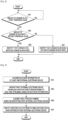
- FIG. 3 illustrates a flowchart of a method for operating an electronic device. The embodiment of FIG. 3 will be described in more detail with reference to FIGS. 4A, 4B, 5A , and 5B .
- FIG. 4A illustrates a data rate pattern.
- FIG. 4B illustrates a data rate pattern.
- FIG. 5A illustrates a data rate pattern.
- FIG. 5B illustrates a data rate pattern.
- the electronic device 101 identifies a first external electronic device having a data rate pattern corresponding to a first condition among the at least one external electronic device, based on data rate information.
- FIG. 4A illustrates a data rate pattern for streaming a video obtained by capturing a static space in real time.
- the size of the transmitted data may be constant.
- FIG. 4B when a video (e.g., a movie) is played, the size of data to be transmitted may be different for each frame, so that the data rate may not be constant.
- the electronic device 101 may identify that the constant data rate corresponds to the first condition. Meanwhile, the fact that the data rate is constant may include a case in which the change in the data rate is less than or equal to a threshold value.
- an access point (AP) 501 may be connected to the electronic device 101, a first external electronic device 511, a second external electronic device 513, a third external electronic device 515, and a fourth external electronic device 517.
- the number of external electronic devices connected to the AP 501 is irrelevant.
- the first external electronic device 511 may be a camera capturing a video.
- the second external electronic device 513 may be executing a social network service (SNS) application.
- the third external electronic device 515 may be executing a game application.
- the fourth external electronic device 517 may be executing a video reproduction application.
- the electronic device 101 acquires data rate information on a plurality of external electronic devices 511, 513, 515, and 517.
- a data rate pattern in which the first external electronic device 511 captures a specific space and streams the specific space in real time may be represented by reference numeral 521.
- a data rate pattern of the second external electronic device 513 executing the SNS application may be represented by reference numeral 523.
- a data rate pattern of the third external electronic device 515 executing the game application may be represented by reference numeral 525.
- a data rate pattern of the fourth external electronic device 517 executing the video reproduction application may be represented by reference numeral 527.
- the electronic device 101 may identify an external electronic device using a real-time streaming service among the identified multiple data rate patterns.
- the electronic device 101 may identify that there is the first external electronic device 511 using the real-time streaming service. For illustrative purposes, it is described that one external electronic device is executing one application, but one external electronic device can execute multiple applications, and the electronic device 101 can identify a data rate pattern for each application using a network.
- the electronic device 101 identifies channel state information (CSI) on a channel through which the first external electronic device performs communication.
- CSI channel state information
- the electronic device 101 identifies a CSI pattern of a channel through which the first external electronic device performs communication in an arbitrary time interval, based on the CSI on the channel through which the first external electronic device performs communication.
- the electronic device 101 may identify a change in the CSI pattern of the channel through which the first external electronic device performs communication.
- the electronic device 101 identifies whether the data rate pattern of the first external electronic device matches a channel state information (CSI) pattern. For example, when a person's movement occurs in a space captured by the first external electronic device, a data rate may change because the size of data being streamed in real time increases. Also, when a person's movement occurs, the CSI of the channel through which the first external electronic device performs communication may change. The electronic device 101 identifies whether a time point at which the data rate of the first external electronic device changes corresponds to a time point at which the CSI of the channel changes.
- CSI channel state information
- the electronic device 101 may identify that the data rate pattern of the first external electronic device matches the CSI pattern of the channel only when the plurality of time points at which the data rate changes (equal to or greater than a threshold value ⁇ e.g., eight time points or more ⁇ ) is provided.
- a threshold value e.g., eight time points or more ⁇
- the electronic device 101 identifies whether a space where the electronic device 101 is located is captured by the first external electronic device, based on the identification result.
- the electronic device 101 may identify that the space where the electronic device 101 is located is captured by the first external electronic device.
- FIG. 6 illustrates a flowchart of a method for operating the electronic device 101. The embodiment of FIG. 6 will be described in more detail with reference to FIGS. 7A , 7B , and 7C .
- FIG. 7A illustrates CSI and a data rate pattern.
- FIG. 7B illustrates CSI and a data rate pattern.
- FIG. 7C illustrates CSI and a data rate pattern.
- the electronic device 101 may identify a CSI pattern of a channel through which the first external electronic device performs communication in an arbitrary time interval.
- the electronic device 101 may identify a signal emitted by the first external electronic device to identify the CSI pattern of the channel through which the first external electronic device performs communication.
- the electronic device 101 may identifies the data rate of the first external electronic device in the arbitrary time interval.
- the electronic device 101 may identify unencrypted information (e.g., a packet size, a transmission/reception address, a sequence number, a port number, etc.) among a plurality of pieces of information included in a packet transmitted by the first external electronic device.
- the electronic device 101 may identify the packet to store the data rate of a data stream transmitted by the first external electronic device in time series.
- the electronic device 101 identifies whether a time point at which the CSI of the channel changes corresponds to a time point at which the data rate changes.
- the electronic device 101 may identify whether the data rate also changes when the CSI of the channel of the first external electronic device stored in time series changes. For example, when there is a person's movement in a space where the electronic device 101 is located, the data rate of the first external electronic device may increase, and the CSI of the channel may decrease. For example, when there is no movement in a space captured by the external electronic device, the same video may be captured, so that the data rate of the data stream transmitted by the first external electronic device may be constant.
- the CSI of the channel through which the first external electronic device performs communication may be constant because there is no change in an element blocking signals transmitted and received by the first external electronic device.
- the data rate of the data stream transmitted by the first external electronic device may increase because the data size of the captured video increases.
- the CSI on the channel through which the first external electronic device performs communication may be reduced when a person's movement occurs in the space captured by the first external electronic device.
- FIGS. 7A , 7B , and 7C are described on the assumption that the first external electronic device captures a space in which the electronic device 101 is located.
- the fact that the CSI or data rate of the channel is constant may mean a case where the amount of change in the CSI of the channel or the amount of change in the data rate is less than or equal to a threshold value.
- the CSI of the channel when there is no person in a space captured by the first external electronic device, the CSI of the channel may be constant.
- the data rate of data transmitted by the first external electronic device using real-time streaming may be constant.
- the CSI of the channel may change.
- the CSI of the channel may be reduced at a specific time point 710 at which a person appears, and the CSI of the channel may be recovered over time.
- a data rate of transmitting data from a time point 720 at which a person appears (stationary after appearing) in a space captured by the first external electronic device may increase. If a person remains stationary after appearing, the data rate may be constant again since no change occurs in the video to be captured. Meanwhile, since the video captured at the time point at which the person appears is transmitted through a processing process, a time delay 730 may occur between the time point 710 at which the CSI of the channel changes and the time point 720 at which the data rate changes.
- the CSI of the channel may repeatedly decrease and increase in a periodic/aperiodic manner.
- the data rate at which the first external electronic device captures and transmits the video may repeatedly increase and decrease.
- Time delays 780 and 790 may occur between the time points 740 and 750 at which the CSI of the channel changes and the time points 760 and 770 at which the data rate changes.
- the electronic device 101 identifies whether the space where the electronic device 101 is located is captured by the first external electronic device.
- FIG. 8 illustrates a flowchart of a method for operating the electronic device 101.
- the electronic device 101 e.g., the processor 120 identifies whether the amount of change in the CSI of the channel through which the first external electronic device performs communication is greater than a first threshold value.
- the electronic device 101 identifies whether the amount of change in the data rate is greater than a second threshold value. For example, when the amount of change in the CSI is greater than the first threshold value, the electronic device 101 may identify whether the amount of change in the data rate of the data stream transmitted by the first external electronic device is greater than the second threshold value. Meanwhile, in operation 801, when the amount of change in the data rate is greater than the second threshold value within a predetermined time after identifying that the amount of change in the CSI of the channel is greater than the first threshold value, the electronic device 101 may identify that the amount of change in the data rate is greater than the second threshold value. For example, when a predetermined time is exceeded after it is identified that the amount of change in the CSI of the channel is greater than the first threshold value, the electronic device 101 may identify that the amount of change in the data rate is less than the second threshold value.
- the electronic device 101 identifies that the change in the CSI and the change in the data rate match each other.
- the data rate changes by exceeding the second threshold (operation 803) within a predetermined time from a time point at which the CSI of the channel changes by exceeding the first threshold value (operation 801)
- the electronic device 101 identifies that the change in the CSI matches the change in the data rate.
- the electronic device 101 may identify that the change in the CSI and the change in the data rate do not match each other. For example, when the CSI of the channel changes by exceeding (801) the first threshold value and the data rate does not change by exceeding the second threshold value within a predetermined time, the electronic device 101 may identify that the change in the CSI and the change in the data rate do not match each other.
- FIG. 9 illustrates a flowchart of a method for operating an electronic device.
- the method according to Figure 9 is not according to the invention and is present for illustration purposes only.
- FIG. 9 will be described in more detail with reference to FIGS. 10A, 10B, 10C , 10D, and 11 that are not according to the invention and are present for illustration purposes only.
- FIG. 10A illustrates a video that is not according to the invention and is present for illustration purposes only.
- FIG. 10B illustrates a video that is not according to the invention and is present for illustration purposes only.
- FIG. 10C illustrates a video that is not according to the invention and is present for illustration purposes only.
- FIG. 10D illustrates a video that is not according to the invention and is present for illustration purposes only.
- FIG. 11 illustrates a bit rate of an electronic device that is not according to the invention and is present for illustration purposes only.
- the electronic device 101 may acquire a video through a camera (e.g., the camera module 180) based on identifying the first external electronic device. For example, in order to determine whether the first external electronic device captures the space in which the electronic device 101 is located, the electronic device 101 may acquire a video through the camera. The electronic device 101 may identify the data size of the video to be captured over time.
- a camera e.g., the camera module 180
- the data size of the video captured by the electronic device while the lighting is turned on may be larger than the data size of the video captured by the electronic device while the lighting is turned off.
- the data rate of the first external electronic device while the lighting is turned on may be larger than the data rate of the first external electronic device while the lighting is turned off. Accordingly, when the electronic device 101 and the first external electronic device capture the same space, the time point at which the data size of the video captured by the electronic device 101 changes and the time point at which the data rate of the external electronic device changes correspond to each other. For example, as illustrated in FIG.
- a first time point 1101 may be a time point at which the lighting is turned off
- a second time point 1103 may be a time point at which the lighting is turned on.
- the data size of the video captured by the electronic device 101 may decrease by the threshold value or greater at the first time point 1101 and may increase by the threshold value or greater at the second time point 1103.
- the data rate that the first external electronic device performs real-time streaming may decrease by the threshold value or greater at the first time point 1101 and may increase by the threshold value or greater at the second time point 1103. That is, when the electronic device 101 and the first external electronic device capture the same space, since feedback similar to the change in the environment (e.g., turning on and off of the lighting) occurs, whether the electronic device 101 and the first external electronic device capture the same space may be determined.
Landscapes
- Engineering & Computer Science (AREA)
- Computer Networks & Wireless Communication (AREA)
- Signal Processing (AREA)
- Environmental & Geological Engineering (AREA)
- Human Computer Interaction (AREA)
- Quality & Reliability (AREA)
- Physics & Mathematics (AREA)
- Electromagnetism (AREA)
- Databases & Information Systems (AREA)
- Computer Security & Cryptography (AREA)
- Two-Way Televisions, Distribution Of Moving Picture Or The Like (AREA)
- Telephone Function (AREA)
Claims (11)
- Dispositif électronique (100, 200) comprenant :un module de communication sans fil (205) ; etau moins un processeur (201, 120) connecté de manière opérationnelle au module de communication sans fil (205), l'au moins un processeur (201, 120) configuré pour :acquérir (301), par l'intermédiaire du module de communication sans fil (205), des informations de débit de données d'au moins un dispositif électronique externe (511, 513, 515, 517) ;identifier (303), parmi l'au moins un dispositif électronique externe (511, 513, 515, 517) sur la base des informations de débit de données, un premier dispositif électronique externe (511) incluant un motif de débit de données correspondant à une première condition ;identifier (305), par l'intermédiaire du module de communication sans fil, des informations d'état de canal, CSI, d'un canal dans lequel le premier dispositif électronique externe (511) effectue une communication ;identifier (307) si un point temporel auquel les CSI du canal changent et un point temporel auquel le débit de données du premier dispositif électronique externe (511) change correspondent l'un à l'autre ; etidentifier (309) si un espace où se trouve le dispositif électronique (100, 200) est capturé par le premier dispositif électronique externe (511) sur la base de si le point temporel auquel les CSI du canal changent et le point temporel auquel le débit de données du premier dispositif électronique externe change correspondent l'un à l'autre.
- Dispositif électronique selon la revendication 1, où l'au moins un processeur (201, 120) est en outre configuré pour identifier que le point temporel auquel les CSI du canal changent et le point temporel auquel le débit de données du premier dispositif électronique externe (511) change correspondent l'un à l'autre lorsqu'une différence entre un point temporel auquel une quantité de changements dans les CSI du canal est supérieure ou égale à une première valeur de seuil et un point temporel auquel une quantité de changements dans le débit de données du premier dispositif électronique externe est supérieure ou égale à une deuxième valeur de seuil est inférieure ou égale à une valeur prédéterminée.
- Dispositif électronique (100, 200) selon la revendication 1, où l'au moins un processeur (201, 120) est en outre configuré pour émettre une notification de correspondance en réponse à l'identification du fait que l'espace où se trouve le dispositif électronique (100, 200) est capturé par le premier dispositif électronique externe (511).
- Dispositif électronique (100, 200) selon la revendication 1, comprenant en outre une caméra (180, 203), où l'au moins un processeur (201, 120), connecté de manière opérationnelle à la caméra (180, 203), est configuré pour :acquérir des données vidéo en utilisant la caméra (180, 203) en réponse à l'identification du fait que l'espace où se trouve le dispositif électronique (100, 200) est capturé par le premier dispositif électronique externe (511) ;identifier si le motif de débit de données du premier dispositif électronique externe (511) et un motif de débit de données des données vidéo correspondent l'un à l'autre ; etémettre une notification d'avertissement sur la base de l'identification du fait que le motif de débit de données du premier dispositif électronique externe (511) et le motif de débit de données des données vidéo correspondent l'un à l'autre.
- Dispositif électronique (100, 200) selon la revendication 1, où l'au moins un processeur (201, 120) est en outre configuré pour :commander, par l'intermédiaire du module de communication sans fil (205), l'éclairement d'un deuxième dispositif électronique externe (511) en réponse à l'identification du fait que l'espace où se trouve le dispositif électronique (100, 200) est capturé par le premier dispositif électronique externe (511) ; etémettre une notification d'avertissement lorsque le motif de débit de données du premier dispositif électronique externe (511) change dans un temps prédéterminé après la commande de l'éclairement du deuxième dispositif électronique externe (511).
- Dispositif électronique (100, 200) selon la revendication 1, comprenant en outre un haut-parleur (155), où l'au moins un processeur (201, 120), connecté de manière opérationnelle au haut-parleur (155), est en outre configuré pour :émettre, en utilisant le haut-parleur (155), un son en réponse à l'identification du fait que l'espace où se trouve le dispositif électronique (100, 200) est capturé par le premier dispositif électronique externe (511) ; etémettre une notification d'avertissement lorsque le motif de débit de données du premier dispositif électronique externe (511) change dans un temps prédéterminé après l'émission du son.
- Dispositif électronique (100, 200) selon la revendication 1, comprenant en outre un flash (180, 203), où l'au moins un processeur (201, 120), connecté de manière opérationnelle au flash (180, 203), est en outre configuré pour :commander périodiquement le flash (180, 203) en réponse à l'identification du fait que l'espace où se trouve le dispositif électronique (100, 200) est capturé par le premier dispositif électronique externe (511) ; etémettre une notification d'avertissement lorsqu'une période de commande du flash (180, 203) correspond à une période de changement du motif de débit de données du premier dispositif électronique externe (511),
- Dispositif électronique (100, 200) selon la revendication 1, où l'au moins un processeur (201, 120) est en outre configuré pour identifier un motif de débit de données indiquant une diffusion en temps réel de données sur la base des informations de débit de données de l'au moins un dispositif électronique externe (511).
- Dispositif électronique (100, 200) selon la revendication 1, où le motif de débit de données correspond à la première condition lorsque le motif de débit de données du premier dispositif électronique externe (511) indique une diffusion en temps réel de données et une quantité de changements dans un débit de données du premier dispositif électronique externe (511) est inférieure ou égale à une valeur seuil.
- Procédé d'un dispositif électronique, le procédé comprenant :acquérir (301) des informations de débit de données d'au moins un dispositif électronique externe ;identifier (303), parmi l'au moins un dispositif électronique externe sur la base des informations de débit de données, un premier dispositif électronique externe incluant un motif de débit de données correspondant à une première condition ;identifier (305) des informations d'état de canal (CSI) d'un canal où le premier dispositif électronique externe effectue une communication ;identifier (307) si un point temporel auquel les CSI du canal changent et un point temporel auquel un débit de données du premier dispositif électronique externe change correspondent l'un à l'autre ; etidentifier (309) si un espace où se trouve le dispositif électronique est capturé par le premier dispositif électronique externe sur la base de si le point temporel auquel les CSI du canal changent et le point temporel auquel le débit de données du premier dispositif électronique externe change correspondent l'un à l'autre.
- Procédé selon la revendication 10, où l'identification du fait que le point temporel auquel les CSI du canal changent et le point temporel auquel le débit de données du premier dispositif électronique externe change correspondent l'un à l'autre comprend l'identification du fait que le point temporel auquel les CSI du canal changent et le point temporel auquel le débit de données du premier dispositif électronique externe change correspondent l'un à l'autre lorsqu'une différence entre un point temporel auquel une quantité de changements dans les CSI du canal est supérieure ou égale à une première valeur de seuil et un point temporel auquel une quantité de changements dans le débit de données du premier dispositif électronique externe est supérieure ou égale à une deuxième valeur de seuil est inférieure ou égale à une valeur prédéterminée.
Applications Claiming Priority (2)
| Application Number | Priority Date | Filing Date | Title |
|---|---|---|---|
| KR1020190119471A KR102719622B1 (ko) | 2019-09-27 | 2019-09-27 | 외부 전자 장치를 확인하는 전자 장치와 이의 동작 방법 |
| PCT/KR2020/013156 WO2021060943A1 (fr) | 2019-09-27 | 2020-09-25 | Dispositif électronique pour identifier un dispositif électronique externe, et procédé de commande associé |
Publications (4)
| Publication Number | Publication Date |
|---|---|
| EP3987760A1 EP3987760A1 (fr) | 2022-04-27 |
| EP3987760A4 EP3987760A4 (fr) | 2022-08-17 |
| EP3987760B1 true EP3987760B1 (fr) | 2024-12-04 |
| EP3987760C0 EP3987760C0 (fr) | 2024-12-04 |
Family
ID=75162396
Family Applications (1)
| Application Number | Title | Priority Date | Filing Date |
|---|---|---|---|
| EP20869119.6A Active EP3987760B1 (fr) | 2019-09-27 | 2020-09-25 | Dispositif électronique pour identifier un dispositif électronique externe, et procédé de commande associé |
Country Status (4)
| Country | Link |
|---|---|
| US (1) | US11589207B2 (fr) |
| EP (1) | EP3987760B1 (fr) |
| KR (1) | KR102719622B1 (fr) |
| WO (1) | WO2021060943A1 (fr) |
Families Citing this family (3)
| Publication number | Priority date | Publication date | Assignee | Title |
|---|---|---|---|---|
| US12175745B2 (en) * | 2020-04-15 | 2024-12-24 | Randy Alan Andrews | Covert spying device detector |
| US12092717B2 (en) * | 2020-12-15 | 2024-09-17 | Samsung Electronics Co., Ltd. | Feedback secured wireless ranging |
| CN113240053B (zh) * | 2021-06-10 | 2025-01-03 | Oppo广东移动通信有限公司 | 摄像头检测方法、装置、存储介质与电子设备 |
Family Cites Families (9)
| Publication number | Priority date | Publication date | Assignee | Title |
|---|---|---|---|---|
| JP5031284B2 (ja) | 2006-07-14 | 2012-09-19 | 綜合警備保障株式会社 | 盗撮カメラ検知装置、盗撮カメラ検知システムおよび盗撮カメラ検知方法 |
| JP4647557B2 (ja) | 2006-07-25 | 2011-03-09 | セコム株式会社 | 盗撮検出装置 |
| KR100885995B1 (ko) | 2006-11-13 | 2009-03-03 | 한국전자통신연구원 | 불법 송신장치 탐지기 및 그 탐지방법 |
| KR20080048380A (ko) | 2006-11-28 | 2008-06-02 | 주식회사 휴민트 | 불법무선장치에 대한 전파탐지방법 및 전파탐지회로와,전파탐지회로가 구비된 휴대폰 |
| JP4860550B2 (ja) | 2007-05-31 | 2012-01-25 | アイコム株式会社 | 盗聴・盗撮器発見装置、盗聴・盗撮器発見方法及びプログラム |
| US20190026212A1 (en) | 2013-10-04 | 2019-01-24 | Verto Analytics Oy | Metering user behaviour and engagement with user interface in terminal devices |
| EP3426148B1 (fr) * | 2016-03-11 | 2022-09-28 | Origin Wireless, Inc. | Procédés, appareil, serveurs et systèmes d'identification humaine basée sur des informations radio biométriques humaines |
| US20180212989A1 (en) | 2017-01-20 | 2018-07-26 | 1088211 B.C. Ltd. | System and method for monitoring, capturing and reporting network activity |
| WO2020145949A1 (fr) * | 2019-01-08 | 2020-07-16 | Google Llc | Détection de déplacement à l'aide de réseaux locaux sans fil |
-
2019
- 2019-09-27 KR KR1020190119471A patent/KR102719622B1/ko active Active
-
2020
- 2020-09-25 EP EP20869119.6A patent/EP3987760B1/fr active Active
- 2020-09-25 WO PCT/KR2020/013156 patent/WO2021060943A1/fr not_active Ceased
- 2020-09-25 US US17/033,414 patent/US11589207B2/en active Active
Also Published As
| Publication number | Publication date |
|---|---|
| US11589207B2 (en) | 2023-02-21 |
| WO2021060943A1 (fr) | 2021-04-01 |
| EP3987760A1 (fr) | 2022-04-27 |
| US20210099855A1 (en) | 2021-04-01 |
| KR102719622B1 (ko) | 2024-10-21 |
| KR20210037188A (ko) | 2021-04-06 |
| EP3987760A4 (fr) | 2022-08-17 |
| EP3987760C0 (fr) | 2024-12-04 |
Similar Documents
| Publication | Publication Date | Title |
|---|---|---|
| EP3641294B1 (fr) | Dispositif électronique et procédé d'obtention d'images | |
| US12213077B2 (en) | Electronic device for reducing power consumption in network on basis of Wi-Fi direct protocol, and method related thereto | |
| US11734943B2 (en) | Electronic device and method for obtaining information associated with fingerprint | |
| US11435462B2 (en) | Electronic device for performing ranging and method thereof | |
| KR102719962B1 (ko) | 블루투스 통신 연결 방법 및 그 전자 장치 | |
| EP3987760B1 (fr) | Dispositif électronique pour identifier un dispositif électronique externe, et procédé de commande associé | |
| KR20200085546A (ko) | 그립 센서를 이용하여 파워 백 오프를 제어하기 위한 방법 및 이를 지원하는 전자 장치 | |
| KR102706928B1 (ko) | 단어 추천 방법 및 그 전자 장치 | |
| US20200404477A1 (en) | Device and method for transmitting signals in plurality of frequency bands | |
| US12019723B2 (en) | Method for authenticating user and electronic device assisting same | |
| US11252784B2 (en) | Electronic device for scheduling wireless network service according to application and method of operating same | |
| US11595902B2 (en) | Electronic device for filtering packet and method for operating same | |
| US11601590B2 (en) | Interface connected to image sensor and electronic device comprising interfaces connected among plurality of processors | |
| KR102806813B1 (ko) | 데이터의 제공 방법 및 이를 지원하는 전자 장치 | |
| US11841958B2 (en) | Method and electronic device for connection to external device | |
| KR102807032B1 (ko) | 전자 장치 및 전자 장치의 컨텐츠 전송 방법 | |
| CN112136129B (zh) | 用于识别用户的电子设备及其控制方法 | |
| KR102669446B1 (ko) | 억세스 정보를 제공하는 서버 및 그 작동 방법 |
Legal Events
| Date | Code | Title | Description |
|---|---|---|---|
| STAA | Information on the status of an ep patent application or granted ep patent |
Free format text: STATUS: THE INTERNATIONAL PUBLICATION HAS BEEN MADE |
|
| PUAI | Public reference made under article 153(3) epc to a published international application that has entered the european phase |
Free format text: ORIGINAL CODE: 0009012 |
|
| STAA | Information on the status of an ep patent application or granted ep patent |
Free format text: STATUS: REQUEST FOR EXAMINATION WAS MADE |
|
| 17P | Request for examination filed |
Effective date: 20220120 |
|
| AK | Designated contracting states |
Kind code of ref document: A1 Designated state(s): AL AT BE BG CH CY CZ DE DK EE ES FI FR GB GR HR HU IE IS IT LI LT LU LV MC MK MT NL NO PL PT RO RS SE SI SK SM TR |
|
| A4 | Supplementary search report drawn up and despatched |
Effective date: 20220719 |
|
| RIC1 | Information provided on ipc code assigned before grant |
Ipc: H04L 43/0894 20220101ALN20220713BHEP Ipc: H04W 92/08 20090101ALI20220713BHEP Ipc: H04M 1/02 20060101ALI20220713BHEP Ipc: H04M 1/725 20210101AFI20220713BHEP |
|
| DAV | Request for validation of the european patent (deleted) | ||
| DAX | Request for extension of the european patent (deleted) | ||
| STAA | Information on the status of an ep patent application or granted ep patent |
Free format text: STATUS: EXAMINATION IS IN PROGRESS |
|
| 17Q | First examination report despatched |
Effective date: 20230323 |
|
| GRAP | Despatch of communication of intention to grant a patent |
Free format text: ORIGINAL CODE: EPIDOSNIGR1 |
|
| STAA | Information on the status of an ep patent application or granted ep patent |
Free format text: STATUS: GRANT OF PATENT IS INTENDED |
|
| RIC1 | Information provided on ipc code assigned before grant |
Ipc: H04L 43/0894 20220101ALN20240617BHEP Ipc: H04W 92/08 20090101ALI20240617BHEP Ipc: H04M 1/02 20060101ALI20240617BHEP Ipc: H04M 1/725 20210101AFI20240617BHEP |
|
| INTG | Intention to grant announced |
Effective date: 20240702 |
|
| GRAS | Grant fee paid |
Free format text: ORIGINAL CODE: EPIDOSNIGR3 |
|
| GRAA | (expected) grant |
Free format text: ORIGINAL CODE: 0009210 |
|
| STAA | Information on the status of an ep patent application or granted ep patent |
Free format text: STATUS: THE PATENT HAS BEEN GRANTED |
|
| AK | Designated contracting states |
Kind code of ref document: B1 Designated state(s): AL AT BE BG CH CY CZ DE DK EE ES FI FR GB GR HR HU IE IS IT LI LT LU LV MC MK MT NL NO PL PT RO RS SE SI SK SM TR |
|
| REG | Reference to a national code |
Ref country code: CH Ref legal event code: EP |
|
| REG | Reference to a national code |
Ref country code: DE Ref legal event code: R096 Ref document number: 602020042724 Country of ref document: DE |
|
| REG | Reference to a national code |
Ref country code: IE Ref legal event code: FG4D |
|
| U01 | Request for unitary effect filed |
Effective date: 20241213 |
|
| U07 | Unitary effect registered |
Designated state(s): AT BE BG DE DK EE FI FR IT LT LU LV MT NL PT RO SE SI Effective date: 20250102 |
|
| PG25 | Lapsed in a contracting state [announced via postgrant information from national office to epo] |
Ref country code: HR Free format text: LAPSE BECAUSE OF FAILURE TO SUBMIT A TRANSLATION OF THE DESCRIPTION OR TO PAY THE FEE WITHIN THE PRESCRIBED TIME-LIMIT Effective date: 20241204 |
|
| PG25 | Lapsed in a contracting state [announced via postgrant information from national office to epo] |
Ref country code: ES Free format text: LAPSE BECAUSE OF FAILURE TO SUBMIT A TRANSLATION OF THE DESCRIPTION OR TO PAY THE FEE WITHIN THE PRESCRIBED TIME-LIMIT Effective date: 20241204 |
|
| PG25 | Lapsed in a contracting state [announced via postgrant information from national office to epo] |
Ref country code: NO Free format text: LAPSE BECAUSE OF FAILURE TO SUBMIT A TRANSLATION OF THE DESCRIPTION OR TO PAY THE FEE WITHIN THE PRESCRIBED TIME-LIMIT Effective date: 20250304 |
|
| PG25 | Lapsed in a contracting state [announced via postgrant information from national office to epo] |
Ref country code: GR Free format text: LAPSE BECAUSE OF FAILURE TO SUBMIT A TRANSLATION OF THE DESCRIPTION OR TO PAY THE FEE WITHIN THE PRESCRIBED TIME-LIMIT Effective date: 20250305 |
|
| PG25 | Lapsed in a contracting state [announced via postgrant information from national office to epo] |
Ref country code: RS Free format text: LAPSE BECAUSE OF FAILURE TO SUBMIT A TRANSLATION OF THE DESCRIPTION OR TO PAY THE FEE WITHIN THE PRESCRIBED TIME-LIMIT Effective date: 20250304 |
|
| PG25 | Lapsed in a contracting state [announced via postgrant information from national office to epo] |
Ref country code: SM Free format text: LAPSE BECAUSE OF FAILURE TO SUBMIT A TRANSLATION OF THE DESCRIPTION OR TO PAY THE FEE WITHIN THE PRESCRIBED TIME-LIMIT Effective date: 20241204 |
|
| PG25 | Lapsed in a contracting state [announced via postgrant information from national office to epo] |
Ref country code: PL Free format text: LAPSE BECAUSE OF FAILURE TO SUBMIT A TRANSLATION OF THE DESCRIPTION OR TO PAY THE FEE WITHIN THE PRESCRIBED TIME-LIMIT Effective date: 20241204 |
|
| PG25 | Lapsed in a contracting state [announced via postgrant information from national office to epo] |
Ref country code: IS Free format text: LAPSE BECAUSE OF FAILURE TO SUBMIT A TRANSLATION OF THE DESCRIPTION OR TO PAY THE FEE WITHIN THE PRESCRIBED TIME-LIMIT Effective date: 20250404 |
|
| PG25 | Lapsed in a contracting state [announced via postgrant information from national office to epo] |
Ref country code: SK Free format text: LAPSE BECAUSE OF FAILURE TO SUBMIT A TRANSLATION OF THE DESCRIPTION OR TO PAY THE FEE WITHIN THE PRESCRIBED TIME-LIMIT Effective date: 20241204 |
|
| PG25 | Lapsed in a contracting state [announced via postgrant information from national office to epo] |
Ref country code: CZ Free format text: LAPSE BECAUSE OF FAILURE TO SUBMIT A TRANSLATION OF THE DESCRIPTION OR TO PAY THE FEE WITHIN THE PRESCRIBED TIME-LIMIT Effective date: 20241204 |
|
| PLBE | No opposition filed within time limit |
Free format text: ORIGINAL CODE: 0009261 |
|
| STAA | Information on the status of an ep patent application or granted ep patent |
Free format text: STATUS: NO OPPOSITION FILED WITHIN TIME LIMIT |
|
| PGFP | Annual fee paid to national office [announced via postgrant information from national office to epo] |
Ref country code: GB Payment date: 20250820 Year of fee payment: 6 |
|
| U20 | Renewal fee for the european patent with unitary effect paid |
Year of fee payment: 6 Effective date: 20250924 |
|
| 26N | No opposition filed |
Effective date: 20250905 |