EP3987764B1 - Procede pour determiner un ou plusieurs groupes de reglages d'exposition à utiliser dans un processus d'acquisition d'image 3d - Google Patents
Procede pour determiner un ou plusieurs groupes de reglages d'exposition à utiliser dans un processus d'acquisition d'image 3d Download PDFInfo
- Publication number
- EP3987764B1 EP3987764B1 EP20734006.8A EP20734006A EP3987764B1 EP 3987764 B1 EP3987764 B1 EP 3987764B1 EP 20734006 A EP20734006 A EP 20734006A EP 3987764 B1 EP3987764 B1 EP 3987764B1
- Authority
- EP
- European Patent Office
- Prior art keywords
- image data
- exposure settings
- exposure
- image
- pixel
- Prior art date
- Legal status (The legal status is an assumption and is not a legal conclusion. Google has not performed a legal analysis and makes no representation as to the accuracy of the status listed.)
- Active
Links
Images


Classifications
-
- H—ELECTRICITY
- H04—ELECTRIC COMMUNICATION TECHNIQUE
- H04N—PICTORIAL COMMUNICATION, e.g. TELEVISION
- H04N23/00—Cameras or camera modules comprising electronic image sensors; Control thereof
- H04N23/70—Circuitry for compensating brightness variation in the scene
- H04N23/72—Combination of two or more compensation controls
-
- H—ELECTRICITY
- H04—ELECTRIC COMMUNICATION TECHNIQUE
- H04N—PICTORIAL COMMUNICATION, e.g. TELEVISION
- H04N23/00—Cameras or camera modules comprising electronic image sensors; Control thereof
- H04N23/70—Circuitry for compensating brightness variation in the scene
- H04N23/73—Circuitry for compensating brightness variation in the scene by influencing the exposure time
-
- G—PHYSICS
- G06—COMPUTING OR CALCULATING; COUNTING
- G06T—IMAGE DATA PROCESSING OR GENERATION, IN GENERAL
- G06T5/00—Image enhancement or restoration
- G06T5/50—Image enhancement or restoration using two or more images, e.g. averaging or subtraction
-
- H—ELECTRICITY
- H04—ELECTRIC COMMUNICATION TECHNIQUE
- H04N—PICTORIAL COMMUNICATION, e.g. TELEVISION
- H04N13/00—Stereoscopic video systems; Multi-view video systems; Details thereof
- H04N13/20—Image signal generators
- H04N13/204—Image signal generators using stereoscopic image cameras
- H04N13/254—Image signal generators using stereoscopic image cameras in combination with electromagnetic radiation sources for illuminating objects
-
- G—PHYSICS
- G06—COMPUTING OR CALCULATING; COUNTING
- G06T—IMAGE DATA PROCESSING OR GENERATION, IN GENERAL
- G06T7/00—Image analysis
- G06T7/50—Depth or shape recovery
- G06T7/55—Depth or shape recovery from multiple images
-
- H—ELECTRICITY
- H04—ELECTRIC COMMUNICATION TECHNIQUE
- H04N—PICTORIAL COMMUNICATION, e.g. TELEVISION
- H04N13/00—Stereoscopic video systems; Multi-view video systems; Details thereof
- H04N13/20—Image signal generators
- H04N13/296—Synchronisation thereof; Control thereof
-
- G—PHYSICS
- G06—COMPUTING OR CALCULATING; COUNTING
- G06T—IMAGE DATA PROCESSING OR GENERATION, IN GENERAL
- G06T2207/00—Indexing scheme for image analysis or image enhancement
- G06T2207/10—Image acquisition modality
- G06T2207/10028—Range image; Depth image; 3D point clouds
-
- G—PHYSICS
- G06—COMPUTING OR CALCULATING; COUNTING
- G06T—IMAGE DATA PROCESSING OR GENERATION, IN GENERAL
- G06T2207/00—Indexing scheme for image analysis or image enhancement
- G06T2207/10—Image acquisition modality
- G06T2207/10141—Special mode during image acquisition
- G06T2207/10144—Varying exposure
-
- G—PHYSICS
- G06—COMPUTING OR CALCULATING; COUNTING
- G06T—IMAGE DATA PROCESSING OR GENERATION, IN GENERAL
- G06T2207/00—Indexing scheme for image analysis or image enhancement
- G06T2207/10—Image acquisition modality
- G06T2207/10141—Special mode during image acquisition
- G06T2207/10152—Varying illumination
-
- G—PHYSICS
- G06—COMPUTING OR CALCULATING; COUNTING
- G06T—IMAGE DATA PROCESSING OR GENERATION, IN GENERAL
- G06T2207/00—Indexing scheme for image analysis or image enhancement
- G06T2207/20—Special algorithmic details
- G06T2207/20172—Image enhancement details
- G06T2207/20208—High dynamic range [HDR] image processing
-
- H—ELECTRICITY
- H04—ELECTRIC COMMUNICATION TECHNIQUE
- H04N—PICTORIAL COMMUNICATION, e.g. TELEVISION
- H04N13/00—Stereoscopic video systems; Multi-view video systems; Details thereof
- H04N2013/0074—Stereoscopic image analysis
- H04N2013/0096—Synchronisation or controlling aspects
-
- H—ELECTRICITY
- H04—ELECTRIC COMMUNICATION TECHNIQUE
- H04N—PICTORIAL COMMUNICATION, e.g. TELEVISION
- H04N23/00—Cameras or camera modules comprising electronic image sensors; Control thereof
- H04N23/70—Circuitry for compensating brightness variation in the scene
- H04N23/743—Bracketing, i.e. taking a series of images with varying exposure conditions
Definitions
- Embodiments described herein relate to a method for determining one or more groups of exposure settings to use in a 3D image acquisition process. Embodiments described herein also relate to a system for generating a three-dimensional image of an object.
- Three-dimensional surface imaging is a fast growing field of technology.
- 3D surface imaging as used herein can be understood to refer to the process of generating a 3D representation of the surface(s) of an object by capturing spatial information in all three dimensions - in other words, by capturing depth information in addition to the two-dimensional spatial information present in a conventional image or photograph.
- This 3D representation can be visually displayed as a "3D image" on a screen, for example.
- a number of different techniques can be used to obtain the data required to generate a 3D image of an object's surface. These techniques include, but are not limited to, structured light illumination, time of flight imaging, holographic techniques, stereo systems (both active and passive) and laser line triangulation.
- the data may be captured in the form of a "point cloud", in which intensity values are recorded for different points in three-dimensional space, with each point in the cloud having its own set of (x, y, z) coordinates and an associated intensity value I.
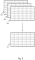
- Figure 1 shows an example of how the data in the point cloud may be stored in memory.
- the data is stored in the form of a two-dimensional point cloud matrix 101 having N rows and M columns.
- the data tuple also includes an intensity value l ij for that point.
- the intensity values and their respective spatial coordinates together define the geometry of the external surfaces of the object under consideration.
- the points can be rendered in three dimensions so as to provide a 3D representation of the object.
- the point cloud data may be computed from one or more two-dimensional images of the object as acquired using a 2D sensor array.
- the elements in the point cloud matrix may be mapped to pixel elements in the sensor array.
- the i and j indices may indicate the position of the respective pixel element in the sensor array.
- the ⁇ x ij y ij , z ij ⁇ coordinates may then define the position in space of a point as seen in that pixel in one or more of the two-dimensional images.
- the signal-to-noise ratio (SNR) in the final 3D image will be determined in part by the dynamic range of the sensor used to capture the image data. If the signal strength received from different points on the object is likely to vary considerably - because the object's surface contains a number of very bright and very dark regions, for example - then a balance must be struck between (i) maximizing the illumination intensity and/or sensor exposure time so as to ensure sufficient light is received from the darker regions of the object, and (ii) minimizing the illumination intensity and/or sensor exposure time to avoid saturating the sensor with signal from the brighter regions of the object. In order to address this problem, one proposed solution is to apply the concept of High Dynamic Range (HDR) Imaging to 3D imaging.
- HDR High Dynamic Range
- High Dynamic Range Imaging is an established technique for increasing dynamic range in light levels seen in digital images.
- the technique comprises capturing several images of the same scene with different exposure times, and post-processing the data from the images to produce a single HDR image of the scene.
- the images captured at longer exposure times permit capture of detail in darker areas of the scene, which cannot be discerned in images captured at shorter exposure times due to insufficient signal reaching the camera.
- the images captured at shorter exposure times meanwhile permit capture of detail in brighter areas of the scene, which cannot be discerned in the images captured at longer exposure times due to camera saturation.
- By post-processing these images using a suitable HDR algorithm it is possible to obtain a single, high definition image in which the elements of detail are visible across both light and dark regions of the image.
- HDR imaging The principles of HDR imaging are, broadly speaking, applicable to 3D imaging in the same way as conventional 2D imaging.
- Figure 2 shows, schematically, an example of how this might be implemented.
- the image data sets comprise 3D image data, rather than 2D image data, i.e. the image data sets specify the three-dimensional positions of points in the scene being looked at.
- Each image data set can be stored in the form of a respective point cloud matrix 201a, 201b, 201c.
- the point cloud matrices can then be merged into a single point cloud matrix 203 from which the 3D HDR image can be rendered.
- 3D HDR imaging does, however, pose additional challenges compared to 2D HDR imaging.
- One problem is that, in contrast to 2D imaging, an additional step of computation is required in order to obtain the three-dimensional coordinates of each point; the effect of any shortfall in SNR in the acquired image data may be compounded by this additional computation, significantly influencing the accuracy with which the 3D coordinates of each point in the output image are calculated. It is also difficult to identify appropriate exposure settings for capturing each set of image data to be used in generating the final 3D image.
- US2017/0118456 A1 discloses a method for determining the optimal exposure time and the number of exposures in a structured light-based 3D camera system.
- US2018/0176440 A1 discloses a method for controlling structured-light-based exposure conditions, involving determining optimal exposure condition, and calculating stereo image of object according to image group corresponding to optimal exposure condition.
- US2009/0185800 A1 discloses a method and system for determining an optimal exposure of a structured light based 3D camera.
- the present invention provides a method, an imaging system and a storage medium, as defined in the appended claims, for determining one or more groups of exposure settings to use in a 3D image acquisition process carried out with an imaging system.
- Embodiments described herein provide a means for obtaining 3D HDR images of an object.
- a 3D HDR image is obtained by capturing multiple sets of image data.
- the image data may be obtained using one of several techniques known in the art; these techniques may include, for example, structured light illumination, time of flight imaging and holographic techniques, as well as stereo imaging (both active and passive) and laser line triangulation.
- Each set of image data can be used to compute a respective input point cloud that specifies the three-dimensional coordinates of points on the object surface and their intensities.
- the information in each set of image data can be combined or merged in such a way as to provide a single output point cloud, from which a 3D image of the object can be rendered.
- the sets of image data may be acquired with different groups of exposure settings, such that the exposure of the imaging system differs for each set of image data.
- an "exposure setting" refers to a physical parameter of the imaging system that can be adjusted in order to vary the exposure of the system.
- a group of exposure settings may include parameters that directly affect the amount of light incident on the image sensor; examples of such parameters include one or more of the integration time of the camera/light sensor, the size of the camera/light sensor aperture and the intensity of light used to illuminate the scene or object.
- the group of exposure settings may also include the strength of a neutral density filter placed in the light path between the object and the camera/light sensor. The strength of the neutral density filter may be altered each time a new set of image data is acquired, so as to vary the amount of light reaching the camera or light sensor.
- parameters that affect the amount of light incident on the sensor may also be varied between exposures; these parameters may include the sensitivity of the camera or light sensor, for example, which can be varied by adjusting the gain applied to the device.
- only one of the exposure settings may be varied for each exposure, with the other exposure settings remaining constant each time a new set of image data is acquired.
- two or more of the settings may be varied in-between capturing each new set of image data.
- the image data is acquired with a greater exposure, this will maximize the signal that is detected from darker regions of the object or scene.
- the SNR for points in the darker regions can thereby be increased, allowing the spatial coordinates of those points to be computed with greater accuracy if compiling a point cloud from that set of image data.
- adjusting the exposure settings in such a way as to reduce the exposure makes it possible to maximize the signal that is captured from brighter regions of the object or scene without the camera or light sensor becoming saturated; thus, by reducing the exposure, it is possible to obtain a second set of image data in which the SNR for points in the brighter regions can be increased. In turn, it becomes possible to generate a second point cloud in which the spatial coordinates of points in those brighter regions can be computed with greater accuracy.
- the image data from these different exposures can then be combined in such a way as to ensure that the SNR in the output 3D image is enhanced for both the brighter and darker regions of the object.
- an additional "quality parameter" is evaluated for each point in each set of image data.
- Figure 3 shows an example of a point cloud matrix 301 as used in an embodiment.
- each element of the point cloud matrix in Figure 3 includes an additional value q ij .
- the value of the quality parameter q ij reflects the degree of uncertainty in the ⁇ x ij , y ij , z ij ⁇ coordinates of that respective point in the matrix.
- the value of the quality parameter provides a best estimate of the expected error in the ⁇ x ij , y ij , z ij ⁇ values at that point.
- the quality parameter may be defined in one of a number of different ways, depending on the particular technique used to capture the image data.
- a structured illumination approach is employed to acquire the image data from which an output point cloud is computed; in this case, the value of the quality parameter for a given point may, for example, be derived from a degree of contrast seen at that point on the object's surface as the light and dark fringes in the structured illumination pattern are projected on it.
- the quality parameter may be related to or derived from the difference in the amount of light detected from that point when illuminated by a light fringe in the illumination pattern and the amount of light detected from that point when illuminated by a dark fringe.
- a series of sinusoidally modulated intensity patterns may be projected on to the object, with the intensity patterns in the successive images being phase shifted with respect to one another; here, the quality parameter may be related to or derived from the intensity measured at each point, as each one of the intensity patterns is projected onto the object.
- the amplitude of the recovered signal at a given point may be compared with a measure of the ambient light in the system in order to derive a value of the quality parameter at that point.
- the quality parameter may be obtained by comparing and matching features identified in an image captured on a first camera with features identified in an image captured on a second camera, and determining a score for the quality of the match.
- ( r, c ) are the image pixel coordinates
- I 1 , I 2 is the stereo image pair
- ( x, y ) is the disparity that SAD is evaluated for
- ( A, B ) are the dimensions (in number of pixels) of the array over which the matching is carried out.
- each set of image data may be used to construct a respective input point cloud matrix. Then, for a given element ⁇ i, j ⁇ in the point cloud matrix used to construct the final 3D image, the set of coordinate values ⁇ x ij y ij , z ij ⁇ for that point may be derived by applying a respective weighting to each set of coordinate values ⁇ x ij y ij , z ij ⁇ at the same position ⁇ i, j ⁇ in the input point cloud matrices.
- the weighting applied in each matrix may be dependent on the value of the quality parameter q ij at that position in the respective matrix. In this way, the values ⁇ x ij y ij , z ij ⁇ in the output point cloud matrix can be biased towards values obtained from the image data set(s) having a higher SNR at the point in question.
- the set of coordinate values ⁇ x ij y ij , z ij ⁇ for the element ⁇ i, j ⁇ in the output point cloud matrix may be chosen by selecting the ⁇ x ij y ij , z ij ⁇ values from a single one of the input cloud matrices.
- the input point cloud matrix from which the values are selected may be the one having the highest value of q at that point, compared with the other input matrices.
- the set of coordinate values ⁇ x ij y ij , z ij ⁇ for that point may be derived by averaging the respective sets of coordinate values ⁇ x ij y ij , z ij ⁇ that lie at the position ⁇ i, j ⁇ in the input point cloud matrices.
- the value x ij in the output point cloud matrix may comprise an average of each one of the values x ij at the point ⁇ i, j ⁇ in the respective input point cloud matrices
- the value y ij in the output point cloud matrix may comprise an average of each one of the values y ij at the point ⁇ i, j ⁇ in the respective input point cloud matrices
- the value z ij in the output point cloud matrix may comprise an average of each one of the values z ij at the point ⁇ i, j ⁇ in the respective input point cloud matrices.
- the averaging may be subject to a threshold criterion, whereby only those values for which the associated q value is above a threshold are used in calculating the average value.
- the values ⁇ x ij y ij , z ij ⁇ in an element of one of the input point cloud matrices are accompanied by a q value that is below the threshold
- the values ⁇ x ij y ij , z ij ⁇ in that element may be disregarded for the purpose of calculating the values ⁇ x ij y ij , z ij ⁇ to be used in the output point cloud matrix.
- the thresholding criterion may also be applied in the other scenarios described above; for example, if computing the values ⁇ x ij y ij , z ij ⁇ for an element ⁇ i, j ⁇ in the output point cloud matrix by applying a respective weighting to the sets of coordinate values ⁇ x ij y ij , z ij ⁇ at the same position ⁇ i, j ⁇ in the point cloud matrices of the input matrices, a zero weighting may be applied to those sets of coordinate values ⁇ x ij y ij , z ij ⁇ that are accompanied by a q value that is below the threshold.
- the points of image data obtained from each exposure may be merged to generate a single merged set of image data.
- the values for each pixel in the merged set of data may then be based on the values for that pixel in one or more of the acquired sets of image data, with a bias towards those sets of image data for which the pixel in question is associated with a higher value of the quality parameter.
- FIG. 4 shows a flow-chart of steps carried out in embodiments described herein.
- a first step S401 a plurality of sets of 3D image data are acquired by an imaging system.
- Each set of 3D image data can be used to compute a respective input point cloud that defines the 3D coordinates of different points on the surface of an object being imaged, together with a value for the intensity or brightness level of the surface at each point.
- step S402 the value of a quality parameter is evaluated for the data associated with each point in each one of the respective input point clouds.
- the value of the quality parameter comprises a measure of the uncertainty in the three-dimensional co-ordinates at each point.
- the quality parameter may be computed as a function of the acquired intensity values that are used to calculate the spatial coordinates at each point in the respective input point clouds.
- a single output set of 3D image data is computed based on the image data contained in each one of the acquired sets of image data.
- the output set of image data defines values for the 3D coordinates of different points on the surface of the object being imaged, together with the intensity or brightness level of the surface at each point.
- the values for the 3D coordinates are computed by weighting the values for the 3D coordinates specified in the respective input point clouds, in accordance with their respective quality parameter values.
- the output image data set can then be used to render a 3D image of the object (step S404).
- FIG. 5A there is shown a schematic of a system suitable for capturing 3D images of an object 501 using structured light illumination.
- the system comprises a projector 503 and a camera 505.
- the projector is used to project a spatially varied 2D illumination pattern onto the object 40.
- the pattern itself comprises a series of light and dark fringes 507, 509.
- the pattern may be generated using a spatial light modulator, for example.
- the camera 505 is used to acquire a 2D image of the object as illuminated by the projector.
- Figure 5B shows a simplified diagram of the system geometry.
- the camera and projector are located a distance B apart.
- a point on the object that lies a distance D away from the camera and projector is located at an angle ⁇ c from the camera and ⁇ p from the projector.
- any variations in the surface topology of the object will cause the pattern of light and dark fringes, as detected by the camera, to become distorted.
- the distortion in the pattern will encode information about the 3D surface of the object, and can be used to deduce its surface topology.
- the 3D information can be recovered by capturing sequential images in which the object is illuminated with different patterns of light, and comparing the measured intensity for each pixel across the sequence of images.
- phase shifting is a well-known technique in which a sequence of sinusoidally modulated intensity patterns is projected onto the object, with each pattern being phase shifted with respect to the previous one.
- a 2D image of the illuminated object is captured each time the intensity pattern is changed. Variations in the surface topology of the object will give rise to a change in the phase of the intensity pattern as seen by the camera at different points across the surface.
- the data is output as a 2D array, in which each element maps to a respective one of the pixels of the camera, and defines the 3D spatial coordinates of a point as seen in that pixel.
- a Gray-coding technique may be used, or a combination of Gray-coding and phase shifting.
- the precise algorithms used to decode the 3D spatial information from the sequence of 2D images will vary depending on the specific illumination patterns and the way in which those patterns are varied across the sequence of images; further information on algorithms for recovering the depth information using these and other techniques is available in the publication " Structured light projection for accurate 3D shape determination" (O. Skotheim and F. Couweleers, ICEM12 - 12th International Conference on Experimental Mechanics 29 August - 2 September, 2004, Politecnico di Bari, Italy ).
- the 3D spatial information in the object is computed by considering the variation in intensities at each point on the object as the illumination pattern changes and the points are exposed to light and dark regions of the pattern.
- the projector is used to project a series of both Gray-code and phase-shifted patterns onto the object.
- the projector is used to project a series of both Gray-code and phase-shifted patterns onto the object.
- the images captured at the camera can be processed in order to determine, for each camera pixel, the corresponding projector pixel coordinate. In effect, a determination can be made as to which projector pixel a particular camera pixel is "looking at”. Moreover, by combining the image data received from the Gray-code patterns and phase shifted patterns, the projector pixel coordinate can be determined with higher resolution than the projector pixels themselves.
- the above methodology can be understood as follows. First, by choosing a number of N Gray code patterns, and setting the number of sinusoidal fringes in the phase shifting patterns to 2 N , the fringes can be aligned with the binary transitions in the sequence of N Gray code patterns.
- the resulting Gray code words, GC( i,j ) and the values obtained for the phase, ⁇ ( i,j ) can be combined to form a set of "GCPS" values that describe the absolute fringe position in each position in the field of view.
- the GCPS values can in turn be used to determine the projector pixel coordinates by performing a scaling of the values from a minimum/maximum of the code to the width ( w p ) and height ( h p ) of the projector image; in effect, one is able to measure the "fringe displacement" by estimating the phase of the sine patterns in every pixel in the camera.
- GC v ( i,j ) is the result of the Gray code measurements
- ⁇ ( i,j ) is a result of the phase stepping measurements, both performed with vertical fringes.
- those values can be used to obtain the ⁇ x,y,z ⁇ coordinates of points on the object being imaged; specifically, for a given camera pixel p, which is established to be receiving light from a point on the projector g, a position estimate E of a point on the object having coordinates ⁇ x ij y ij , z ij ⁇ can be derived by using known triangulation methods, akin to those used for stereo vision, taking into consideration the lens parameters, distance between the camera and projector etc.
- each GCPS value will be largely influenced by the amplitude of the recovered signal and to a lesser degree the presence of ambient light.
- the uncertainty in the GCPS value is typically fairly constant until the amplitude of the received signal drops beneath a certain level, after which the uncertainty increases nearly exponentially; this means that the measured amplitude and ambient light can be translated through a pre-established model into an expected measurement uncertainty of the GCPS value - an example is provided in Figure 6 , which shows the standard deviation (std) in the GCPS value as a function of intensity.
- the extent of contrast at a particular point may be limited by the need to accommodate a large range of intensities across the surface of the object; if the surface of the object itself comprises a number of bright and dark regions, then given the finite dynamic range of the camera, it may not be possible to maximize the signal recovered from dark regions of the object's surface without also incurring saturation effects where brighter regions of the object are exposed to the brighter fringes in the illumination pattern. It follows that it may not be possible to optimize the contrast in the intensities seen at every point on the surface in a single exposure (in this context, an "exposure” will be understood to refer to the capture of a sequence of 2D images from which a respective point cloud can be computed).
- a number of exposures are taken using different settings.
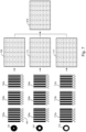
- An example of this is shown pictorially in Figure 7 .
- a first sequence of 2D images is captured using a first set of exposure settings.
- the exposure settings are varied by altering the relative size of the camera aperture, although it will be appreciated that the exposure settings may also be varied by adjusting one or more other parameters of the imaging system.
- the circle 701 shows the relative size of the camera aperture as used to capture the first sequence of images, and the patterns 703a, 703b, 703c show the illumination patterns that are projected onto the object when capturing the respective images in the first sequence of images.
- each illumination pattern 703a, 703b, 703c comprises a sinusoidally modulated intensity pattern in which a series of alternatively light and dark fringes are projected on to the object.
- the phase of the pattern across the field of view is illustrated schematically by the wave immediately beneath each pattern, with the dark fringes in the pattern corresponding to the troughs in the wave, and the bright fringes corresponding to the peaks in the wave.
- the illumination patterns in the successive images are phase shifted with respect to one another, with the positions of the bright and dark fringes in each pattern being translated with respect to one another.
- a suitable algorithm is used to compare the intensities of light in the same pixel across the sequence of 2D images, in order to compute the depth information at that point.
- the three-dimensional spatial information is then stored, together with the intensity value for each point, in a first point cloud matrix 705.
- each element in the point cloud matrix 705 includes a value for the quality parameter q, as shown in Figure 3 earlier.
- the value q is determined based on the standard deviation of the observed intensities in the respective camera pixel I n (i,j) seen as the three different illumination patterns 703a, 703b, 703c are projected on the object.
- the value q is determined based on the difference between the maximum value of intensity and minimum intensity in that pixel across the sequence of images. In this way, the quality parameter defines a measure of the contrast seen in each pixel across the sequence of images.
- the exposure settings are adjusted by expanding the size of the camera aperture, as reflected by the circle 707, thereby increasing the amount of light from the object that will reach the camera.
- a second sequence of 2D images is captured, with the illumination patterns 709a, 709b, 709c again being varied for each image in the sequence.
- the second sequence of 2D images is used to compute a second input 3D image point cloud 711 that records the depth information for each element, together with an intensity value and a value for the quality parameter q.
- the degree of contrast seen in a given pixel element ⁇ i, j ⁇ will vary across the two sequences of images; for example, the difference between the maximum intensity level and minimum intensity level detected in a given pixel element ⁇ i, j ⁇ will vary between the two sets of images. Accordingly, the values of q recorded in the first point cloud matrix 705 will likely differ from the values of q in the second point cloud matrix 711.
- the exposure settings are further adjusted by expanding the size of the camera aperture as shown by circle 713.
- a third sequence of 2D images is captured on the camera, with the illumination patterns 715a, 715b, 715c being projected onto the object.
- the third sequence of 2D images is used to compute a third input 3D image point cloud matrix 717, which again records the depth information for each element, together with an intensity value and a value for the quality parameter q.
- the difference in exposure between the second sequence of images and the third sequence of images means that it is likely that the degree of contrast seen in the same pixel element ⁇ i, j ⁇ will vary across the second and third sequences of images.
- the values of q recorded in the third point cloud matrix 717 will likely differ from both the first point cloud matrix 705 and the second point cloud matrix 711.
- the method proceeds by using the data in the respective point cloud matrices to compile a single output point cloud matrix 719, which can then be used to render a 3D representation of the object.
- the exposure was varied by increasing the size of the camera aperture in-between capturing each sequence of images, it will be readily understood that this is not the only means by which the exposure may be varied - other examples of ways in which the exposure may be varied include increasing the illumination intensity, increasing the camera integration time, increasing the camera sensitivity or gain, or by varying the strength of an neutral density filter placed in the optical path between the object and the camera.
- the output point cloud may be generated without the need to construct the individual point clouds for each set of image data.
- the values for the quality parameter associated with the pixels in each respective set of image data may be deduced from the signal levels detected in those pixels, as well as the amount of ambient light incident on the image sensor.
- embodiments as described herein can help to compensate for the limits in dynamic range of the camera, providing an enhanced signal to noise ratio for both darker and brighter points on the object surface. In so doing, embodiments can help to ensure that useable data is captured from areas that would, if using conventional methods of 3D surface imaging, be either completely missing from the final image or else dominated by noise, and can ensure that the surface topography of the object is mapped with greater accuracy compared with such conventional methods of 3D surface imaging.
- the camera sensor is imaging in grayscale; that is, a single intensity value is measured in each pixel, relating to the total light level incident on the sensor.
- the camera sensor may comprise an RGB sensor in which a Bayer mask is used to resolve the incident light into red, green and blue channels; in other embodiments, the camera sensor may comprise a three-CCD device in which three separate CCD sensors are used to collect the respective red, blue and green light signals.
- the point cloud matrices will be acquired in the same manner as in the above described embodiments, but within each matrix element, the intensity values I ij will be decomposed into the three colour intensities r ij , g ij , b ij .
- Figure 8 shows an example of such a point cloud matrix.
- the data used for rendering the final 3D image may be obtained by varying one or more exposure settings, including the illumination intensity, camera integration time (exposure time), increasing the camera sensitivity or gain, or by varying the strength of an neutral density filter placed in the optical path between the object and the camera, for example.
- exposure settings including the illumination intensity, camera integration time (exposure time), increasing the camera sensitivity or gain, or by varying the strength of an neutral density filter placed in the optical path between the object and the camera, for example.
- 3D measurement systems employing active illumination differ from regular cameras in that the amount of ambient light highly influences the dynamic range of the system if a desired maximum noise level is to be achieved.
- active illumination e.g. structured light, laser triangulation, time-of-flight
- Finding good exposure sets manually is a complex endeavour, as they require the user to have a complete mental model of the camera and its parameter sets.
- a target in terms of the value of the quality parameter to be obtained for pixels in the final 3D image, where that target is to be achieved subject to one or more imaging constraints.
- the goal is to try to optimize the final 3D image in terms of noise, whilst imposing one or more constraints ("costs") such as a maximum total exposure time, or total illumination power, for example.
- E Cost f 1 (exposure time)+f 2 (aperture size)+f 3 (neural density filter strength) +f 4 (illumination intensity)+...
- the functions ⁇ f 1 , f 2 , ... f n ⁇ define how the cost of the exposure varies with each respective parameter.
- the functions can be user-defined and effectively define the "downside" to the user in varying each parameter. As an example, if it is desirable to capture a 3D image in a very short space of time, then the user may apportion a high cost to exposure time. In another example, if the user is not time-limited, but wishes to keep the overall power usage to a minimum, they may apportion a high cost to illumination intensity.
- the value of E Cost can be used to provide a constraint in determining the optimum exposure settings for a given acquisition.
- E value serves to incorporate numerous effects that will affect how much signal is received by the camera, and thus the quality of each individual pixel in the system.
- E value can also be extended such that it returns two exposure values - one indicating the exposure value for the ambient light ( E ambient ) and one indicating the exposure value for the projected light ( E amplitude ).
- the relationship between each pair of functions defines the extent to which modifying one parameter will alter the amount of light incident on the camera, relative to modifying the other parameter.
- the step of doubling the exposure time may be equivalent to doubling the aperture size.
- the step of doubling the aperture size may be equivalent to reducing the neural density filter strength by a factor of 4.
- the functions ⁇ e 1 , e 2 , ... e n ⁇ may be defined so as to take these relationships into consideration.
- the functions ⁇ e 1 , e 2 , ... e n ⁇ and the relationships between them may be determined empirically offline by experiment. Knowledge of the relationships between these functions is useful because it can allow one to translate a change in one parameter value to other parameter values; for example, in the event that one is seeking to achieve a particular value for E value , and is able to determine a change in exposure time that will achieve that E value , it becomes possible to translate that change in exposure time into a change in the size of the aperture that will then have the same effect in terms of E value .
- this is advantageous because it can simplify the determination of the exposure settings for an acquisition by focusing on one parameter only (typically, the exposure time), and then translating the change(s) in exposure time into values of the other parameters according to the user's particular needs (e.g. a desire to minimize overall exposure time versus a desire to minimize aperture size etc.).
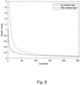
- Contrast indicates the amplitude/signal level of the active illumination employed by the camera system.
- the ambient light also influences the amount of light incident in the camera.
- the contrast is typically related to how much light is collected; as an example, doubling the exposure time is likely to double the contrast (and the ambient light).
- a certain value e.g. 50
- the measurement noise does not improve significantly with contrast.
- there is a fixed limit on what level of noise that can be tolerated e.g. 0.15 mm.
- exposures with contrast exceeding 40 could be considered to be "good enough”.
- the minimum contrast that can be tolerated also depends on the amount of ambient light present.
- ⁇ SL D 2 B si n ⁇ c sin ⁇ p FOV ⁇ max A + 2 C A
- D is the distance to the point being measured
- B is the camera-projector baseline
- ⁇ c and ⁇ p are the camera angle and projector angle, respectively.
- the value FOV is the field-of-view of the projector
- ⁇ max is the number of sine waves projected
- A is the amplitude of the observed sinewaves
- C is the fixed light signal received i.e. the ambient illumination + DC level of the emitted sine wave ( Bouquet, G., et al, "Design tool for TOF and SL based 3D cameras," Opt. Express 25, 27758-27769 (2017 )).
- B and FOV can be considered to be constants.
- A' ( p ) indicates the measured amplitude of a point p in the image
- C' ( p ) indicates the measured ambient light of the point p
- A* ( p ) is the exposure time independent amplitude of the point p
- C* ( p ) is the exposure time independent ambient light of the point p .
- ⁇ SL D 2 B sin ⁇ c sin ⁇ p FOV ⁇ max v + p + v ⁇ p v + p ⁇ v ⁇ p
- the quality parameter q 1 ⁇ SL .
- the desired outcome for q > q min can then be reformulated as ⁇ SL ⁇ ⁇ max .
- t min the minimum time that is required for sufficient exposure of that point on the object. It can be seen that the necessary t min depends not only on ambient light, but also the distance to object D and the position in scene as determined by the angles ⁇ c and ⁇ p . Depending on the implementation, these variables can be kept constant or reflect the actual perpixel data.
- the values of t min and t max for each pixel can be determined in a number of ways.
- the values are predicted from captured images as follows.
- I Init in order to quickly evaluate the amount of well-exposed pixels using exposure times from a candidate exposure taken from I Init we can use the following histogram-based approach. Given one or more images from I Init , we compute t min and t max for each pixel. We assume that I Init covers the whole dynamic range of the scene (typically around 7 stops) so that we can estimate the values of t min and t max for most of the pixels. For each pixel p, there could be several images I good p ⁇ I init which give good estimates for t min and t max for p . We compute these values by either picking some I from I good p or by averaging t min and t max from the whole set I good p .
- FIG. 10 An example of such a histogram is shown in Figure 10 .
- the x -axis represents t min ⁇ (0, 500) and the y- axis represents t max ⁇ (0, 500).
- H c x y ⁇ x ′ ⁇ x , y ′ ⁇ y H x y
- Figure 12 shows the results after each round in the algorithm, with each row showing one cycle in the while-loop.
- G is a binary image that is true for all pixels that are well exposed for the exposures contained in E opt .
- the initial image for G (image 1) is completely black since no pixels are known to have an acceptable value of q.
- the first exposure is selected for the scene with the maximum number of good pixels ( q > q min ) (see image 2).
- This provides an updated G (image 3).
- the updated image G is used as a basis, and a new E is selected as being the one that provides the maximum amount of additional well-exposed pixels. This then results in a further updated image for G.
- the algorithm will run until the sum of costs for the chosen set of exposures exceeds E cost max instead of until the sum of exposure times exceeds T max .
- E cost max instead of until the sum of exposure times exceeds T max .
- the algorithm will run until the sum of costs for the chosen set of exposures exceeds E cost max instead of until the sum of exposure times exceeds T max .
- the value E value for that group of exposure settings can be determined, and use this to translate to / generate one or more alternative candidate groups of exposure settings for which the value of E value is the same; this can be achieved by considering the functions ⁇ e 1 , e 2 , ... e n ⁇ as discussed earlier.
- These two alternatives should then provide similar outcomes in terms of the light that is collected from light and dark regions of the object being imaged.
- the two alternatives may have very different costs depending on whether the user places greater importance on keeping the overall exposure time as short as possible, or keeping the aperture size as small as possible (in other words, depending on the functions f 1 and f 2 in E Cost ) .
- the greedy algorithm can be easily modified to meet the second target i.e. to find a set of exposure settings for each image that will minimize the total exposure cost across the sequence of exposures, whilst ensuring that a threshold number of pixels in the final 3D image will have a quality parameter value q(p) > q min .
- the partition For each integer k, the partition results in a group of subsets of T ⁇ with total time t ⁇ k . Then, all subsets with a total time ⁇ T max corresponds to partitioning of all integers k ⁇ k max where k max is a mapped value of t ⁇ i closest to T max .
- the partitioning can be generated in a bottom-up manner or recursively. As an example, in Python code, one can use the following sequence of commands to generate the subsets recursively:
- the candidate groups of exposure settings are determined offline, such that each group of exposure settings to be used in the 3D image acquisition process is determined prior to acquiring the respective sets of image data.
- the 3D image acquisition process is carried out iteratively, by determining in each iteration, a next best group of exposure settings to use and then capturing a set of image data with that group of exposure settings.
- one or more new candidate groups of exposure settings are considered and a single one of the candidate groups of exposure settings selected for use in acquiring the next set of image data.
- a probabilistic model can be used to estimate the number of well-exposed pixels given a set of exposures that has already taken place.
- Figure 13 sets out a general framework for the above-described online approach with examples of possible algorithms for choosing candidate times and estimated the expected number of pixels with an acceptable value for the quality parameter.
- E ⁇ ( t i , I ( t i ) ⁇ as a set of current exposure times along with images.
- the algorithm uses ComputeExpectedNum to estimate the expected number of pixels for which ⁇ ( p ) ⁇ ⁇ max given an exposure time t and previous exposures E. It uses the probabilistic model described above, and can be extended by estimating ⁇ i using machine learning techniques (for example, by using values of neighbourhood pixels with a convolutional neural network CNN).
- the procedure estimates the probability for each pixel based on which one of the above categories the pixel falls into:
- the algorithm will run until the sum of costs for the set of exposures exceeds E cost max instead of until the sum of exposure times exceeds T max .
- the algorithm terminates once the ratio between expected increase in number of new good pixels (the return value from ComputeExpectedNum) versus the exposure cost of the selected exposure falls below a threshold.
- this can be translated to a set of aperture sizes ⁇ a 1 , a 2 , ..., a n ⁇ or combinations of both these parameters ⁇ t 1 , a 1 ⁇ , ⁇ t 2 , a 2 ⁇ ..., ⁇ t n , a n ⁇ by considering the respective functions ⁇ e 1 , e 2 , ..., e n ⁇ associated with the exposure time and aperture size whilst minimizing their respective costs ⁇ f 1 , f 2 , ... , f n ⁇ . Accordingly, although the algorithms described herein focus on exposure time, the determination of different exposure times can act as a proxy for determining the settings for other parameters that affect the amount of light incident on the camera.
- N ph is the total signal level received (the sum of amplitude A and ambient light C )
- ⁇ response is the time response of the system
- c is the speed of light
- m is the number of samples performed.
- N ph can be replaced by the signal to noise ratio (SNR) when including contribution from dark noise and ambient noise.
- SNR signal to noise ratio
- ⁇ response will usually be a constant (dictated by the characteristics of the components).
- embodiments described herein provide a means for rendering a high SNR 3D image of a scene or object.
- a plurality of image acquisitions with different exposure settings and merging the data from those sets of image data to form a single point cloud in which the signal to noise ratio is maximised for each point it is possible to accommodate large variations in the amount of light available from different points in the scene.
- embodiments provide a means for determining a set of exposure settings to use in acquiring each image, in a way that will maximise the signal to noise ratio in the final 3D image whilst satisfying one or more constraints on time, depth of focus, illumination power, etc.
- implementations of the subject matter and the operations described in this specification can be realized in digital electronic circuitry, or in computer software, firmware, or hardware, including the structures disclosed in this specification and their structural equivalents, or in combinations of one or more of them.
- Implementations of the subject matter described in this specification can be realized using one or more computer programs, i.e., one or more modules of computer program instructions, encoded on computer storage medium for execution by, or to control the operation of, data processing apparatus.
- the program instructions can be encoded on an artificially generated propagated signal, e.g., a machine-generated electrical, optical, or electromagnetic signal that is generated to encode information for transmission to suitable receiver apparatus for execution by a data processing apparatus.
- a computer storage medium can be, or be included in, a computer-readable storage device, a computer-readable storage substrate, a random or serial access memory array or device, or a combination of one or more of them. Moreover, while a computer storage medium is not a propagated signal, a computer storage medium can be a source or destination of computer program instructions encoded in an artificially generated propagated signal. The computer storage medium can also be, or be included in, one or more separate physical components or media (e.g., multiple CDs, disks, or other storage devices).
Landscapes
- Engineering & Computer Science (AREA)
- Multimedia (AREA)
- Signal Processing (AREA)
- Physics & Mathematics (AREA)
- General Physics & Mathematics (AREA)
- Theoretical Computer Science (AREA)
- Electromagnetism (AREA)
- Computer Vision & Pattern Recognition (AREA)
- Length Measuring Devices By Optical Means (AREA)
- Exposure Control For Cameras (AREA)
- Stereoscopic And Panoramic Photography (AREA)
- Testing, Inspecting, Measuring Of Stereoscopic Televisions And Televisions (AREA)
- Studio Devices (AREA)
- Image Processing (AREA)
Claims (15)
- Procédé pour déterminer un ou plusieurs groupes de réglages d'exposition à utiliser lors dans un processus d'acquisition d'images 3D mis en oeuvre avec un système d'imagerie, le système d'imagerie comprenant un capteur d'images et le processus d'acquisition d'images 3D comprenant la capture d'un ou de plusieurs ensembles de données d'image sur le capteur d'images en utilisant les groupes respectifs de réglages d'exposition, dans lequel les un ou plusieurs ensembles de données d'image sont tels qu'ils permettent la génération d'un ou de plusieurs nuages de points 3D définissant les coordonnées tridimensionnelles de points sur lalles surface(s) d'un ou de plusieurs objets qui sont imagés, chaque groupe de réglages d'exposition incluant un temps d'exposition à utiliser lors de la capture de l'un respectif des ensembles de données d'image, le procédé comprenant :(i) l'identification, en utilisant des données d'image capturées sur le capteur d'images, d'un ou de plusieurs groupes candidats de réglages d'exposition ;(ii) pour chaque groupe candidat de réglages d'exposition :la détermination d'une quantité de signal susceptible d'être reçue dans différents pixels du capteur d'images dans l'éventualité où le groupe candidat de réglages d'exposition est utilisé pour capturer un ensemble de données d'image pour une utilisation dans le processus d'acquisition d'images 3D,la détermination, sur la base de la quantité de signal susceptible d'être reçue dans les différents pixels, de si oui ou non les pixels respectifs seraient des pixels bien exposés si le groupe candidat de réglages d'exposition est utilisé, dans lequel un pixel bien exposé est un pixel pour lequel la valeur d'un paramètre de qualité associé à ce pixel est au-delà d'un seuil, dans lequel la valeur du paramètre de qualité pour un pixel reflète un degré d'incertitude qui serait présent dans les coordonnées tridimensionnelles d'un point dans un nuage de points associé à ce pixel, dans l'éventualité où le nuage de points serait généré en utilisant l'ensemble de données d'image capturé avec le groupe candidat de réglages d'exposition ; et(iii) la sélection, parmi les un ou plusieurs groupes candidats de réglages d'exposition, d'un ou de plusieurs groupes de réglages d'exposition à utiliser pour le processus d'acquisition d'images 3D, caractérisé en ce que la sélection est telle qu'elle maximise le nombre de pixels dans l'ensemble N, dans lequel un pixel appartiendra à l'ensemble N s'il y a au moins un groupe sélectionné de réglages d'exposition pour lequel le pixel est déterminé comme étant un pixel bien exposé,
dans lequel la sélection est mise en oeuvre en étant soumise à la contrainte consistant en ce qu'une somme des temps d'exposition pour le/les groupe(s) sélectionné(s) de réglages d'exposition est en deçà d'un seuil prédéfini. - Procédé selon la revendication précédente, dans lequel, pour un ou plusieurs des groupes candidats de réglages d'exposition, l'étape de détermination d'une quantité de signal susceptible d'être reçue dans différents pixels du capteur d'images dans l'éventualité où le groupe candidat de réglages d'exposition est utilisé pour capturer un ensemble de données d'image comprend la capture d'un ensemble de données d'image avec le groupe candidat de réglages d'exposition.
- Procédé selon la revendication 2, dans lequel l'ensemble/les ensembles de données d'image capturés lors de l'utilisation des un ou plusieurs groupes candidats de réglages d'exposition sont utilisés pour identifier un ou plusieurs autres groupes candidats de réglages d'exposition.
- Procédé selon la revendication 1, dans lequel les étapes (i) à (iii) sont répétées sur une ou plusieurs itérations, dans lequel, pour chaque itération :un unique groupe des groupes candidats de réglages d'exposition identifiés lors de cette itération est sélectionné ; etle nombre de pixels dans l'ensemble N est maximisé, en étant soumis à la contrainte consistant en ce que la somme du temps d'exposition pour le groupe de réglages d'exposition sélectionné lors de l'itération courante et pour les groupes de réglages d'exposition sélectionnés lors de toutes les itérations précédentes est en deçà du seuil prédéfini.
- Procédé selon la revendication 4, dans lequel, pour chaque itération, le groupe sélectionné de réglages d'exposition est utilisé pour capturer un ensemble de données d'imagerie avec le système d'imagerie ;
dans lequel, pour chaque itération à partir de la seconde itération, l'ensemble de données d'image capturé lors de l'itération précédente est utilisé lors de la détermination des groupes candidats de réglages d'exposition pour l'itération courante. - Procédé selon la revendication 5, dans lequel l'étape de détermination de si oui ou non des pixels respectifs seraient des pixels bien exposés si un groupe candidat de réglages d'exposition est utilisé comprend la détermination d'une probabilité que les pixels respectifs soient bien exposés, la probabilité étant déterminée sur la base de la quantité de signal reçue dans ces pixels lors d'itérations précédentes du procédé.
- Procédé selon l'une quelconque des revendications précédentes, dans lequel l'étape d'identification d'un ou de plusieurs groupes candidats de réglages d'exposition comprend la détermination, pour un ou plusieurs pixels du capteur d'images, d'une plage de temps d'exposition pour laquelle le pixel est susceptible d'être un pixel bien exposé et/ou
dans lequel la valeur du paramètre de qualité associé à un pixel est déterminée sur la base de la quantité de lumière ambiante dans la scène qui est imagée. - Procédé selon l'une quelconque des revendications précédentes, dans lequel chaque groupe de réglages d'exposition comprend une ou plusieurs parmi :la dimension d'un diaphragme d'ouverture dans le chemin entre l'objet et le capteur ;une intensité de la lumière utilisée pour éclairer l'objet ; etla puissance d'un filtre ND placé dans le chemin de la lumière entre l'objet et le capteur.
- Procédé selon l'une quelconque des revendications précédentes, dans lequel le système d'imagerie est un système d'imagerie optique comprenant un ou plusieurs capteurs de lumière ; et
en option, dans lequel le système d'imagerie inclut une ou plusieurs sources de lumière qui sont utilisées pour éclairer l'objet qui est imagé. - Procédé selon l'une quelconque des revendications précédentes, dans lequel les données d'image dans chaque ensemble de données d'image comprennent une ou plusieurs images 2D de l'objet telles que capturées sur le capteur et/ou dans lequel chaque ensemble de données d'image comprend une information de couleur.
- Procédé selon l'une quelconque des revendications précédentes, dans lequel le système d'imagerie est un système d'imagerie qui utilise un éclairage structuré pour obtenir chaque ensemble de données d'image.
- Procédé selon la revendication 11, dans lequel chaque ensemble de données d'image comprend une séquence d'images 2D de l'objet telles que capturées sur le capteur de lumière, chaque image 2D dans la séquence étant capturée en utilisant un motif d'éclairage différent ; et
en option, dans lequel chaque ensemble de données d'image comprend une séquence d'images codées par code de Gray et une séquence d'images déphasées. - Procédé pour générer une image 3D d'un ou de plusieurs objets en utilisant un système d'imagerie comprenant un capteur d'images, le procédé comprenant :la capture, sur le capteur d'images, d'un ou de plusieurs ensembles de données d'image en utilisant des groupes respectifs de réglages d'exposition, les ensembles de données d'image étant tels qu'ils permettent la génération d'un ou de plusieurs nuages de points 3D définissant les coordonnées tridimensionnelles de points sur la/les surface(s) des un ou plusieurs objets, chaque groupe de réglages d'exposition incluant un temps d'exposition à utiliser lors de la capture de l'un respectif des ensembles de données d'image ; etla construction d'un nuage de points 3D en utilisant les données en provenance d'un ou de plusieurs des ensembles capturés de données d'image ;dans lequel les réglages d'exposition utilisés pour capturer chaque ensemble de données d'image sont déterminés en utilisant un procédé selon l'une quelconque des revendications précédentes.
- Système d'imagerie pour réaliser un processus d'acquisition d'images 3D en capturant un ou plusieurs ensembles de données d'image avec un ou plusieurs groupes de réglages d'exposition, les un ou plusieurs ensembles de données d'image étant tels qu'ils permettent la génération d'un ou de plusieurs nuages de points 3D définissant les coordonnées tridimensionnelles de points sur la surface d'un ou de plusieurs objets qui sont imagés, le système d'imagerie comprenant un moyen de traitement et un capteur d'images pour capturer les un ou plusieurs ensembles de données d'image, le système d'imagerie étant configuré pour déterminer les un ou plusieurs groupes de réglages d'exposition à utiliser pour le processus d'acquisition d'images 3D en mettant en oeuvre un procédé selon l'une quelconque des revendications 1 à 13.
- Support de stockage lisible par ordinateur comprenant un code exécutable par ordinateur pour amener le système d'imagerie selon la revendication 14 à mettre en oeuvre un procédé selon l'une quelconque des revendications précédentes 1 à 13.
Applications Claiming Priority (2)
| Application Number | Priority Date | Filing Date | Title |
|---|---|---|---|
| GB1908935.8A GB2584907A (en) | 2019-06-21 | 2019-06-21 | Method for determining one or more groups of exposure settings to use in a 3D image acquisition process |
| PCT/EP2020/067244 WO2020254657A1 (fr) | 2019-06-21 | 2020-06-19 | Procédé de détermination d'un ou plusieurs groupes de réglages d'exposition à utiliser dans un procédé d'acquisition d'image 3d |
Publications (3)
| Publication Number | Publication Date |
|---|---|
| EP3987764A1 EP3987764A1 (fr) | 2022-04-27 |
| EP3987764B1 true EP3987764B1 (fr) | 2024-05-08 |
| EP3987764C0 EP3987764C0 (fr) | 2024-05-08 |
Family
ID=67511617
Family Applications (1)
| Application Number | Title | Priority Date | Filing Date |
|---|---|---|---|
| EP20734006.8A Active EP3987764B1 (fr) | 2019-06-21 | 2020-06-19 | Procede pour determiner un ou plusieurs groupes de reglages d'exposition à utiliser dans un processus d'acquisition d'image 3d |
Country Status (7)
| Country | Link |
|---|---|
| US (1) | US12302003B2 (fr) |
| EP (1) | EP3987764B1 (fr) |
| JP (1) | JP7671991B2 (fr) |
| KR (1) | KR102836225B1 (fr) |
| CN (1) | CN114731373B (fr) |
| GB (1) | GB2584907A (fr) |
| WO (1) | WO2020254657A1 (fr) |
Families Citing this family (6)
| Publication number | Priority date | Publication date | Assignee | Title |
|---|---|---|---|---|
| FR3122276B1 (fr) * | 2021-04-26 | 2023-03-10 | Commissariat Energie Atomique | Traitement d'image destiné à une inférence intégrée |
| CN114363525B (zh) * | 2022-03-17 | 2022-06-28 | 杭州灵西机器人智能科技有限公司 | Hdr快速自动成像方法、结构光相机、电子设备和存储介质 |
| CN117176926A (zh) * | 2022-05-27 | 2023-12-05 | 苏州佳世达光电有限公司 | 三维影像产生方法及系统 |
| JP7593382B2 (ja) * | 2022-09-20 | 2024-12-03 | セイコーエプソン株式会社 | 表示方法、表示システム、及びプログラム |
| CN116124033B (zh) * | 2022-11-18 | 2025-11-25 | 无锡微视传感科技有限公司 | 一种基于结构光条纹的自动曝光控制方法 |
| CN120196213B (zh) * | 2025-03-24 | 2025-08-22 | 中国标准化研究院 | 基于数字标准人的数字人智能交互检测方法及系统 |
Family Cites Families (22)
| Publication number | Priority date | Publication date | Assignee | Title |
|---|---|---|---|---|
| CN100480625C (zh) | 2005-11-18 | 2009-04-22 | 北京航空航天大学 | 基于自适应正弦条纹投射的立体视觉检测系统 |
| JP2007271530A (ja) | 2006-03-31 | 2007-10-18 | Brother Ind Ltd | 3次元形状検出装置及び3次元形状検出方法 |
| US7940311B2 (en) * | 2007-10-03 | 2011-05-10 | Nokia Corporation | Multi-exposure pattern for enhancing dynamic range of images |
| KR100914961B1 (ko) * | 2008-01-23 | 2009-09-02 | 성균관대학교산학협력단 | 구조광 기반 3차원 카메라의 최적 노출 결정방법 및 시스템 |
| JP5789275B2 (ja) * | 2012-02-03 | 2015-10-07 | エーエスエムエル ネザーランズ ビー.ブイ. | 3dレジストプロファイルのシミュレーション用のリソグラフィモデル |
| US11263823B2 (en) * | 2012-02-24 | 2022-03-01 | Matterport, Inc. | Employing three-dimensional (3D) data predicted from two-dimensional (2D) images using neural networks for 3D modeling applications and other applications |
| JP2017059998A (ja) | 2015-09-16 | 2017-03-23 | キヤノン株式会社 | 画像処理装置およびその方法、並びに、撮像装置 |
| KR101737518B1 (ko) * | 2015-10-27 | 2017-05-18 | 성균관대학교산학협력단 | 구조광 기반 3차원 카메라의 최적 노출 시간 및 횟수 결정 방법과 시스템 |
| KR102120269B1 (ko) * | 2015-11-11 | 2020-06-08 | 후아웨이 테크놀러지 컴퍼니 리미티드 | 하이 다이내믹 레인지 비디오/이미징을 위한 노출 시간들의 세트를 축소시키기 위한 디바이스 및 방법 |
| US10453185B2 (en) * | 2015-11-12 | 2019-10-22 | Aquifi, Inc. | System and method for high dynamic range depth capture using multiple cameras |
| CN113532326B (zh) | 2016-02-29 | 2023-11-21 | 派克赛斯有限责任公司 | 用于辅助型3d扫描的系统和方法 |
| CN108616726A (zh) * | 2016-12-21 | 2018-10-02 | 光宝电子(广州)有限公司 | 基于结构光的曝光控制方法及曝光控制装置 |
| US10425599B2 (en) * | 2017-02-01 | 2019-09-24 | Omnivision Technologies, Inc. | Exposure selector for high-dynamic range imaging and associated method |
| JP6970551B2 (ja) * | 2017-07-31 | 2021-11-24 | 株式会社キーエンス | 形状測定装置及び形状測定方法 |
| KR101887945B1 (ko) * | 2017-08-10 | 2018-08-13 | 성균관대학교산학협력단 | 3d 카메라의 노출 시간 결정 방법 및 장치 |
| CN107894215B (zh) * | 2017-12-26 | 2020-05-08 | 东南大学 | 基于全自动曝光的高动态范围光栅投影三维测量方法 |
| US11592536B2 (en) * | 2018-01-10 | 2023-02-28 | Sony Semiconductor Solutions Corporation | Control of image capture |
| US20190243376A1 (en) * | 2018-02-05 | 2019-08-08 | Qualcomm Incorporated | Actively Complementing Exposure Settings for Autonomous Navigation |
| CN109087325B (zh) | 2018-07-20 | 2022-03-04 | 成都指码科技有限公司 | 一种基于单目视觉的直接法点云三维重建及尺度确定方法 |
| US10791277B2 (en) * | 2018-09-11 | 2020-09-29 | Cognex Corporation | Methods and apparatus for optimizing image acquisition of objects subject to illumination patterns |
| US11521371B2 (en) * | 2019-12-26 | 2022-12-06 | Woven Planet North America, Inc. | Systems and methods for semantic map-based adaptive auto-exposure |
| US11145076B1 (en) * | 2020-10-27 | 2021-10-12 | R-Go Robotics Ltd | Incorporation of semantic information in simultaneous localization and mapping |
-
2019
- 2019-06-21 GB GB1908935.8A patent/GB2584907A/en not_active Withdrawn
-
2020
- 2020-06-19 US US17/620,933 patent/US12302003B2/en active Active
- 2020-06-19 CN CN202080059570.1A patent/CN114731373B/zh active Active
- 2020-06-19 KR KR1020227002393A patent/KR102836225B1/ko active Active
- 2020-06-19 EP EP20734006.8A patent/EP3987764B1/fr active Active
- 2020-06-19 JP JP2021576112A patent/JP7671991B2/ja active Active
- 2020-06-19 WO PCT/EP2020/067244 patent/WO2020254657A1/fr not_active Ceased
Also Published As
| Publication number | Publication date |
|---|---|
| GB201908935D0 (en) | 2019-08-07 |
| KR20220024901A (ko) | 2022-03-03 |
| KR102836225B1 (ko) | 2025-07-18 |
| US20220329716A1 (en) | 2022-10-13 |
| US12302003B2 (en) | 2025-05-13 |
| EP3987764A1 (fr) | 2022-04-27 |
| EP3987764C0 (fr) | 2024-05-08 |
| CN114731373A (zh) | 2022-07-08 |
| JP7671991B2 (ja) | 2025-05-07 |
| JP2022537423A (ja) | 2022-08-25 |
| WO2020254657A1 (fr) | 2020-12-24 |
| CN114731373B (zh) | 2025-01-14 |
| GB2584907A (en) | 2020-12-23 |
Similar Documents
| Publication | Publication Date | Title |
|---|---|---|
| EP3987764B1 (fr) | Procede pour determiner un ou plusieurs groupes de reglages d'exposition à utiliser dans un processus d'acquisition d'image 3d | |
| EP3729367B1 (fr) | Procédé et système permettant de générer une image tridimensionnelle d'un objet | |
| EP3293698B1 (fr) | Appareil de mesure de temps de vol et procédé de traitement d'image permettant de réduire le flou d'une image de profondeur en son sein | |
| CA3040002C (fr) | Dispositif et procede d'obtention d'informations de distance a partir de vues | |
| CN109477710B (zh) | 基于点的结构化光系统的反射率图估计 | |
| US9420276B2 (en) | Calibration of light-field camera geometry via robust fitting | |
| US20170059305A1 (en) | Active illumination for enhanced depth map generation | |
| US20130083309A1 (en) | Apparatus and method to correct image | |
| US20170324950A1 (en) | Methods and apparatus for controlling light field capture | |
| US9818199B2 (en) | Method and apparatus for estimating depth of focused plenoptic data | |
| JP6867645B2 (ja) | 画像処理装置、方法、及びプログラム | |
| US20160245641A1 (en) | Projection transformations for depth estimation | |
| JP2017134561A (ja) | 画像処理装置、撮像装置および画像処理プログラム | |
| US10412328B2 (en) | Systems and methods for rolling shutter compensation using iterative process | |
| HK40043924B (en) | Method and apparatus for generating depth images, method for generating reference images, and electronic device | |
| HK40043924A (en) | Method and apparatus for generating depth images, method for generating reference images, and electronic device |
Legal Events
| Date | Code | Title | Description |
|---|---|---|---|
| STAA | Information on the status of an ep patent application or granted ep patent |
Free format text: STATUS: UNKNOWN |
|
| STAA | Information on the status of an ep patent application or granted ep patent |
Free format text: STATUS: THE INTERNATIONAL PUBLICATION HAS BEEN MADE |
|
| PUAI | Public reference made under article 153(3) epc to a published international application that has entered the european phase |
Free format text: ORIGINAL CODE: 0009012 |
|
| STAA | Information on the status of an ep patent application or granted ep patent |
Free format text: STATUS: REQUEST FOR EXAMINATION WAS MADE |
|
| 17P | Request for examination filed |
Effective date: 20211230 |
|
| AK | Designated contracting states |
Kind code of ref document: A1 Designated state(s): AL AT BE BG CH CY CZ DE DK EE ES FI FR GB GR HR HU IE IS IT LI LT LU LV MC MK MT NL NO PL PT RO RS SE SI SK SM TR |
|
| DAV | Request for validation of the european patent (deleted) | ||
| DAX | Request for extension of the european patent (deleted) | ||
| REG | Reference to a national code |
Ref country code: DE Ref legal event code: R079 Free format text: PREVIOUS MAIN CLASS: H04N0005235000 Ipc: H04N0013254000 Ref country code: DE Ref legal event code: R079 Ref document number: 602020030625 Country of ref document: DE Free format text: PREVIOUS MAIN CLASS: H04N0005235000 Ipc: H04N0013254000 |
|
| RIC1 | Information provided on ipc code assigned before grant |
Ipc: H04N 23/743 20230101ALN20230726BHEP Ipc: H04N 23/73 20230101ALN20230726BHEP Ipc: H04N 13/296 20180101ALI20230726BHEP Ipc: H04N 13/254 20180101AFI20230726BHEP |
|
| GRAP | Despatch of communication of intention to grant a patent |
Free format text: ORIGINAL CODE: EPIDOSNIGR1 |
|
| STAA | Information on the status of an ep patent application or granted ep patent |
Free format text: STATUS: GRANT OF PATENT IS INTENDED |
|
| INTG | Intention to grant announced |
Effective date: 20230922 |
|
| GRAS | Grant fee paid |
Free format text: ORIGINAL CODE: EPIDOSNIGR3 |
|
| GRAA | (expected) grant |
Free format text: ORIGINAL CODE: 0009210 |
|
| STAA | Information on the status of an ep patent application or granted ep patent |
Free format text: STATUS: THE PATENT HAS BEEN GRANTED |
|
| AK | Designated contracting states |
Kind code of ref document: B1 Designated state(s): AL AT BE BG CH CY CZ DE DK EE ES FI FR GB GR HR HU IE IS IT LI LT LU LV MC MK MT NL NO PL PT RO RS SE SI SK SM TR |
|
| REG | Reference to a national code |
Ref country code: GB Ref legal event code: FG4D |
|
| REG | Reference to a national code |
Ref country code: CH Ref legal event code: EP |
|
| REG | Reference to a national code |
Ref country code: DE Ref legal event code: R096 Ref document number: 602020030625 Country of ref document: DE |
|
| REG | Reference to a national code |
Ref country code: IE Ref legal event code: FG4D |
|
| U01 | Request for unitary effect filed |
Effective date: 20240606 |
|
| U07 | Unitary effect registered |
Designated state(s): AT BE BG DE DK EE FI FR IT LT LU LV MT NL PT SE SI Effective date: 20240620 |
|
| U20 | Renewal fee for the european patent with unitary effect paid |
Year of fee payment: 5 Effective date: 20240722 |
|
| PG25 | Lapsed in a contracting state [announced via postgrant information from national office to epo] |
Ref country code: IS Free format text: LAPSE BECAUSE OF FAILURE TO SUBMIT A TRANSLATION OF THE DESCRIPTION OR TO PAY THE FEE WITHIN THE PRESCRIBED TIME-LIMIT Effective date: 20240908 |
|
| PG25 | Lapsed in a contracting state [announced via postgrant information from national office to epo] |
Ref country code: HR Free format text: LAPSE BECAUSE OF FAILURE TO SUBMIT A TRANSLATION OF THE DESCRIPTION OR TO PAY THE FEE WITHIN THE PRESCRIBED TIME-LIMIT Effective date: 20240508 |
|
| PG25 | Lapsed in a contracting state [announced via postgrant information from national office to epo] |
Ref country code: GR Free format text: LAPSE BECAUSE OF FAILURE TO SUBMIT A TRANSLATION OF THE DESCRIPTION OR TO PAY THE FEE WITHIN THE PRESCRIBED TIME-LIMIT Effective date: 20240809 |
|
| PG25 | Lapsed in a contracting state [announced via postgrant information from national office to epo] |
Ref country code: ES Free format text: LAPSE BECAUSE OF FAILURE TO SUBMIT A TRANSLATION OF THE DESCRIPTION OR TO PAY THE FEE WITHIN THE PRESCRIBED TIME-LIMIT Effective date: 20240508 |
|
| PG25 | Lapsed in a contracting state [announced via postgrant information from national office to epo] |
Ref country code: PL Free format text: LAPSE BECAUSE OF FAILURE TO SUBMIT A TRANSLATION OF THE DESCRIPTION OR TO PAY THE FEE WITHIN THE PRESCRIBED TIME-LIMIT Effective date: 20240508 |
|
| PG25 | Lapsed in a contracting state [announced via postgrant information from national office to epo] |
Ref country code: PL Free format text: LAPSE BECAUSE OF FAILURE TO SUBMIT A TRANSLATION OF THE DESCRIPTION OR TO PAY THE FEE WITHIN THE PRESCRIBED TIME-LIMIT Effective date: 20240508 Ref country code: IS Free format text: LAPSE BECAUSE OF FAILURE TO SUBMIT A TRANSLATION OF THE DESCRIPTION OR TO PAY THE FEE WITHIN THE PRESCRIBED TIME-LIMIT Effective date: 20240908 Ref country code: HR Free format text: LAPSE BECAUSE OF FAILURE TO SUBMIT A TRANSLATION OF THE DESCRIPTION OR TO PAY THE FEE WITHIN THE PRESCRIBED TIME-LIMIT Effective date: 20240508 Ref country code: GR Free format text: LAPSE BECAUSE OF FAILURE TO SUBMIT A TRANSLATION OF THE DESCRIPTION OR TO PAY THE FEE WITHIN THE PRESCRIBED TIME-LIMIT Effective date: 20240809 Ref country code: ES Free format text: LAPSE BECAUSE OF FAILURE TO SUBMIT A TRANSLATION OF THE DESCRIPTION OR TO PAY THE FEE WITHIN THE PRESCRIBED TIME-LIMIT Effective date: 20240508 Ref country code: RS Free format text: LAPSE BECAUSE OF FAILURE TO SUBMIT A TRANSLATION OF THE DESCRIPTION OR TO PAY THE FEE WITHIN THE PRESCRIBED TIME-LIMIT Effective date: 20240808 |
|
| PG25 | Lapsed in a contracting state [announced via postgrant information from national office to epo] |
Ref country code: CZ Free format text: LAPSE BECAUSE OF FAILURE TO SUBMIT A TRANSLATION OF THE DESCRIPTION OR TO PAY THE FEE WITHIN THE PRESCRIBED TIME-LIMIT Effective date: 20240508 |
|
| PG25 | Lapsed in a contracting state [announced via postgrant information from national office to epo] |
Ref country code: SK Free format text: LAPSE BECAUSE OF FAILURE TO SUBMIT A TRANSLATION OF THE DESCRIPTION OR TO PAY THE FEE WITHIN THE PRESCRIBED TIME-LIMIT Effective date: 20240508 Ref country code: RO Free format text: LAPSE BECAUSE OF FAILURE TO SUBMIT A TRANSLATION OF THE DESCRIPTION OR TO PAY THE FEE WITHIN THE PRESCRIBED TIME-LIMIT Effective date: 20240508 |
|
| PG25 | Lapsed in a contracting state [announced via postgrant information from national office to epo] |
Ref country code: SM Free format text: LAPSE BECAUSE OF FAILURE TO SUBMIT A TRANSLATION OF THE DESCRIPTION OR TO PAY THE FEE WITHIN THE PRESCRIBED TIME-LIMIT Effective date: 20240508 |
|
| PG25 | Lapsed in a contracting state [announced via postgrant information from national office to epo] |
Ref country code: SM Free format text: LAPSE BECAUSE OF FAILURE TO SUBMIT A TRANSLATION OF THE DESCRIPTION OR TO PAY THE FEE WITHIN THE PRESCRIBED TIME-LIMIT Effective date: 20240508 Ref country code: SK Free format text: LAPSE BECAUSE OF FAILURE TO SUBMIT A TRANSLATION OF THE DESCRIPTION OR TO PAY THE FEE WITHIN THE PRESCRIBED TIME-LIMIT Effective date: 20240508 Ref country code: RO Free format text: LAPSE BECAUSE OF FAILURE TO SUBMIT A TRANSLATION OF THE DESCRIPTION OR TO PAY THE FEE WITHIN THE PRESCRIBED TIME-LIMIT Effective date: 20240508 Ref country code: CZ Free format text: LAPSE BECAUSE OF FAILURE TO SUBMIT A TRANSLATION OF THE DESCRIPTION OR TO PAY THE FEE WITHIN THE PRESCRIBED TIME-LIMIT Effective date: 20240508 |
|
| REG | Reference to a national code |
Ref country code: CH Ref legal event code: PL |
|
| PG25 | Lapsed in a contracting state [announced via postgrant information from national office to epo] |
Ref country code: MC Free format text: LAPSE BECAUSE OF FAILURE TO SUBMIT A TRANSLATION OF THE DESCRIPTION OR TO PAY THE FEE WITHIN THE PRESCRIBED TIME-LIMIT Effective date: 20240508 |
|
| REG | Reference to a national code |
Ref country code: DE Ref legal event code: R097 Ref document number: 602020030625 Country of ref document: DE |
|
| PLBE | No opposition filed within time limit |
Free format text: ORIGINAL CODE: 0009261 |
|
| STAA | Information on the status of an ep patent application or granted ep patent |
Free format text: STATUS: NO OPPOSITION FILED WITHIN TIME LIMIT |
|
| 26N | No opposition filed |
Effective date: 20250211 |
|
| PG25 | Lapsed in a contracting state [announced via postgrant information from national office to epo] |
Ref country code: IE Free format text: LAPSE BECAUSE OF NON-PAYMENT OF DUE FEES Effective date: 20240619 |
|
| PG25 | Lapsed in a contracting state [announced via postgrant information from national office to epo] |
Ref country code: CH Free format text: LAPSE BECAUSE OF NON-PAYMENT OF DUE FEES Effective date: 20240630 |
|
| U20 | Renewal fee for the european patent with unitary effect paid |
Year of fee payment: 6 Effective date: 20250509 |
|
| PGFP | Annual fee paid to national office [announced via postgrant information from national office to epo] |
Ref country code: GB Payment date: 20250401 Year of fee payment: 6 |
|
| PGFP | Annual fee paid to national office [announced via postgrant information from national office to epo] |
Ref country code: NO Payment date: 20250610 Year of fee payment: 6 |
|
| PG25 | Lapsed in a contracting state [announced via postgrant information from national office to epo] |
Ref country code: CY Free format text: LAPSE BECAUSE OF FAILURE TO SUBMIT A TRANSLATION OF THE DESCRIPTION OR TO PAY THE FEE WITHIN THE PRESCRIBED TIME-LIMIT; INVALID AB INITIO Effective date: 20200619 |
|
| PG25 | Lapsed in a contracting state [announced via postgrant information from national office to epo] |
Ref country code: HU Free format text: LAPSE BECAUSE OF FAILURE TO SUBMIT A TRANSLATION OF THE DESCRIPTION OR TO PAY THE FEE WITHIN THE PRESCRIBED TIME-LIMIT; INVALID AB INITIO Effective date: 20200619 |