EP3987903B1 - Machine à épandre pneumatique et procédé de commande ou de régulation de ses organes de dosage - Google Patents
Machine à épandre pneumatique et procédé de commande ou de régulation de ses organes de dosage Download PDFInfo
- Publication number
- EP3987903B1 EP3987903B1 EP21194747.8A EP21194747A EP3987903B1 EP 3987903 B1 EP3987903 B1 EP 3987903B1 EP 21194747 A EP21194747 A EP 21194747A EP 3987903 B1 EP3987903 B1 EP 3987903B1
- Authority
- EP
- European Patent Office
- Prior art keywords
- distributed
- goods
- metering
- weighing
- weighing chamber
- Prior art date
- Legal status (The legal status is an assumption and is not a legal conclusion. Google has not performed a legal analysis and makes no representation as to the accuracy of the status listed.)
- Active
Links
Images



Classifications
-
- A—HUMAN NECESSITIES
- A01—AGRICULTURE; FORESTRY; ANIMAL HUSBANDRY; HUNTING; TRAPPING; FISHING
- A01C—PLANTING; SOWING; FERTILISING
- A01C7/00—Sowing
- A01C7/08—Broadcast seeders; Seeders depositing seeds in rows
- A01C7/081—Seeders depositing seeds in rows using pneumatic means
-
- A—HUMAN NECESSITIES
- A01—AGRICULTURE; FORESTRY; ANIMAL HUSBANDRY; HUNTING; TRAPPING; FISHING
- A01C—PLANTING; SOWING; FERTILISING
- A01C7/00—Sowing
- A01C7/08—Broadcast seeders; Seeders depositing seeds in rows
- A01C7/10—Devices for adjusting the seed-box ; Regulation of machines for depositing quantities at intervals
- A01C7/107—Calibration of the seed rate
-
- A—HUMAN NECESSITIES
- A01—AGRICULTURE; FORESTRY; ANIMAL HUSBANDRY; HUNTING; TRAPPING; FISHING
- A01C—PLANTING; SOWING; FERTILISING
- A01C7/00—Sowing
- A01C7/08—Broadcast seeders; Seeders depositing seeds in rows
- A01C7/12—Seeders with feeding wheels
- A01C7/123—Housings for feed rollers or wheels
- A01C7/124—Housings for feed rollers or wheels with top delivery of the seeds
-
- A—HUMAN NECESSITIES
- A01—AGRICULTURE; FORESTRY; ANIMAL HUSBANDRY; HUNTING; TRAPPING; FISHING
- A01C—PLANTING; SOWING; FERTILISING
- A01C7/00—Sowing
- A01C7/08—Broadcast seeders; Seeders depositing seeds in rows
- A01C7/10—Devices for adjusting the seed-box ; Regulation of machines for depositing quantities at intervals
- A01C7/102—Regulating or controlling the seed rate
Definitions
- the invention further relates to a method for controlling and/or regulating a metering element of a pneumatic distribution machine of the aforementioned type.
- Pneumatic distribution machines of the aforementioned type are widely used in agriculture for distributing primarily powdery or particulate material, such as in particular seeds and/or fertilizer.
- the material to be distributed stored in the storage container is metered by means of one or more metering organs or elements, usually arranged below an outlet opening of the storage container, and the metered mass flow of material to be distributed is transferred to a plurality of distribution elements arranged downstream of the metering element.
- a blower is used to transfer the distributed material to the distribution elements, which feeds the conveying air generated into a conveying line, in the interior of which - and usually in a line section of the same below the dosing element - there is a transfer chamber in order to transfer the flow of distributed material dosed by means of the dosing element into the to disperse and fluidize the conveying air flow flowing in the conveying line.
- the delivery line in the area of the transfer chamber is often, although not necessarily, equipped with a so-called injector, which comprises a nozzle arranged upstream of the transfer chamber in the delivery line and a diffuser arranged in the manner of an expansion nozzle downstream of the transfer chamber in the delivery line.
- the transfer chamber is therefore formed between the nozzle and the diffuser.
- the delivery line ultimately opens into a distribution unit downstream of the transfer chamber, which is designed, for example, in the form of a distributor head and has a plurality of outlets.
- the latter are usually arranged distributed around the circumference of the distribution unit and are each followed by a distribution line, which serves to increase the flow of goods to be distributed in the number of distribution lines corresponding to the number Partial flows are to be fed to a distribution element, which are arranged at different lateral distances from the distribution machine depending on the desired working width.
- other types of distribution units are also common, such as in the form of cyclones, which separate the distribution particles from the conveying air flow and are primarily used in distribution machines in the form of precision seed drills.
- the distribution elements can also be formed, for example, by baffle plates located at the end of the distribution lines. If, on the other hand, the pneumatic distribution machine is, for example, a seed drill, the distribution elements can include, for example, sowing coulters in order to introduce the seeds into the ground.
- Such distribution machines are, among other things, from DE 44 34 963 A1 , DE 197 47 029 A1 or DE 10 2010 053 883 A1 known.
- the heavy storage container particularly when it is filled with the material to be distributed, is usually arranged on a support structure which extends below the storage container and supports it.
- the supporting structure can either be picked up by a three-point power lift of a tractor, such as a tractor, or the distribution machine is designed as a towed machine, which in turn is supported on the ground during operation.
- the housing of the transfer chamber is often arranged transversely to the direction of travel, particularly when it is equipped with an injector (ie the central axis of the nozzle and diffuser of the injector extends perpendicular to the direction of travel).
- twin versions are available, particularly for large working widths known, each of which includes a storage container used to hold the distributed goods and a pneumatic transport system of the type described above.
- the transfer chamber is usually arranged parallel to the direction of travel.
- the metering element(s) of pneumatic distribution machines usually have metering wheels with a plurality of metering cells, which, depending on the material to be distributed, are usually formed by cell or cam wheels and, with regard to their operating parameters, such as in particular the speed, by means of a control and/or control device can be controlled and/or regulated, whereby it is also known that the metering wheels are interchangeable with one another in order to adapt the distribution machine to different distribution goods (see, for example, the EP 2 786 649 A2 ).
- the control device determines the manipulated variable acting on the dosing element - here: the speed or frequency - depending on a control deviation, which is determined as the difference between the target speed and the actual speed.
- DE 100 37 713 A1 which describes a distribution machine in the form of a seed drill, which comprises a metering element with a metering wheel in the form of a seed wheel, which meters the metered seeds into a transfer chamber arranged below the metering element, which is followed by a delivery line acted upon by an air flow.
- a counting device in the form of a light barrier, a sensor unit or an impact device is provided downstream of the metering element, which counts a subset of the seeds to be sown in order to regulate the total sowing quantity depending on this and the working speed.
- the counting device can only be charged with a small subset of the total mass flow of distributed material to be metered, so that the distributed material particles can form a countable layer. Due to the usually non-linear dependence of the metered mass flow in relation to the speed of the metering element, scattering errors result when the (entire) target mass flow of distributed material is dispensed.
- the counting device is designed as a pneumatic counting device and comprises a cellular wheel with holes arranged at a distance from one another in its outer area, a suction device which sucks the distributed material particles into the holes and a particle separation device which separates the sucked particles from the holes.
- the counting device is arranged inside the seed container, with a switch being provided in a section of the delivery line arranged between the metering element and the distribution head, which diverts the metered distribution particles to that of the counting device while a calibration test is being carried out, whereas it diverts them during the distribution work of the in Distribution unit designed in the form of a distributor head.
- a particular disadvantage is that the distribution material particles that are circulated to the counting device during a calibration test can accumulate or remain behind in many places on the distribution machine, such as in the injector or in the delivery line itself, so that there is a risk of dosing errors if not all of the distributed particles can be counted.
- the calibration test is relatively time-consuming.
- the EP 2 420 121 B1 describes a pneumatic distribution machine, designed in particular in the form of a seed drill, with a storage container for receiving the material to be distributed, a metering element and a transfer chamber arranged below it with an injector, which opens into a delivery line for the fluidized flow of material to be distributed.
- the distribution machine includes a weighing container arranged below the injector, which is used to selectively weigh a metered portion of the material to be distributed from the storage container during a calibration test and is connected to the latter by means of a calibration valve or can be separated from this.
- the calibration valve In order to carry out a calibration test, the calibration valve is opened so that the distributed material, dosed by means of a predetermined number of revolutions of the dosing element, falls into the weighing container, where its mass is recorded gravimetrically using a weighing cell. During the distribution work, however, the calibration valve is closed, so that the metered material to be distributed is fed directly to the injector by the metering element. What proves to be particularly disadvantageous is that the distributed material collected in the weighing container has to be recirculated into the storage container after each calibration test by means of an additional return line, which is provided with an additional blower.
- the housing of the transfer chamber of pneumatic distribution machines - whether equipped with an injector or not - should generally be at a very low height below the dosing element in order to achieve the lowest possible center of gravity of the machine and the efforts to give the storage container the largest possible capacity be arranged, which is only possible to a limited extent with the weighing container provided below the injector, including its return line.
- generic pneumatic distribution machines particularly in the form of so-called seed drills, are also often equipped with active or passive soil cultivation devices, such as packer rollers, rotary harrows and the like, which means that additionally restricts the installation space required for the weighing container.
- the distributed material dosed during the calibration test can be transferred to the delivery line and discharged without being returned to the storage container. While such a design has proven itself well in practice, a fundamental disadvantage when carrying out calibration tests is that a not inconsiderable amount of distributed material falls off, which either has to be returned or discharged in a structurally complex manner.
- the invention is based on the object of developing a pneumatic distribution machine and a method for controlling and/or regulating its dosing element of the type mentioned at the outset, while at least largely avoiding the aforementioned disadvantages in such a way that a simple and quick, automated calibration of the dosing element with high accuracy is possible , without having to carry out calibration tests yourself using the dosing device.
- this task is achieved in a pneumatic distribution machine of the type mentioned at the beginning solved that the weighing chamber of the weighing device is equipped with at least one sensor for detecting the volume of the sample of distributed material fed to it, that the control and / or regulating device for determining the specific weight of the distributed material on the one hand from the volume of the sample of distributed material determined by sensors in the weighing chamber, on the other hand, is formed from the mass of the sample of material to be distributed, which is determined gravimetrically by means of the weighing device, and that at least one value representative of the recording volume and the number of dosing cells of the dosing wheel is stored in the control and / or regulating device, wherein the control and/or regulating device for controlling and/or regulating the speed of the dosing wheel of the dosing element to the target mass flow of material to be distributed based on the mass of material to be distributed per dosing cell or per group of dosing cells of the dosing wheel determined from the specific weight of the material to be distributed in this way is
- the design according to the invention makes it possible that at the beginning of the distribution work, instead of carrying out a calibration test, in which the calibrated amount of distribution material is necessarily produced, which must either be returned to the storage container, discharged or, for example, even discarded in the case of introduced impurities, the specific Weight, i.e.
- the density, of the respective type of material to be distributed can be determined, whereupon the dosing wheel of the dosing element, of which at least one value representative of the intake volume and the number of dosing cells of the dosing wheel, is stored in the control and/or regulating device (i.e., for example the volume and the number of dosing cells or groups of dosing cells, the volume and the circumferential dimensions of the dosing cells or groups of dosing cells, etc.), on the occasion of the distribution work based on the mass of material to be distributed per dosing cell or per group of goods determined using the specific weight of the material to be distributed determined in this way Dosing cells of the dosing wheel are set in rotation according to the target mass flow of material to be distributed.
- the control and/or regulating device i.e., for example the volume and the number of dosing cells or groups of dosing cells, the volume and the circumferential dimensions of the dosing cells or groups of dosing cells, etc.
- a sample of the material to be distributed is first transferred to the weighing chamber of the weighing device in accordance with step (a) of the method according to the invention.
- the volume of this sample of material to be distributed is, on the one hand, detected by sensors, whereby any sensors known from the prior art for volume detection can be used as suitable sensors assigned to the weighing chamber, such as capacitive sensors, optical sensors, Level sensors and the like.
- the mass of the sample of distributed material transferred into the weighing chamber according to step (c) is determined gravimetrically by means of the weighing device, so that the specific weight or density of the respective type of distributed material is determined from the volume and mass of the sample of distributed material according to step (d). can be determined.
- step (e) the speed of the metering wheel of the metering element is determined by means of the control and/or regulating device, in which at least one value representative of the intake volume and the number of metering cells of the metering wheel has been stored in the control and/or regulating device, controlled and/or regulated based on the mass of distributed material determined by means of the specific weight or density of the distributed material determined in this way per metering cell or per group of metering cells of the metering wheel in accordance with the target mass flow of distributed material.
- a mass flow of xg/s of a certain type of material to be distributed should be achieved, for example in the usual way by entering the target distribution quantity per unit area into the control and / or regulating device, taking into account the driving speed and the desired working width (in the case of section switching of the active sections ) is determined using an inventive method pneumatic distribution machine, and the respective dosing wheel of the dosing element has a total of y dosing cells (corresponding to y/360 revolutions of the dosing wheel in order to empty a respective dosing cell) with an intake volume of z 1 each, then from the specific determined in the above manner Weight or from the density of the respective type of material to be distributed, the intake volume of a respective dosing cell of the dosing wheel is converted into a mass of the type of material to be distributed recorded in a respective dosing cell, the mass flow of material to be distributed metered by means of the dosing element at a certain speed of the dosing wheel of the number to the dosing outlet the
- the metering element has a plurality of independently rotationally driven metering wheels, they can be activated/deactivated individually or in groups and/or they can be set in rotation individually or in groups at different rotation speeds, as is the case, for example, from DE 10 2017 005 094 A1 is known, the invention of course also makes it possible for the speed of individual metering wheels or groups of metering wheels to be controlled and/or regulated independently of one another in accordance with the respective target mass flow of material to be distributed, for example in order to supply different sections of the width with different application quantities of material to be distributed.
- the dosing element of the distribution machine comprises a plurality of different dosing wheels with different dosing cells adapted to different types of goods to be distributed, for example in the form of different cam or cell wheels or the like, which can, for example, be activated and deactivated individually and/or in groups or interchangeable with one another, such as it for example from the DE 10 2018 006 660 A1 is known as such
- a plurality of values representative of the recording volume and the number of respective dosing cells of the various metering wheels can expediently be stored in the control and / or regulating device, the control and / or regulating device being the one for the recording volume and the number of metering cells of the metering wheel(s) currently in operation is taken into account as representative value(s) when controlling and/or regulating the speed of the metering wheel(s) to the target mass flow of material to be distributed.
- Dosing wheels representative information is transmitted to the latter by means of manual input into an input device of the control and / or regulating device.
- Dosing wheels representative information can also be transmitted to the control and/or regulating device in an automated manner, in that various metering wheels of the metering element and/or shut-off elements that close them if necessary are provided, for example, with a machine-readable code, which is stored, for example, on an RFID transponder and from an RFID reader on the distribution machine to the control and/or Control device is transmitted.
- the dosing wheels of the dosing element that are in operation (or those that are out of operation) and/or shut-off devices that close them if necessary can be detected, for example, by sensors and transmitted to the control and/or regulating device.
- a plurality of values are stored in the control and / or regulating device, which are used for the recording volume and the number of dosing cells of different dosing wheels of a plurality of different, in particular individually and / or in groups activatable and deactivatable or mutually interchangeable dosing element comprising dosing wheels are representative, the control and / or regulating device representing the value (s) representative of the intake volume and the number of dosing cells of the dosing wheel / dosing wheels currently in operation in the control and/or control of the speed of the metering wheel(s) to the target mass flow of distributed material is taken into account.
- the weighing chamber of the weighing device of a pneumatic distribution machine can preferably be arranged downstream of the outlet opening of the storage container, wherein the weighing chamber of the weighing device is arranged in particular below the outlet opening of the storage container in order to transfer distributed goods stored in the storage container into the weighing chamber as a result of gravity.
- step (a) From a procedural point of view, it is possible in this way to transfer the distribution material according to step (a), in particular as a result of gravity, from the outlet opening of the storage container into the weighing chamber of the weighing device in order to transfer the sample to distribution material there according to steps (b) and ( c) to record the volume and mass and to calculate the specific weight or density of the respective type of product to be distributed.
- the weighing chamber of the weighing device is arranged upstream of the dosing element, the weighing chamber of the weighing device being arranged above a dosing inlet of the dosing element in order to transfer material to be distributed in the weighing chamber to the dosing element as a result of gravity.
- the weighing chamber of the weighing device can therefore preferably be arranged downstream of the outlet opening of the storage container and upstream of the dosing element at a height level between them.
- the material to be distributed, in particular as a result of gravity, to be transferred from the weighing chamber of the weighing device into the metering wheel of the metering element - which then rotates at a speed corresponding to the desired target mass flow of material to be distributed - after being in the weighing chamber according to
- steps (b) and (c) the volume and mass of the sample of material to be distributed is recorded and the specific weight or density of the respective type of material to be distributed is calculated from this.
- the weighing chamber of the weighing device of the distribution machine expediently has a closable inlet, which can be closed or opened in particular by means of a slide.
- the slider can in particular When carrying out a calibration, it can preferably be remotely controlled or automatically actuated by a motor.
- the sample of material to be distributed according to step (a) is transferred from the outlet opening of the storage container into an inlet of the weighing chamber of the weighing device, after which the inlet of the weighing chamber is closed, in particular by means of a slide, after which the volume of the sample of distributed material transferred into the weighing chamber of the weighing device is detected by sensors according to step (b) and its mass is determined gravimetrically according to step (c) using the weighing device.
- the weighing chamber of the weighing device can be flowed through by the distribution material transferred from the outlet opening of the storage container into the dosing element during normal operation of the distribution machine - i.e. with the slide open.
- the weighing chamber, the dosing element and the transfer chamber form a common structural unit, which is mechanically supported on the one hand by the storage container (and of course also by the base frame of the distribution machine that supports it), and on the other hand by the delivery line is decoupled, the weighing device being designed for the gravimetric determination of the mass of the structural unit formed from the weighing chamber, the dosing element and the transfer chamber with the sample of distributed material transferred into the weighing chamber.
- the structural unit formed from the aforementioned components, the total mass of which is recorded by means of the weighing device, can be mechanically decoupled from the other components of the distribution machine in a simple manner, for example by means of the transfer chamber using flexible hose elements is connected to the delivery line. The same can apply to the connection of the dosing element to the outlet opening of the storage container.
- a dosing inlet of the dosing element facing the outlet opening of the storage container can, for example, also be arranged at a, preferably small, distance from the outlet opening of the storage container, this distance being able to be surrounded, for example, by a sleeve arranged around the circumference of the outlet opening of the storage container in order to be protected from the Outlet opening in the dosing inlet of the dosing element to protect falling distribution material from external influences.
- the sensory detection of the volume of the sample of distributed material transferred into the weighing chamber of the weighing device according to step (b) and the gravimetric determination of the mass of the sample of distributed material transferred into the weighing chamber by means of the weighing device according to step (c) can be done successively or preferably essentially simultaneously to ensure that the calibration process takes only a very short time.
- step (b) for detecting the volume of the sample of distributed material according to step (b), and on the other hand, for determining the mass of the sample of distributed material according to step (c), it is preferably possible to carry out a difference measurement in each case.
- step (b) in order to sensorically detect the volume of the sample of distributed material transferred into the weighing chamber of the weighing device according to step (b), for example, first the empty volume and / or the filling volume of the weighing chamber can be sensorily detected, after which the sample of distributed material is transferred into the weighing chamber and the remaining empty volume and/or the filling volume of the weighing chamber filled with the sample of material to be distributed is detected by sensors, after which the volume of the sample of material to be distributed is calculated from the difference between these empty and/or filling volumes of the weighing chamber.
- the "empty" weighing chamber can first be weighed using the weighing device, after which the sample of distributed material is transferred into the weighing chamber and the with The weighing chamber filled with the sample of material to be distributed is weighed using the weighing device, after which the mass of the sample of material to be distributed is calculated from the difference between these weighings. In this way, the measurement result is not falsified due to any residual material remaining in the still "empty" weighing chamber before the calibration was carried out.
- the design according to the invention of the pneumatic Distributing machine in particular also possible to carry out calibration tests in an automated manner, for example also at regular intervals, by turning off a sample of the material to be distributed using the metering wheel of the metering element.
- the sensor assigned to the weighing chamber of the weighing device for detecting the volume of the sample of material to be distributed in the weighing chamber is not required in this case and the dosing element is recalibrated in this case in accordance with the basic principle known as such of comparing an actual mass flow of material to be distributed at a certain speed of the metering wheel Dosing element over a certain period of time with the target mass flow of distributed material.
- steps (A) to (G) can be repeated to recalibrate the dosing element until the actual mass flow of material to be distributed corresponds to the target mass flow or does not deviate from the latter by more than a predetermined maximum value.
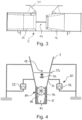
- FIG. 1 An exemplary embodiment of a pneumatic distribution machine is shown schematically, which in the present case is designed in the manner of a seed drill or drill and can be releasably secured, for example, to a usual three-point linkage of a tractor, such as a tractor. It comprises a storage container 1 for holding distribution material, such as seeds and/or fertilizer, with a cover 2, which is supported on supports 3 of a frame. A fan 4 for generating an air flow is also attached to the latter. Below an outlet opening of the storage container 1, which tapers downwards in an approximately funnel shape, there is an in Fig. 2 as well as especially in the Fig. 3 Better recognizable housing 5 of a transfer chamber 14, which is used to transfer the distributed material to a delivery line 6.
- distribution material such as seeds and/or fertilizer
- the distribution unit 7 is formed by a distribution head and comprises a plurality of connections distributed around its circumference, in the present case extending approximately radially outwards, to each of which a distribution line 8 is connected.
- the connection of the distribution lines 8 can be done, for example, by means of a housing 30 (cf. the Fig. 2 ) happen, which is expedient is each equipped with a shut-off device for interrupting the fluidized flow of distributed material as needed in order to be able to provide different working widths or partial width switching.
- these distribution elements are, for example, seed coulters that cannot be seen in detail with feeders 9, so-called harrows, arranged downstream of the same.
- the frame of the distribution machine can also be supported on the floor 11 via support wheels 10 and, in particular, can be lifted by them.
- the Fig. 2 shows the pneumatic conveying components of the distribution machine Fig. 1 , which are used to transfer the material to be distributed from the transfer chamber 14 located inside the housing 5 into the distribution unit 7, which is designed in the manner of a distributor head, by means of the delivery line 6.
- the latter has, at its end facing away from the distribution unit 7, a connecting piece 12 for fluidic contact with the blower 4 (see Fig. 1 ), whereby the outlet of the dosing housing 13 of a dosing element described in more detail below and provided with the reference number 17 opens into the transfer chamber 14, which is traversed by the delivery line 6, downstream of the connecting piece 12.
- the distribution material dispersed in the air flow first reaches a riser pipe section via an approximately horizontal section of the delivery line 6, which flows from below into the center of the distributor head
- Distribution unit 7 opens out, around the circumference of which the radial connections for the housing 30 are arranged, to each of which there is one in the Fig. 2 distribution line 8, which is not shown again in the drawing, is connected.
- the transfer chamber 14 is located in the space between the nozzle 15 and the diffuser 16 of the injector. While the nozzle 15 of the injector is on the in Fig. 2 left end of the housing 5 of the transfer chamber 14 to the blower 4 (see Fig.
- the material to be distributed after it has been metered in a desired mass flow by means of the metering element 17, is transferred into the diffuser 16 in the transfer chamber 14 arranged between the nozzle 15 and the diffuser 16 of the injector by means of the gas stream flowing in via the nozzle 15 and From there it enters the delivery line 6.
- the ones in the Fig. 1 to 3 The distribution machine shown is also equipped with a control and / or regulating device, not shown in the drawing, which controls and / or regulates the functional components of the distribution machine and, among other things, with a further below with reference to Fig. 4 ff weighing device 20 explained in detail, which has a
- a sample of a specific type of material to be distributed can be supplied to calibrate the dosing element 17 in order to record the mass of the sample of material to be distributed gravimetrically.
- the control and/or regulating device is also operatively connected to the metering element 17 in order to control the metering element 17 to the desired target mass flow of material to be distributed depending on the desired target distribution quantity per unit area, the travel speed of the distribution machine and the set working width and/or or to regulate.
- the metering element 17 has one (or more; not shown) which can be set in rotation in a controlled and/or regulated manner by means of a drive (not shown) connected to the control and/or regulating device, which can be set in rotation depending on the type of material to be distributed, for example can be designed in the manner of a cellular wheel, but also in the manner of cam wheels (not shown) or the like. While a (lower) dosing outlet of the dosing housing 13 of the dosing element 17 opens into the transfer chamber 14, upstream of the dosing element 17, a weighing chamber 21 of a weighing device provided overall with the reference number 20 adjoins its (upper) dosing inlet.
- the weighing chamber 21 of the weighing device 20 is arranged downstream of an outlet opening 19 located, for example, at the lower end of the storage container 1, which tapers essentially in a funnel shape downwards, i.e. between the outlet opening 19 of the storage container 1 and the dosing inlet of the dosing housing 13 of the dosing element 17.
- the weighing chamber 21, the dosing element 17 and the transfer chamber 5 form a common structural unit, which is connected on the one hand by the storage container 1 and on the other hand by the delivery line 6 (cf. the Fig.
- the weighing device 20 is designed for the gravimetric determination of the mass of the structural unit formed from the weighing chamber 21, the dosing element 17 and the transfer chamber 5 with the sample of distributed material transferred into the weighing chamber 5 and for this purpose includes, for example, load cells 22 on which the aforementioned structural unit 21 from weighing chamber 21, dosing element 17 and transfer chamber 5 is stored.
- the (upper) inlet of the weighing chamber 21 facing the outlet opening 19 of the storage container 1 can be closed if necessary by means of a slide 23, which is mounted on the storage container 1 and by means of a suitable drive, such as in the form of an electric motor, an electric or hydraulic piston/cylinder unit (each not shown) or the like, can be operated remotely, in particular automatically.
- the weighing chamber 21 is equipped with one or more sensors 24, which are designed to detect the volume of material to be distributed therein and which can be conventional sensors which, for example, determine the filling volume of material to be distributed in the weighing chamber 21 and / or be able to recognize the residual or empty volume remaining above the material to be distributed in the weighing chamber 21.
- a sample of a specific type of material to be distributed can be fed to the weighing chamber 21 from the outlet opening 19 of the storage container 1 for the purpose of calibrating the dosing element 17, with the weighing chamber 21 on the one hand by means of the sensor 24, the volume of the sample of distributed material transferred into the weighing chamber 21 is volumetrically recorded and, on the other hand, its mass can be determined gravimetrically by means of the load cells 22 of the weighing device 20.
- control and/or regulating device is able to determine the specific weight or density of the material to be distributed, on the one hand, from the sensor-determined volume of the sample of material to be distributed in the weighing chamber 21, and, on the other hand, from the gravimetrically determined mass of the sample of material to be distributed transferred into the weighing chamber 21 to determine.
- At least one value representative of the recording volume and the number of metering cells of the metering wheel 18 is stored in the control and/or regulating device, such as both the recording volume of the (individual) metering cells or groups of (multiple) metering cells of the metering wheel 18 as well as the Number or the circumferential dimensions of the dosing cells or groups of dosing cells of the dosing wheel 18, so that the control and / or regulating device adjusts the speed of the dosing wheel 18 of the dosing element 17 to the target mass flow of material to be distributed based on the specific weight determined in this way or can control and/or regulate the mass of distributed material determined by the density of the distributed material per dosing cell or per group of dosing cells of the dosing wheel 18.
- the storage container 1 of the pneumatic distribution machine (see the Fig. 1 to 3 ) has been filled with a specific type of distribution material, e.g. fertilizer and/or seeds.
- the slider 23 is in its closed position and separates the weighing chamber 21 of the weighing device 20 from the outlet opening 19 of the storage container 1.
- a specific type of distribution material e.g. fertilizer and/or seeds.
- the empty volume and/or the filling volume of the “empty” weighing chamber 21 is preferably detected on the one hand by means of the sensor 24; on the other hand, the "empty" weighing chamber 21 is weighed using the load cells 22 of the weighing device 20.
- the slide 23 is then opened in order to transfer a sample of material to be distributed from the outlet opening 19 of the storage container 1 purely as a result of gravity into the weighing chamber 21 of the weighing device 20, after which the inlet of the weighing chamber 21 is closed again by means of the slide 23 (cf. the Fig. 5C ).
- the slide 23 is actuated in particular by means of the control and/or regulating device, which opens the slide 23, for example, until the weighing device 20 has recognized a predeterminable weight of the material to be distributed, whereupon the slide 23 is closed again.
- the volume of this sample of distributed material transferred into the weighing chamber 21 is volumetrically recorded by means of the sensor 24, on the other hand, the mass of this sample of distributed material is determined gravimetrically by means of the weighing cells 22, which can advantageously be done essentially simultaneously for the purpose of a short calibration time.
- the specific weight is then determined by means of the control and / or regulating device or the mass of the type of goods to be distributed is determined.
- the control and/or regulating device in which the value representative of the intake volume and the number of dosing cells of the dosing wheel 18 has been stored (see above), can then adjust the speed of the dosing wheel 18 of the dosing element 17 to the desired target mass flow of material to be distributed to control and/or regulate what happens based on the mass of distributed material per dosing cell or per group of dosing cells of the dosing wheel 18, which is determined by means of the specific weight or the density of the material to be distributed in this way.
- the slide 23 is opened again and the metering wheel 18 of the metering element 17 is set in rotation at the appropriate speed, so that the weighing chamber 21 of the weighing device 20 is free of the distributed material transferred from the outlet opening 19 of the storage container 1 into the metering element 17 gravity flows through (cf. the Fig. 6A ).
- the calibration of the metering element 17 described above can be repeated at regular intervals, such as while the pneumatic distribution machine is moving through the headland of a field.
- the pneumatic distribution machine according to the invention makes it possible to carry out calibration tests in an automated manner, for example at regular intervals, by calibration of a sample of the material to be distributed using the metering wheel 18 of the metering element 17. This can be done in particular in the following with reference to 6A to 6D , in which identical or functionally identical components are provided with the same reference numerals, done in the manner described: In the in the Fig.
- the pneumatic distribution machine is in normal operation; the slide 23 is opened, so that the material to be distributed is transferred from the outlet opening 19 of the storage container 1 through the weighing chamber 21 of the weighing device 20 into the metering housing 13 of the metering element 17, where the metering wheel 18 of the metering element 17 corresponds to the previous calibration according to the desired mass flow of distributed material is set in rotation by means of the control and/or regulating device.
- the slide 23 is now moved into the closed position in order to receive a sample of material to be distributed that has been transferred into the weighing chamber 21 of the weighing device 20 and to prevent further material to be distributed from the outlet opening 19 of the storage container 1 into the weighing chamber 21 to interrupt.
- the mass of the sample of distributed material transferred into the weighing chamber 21 of the weighing device 20 is then determined gravimetrically by means of the weighing cells 22 of the weighing device 20, the metering wheel 18 preferably being temporarily stopped in order to ensure a high level of measurement accuracy.
- the metering wheel 18 of the metering element 17 is then rotated over a predetermined calibration period at the previously determined speed in accordance with the target mass flow of material to be distributed until at least a portion of the sampling volume of material to be distributed recorded in the weighing chamber 21 has been dosed.
- the mass of material to be distributed remaining in the weighing chamber 21 of the weighing device 20 is then determined gravimetrically by means of the weighing cells 22 of the weighing device 20, the metering wheel 18 again preferably being stopped temporarily in order to ensure a high level of measurement accuracy. From the difference between these gravimetrically determined masses of distributed material based on the calibration period, an actual mass flow of distributed material can then be calculated using the control and/or regulating device, which is compared with the target mass flow of distributed material.
- the slide 23 can be opened again and normal operation can be continued, as in the Fig. 6D is shown schematically.
- the speed of the metering wheel 18 of the metering element 17 can be controlled and / or regulated to the target mass flow of distributed material, after which normal operation can be continued (cf . the Fig. 6D ).
Landscapes
- Life Sciences & Earth Sciences (AREA)
- Soil Sciences (AREA)
- Environmental Sciences (AREA)
- Filling Or Emptying Of Bunkers, Hoppers, And Tanks (AREA)
- Sampling And Sample Adjustment (AREA)
- Weight Measurement For Supplying Or Discharging Of Specified Amounts Of Material (AREA)
Claims (15)
- Machine à épandre pneumatique, comprenant :- au moins un réservoir (1) destiné à recevoir un produit à épandre avec au moins une ouverture de sortie (19) ;- au moins un organe de dosage (17) placé en aval de l'ouverture de sortie (19) du réservoir (1) avec au moins une roue de dosage (18) dotée d'une pluralité de cellules de dosage ;- un dispositif de commande et/ou de régulation relié à l'organe de dosage (17), ledit dispositif étant réalisé de façon à commander et/ou réguler la vitesse de rotation de la roue de dosage (18) à un débit massique théorique de produit à épandre en fonction d'au moins un paramètre parmi le groupe comprenant la quantité à épandre théorique par unité de surface, la vitesse de conduite et la largeur de travail ;- au moins une chambre de déversement (5) placée en aval de l'organe de dosage (17) afin de déverser le produit à épandre dosé à l'aide de l'organe de dosage (17) dans au moins une conduite de transport (6) ;- au moins une soufflerie (4) servant à alimenter la conduite de transport (6) avec un courant d'air ;- au moins un organe d'épandage placé en aval de la conduite de transport (6) ; et- au moins un dispositif de pesée (20) avec un caisson de pesée (21) dans lequel peut être amené un échantillon d'un type de produit à épandre défini à extraire en vue d'étalonner l'organe de dosage (17), afin de déterminer la masse de l'échantillon de produit à épandre déversé dans le caisson de pesée de façon gravimétrique ;caractérisée en ce que le caisson de pesée (21), disposé en amont de l'organe de dosage, du dispositif de pesée (20) est équipé d'au moins un capteur (24) permettant de détecter le volume de l'échantillon de produit à épandre amené, que le dispositif de commande et/ou de régulation est conçu pour déterminer le poids spécifique du produit à épandre, d'une part à partir du volume déterminé par voie de capteurs de l'échantillon de produit à épandre dans le caisson de pesée (21), d'autre part à partir de la masse, déterminée de façon gravimétrique à l'aide du dispositif de pesée (20), de l'échantillon de produit à épandre déversé dans le caisson de pesée, et que dans le dispositif de commande et/ou de régulation, au moins une valeur représentative du volume reçu et du nombre de cellules de dosage de la roue de dosage (18) est mémorisée, le dispositif de commande et/ou de régulation étant conçu pour commander et/ou réguler la vitesse de rotation de la roue de dosage (18) de l'organe de dosage (17) en fonction du débit massique théorique de produit à épandre à l'aide de la masse de produit à épandre par cellule de dosage ou par groupe de cellules de dosage de la roue de dosage (18) déterminée à partir du poids spécifique déterminé de produit à épandre déterminé de cette façon.
- Machine à épandre selon la revendication 1, caractérisée en ce que l'organe de dosage (17) comprend une pluralité de roues de dosage (18) différentes pouvant notamment être activées et désactivées individuellement et/ou en groupe ou être interchangées entre elles, une pluralité de valeurs représentatives de volume reçu et de nombre de cellules de dosage des différentes roues de dosage (18) étant mémorisée dans le dispositif de commande et/ou de régulation et le dispositif de commande et/ou de régulation prenant en compte la ou les valeur(s) représentatives du volume reçu et du nombre de cellules de dosage de la roue de dosage (18) ou des roues de dosage (18) se trouvant actuellement en fonctionnement pour la commande et/ou la régulation de la vitesse de rotation de la roue de dosage (18)/des roues de dosage (18) en fonction du débit massique théorique de produit à épandre.
- Machine à épandre selon la revendication 1 ou 2, caractérisée en ce que le caisson de pesée (21), disposé en amont de l'organe de dosage (17), du dispositif de pesée (20) est disposé :- au-dessus d'une admission de dosage de l'organe de dosage (17), pour déverser jusqu'à l'organe de dosage (17) le produit à épandre se trouvant dans le caisson de pesée (21) du fait de la gravitation ; et/ouen aval de l'ouverture de sortie (19) du réservoir (1), le caisson de pesée (21) du dispositif de pesée (20) étant notamment disposé en dessous de l'ouverture de sortie (19) du réservoir (1) pour déverser le produit à épandre amené dans le réservoir (1) par gravitation jusque dans le caisson de pesée (21).
- Machine à épandre selon l'une quelconque des revendications 1 à 3, caractérisée en ce que le caisson de pesée (21) du dispositif de pesée (20) comporte une admission pouvant notamment être refermée à l'aide d'un coulisseau (23).
- Machine à épandre selon l'une quelconque des revendications 1 à 4, caractérisée en ce que le caisson de pesée (21), l'organe de dosage (17) et la chambre de déversement (5) forment une unité de construction commune découplée de façon mécanique d'une part du réservoir (1), d'autre part de la conduite de transport (6), le dispositif de pesée (22) étant réalisé de façon à déterminer de façon gravimétrique la masse de l'unité de construction formée à partir du caisson de pesée (21), de l'organe de dosage (17) et de la chambre de déversement (5) avec l'échantillon de produit à épandre déversé dans le caisson de pesée.
- Procédé pour commander et/ou réguler un organe de dosage (17) d'une machine à épandre pneumatique, comprenant :- au moins un réservoir (1) destiné à recevoir un produit à épandre avec au moins une ouverture de sortie (19) ;- au moins un organe de dosage (17) placé en aval de l'ouverture de sortie (19) du réservoir (1) avec au moins une roue de dosage (18) comprenant une pluralité de cellules de dosage ;- un dispositif de commande et/ou de régulation relié à l'organe de dosage (17) et conçu pour commander et/ou réguler la vitesse de rotation de la roue de dosage (18) à un débit massique théorique de produit à épandre en fonction d'au moins un paramètre parmi le groupe comprenant la quantité à épandre théorique par unité de surface, la vitesse de conduite et la largeur de travail ;- au moins une chambre de déversement (5) placée en aval de l'organe de dosage (17) afin de déverser le produit à épandre dosé à l'aide de l'organe de dosage (17) dans au moins une conduite de transport (6) ;- au moins une soufflerie (4) servant à alimenter la conduite de transport (6) avec un courant d'air ;- au moins un organe d'épandage placé en aval de la conduite de transport (6) ; et- au moins un dispositif de pesée (20) avec un caisson de pesée (21) disposé en amont de l'organe de dosage (17) pouvant amener un échantillon d'un type de produit à épandre défini à extraire en vue d'étalonner l'organe de dosage (17), afin de déterminer de façon gravimétrique la masse de l'échantillon de produit à épandre déversé dans le caisson de pesée ;caractérisé par les étapes suivantes :(a) le déversement d'un échantillon de produit à épandre dans le caisson de pesée (21) du dispositif de pesée (20) ;(b) la détection par voie de capteurs du volume de l'échantillon de produit à épandre déversé dans le caisson de pesée (21) du dispositif de pesée (20) ;(c) la détermination gravimétrique de la masse de l'échantillon de produit à épandre déversé dans le caisson de pesée à l'aide du dispositif de pesée (20) ;(d) la détermination du poids spécifique du produit à épandre d'une part à partir du volume déterminé par voie de capteurs de l'échantillon de produit à épandre dans le caisson de pesée (21), d'autre part à partir de la masse, déterminée de façon gravimétrique à l'aide du dispositif de pesée, de l'échantillon de produit à épandre déversé dans le caisson de pesée ; et(e) la commande et/ou la régulation de la vitesse de rotation de la roue de dosage (18) de l'organe de dosage (17) à l'aide du dispositif de commande et/ou de régulation dans lequel au moins une valeur représentative du volume reçu et du nombre de cellules de dosage de la roue de dosage (18) est mémorisée, en fonction du débit massique théorique de produit à épandre déterminé à l'aide de la masse de produit à épandre par cellule de dosage ou par groupe de cellules de dosage de la roue de dosage (18), à l'aide du poids spécifique déterminé du produit à épandre.
- Procédé selon la revendication 6, caractérisé en ce qu'une pluralité de valeurs sont mémorisées dans le dispositif de commande et/ou de régulation, lesdites valeurs étant représentatives du volume reçu et du nombre de cellules de dosage des différentes roues de dosage (18) de l'organe de dosage (17) comprenant une pluralité de roues de dosage (18) différentes pouvant être activées et désactivées, notamment individuellement et/ou en groupe, ou être remplacées les unes par les autres, dans lequel le dispositif de commande et/ou de régulation prend en compte la/les valeur(s) représentative(s) du volume reçu et du nombre de cellules de dosage de la roue de dosage (18)/des roues de dosage (18) se trouvant actuellement en fonctionnement lors de la commande et/ou de la régulation de la vitesse de rotation de la roue de dosage (18)/des roues de dosage (18) en fonction du débit massique théorique de produit à épandre.
- Procédé selon la revendication 6 ou 7, caractérisé en ce que le produit à épandre est déversé à l'étape (a), notamment du fait de la gravitation, depuis l'ouverture de sortie (19) du réservoir (1) jusque dans le caisson de pesée (21) du dispositif de pesée (20).
- Procédé selon l'une quelconque des revendications 6 à 8, caractérisé en ce que le produit à épandre est déversé du fait de la gravitation du caisson de pesée (21) du dispositif de pesée (20) jusque dans la roue de dosage (18) de l'organe de dosage (17).
- Procédé selon l'une quelconque des revendications 6 à 9, caractérisé en ce que le produit à épandre est déversé à l'étape (a) depuis l'ouverture de sortie (19) du réservoir (1) jusque dans une admission du caisson de pesée (21) du dispositif de pesée (20), après quoi l'admission du caisson de pesée (21) est fermée, notamment à l'aide d'un coulisseau (23), après quoi le volume de l'échantillon de produit à épandre déversé dans le caisson de pesée (21) du dispositif de pesée (20) est détecté par voie de capteurs à l'étape (b) et sa masse est définie de façon gravimétrique à l'étape (c) à l'aide du dispositif de pesée (20).
- Procédé selon l'une quelconque des revendications 6 à 10, caractérisé en ce que lors du fonctionnement de la machine à épandre, le caisson de pesée (21) du dispositif de pesée (20) est traversé par le produit à épandre déversé depuis l'ouverture de sortie (19) du réservoir (1), au niveau de l'organe de dosage (17).
- Procédé selon l'une quelconque des revendications 6 à 11, caractérisé en ce que la détection par voie de capteurs du volume de l'échantillon de produit à épandre déversé jusque dans le caisson de pesée (21) du dispositif de pesée (20) s'effectue à l'étape (b) et que la détermination de façon gravimétrique de la masse de l'échantillon de produit à épandre déversé dans le caisson de pesée s'effectue pour l'essentiel simultanément à l'étape (c) à l'aide du dispositif de pesée. (20).
- Procédé selon l'une quelconque des revendications 6 à 12, caractérisé en ce que :- pour la détection par voie de capteurs du volume de l'échantillon de produit à épandre déversé dans le caisson de pesée (21) du dispositif de pesée (20) à l'étape (b), on détecte d'abord par voie de capteurs le volume vide et/ou le volume de remplissage du caisson de pesée (21), après quoi l'échantillon de produit à épandre est déversé dans le caisson de pesée (21) et le volume vide restant et/ou le volume de remplissage du caisson de pesée (21) rempli avec l'échantillon de produit à épandre est détecté par voie de capteurs, après quoi le volume de l'échantillon de produit à épandre est calculé à partir de la différence avec ce volume vide et/ou ce volume de remplissage du caisson de pesée (21) ; et/ou- pour la détermination gravimétrique de la masse de l'échantillon de produit à épandre déversé dans le caisson de pesée à l'aide du dispositif de pesée (20) à l'étape (c), on pèse d'abord le caisson de pesée (21) à l'aide du dispositif de pesée (20), après quoi l'échantillon de produit à épandre est déversé dans le caisson de pesée (21) et le caisson de pesée (21) rempli de l'échantillon de produit à épandre est pesé à l'aide du dispositif de pesée (20), après quoi la masse de l'échantillon de produit à épandre est calculée à partir de la différence entre ces deux pesées.
- Procédé selon l'une quelconque des revendications 6 à 13, caractérisé en ce que pour réétalonner l'organe de dosage (17), notamment à intervalles de temps périodiques, s'ajoutent les étapes suivantes :(A) déversement d'un échantillon de produit à épandre dans le caisson de pesée (21) du dispositif de pesée (20) ;(B) détermination de façon gravimétrique de la masse de l'échantillon de produit à épandre déversé dans le caisson de pesée (21) du dispositif de pesée (20) à l'aide du dispositif de pesée (20) ;(C) rotation de la roue de dosage (18) de l'organe de dosage (17) pendant une durée d'étalonnage prédéfinie à une vitesse de rotation précédemment déterminée en correspondance avec le débit massique théorique de produit à épandre ;(D) détermination de façon gravimétrique de la masse de produit à épandre restant dans le caisson de pesée (21) du dispositif de pesée (20) à l'aide du dispositif de pesée (20) ;(E) à partir de la différence de ces masses de produit à épandre déterminées de façon gravimétrique par rapport à la durée d'étalonnage, calcul d'un débit massique réel de produit à épandre ;(F) comparaison du débit massique réel ainsi calculé avec le débit massique théorique de produit à épandre ; et(G) en cas d'écart du débit massique réel ainsi calculé de produit à épandre par rapport au débit massique théorique, commande et/ou régulation de la vitesse de rotation de la roue de dosage (18) pour atteindre le débit massique théorique de produit à épandre.
- Procédé selon la revendication 14, caractérisé en ce que les étapes (A) à (G) sont répétées autant de fois que nécessaire pour que le débit massique réel ainsi calculé de produit à épandre corresponde au débit massique théorique ou ne s'écarte pas plus de ce dernier que d'une valeur maximale prédéterminée.
Applications Claiming Priority (1)
| Application Number | Priority Date | Filing Date | Title |
|---|---|---|---|
| DE102020128137.4A DE102020128137A1 (de) | 2020-10-26 | 2020-10-26 | Pneumatische Verteilmaschine und Verfahren zur Steuerung oder Regelung deren Dosierorgans |
Publications (2)
| Publication Number | Publication Date |
|---|---|
| EP3987903A1 EP3987903A1 (fr) | 2022-04-27 |
| EP3987903B1 true EP3987903B1 (fr) | 2023-10-18 |
Family
ID=77640423
Family Applications (1)
| Application Number | Title | Priority Date | Filing Date |
|---|---|---|---|
| EP21194747.8A Active EP3987903B1 (fr) | 2020-10-26 | 2021-09-03 | Machine à épandre pneumatique et procédé de commande ou de régulation de ses organes de dosage |
Country Status (3)
| Country | Link |
|---|---|
| EP (1) | EP3987903B1 (fr) |
| DE (1) | DE102020128137A1 (fr) |
| PL (1) | PL3987903T3 (fr) |
Families Citing this family (3)
| Publication number | Priority date | Publication date | Assignee | Title |
|---|---|---|---|---|
| DE102022105291A1 (de) | 2022-03-07 | 2023-09-07 | Amazonen-Werke H. Dreyer SE & Co. KG | Landwirtschaftliche Verteilmaschine zum Ausbringen von Verteilgut und Verfahren zum Betreiben einer landwirtschaftlichen Verteilmaschine |
| DE102024113619A1 (de) * | 2024-05-15 | 2025-11-20 | Amazonen-Werke H. Dreyer SE & Co. KG | Verfahren zum Betreiben einer landwirtschaftlichen Ausbringmaschine und landwirtschaftliche Ausbringmaschine |
| DE102024121400A1 (de) * | 2024-07-26 | 2026-01-29 | Amazonen-Werke H. Dreyer SE & Co. KG | Zwischenbevorratungseinheit für ein Materialverteilsystem einer Ausbringmaschine, ein Materialverteilsystem für eine Ausbringmaschine und eine Ausbringmaschine |
Family Cites Families (18)
| Publication number | Priority date | Publication date | Assignee | Title |
|---|---|---|---|---|
| DE4324742A1 (de) | 1993-07-23 | 1995-01-26 | Rauch Landmaschfab Gmbh | Sämaschine |
| DE4434963C2 (de) | 1993-10-22 | 1999-11-04 | Rauch Landmaschfab Gmbh | Sämaschine |
| DE4431288A1 (de) | 1994-09-02 | 1996-03-07 | Amazonen Werke Dreyer H | Pneumatische Verteilmaschine |
| DE19747029B4 (de) | 1997-10-24 | 2005-07-14 | Rauch Landmaschinenfabrik Gmbh | Sämaschine |
| DE10037713A1 (de) | 2000-08-02 | 2002-02-21 | Lemken Gmbh & Co Kg | Pneumatische Drillmaschine mit Regeleinrichtung |
| DE10134991B4 (de) | 2001-07-18 | 2013-08-14 | Lemken Gmbh & Co. Kg | Drillmaschine mit automatischer Kalibrierung |
| DE102004030240B4 (de) | 2003-07-15 | 2015-07-09 | Rauch Landmaschinenfabrik Gmbh | Pneumatischer Streuer zum Verteilen von Streugut, insbesondere Dünger, Saatgut oder dergleichen |
| DE102007044178B4 (de) | 2006-10-09 | 2018-12-06 | Rauch Landmaschinenfabrik Gmbh | Pneumatische Sämaschine |
| DE102007036661A1 (de) | 2007-08-03 | 2009-02-05 | Amazonen-Werke H. Dreyer Gmbh & Co. Kg | Pneumatische Verteilmaschine |
| US8408478B2 (en) | 2010-08-20 | 2013-04-02 | Deere & Company | Product distribution apparatus with system and method of automatic meter calibration |
| DE102010053883A1 (de) | 2010-12-09 | 2012-06-14 | Rauch Landmaschinenfabrik Gmbh | Pneumatische Verteilmaschine |
| DE102013005733A1 (de) | 2013-04-05 | 2014-10-09 | Rauch Landmaschinenfabrik Gmbh | Dosiereinheit für eine Verteilmaschine und mit einer solchen Dosiereinheit ausgestattete, insbesondere pneumatische, Verteilmaschine |
| DE102014115020A1 (de) | 2013-10-21 | 2015-04-23 | Müller-Elektronik Gmbh & Co. Kg | Verfahren und Vorrichtung zur Regelung bzw. zum Erfassen von Masseteilchen |
| DE202014009404U1 (de) | 2014-11-27 | 2016-03-02 | Rauch Landmaschinenfabrik Gmbh | Einheit zur Entnahme einer Probe an Verteilgut aus einer Verteilmaschine sowie pneumatische Verteilmaschine und Aufnahmeeinrichtung einer solchen Einheit |
| DE102016012254A1 (de) | 2016-10-14 | 2018-04-19 | Rauch Landmaschinenfabrik Gmbh | Pneumatische Verteilmaschine und Verfahren zur Steuerung oder Regelung deren Dosierorgane mittels Durchführung von Abdrehproben |
| DE102017005094A1 (de) | 2017-05-29 | 2018-11-29 | Rauch Landmaschinenfabrik Gmbh | Landwirtschaftliche Maschine zum Ausbringen von Verteilgut und Dosierorgan für dieselbe |
| DE102018006660A1 (de) | 2018-08-23 | 2020-02-27 | Rauch Landmaschinenfabrik Gmbh | Dosiereinheit für pulver- oder partikelförmiges Verteilgut und Verteilmaschine mit einer solchen Dosiereinheit |
| DE102019000047A1 (de) | 2019-01-08 | 2020-07-09 | Rauch Landmaschinenfabrik Gmbh | Verfahren zur Steuerung und/oder Regelung eines Dosierrades einer Verteilmaschine unter Durchführung von Abdrehproben und hierfür geeignete Verteilmaschine |
-
2020
- 2020-10-26 DE DE102020128137.4A patent/DE102020128137A1/de not_active Withdrawn
-
2021
- 2021-09-03 EP EP21194747.8A patent/EP3987903B1/fr active Active
- 2021-09-03 PL PL21194747.8T patent/PL3987903T3/pl unknown
Also Published As
| Publication number | Publication date |
|---|---|
| DE102020128137A1 (de) | 2022-04-28 |
| PL3987903T3 (pl) | 2024-07-22 |
| EP3987903A1 (fr) | 2022-04-27 |
Similar Documents
| Publication | Publication Date | Title |
|---|---|---|
| EP3525567B1 (fr) | Machine d'épandage pneumatique et procédé de commande ou de réglage de son organe de dosage par l'échantillonnage d'étalonnage | |
| EP3987903B1 (fr) | Machine à épandre pneumatique et procédé de commande ou de régulation de ses organes de dosage | |
| DE102017103640A1 (de) | Verfahren und Steuerungssystem für eine landwirtschaftliche Verteilmaschine zum Dosieren und Ausbringen von granulatartigem Verteilgut | |
| EP3338524B1 (fr) | Semoir monograine agricole et procédé | |
| EP3777500B1 (fr) | Procédé d'épandage de matière granulaire | |
| EP3908097B1 (fr) | Procédé de commande et/ou de régulation d'une roue de dosage d'une machine d'épandage en effectuant des tests d'étalonnage, et machine d'épandage convenant à cette fin | |
| EP3629694A1 (fr) | Machine agricole pour l'épandage d'un produit à répartir et organe de dosage pour celle-ci | |
| DE102020204701A1 (de) | System zur Verteilung von Saatgut und landwirtschaftlichen Partikeln | |
| EP3409090A1 (fr) | Machine d'épandage pneumatique et procédé de distribution de produit à épandre au moyen de ladite machine d'épandage pneumatique | |
| EP2932818A1 (fr) | Dispositif d'épandage et procédé d'extraction du produit à épandre sous forme de granulés | |
| DE3889531T2 (de) | Landwirtschaftliche Maschine, um ein Produkt zu streuen. | |
| EP4349148A1 (fr) | Machine de distribution pneumatique et procédé de régulation du débit massique de son organe de dosage | |
| EP0216057A1 (fr) | Semoir pneumatique monograine | |
| WO2010083823A1 (fr) | Dispositif et procédé de détermination, en fonction de la masse, du rendement de grains de céréales sur des moissonneuses | |
| WO2021083536A1 (fr) | Machine d'épandage pneumatique | |
| EP3704923B1 (fr) | Dispositif pour un semoir agricole, procédé de séparation des semences dans un dispositif pour un semoir agricole ainsi que semoir | |
| DE202004004381U1 (de) | Pneumatisch arbeitende Verteilmaschine | |
| WO2020035340A1 (fr) | Machine de distribution de produits granulaires | |
| DE102022123246A1 (de) | Vorratsbehälter einer landwirtschaftlichen Verteilmaschine und Verfahren zum Umrüsten eines Vorratsbehälters | |
| DE102020133357A1 (de) | Dosiersystem einer landwirtschaftlichen Sämaschine | |
| DE8817220U1 (de) | Landwirtschaftliche Maschine zum Verteilen von Gut | |
| EP1836887B1 (fr) | Machine à semer | |
| DE102024131638A1 (de) | Landwirtschaftliche Verteilmaschine, Reiheneinheit und Verfahren zur kombinierten Einzelkornsaat und Drillsaat | |
| DE3821738A1 (de) | Pneumatikduengerstreuer | |
| DE102023115653A1 (de) | Behälter für ein landwirtschaftliches gut mit einer fördereinrichtung, landwirtschaftliches arbeitsgerät mit einem behälter und verfahren zum betrieb eines landwirtschaftlichen arbeitsgeräts |
Legal Events
| Date | Code | Title | Description |
|---|---|---|---|
| PUAI | Public reference made under article 153(3) epc to a published international application that has entered the european phase |
Free format text: ORIGINAL CODE: 0009012 |
|
| STAA | Information on the status of an ep patent application or granted ep patent |
Free format text: STATUS: THE APPLICATION HAS BEEN PUBLISHED |
|
| AK | Designated contracting states |
Kind code of ref document: A1 Designated state(s): AL AT BE BG CH CY CZ DE DK EE ES FI FR GB GR HR HU IE IS IT LI LT LU LV MC MK MT NL NO PL PT RO RS SE SI SK SM TR |
|
| STAA | Information on the status of an ep patent application or granted ep patent |
Free format text: STATUS: REQUEST FOR EXAMINATION WAS MADE |
|
| 17P | Request for examination filed |
Effective date: 20220428 |
|
| RBV | Designated contracting states (corrected) |
Designated state(s): AL AT BE BG CH CY CZ DE DK EE ES FI FR GB GR HR HU IE IS IT LI LT LU LV MC MK MT NL NO PL PT RO RS SE SI SK SM TR |
|
| GRAP | Despatch of communication of intention to grant a patent |
Free format text: ORIGINAL CODE: EPIDOSNIGR1 |
|
| STAA | Information on the status of an ep patent application or granted ep patent |
Free format text: STATUS: GRANT OF PATENT IS INTENDED |
|
| RIC1 | Information provided on ipc code assigned before grant |
Ipc: A01C 17/00 20060101ALN20230621BHEP Ipc: A01C 7/12 20060101ALI20230621BHEP Ipc: A01C 7/10 20060101ALI20230621BHEP Ipc: A01C 7/08 20060101AFI20230621BHEP |
|
| INTG | Intention to grant announced |
Effective date: 20230705 |
|
| GRAS | Grant fee paid |
Free format text: ORIGINAL CODE: EPIDOSNIGR3 |
|
| GRAA | (expected) grant |
Free format text: ORIGINAL CODE: 0009210 |
|
| STAA | Information on the status of an ep patent application or granted ep patent |
Free format text: STATUS: THE PATENT HAS BEEN GRANTED |
|
| AK | Designated contracting states |
Kind code of ref document: B1 Designated state(s): AL AT BE BG CH CY CZ DE DK EE ES FI FR GB GR HR HU IE IS IT LI LT LU LV MC MK MT NL NO PL PT RO RS SE SI SK SM TR |
|
| REG | Reference to a national code |
Ref country code: GB Ref legal event code: FG4D Free format text: NOT ENGLISH |
|
| REG | Reference to a national code |
Ref country code: CH Ref legal event code: EP |
|
| P01 | Opt-out of the competence of the unified patent court (upc) registered |
Effective date: 20230927 |
|
| REG | Reference to a national code |
Ref country code: IE Ref legal event code: FG4D Free format text: LANGUAGE OF EP DOCUMENT: GERMAN |
|
| REG | Reference to a national code |
Ref country code: DE Ref legal event code: R096 Ref document number: 502021001735 Country of ref document: DE |
|
| REG | Reference to a national code |
Ref country code: DE Ref legal event code: R081 Ref document number: 502021001735 Country of ref document: DE Owner name: RAUCH LANDMASCHINENFABRIK GESELLSCHAFT MIT BES, DE Free format text: FORMER OWNER: RAUCH LANDMASCHINENFABRIK GESELLSCHAFT MIT BESCHRAENKTER HAFTUNG, 76547 SINZHEIM, DE |
|
| REG | Reference to a national code |
Ref country code: SE Ref legal event code: TRGR |
|
| REG | Reference to a national code |
Ref country code: LT Ref legal event code: MG9D |
|
| REG | Reference to a national code |
Ref country code: NL Ref legal event code: MP Effective date: 20231018 |
|
| PG25 | Lapsed in a contracting state [announced via postgrant information from national office to epo] |
Ref country code: NL Free format text: LAPSE BECAUSE OF FAILURE TO SUBMIT A TRANSLATION OF THE DESCRIPTION OR TO PAY THE FEE WITHIN THE PRESCRIBED TIME-LIMIT Effective date: 20231018 |
|
| PG25 | Lapsed in a contracting state [announced via postgrant information from national office to epo] |
Ref country code: GR Free format text: LAPSE BECAUSE OF FAILURE TO SUBMIT A TRANSLATION OF THE DESCRIPTION OR TO PAY THE FEE WITHIN THE PRESCRIBED TIME-LIMIT Effective date: 20240119 |
|
| PG25 | Lapsed in a contracting state [announced via postgrant information from national office to epo] |
Ref country code: IS Free format text: LAPSE BECAUSE OF FAILURE TO SUBMIT A TRANSLATION OF THE DESCRIPTION OR TO PAY THE FEE WITHIN THE PRESCRIBED TIME-LIMIT Effective date: 20240218 |
|
| PG25 | Lapsed in a contracting state [announced via postgrant information from national office to epo] |
Ref country code: LT Free format text: LAPSE BECAUSE OF FAILURE TO SUBMIT A TRANSLATION OF THE DESCRIPTION OR TO PAY THE FEE WITHIN THE PRESCRIBED TIME-LIMIT Effective date: 20231018 |
|
| PG25 | Lapsed in a contracting state [announced via postgrant information from national office to epo] |
Ref country code: ES Free format text: LAPSE BECAUSE OF FAILURE TO SUBMIT A TRANSLATION OF THE DESCRIPTION OR TO PAY THE FEE WITHIN THE PRESCRIBED TIME-LIMIT Effective date: 20231018 |
|
| PG25 | Lapsed in a contracting state [announced via postgrant information from national office to epo] |
Ref country code: LT Free format text: LAPSE BECAUSE OF FAILURE TO SUBMIT A TRANSLATION OF THE DESCRIPTION OR TO PAY THE FEE WITHIN THE PRESCRIBED TIME-LIMIT Effective date: 20231018 Ref country code: IS Free format text: LAPSE BECAUSE OF FAILURE TO SUBMIT A TRANSLATION OF THE DESCRIPTION OR TO PAY THE FEE WITHIN THE PRESCRIBED TIME-LIMIT Effective date: 20240218 Ref country code: GR Free format text: LAPSE BECAUSE OF FAILURE TO SUBMIT A TRANSLATION OF THE DESCRIPTION OR TO PAY THE FEE WITHIN THE PRESCRIBED TIME-LIMIT Effective date: 20240119 Ref country code: ES Free format text: LAPSE BECAUSE OF FAILURE TO SUBMIT A TRANSLATION OF THE DESCRIPTION OR TO PAY THE FEE WITHIN THE PRESCRIBED TIME-LIMIT Effective date: 20231018 Ref country code: BG Free format text: LAPSE BECAUSE OF FAILURE TO SUBMIT A TRANSLATION OF THE DESCRIPTION OR TO PAY THE FEE WITHIN THE PRESCRIBED TIME-LIMIT Effective date: 20240118 Ref country code: PT Free format text: LAPSE BECAUSE OF FAILURE TO SUBMIT A TRANSLATION OF THE DESCRIPTION OR TO PAY THE FEE WITHIN THE PRESCRIBED TIME-LIMIT Effective date: 20240219 |
|
| PG25 | Lapsed in a contracting state [announced via postgrant information from national office to epo] |
Ref country code: RS Free format text: LAPSE BECAUSE OF FAILURE TO SUBMIT A TRANSLATION OF THE DESCRIPTION OR TO PAY THE FEE WITHIN THE PRESCRIBED TIME-LIMIT Effective date: 20231018 Ref country code: NO Free format text: LAPSE BECAUSE OF FAILURE TO SUBMIT A TRANSLATION OF THE DESCRIPTION OR TO PAY THE FEE WITHIN THE PRESCRIBED TIME-LIMIT Effective date: 20240118 Ref country code: LV Free format text: LAPSE BECAUSE OF FAILURE TO SUBMIT A TRANSLATION OF THE DESCRIPTION OR TO PAY THE FEE WITHIN THE PRESCRIBED TIME-LIMIT Effective date: 20231018 Ref country code: HR Free format text: LAPSE BECAUSE OF FAILURE TO SUBMIT A TRANSLATION OF THE DESCRIPTION OR TO PAY THE FEE WITHIN THE PRESCRIBED TIME-LIMIT Effective date: 20231018 |
|
| PG25 | Lapsed in a contracting state [announced via postgrant information from national office to epo] |
Ref country code: DK Free format text: LAPSE BECAUSE OF FAILURE TO SUBMIT A TRANSLATION OF THE DESCRIPTION OR TO PAY THE FEE WITHIN THE PRESCRIBED TIME-LIMIT Effective date: 20231018 |
|
| REG | Reference to a national code |
Ref country code: DE Ref legal event code: R097 Ref document number: 502021001735 Country of ref document: DE |
|
| PG25 | Lapsed in a contracting state [announced via postgrant information from national office to epo] |
Ref country code: CZ Free format text: LAPSE BECAUSE OF FAILURE TO SUBMIT A TRANSLATION OF THE DESCRIPTION OR TO PAY THE FEE WITHIN THE PRESCRIBED TIME-LIMIT Effective date: 20231018 |
|
| PG25 | Lapsed in a contracting state [announced via postgrant information from national office to epo] |
Ref country code: SK Free format text: LAPSE BECAUSE OF FAILURE TO SUBMIT A TRANSLATION OF THE DESCRIPTION OR TO PAY THE FEE WITHIN THE PRESCRIBED TIME-LIMIT Effective date: 20231018 |
|
| PG25 | Lapsed in a contracting state [announced via postgrant information from national office to epo] |
Ref country code: SM Free format text: LAPSE BECAUSE OF FAILURE TO SUBMIT A TRANSLATION OF THE DESCRIPTION OR TO PAY THE FEE WITHIN THE PRESCRIBED TIME-LIMIT Effective date: 20231018 Ref country code: SK Free format text: LAPSE BECAUSE OF FAILURE TO SUBMIT A TRANSLATION OF THE DESCRIPTION OR TO PAY THE FEE WITHIN THE PRESCRIBED TIME-LIMIT Effective date: 20231018 Ref country code: RO Free format text: LAPSE BECAUSE OF FAILURE TO SUBMIT A TRANSLATION OF THE DESCRIPTION OR TO PAY THE FEE WITHIN THE PRESCRIBED TIME-LIMIT Effective date: 20231018 Ref country code: IT Free format text: LAPSE BECAUSE OF FAILURE TO SUBMIT A TRANSLATION OF THE DESCRIPTION OR TO PAY THE FEE WITHIN THE PRESCRIBED TIME-LIMIT Effective date: 20231018 Ref country code: EE Free format text: LAPSE BECAUSE OF FAILURE TO SUBMIT A TRANSLATION OF THE DESCRIPTION OR TO PAY THE FEE WITHIN THE PRESCRIBED TIME-LIMIT Effective date: 20231018 Ref country code: DK Free format text: LAPSE BECAUSE OF FAILURE TO SUBMIT A TRANSLATION OF THE DESCRIPTION OR TO PAY THE FEE WITHIN THE PRESCRIBED TIME-LIMIT Effective date: 20231018 Ref country code: CZ Free format text: LAPSE BECAUSE OF FAILURE TO SUBMIT A TRANSLATION OF THE DESCRIPTION OR TO PAY THE FEE WITHIN THE PRESCRIBED TIME-LIMIT Effective date: 20231018 |
|
| PLBE | No opposition filed within time limit |
Free format text: ORIGINAL CODE: 0009261 |
|
| STAA | Information on the status of an ep patent application or granted ep patent |
Free format text: STATUS: NO OPPOSITION FILED WITHIN TIME LIMIT |
|
| 26N | No opposition filed |
Effective date: 20240719 |
|
| PG25 | Lapsed in a contracting state [announced via postgrant information from national office to epo] |
Ref country code: SI Free format text: LAPSE BECAUSE OF FAILURE TO SUBMIT A TRANSLATION OF THE DESCRIPTION OR TO PAY THE FEE WITHIN THE PRESCRIBED TIME-LIMIT Effective date: 20231018 |
|
| PG25 | Lapsed in a contracting state [announced via postgrant information from national office to epo] |
Ref country code: SI Free format text: LAPSE BECAUSE OF FAILURE TO SUBMIT A TRANSLATION OF THE DESCRIPTION OR TO PAY THE FEE WITHIN THE PRESCRIBED TIME-LIMIT Effective date: 20231018 |
|
| PG25 | Lapsed in a contracting state [announced via postgrant information from national office to epo] |
Ref country code: MC Free format text: LAPSE BECAUSE OF FAILURE TO SUBMIT A TRANSLATION OF THE DESCRIPTION OR TO PAY THE FEE WITHIN THE PRESCRIBED TIME-LIMIT Effective date: 20231018 |
|
| REG | Reference to a national code |
Ref country code: CH Ref legal event code: PL |
|
| PG25 | Lapsed in a contracting state [announced via postgrant information from national office to epo] |
Ref country code: LU Free format text: LAPSE BECAUSE OF NON-PAYMENT OF DUE FEES Effective date: 20240903 |
|
| REG | Reference to a national code |
Ref country code: BE Ref legal event code: MM Effective date: 20240930 |
|
| PG25 | Lapsed in a contracting state [announced via postgrant information from national office to epo] |
Ref country code: BE Free format text: LAPSE BECAUSE OF NON-PAYMENT OF DUE FEES Effective date: 20240930 |
|
| PG25 | Lapsed in a contracting state [announced via postgrant information from national office to epo] |
Ref country code: CH Free format text: LAPSE BECAUSE OF NON-PAYMENT OF DUE FEES Effective date: 20240930 |
|
| PG25 | Lapsed in a contracting state [announced via postgrant information from national office to epo] |
Ref country code: IE Free format text: LAPSE BECAUSE OF NON-PAYMENT OF DUE FEES Effective date: 20240903 |
|
| PG25 | Lapsed in a contracting state [announced via postgrant information from national office to epo] |
Ref country code: FI Free format text: LAPSE BECAUSE OF FAILURE TO SUBMIT A TRANSLATION OF THE DESCRIPTION OR TO PAY THE FEE WITHIN THE PRESCRIBED TIME-LIMIT Effective date: 20231019 |
|
| PGFP | Annual fee paid to national office [announced via postgrant information from national office to epo] |
Ref country code: DE Payment date: 20250903 Year of fee payment: 5 |
|
| PGFP | Annual fee paid to national office [announced via postgrant information from national office to epo] |
Ref country code: PL Payment date: 20250903 Year of fee payment: 5 |
|
| PGFP | Annual fee paid to national office [announced via postgrant information from national office to epo] |
Ref country code: AT Payment date: 20251020 Year of fee payment: 5 Ref country code: FR Payment date: 20250925 Year of fee payment: 5 |
|
| PGFP | Annual fee paid to national office [announced via postgrant information from national office to epo] |
Ref country code: SE Payment date: 20250922 Year of fee payment: 5 |
|
| PG25 | Lapsed in a contracting state [announced via postgrant information from national office to epo] |
Ref country code: CY Free format text: LAPSE BECAUSE OF FAILURE TO SUBMIT A TRANSLATION OF THE DESCRIPTION OR TO PAY THE FEE WITHIN THE PRESCRIBED TIME-LIMIT; INVALID AB INITIO Effective date: 20210903 |
|
| PG25 | Lapsed in a contracting state [announced via postgrant information from national office to epo] |
Ref country code: HU Free format text: LAPSE BECAUSE OF FAILURE TO SUBMIT A TRANSLATION OF THE DESCRIPTION OR TO PAY THE FEE WITHIN THE PRESCRIBED TIME-LIMIT; INVALID AB INITIO Effective date: 20210903 |