EP3988028A1 - Pulswellengeschwindigkeitsmessverfahren und ultraschallvorrichtung - Google Patents
Pulswellengeschwindigkeitsmessverfahren und ultraschallvorrichtung Download PDFInfo
- Publication number
- EP3988028A1 EP3988028A1 EP21200591.2A EP21200591A EP3988028A1 EP 3988028 A1 EP3988028 A1 EP 3988028A1 EP 21200591 A EP21200591 A EP 21200591A EP 3988028 A1 EP3988028 A1 EP 3988028A1
- Authority
- EP
- European Patent Office
- Prior art keywords
- sampling
- pulse wave
- target
- blood vessel
- ultrasound image
- Prior art date
- Legal status (The legal status is an assumption and is not a legal conclusion. Google has not performed a legal analysis and makes no representation as to the accuracy of the status listed.)
- Withdrawn
Links
- 238000002604 ultrasonography Methods 0.000 title claims abstract description 176
- 238000000034 method Methods 0.000 title claims abstract description 61
- 238000005070 sampling Methods 0.000 claims abstract description 333
- 210000004204 blood vessel Anatomy 0.000 claims abstract description 124
- 230000000747 cardiac effect Effects 0.000 claims abstract description 57
- 238000006073 displacement reaction Methods 0.000 claims abstract description 40
- 238000012545 processing Methods 0.000 claims abstract description 16
- 238000004364 calculation method Methods 0.000 claims abstract description 7
- 238000005259 measurement Methods 0.000 claims description 41
- 230000015654 memory Effects 0.000 claims description 25
- 238000012216 screening Methods 0.000 claims description 9
- 238000005260 corrosion Methods 0.000 claims description 6
- 230000007797 corrosion Effects 0.000 claims description 6
- 230000004044 response Effects 0.000 claims description 6
- 230000036772 blood pressure Effects 0.000 description 11
- 238000004891 communication Methods 0.000 description 9
- 239000000523 sample Substances 0.000 description 9
- 210000001715 carotid artery Anatomy 0.000 description 5
- 230000015572 biosynthetic process Effects 0.000 description 4
- 210000002321 radial artery Anatomy 0.000 description 4
- 238000012360 testing method Methods 0.000 description 4
- 238000010586 diagram Methods 0.000 description 3
- 230000006870 function Effects 0.000 description 3
- 210000001367 artery Anatomy 0.000 description 2
- 239000008280 blood Substances 0.000 description 2
- 210000004369 blood Anatomy 0.000 description 2
- 230000008859 change Effects 0.000 description 2
- 238000000605 extraction Methods 0.000 description 2
- 238000010191 image analysis Methods 0.000 description 2
- 238000012986 modification Methods 0.000 description 2
- 230000004048 modification Effects 0.000 description 2
- 230000008569 process Effects 0.000 description 2
- 241001270131 Agaricus moelleri Species 0.000 description 1
- 206010003210 Arteriosclerosis Diseases 0.000 description 1
- 208000011775 arteriosclerosis disease Diseases 0.000 description 1
- 238000001514 detection method Methods 0.000 description 1
- 230000003205 diastolic effect Effects 0.000 description 1
- 239000000284 extract Substances 0.000 description 1
- 210000001105 femoral artery Anatomy 0.000 description 1
- 210000002683 foot Anatomy 0.000 description 1
- 230000002452 interceptive effect Effects 0.000 description 1
- 238000013178 mathematical model Methods 0.000 description 1
- 230000003287 optical effect Effects 0.000 description 1
- 230000002093 peripheral effect Effects 0.000 description 1
- 230000001902 propagating effect Effects 0.000 description 1
- 230000000541 pulsatile effect Effects 0.000 description 1
- 230000010349 pulsation Effects 0.000 description 1
- 238000010183 spectrum analysis Methods 0.000 description 1
Images


Classifications
-
- A—HUMAN NECESSITIES
- A61—MEDICAL OR VETERINARY SCIENCE; HYGIENE
- A61B—DIAGNOSIS; SURGERY; IDENTIFICATION
- A61B8/00—Diagnosis using ultrasonic, sonic or infrasonic waves
- A61B8/08—Clinical applications
- A61B8/0891—Clinical applications for diagnosis of blood vessels
-
- A—HUMAN NECESSITIES
- A61—MEDICAL OR VETERINARY SCIENCE; HYGIENE
- A61B—DIAGNOSIS; SURGERY; IDENTIFICATION
- A61B8/00—Diagnosis using ultrasonic, sonic or infrasonic waves
- A61B8/52—Devices using data or image processing specially adapted for diagnosis using ultrasonic, sonic or infrasonic waves
- A61B8/5215—Devices using data or image processing specially adapted for diagnosis using ultrasonic, sonic or infrasonic waves involving processing of medical diagnostic data
- A61B8/5223—Devices using data or image processing specially adapted for diagnosis using ultrasonic, sonic or infrasonic waves involving processing of medical diagnostic data for extracting a diagnostic or physiological parameter from medical diagnostic data
-
- A—HUMAN NECESSITIES
- A61—MEDICAL OR VETERINARY SCIENCE; HYGIENE
- A61B—DIAGNOSIS; SURGERY; IDENTIFICATION
- A61B8/00—Diagnosis using ultrasonic, sonic or infrasonic waves
- A61B8/06—Measuring blood flow
-
- A—HUMAN NECESSITIES
- A61—MEDICAL OR VETERINARY SCIENCE; HYGIENE
- A61B—DIAGNOSIS; SURGERY; IDENTIFICATION
- A61B8/00—Diagnosis using ultrasonic, sonic or infrasonic waves
- A61B8/08—Clinical applications
- A61B8/0883—Clinical applications for diagnosis of the heart
Definitions
- the present disclosure relates to the technical field of image processing, in particular to a pulse wave velocity measuring method and an ultrasound device.
- Pulse wave velocity refers to the conduction velocity of a pressure wave propagating along the wall of a main artery resulting from each pulsatile blood ejection of the heart.
- the principle that the conduction velocity of fluctuation (namely, pulse waves) generated by blood output by the heart passing through blood vessels during arteriosclerosis is increased can be applied to measure the conduction velocity of fluctuation between two heartbeats so as to judge the elasticity degree of the blood vessels; and also, PWV may be used to estimate blood pressure and the like. Therefore, the method has great clinical significance on accurate measurement of PWV
- Measurement of PWV in the prior art is generally carried out by a dedicated PWV measurement machine, the existing measurement machine is provided with four probes, one probe acts on the carotid artery and the other three probes may test PWV at three points, such as the carotid artery to the radial artery, femoral artery and dorsalis pedis artery.
- the working principle is that pulsation is judged according to the change track of echo of the wall of a blood vessel.
- the length of a blood vessel between the carotid artery and the radial artery may be estimated by using two probes corresponding to the carotid artery and the radial artery; meanwhile, signals measured by the two probes corresponding to the carotid artery and the radial artery may be analyzed to determine a time difference between the two measurement points; and finally, the PWV is calculated by using the estimated length of the blood vessel and the time difference.
- the length of the blood vessel is estimated by using the positions of the probes, and the time difference is acquired by analyzing the signals measured by the two probes, so that the estimated length of the blood vessel has a certain estimation error, and the time difference determined by using the signals measured by the two probes also has a certain error, so that the accuracy of the measured PWV is low.
- embodiments of the present disclosure provide a pulse wave velocity measuring method and an ultrasound device so as to solve the problem of low PWV measurement accuracy.
- an embodiment of the present disclosure provides a pulse wave velocity measuring method, comprising:
- the pulse wave velocity measuring method provided by the embodiment of the present disclosure, through the at least two sampling areas in the target blood vessel ultrasound image, the distance between the sampling areas and the time difference between the preset points are determined based on the sampling areas in the target blood vessel ultrasound image, that is, the pulse wave velocity of the target body is quantitatively calculated from the target blood vessel ultrasound image, and therefore, the accuracy of determining the pulse wave velocity of the target body is improved.
- determining the pulse wave velocity of the target body comprises:
- the pulse wave velocity measuring method under the condition that two sampling areas are arranged, the target pulse wave velocities are acquired through multiple times of measurement, and then the pulse wave velocity of the target body is determined on this basis, so that errors caused by single measurement may be avoided, and the accuracy of increasing the pulse wave velocity of the target body is further improved.
- determining the pulse wave velocity of the target body comprises:
- any two sampling areas are utilized to form at least two sets of sampling area combinations, so that under the condition of single measurement, different sampling area combinations may be utilized to acquire corresponding target pulse wave velocities, and based on the target pulse wave velocities corresponding to the sampling area combinations, the pulse wave velocity of the target body is determined.
- the accuracy of determining the pulse wave velocity of the target body is improved
- at least two target pulse wave velocities may be acquired through one-time measurement, and the efficiency of determining the pulse wave velocity of the target body is improved.
- determining the pulse wave velocity of the target body comprises:
- the target pulse wave velocities are screened by calculating the confidence level of the target pulse wave velocity, so that the reliability of the target pulse wave velocities acquired after screening can be ensured, and further the accuracy of calculation of the pulse wave velocity of the target body is ensured.
- acquiring the target blood vessel ultrasound image of the target body comprises:
- the pulse wave velocity measuring method provided by the embodiment of the present disclosure, corresponding to different working modes, different sampling areas are formed on the blood vessel ultrasound image, so that the reliability of arrangement of the sampling areas can be ensured.
- forming at least two sampling gates or sampling lines on the blood vessel ultrasound image to acquire the target blood vessel ultrasound image comprises: in response to the operation of arranging the at least two sampling gates or sampling lines on the blood vessel ultrasound image, forming at least two sampling gates or sampling lines on the blood vessel ultrasound image to acquire the target blood vessel ultrasound image.
- the sampling areas are manually arranged on the blood vessel ultrasound image, so that the arranged sampling area can meet the requirements of a user.
- forming at least two sampling gates or sampling lines on the blood vessel ultrasound image to acquire the target blood vessel ultrasound image comprises:
- the sampling areas are automatically formed on the blood vessel ultrasound image, so that the efficiency of arranging the sampling areas is improved, and further, the efficiency of determining the pulse wave velocity of the target body is improved.
- analyzing the images in the at least two sampling areas to acquire the time difference of displacement of the preset points in the cardiac cycle between the at least two sampling areas comprises:
- the images in the sampling areas are subjected to binarization processing before the envelope lines are extracted, so that on the one hand, the image analysis efficiency is ensured, on the other hand, the data processing amount during subsequent envelope line extraction is reduced, and the efficiency of determining the pulse wave velocity of the target body is further improved.
- carrying out binarization processing on the images in the at least two sampling areas to acquire the first images corresponding to the sampling areas comprises:
- the gray scale threshold is determined by utilizing the entropy value corresponding to each gray scale in the gray scale map, then the determined gray scale threshold is utilized to screen the pixel points in the gray scale map to form the first images, wherein because the gray scale threshold is determined by utilizing the entropy value corresponding to each gray scale, and is not set artificially, the reliability of pixel point screening can be ensured, and thus the accuracy of the formed first images is improved.
- forming the first images by utilizing the effective pixel points comprises:
- corrosion and expansion are carried out on the basis of the effective pixel points, isolated points and burrs in the second images may be removed, and thus the reliability of the first images is further improved.
- the method further comprises: determining the blood pressure of the target body by utilizing the pulse wave velocity of the target body.
- the blood pressure of the target body is determined on the basis of the pulse wave velocity of the target body, and the accuracy of determining the blood pressure of the target body may be ensured.
- an embodiment of the present disclosure also provides a pulse wave velocity measuring device, comprising:
- the pulse wave velocity measuring device provided by the embodiment of the present disclosure, at least two sampling areas are formed in the target blood vessel ultrasound image, and the distance between the sampling areas and the time difference between the preset points are determined based on the sampling areas in the target blood vessel ultrasound image subsequently, namely, the pulse wave velocity of the target body is quantitatively calculated from the target blood vessel ultrasound image, so that the accuracy of determining the pulse wave velocity of the target body is improved.
- an embodiment of the present disclosure provides an ultrasound device, comprising: a memory and a processor, wherein the memory and the processor are in communication connection with each other, computer instructions are stored in the memory, the processor executes the computer instructions so as to execute the pulse wave velocity measuring method of the first aspect or any one of the implementation modes of the first aspect.
- an embodiment of the present disclosure provides a computer-readable storage medium storing computer instructions for enabling a computer to execute the pulse wave velocity measuring method of the first aspect or any one of implementation modes of the first aspect.
- a pulse wave velocity measuring method provided by an embodiment of the present disclosure may be applied to any electronic equipment with an image processing function, such as a computer, a mobile phone and an ultrasound device.
- an image processing function such as a computer, a mobile phone and an ultrasound device.
- the ultrasound device is described in detail as an example.
- an embodiment of a pulse wave velocity measuring method is provided, it needs to be noted that steps shown in the flow chart of the figure may be executed in a computer system such as a set of computer executable instructions, and that, although a logical sequence is shown in the flow chart, in some cases, the steps shown or described may be executed in a sequence different from the sequence herein.
- a pulse wave velocity measuring method is provided, and can be used for an ultrasound device
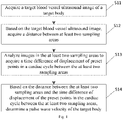
- Fig. 1 is a flow chart of a pulse wave velocity measuring method according to an embodiment of the present disclosure, as shown in Fig. 1 , the flow comprises the following steps.
- a target blood vessel ultrasound image of a target body is acquired.
- the target blood vessel ultrasound image comprises at least two sampling areas.
- the target blood vessel ultrasound image may be a real-time blood vessel ultrasound image of the target body, and may also be a historical blood vessel ultrasound image of the target body or the like, and the source of the target blood vessel ultrasound image is not limited in any way herein.
- At least two sampling areas in the target blood vessel ultrasound image may be formed in the blood vessel ultrasound image after the blood vessel ultrasound image is acquired; or after the ultrasound device is started, at least two sampling areas are formed on a display interface of the ultrasound device, and then the blood vessel ultrasound image of the target body is collected, so that at least two sampling areas are formed in the blood vessel ultrasound image, and thus the target blood vessel ultrasound image is acquired.
- sampling areas may be automatically formed or may also be formed in an interactive manner.
- the specific mode of forming the sampling areas is not limited, and corresponding setting may be carried out according to actual conditions.
- a number of the sampling areas formed in the target blood vessel ultrasound image may be two, three or four and the like, the specific set number may be correspondingly set according to requirements, and it only needs to guarantee that the number of the sampling areas formed in the target blood vessel ultrasound image is at least two.
- the sampling areas may also be regarded as sampling areas in the target blood vessel ultrasound image, and may be sampling gates, sampling lines and the like.
- sampling areas There are three sampling areas, namely a sampling area A, a sampling area B and a sampling area C, in the target blood vessel ultrasound image, and after the sampling area A, the sampling area B and the sampling area C are determined, a distance between the sampling area A and the sampling area B, a distance between the sampling area A and the sampling area C and a distance between the sampling area B and the sampling area C may be acquired.
- a distance between the sampling area A and the sampling area B a distance between the sampling area A and the sampling area C and a distance between the sampling area B and the sampling area C may be acquired.
- images in the at least two sampling areas are analyzed to acquire a time difference of displacement of preset points in a cardiac cycle between the at least two sampling areas.
- the ultrasound device After the ultrasound device forms the sampling areas, images in the sampling areas are analyzed and processed, and positions corresponding to the preset points in a cardiac cycle are determined in each sampling area.
- the preset point may be a starting point, an end point, or other characteristic point of the cardiac cycle, and the like, which is not limited in any way herein.
- the cardiac cycle of the target body may be determined in the target blood vessel ultrasound image, wherein a manner of determining the cardiac cycle is not limited herein, for example, a cardiac cycle detection model may be utilized, also, features corresponding to systolic and/or diastolic phases in the target blood vessel ultrasound image may be utilized, or the like.
- the ultrasound device may determine positions corresponding to the preset points in the cardiac cycle in the sampling areas, for example, a position of a starting point of the cardiac cycle, a position of an end point of the cardiac cycle, or the like may be determined in each sampling area.
- the ultrasound device determines the position of the starting point of the cardiac cycle in each sampling area
- the time difference of displacement of the starting points of the cardiac cycle between any two sampling areas may be determined by carrying out spectrum analysis on images in the sampling areas, and the determined time difference is the motion time of the pulse wave between the two sampling areas.
- the ultrasound device determines the starting point of the cardiac cycle in the sampling area A and determines the starting point of the cardiac cycle in the sampling area B, and then the ultrasound device may acquire a time difference between the two starting points by utilizing the two determined starting points.
- sampling areas There are three sampling areas, namely the sampling area A, the sampling area B and the sampling area C, in the target blood vessel ultrasound image, and the ultrasound device determines the starting points of the cardiac cycle in the sampling area A, the sampling area B and the sampling area C respectively, and a time difference of displacement of the starting points of the cardiac cycle between the sampling area A and the sampling area B, a time difference of displacement of the starting points of the cardiac cycle between the sampling area A and the sampling area C and a time difference of displacement of the starting points of the cardiac cycle between the sampling area B and the sampling area C may be acquired.
- a pulse wave velocity of the target body is determined.
- the ultrasound device acquires the distance between the at least two sampling areas in the step S12 and acquires the time difference of displacement of the preset points in the cardiac cycle between the at least two sampling areas in the step S13, and then the ultrasound device may acquire the pulse wave velocity of the target body by calculating a ratio of the distance to the time difference.
- the ultrasound device may also carry out multiple times of measurements on the sampling area A and the sampling area B, and determine the pulse wave velocity of the target body by utilizing the results of the multiple times of measurements.
- the ultrasound device may determine the pulse wave velocity of the target body by directly utilizing ⁇ d 1 and ⁇ t 1 , or ⁇ d 2 and ⁇ t 2 , or ⁇ d 3 and ⁇ t 3 .
- the ultrasound device may also utilize the three sets of distances and time differences to determine the pulse wave velocity of the target body.
- the pulse wave velocity measuring method provided by the embodiment, at least two sampling areas are formed in the target blood vessel ultrasound image, and the distance between the sampling areas and the time difference between the preset points are determined based on the sampling areas in the target blood vessel ultrasound image subsequently, namely, the pulse wave velocity of the target body is quantitatively calculated from the target blood vessel ultrasound image, so that the accuracy of determining the pulse wave velocity of the target body is improved.
- a pulse wave velocity measuring method may be used in electronic equipment such as an ultrasound device, and Fig. 2 is a flow chart of a pulse wave velocity measuring method according to an embodiment of the present disclosure, as shown in Fig. 2 , the flow comprises the following steps.
- a target blood vessel ultrasound image of a target body is acquired.
- the target blood vessel ultrasound image comprises at least two sampling areas.
- a pulse wave velocity of the target body is determined.
- the ultrasound device may carry out multiple times of measurements on the distance and the time difference for the two sampling areas and record the distance and the time difference corresponding to each measurement.
- the sampling area A and the sampling area B are arranged in the target blood vessel ultrasound image, and the ultrasound device carries out three times of measurements on the sampling area A and the sampling area B, the result of each measurement are shown as follows:
- the ultrasound device calculates the target pulse wave velocity by utilizing the distance and the time difference acquired by each measurement.
- the target pulse wave velocity 1 is ⁇ d 1 ⁇ t 1 ;
- the pulse wave velocity of the target body is determined.
- the ultrasound device may calculate an average value of all the target pulse wave velocities after determining the target pulse wave velocity corresponding to each measurement, and the calculated average value may be used as the pulse wave velocity of the target body; and alternatively, the pulse wave velocity of the target body may be determined by adopting the following manner.
- the above S243 may comprise the following steps.
- the ultrasound device may screen target pulse waves by calculating the confidence level of the target pulse wave velocities after the target pulse wave velocities corresponding to the various measurements are acquired, wherein the confidence level may be calculated by cross-correlation coefficients, or the distribution law of the target pulse wave velocities may be counted to determine the confidence level of the target pulse wave velocities.
- the pulse wave velocity of the target body is determined by screening the target pulse wave velocities based on the calculated confidence level.
- the target pulse wave velocities are screened by calculating the confidence level of the target pulse wave velocities, the reliability of the target pulse wave velocities acquired after screening can be ensured, and further, the accuracy of calculation of the pulse wave velocity of the target body is ensured.
- At least three sampling areas are arranged in the target blood vessel ultrasound image, and the above S24 may comprise the following steps.
- Each sampling area combination is a combination of any two sampling areas of at least three sampling areas.
- sampling area A, the sampling area B and the sampling area C are arranged in the target blood vessel ultrasound image, three sets of sampling area combinations may be formed, including the sampling area A and the sampling area B, the sampling area A and the sampling area C as well as the sampling area B and the sampling area C, respectively.
- the distances and time differences corresponding to the various sampling area combinations may be acquired respectively by carrying out one-time measurement on the various sampling area combinations respectively by the ultrasound device.
- the distance is ⁇ d 1
- the time difference is ⁇ t 1 ;
- Ratios of the distances to the time differences corresponding to the various sets of sampling area combinations are calculated to acquire target pulse wave velocities in one-to-one correspondence with the sampling area combinations.
- the ultrasound device acquires target pulse wave velocities in one-to-one correspondence with the sampling area combinations respectively by calculating the ratios of the distances to the time differences.
- the ultrasound device may acquire the target pulse wave velocities corresponding to the three sets of sampling area combinations by single measurement.
- the pulse wave velocity of the target body is determined based on the target pulse wave velocities.
- At least two sets of sampling area combinations are formed by utilizing any two sampling areas on the basis of arranging at least three sampling areas, and thus in the case of single measurement, the different sampling area combinations are utilized to acquire the corresponding target pulse wave velocities, and the pulse wave velocity of the target body is determined on the basis of the target pulse wave velocities corresponding to the various sampling area combinations.
- the accuracy of determining the pulse wave velocity of the target body is improved
- at least two target pulse wave velocities may be acquired through one-time measurement, and the efficiency of determining the pulse wave velocity of the target body is improved.
- the pulse wave velocity measuring method under the condition that two sampling areas are arranged, the target pulse wave velocities are acquired through multiple times of measurements, the pulse wave velocity of the target body is determined on this basis, so that errors caused by single measurement may be avoided, and the accuracy of determining the pulse wave velocity of the target body is further improved.
- a pulse wave velocity measuring method is provided, and may be used in electronic equipment, such as an ultrasound device
- Fig. 3 is a flow chart of a pulse wave velocity measuring method according to an embodiment of the present disclosure, as shown in Fig. 3 , the flow comprises the following steps.
- a target blood vessel ultrasound image of a target body is acquired.
- the target blood vessel ultrasound image comprises at least two sampling areas.
- the aboveS31 comprises the following steps.
- the working mode comprises a pulse Doppler mode or an M mode.
- the working mode of the ultrasound device needs to be set, for example, the mode of the ultrasound device may be set to be a Doppler mode or an M mode.
- the ultrasound device responds to the setting operation of the user to set the working mode to be a corresponding mode, so that the working mode of the ultrasound device is determined.
- the blood vessel ultrasound image of the target body is acquired based on the working mode.
- the blood vessel ultrasound image of the target body may be collected under the working mode.
- the sampling areas formed on the blood vessel ultrasound image are sampling gates; and when the working mode of the ultrasound device is the M mode, the sampling areas formed on the blood vessel ultrasound image are sampling lines.
- sampling areas may be formed automatically or may also be formed manually. Automatic formation of the sampling areas and manual formation of the sampling areas will be described in detail below, respectively.
- At least two preset positions on the blood vessel ultrasound image are acquired.
- the preset positions may be specified points in the blood vessel ultrasound image, and may also be two boundary positions of the blood vessel ultrasound image on a display interface of the ultrasound device.
- a number of the preset positions and specific positions are not limited in any way herein, and specifically, corresponding setting may be carried out according to actual conditions.
- the sampling gates or sampling lines may be formed at the determined preset position based on the working mode of the ultrasound device. After the sampling gates or sampling lines are determined, a distance between the sampling gates or sampling lines may be acquired.
- the two sampling gates are arranged at the boundary of the blood vessel ultrasound image on the display interface, and the accuracy of determining the pulse wave velocity of the target body may be improved.
- sampling areas are automatically formed on the blood vessel ultrasound image, so that the efficiency of arranging the sampling areas is improved, and further, the efficiency of determining the pulse wave velocity of the target body is improved.
- At least two sampling gates or sampling lines are formed on the blood vessel ultrasound image to acquire a target blood vessel ultrasound image.
- a user carries out operation of arranging the sampling gates or sampling lines on the blood vessel ultrasound image, and the ultrasound device may respond to the operation of the user. After the ultrasound device responds to the operation of the user, at least two sampling gates or sampling lines are formed on the blood vessel ultrasound image, so that the target blood vessel ultrasound image is acquired.
- sampling areas are manually arranged on the blood vessel ultrasound image, so that the arranged sampling area can meet the requirements of the user.
- images in the at least two sampling areas are analyzed to acquire a time difference of displacement of preset points in a cardiac cycle between the at least two sampling areas.
- a pulse wave velocity of the target body is determined based on the distance between the at least two sampling areas and the time difference of displacement of the preset points in the cardiac cycle between the at least two sampling areas.
- the pulse wave velocity measuring method provided by the embodiment corresponds to different working modes, and the sampling areas on the target blood vessel ultrasound image are different, so that the reliability of arrangement of the sampling areas can be ensured.
- a pulse wave velocity measuring method is provided, and may be used in ultrasound device
- Fig. 4 is a flow chart of a pulse wave velocity measuring method according to an embodiment of the present disclosure, and as shown in Fig. 4 , the flow comprises the following steps.
- a target blood vessel ultrasound image of a target body is acquired.
- the target blood vessel ultrasound image comprises at least two sampling areas.
- images in the at least two sampling areas are analyzed to acquire a time difference of displacement of preset points in a cardiac cycle between the at least two sampling areas.
- the above S43 comprises the following steps.
- the images in the at least two sampling areas are subjected to binarization processing to acquire first images corresponding to the sampling areas.
- the above S431 may comprise the following steps.
- a gray scale map corresponding to the images in the at least two sampling areas is extracted.
- a range of the gray scale value of each pixel point in the gray scale map is [0, L-1].
- a gray threshold is determined by utilizing the entropy value acquired by calculation.
- the ultrasound device may determine a maximum entropy value among all the entropy values, and determine the gray scale corresponding to the maximum value of E(t) as the gray scale threshold I t .
- the gray scale threshold is determined by utilizing the entropy value corresponding to each gray scale in the gray scale map, the pixel points in the gray scale map are screened by utilizing the determined gray scale threshold to form the first images, wherein as the gray scale threshold is determined by utilizing the entropy value corresponding to each gray scale instead of being manually set, the reliability of pixel point screening can be ensured, and thus the accuracy of the formed first image is improved.
- the pixel points in the gray scale map are screened based on the gray scale threshold to acquire effective pixel points in the gray scale map.
- the ultrasound device sequentially compares the gray scale of each pixel point with the gray scale threshold I t , and the pixel points with the gray scales larger than the gray scale threshold are determined to be the effective pixel points in the gray scale map.
- the first images are formed by utilizing the effective pixel points.
- the ultrasound device may directly utilize the effective pixel points to form the first images, and may also process the effective pixel points to subsequently form the first images.
- step (5) may comprise the following steps.
- Second images are formed by utilizing the effective pixel points.
- envelope lines in the first images are extracted to determine positions corresponding to the preset points in the cardiac cycle are determined.
- the envelope lines in the first images are extracted, and therefore, the positions corresponding to the preset points in the cardiac cycle are determined.
- the time difference between the preset points corresponding to the at least two sampling areas is determined by utilizing the positions of the preset points.
- the time difference between the preset points may be determined by utilizing the determined positions of the preset points.
- a pulse wave velocity of the target body is determined based on the distance between the at least two sampling areas and the time difference of displacement of the preset points in the cardiac cycle between the at least two sampling areas.
- the images in the sampling areas are subjected to binarization processing before the envelope lines are extracted, so that on the one hand, the image analysis efficiency is ensured, on the other hand, the data processing amount during subsequent envelope line extraction is reduced, and further, the efficiency of determining the pulse wave velocity of the target body is improved.
- the above pulse wave velocity measuring method may further comprise the step that the blood pressure of the target body is determined by utilizing the pulse wave velocity of the target body.
- a mathematical model of the pulse wave velocity and the blood pressure may be established, and the blood pressure of the target body and the like may be determined by utilizing the model and the measured pulse wave velocity.
- the specific mode for determining the blood pressure of the target body by utilizing the pulse wave velocity of the target body is not limited in any way, and the modes for determining the blood pressure by using the pulse wave velocity measured by the pulse wave velocity measuring method provided by the present disclosure belongs to the scope of protection of the present disclosure.
- the blood pressure of the target body is determined on the basis of the pulse wave velocity of the target body, and the accuracy of determining the blood pressure of the target body may be guaranteed.
- a pulse wave velocity measuring device is further provided, and is used for implementing the above embodiments and preferred embodiments, and those that have been illustrated will not be repeated in detail.
- the term "module” may be a combination of software and/or hardware which implements a predetermined function.
- the device described in the embodiments below is preferably implemented in software, implementations in hardware, or a combination of software and hardware, are also possible and are conceived.
- An embodiment provides a pulse wave velocity measuring device, as shown in Fig. 5 , comprising:
- the pulse wave velocity measuring device through the at least two sampling areas in the target blood vessel ultrasound image, the distance between the sampling areas and the time difference between the preset points are determined based on the sampling areas in the target blood vessel ultrasound image subsequently, namely, the pulse wave velocity of the target body is quantitatively calculated from the target blood vessel ultrasound image, so that the accuracy of determining the pulse wave velocity of the target body is improved.
- the pulse wave velocity measuring device in the embodiment is presented in the form of a functional unit, here is referred to as an ASIC, a processor and a memory executing one or more software or fixed programs, and/or other devices which may provide the above functions.
- An embodiment of the present disclosure also provides an ultrasound device which is provided with the pulse wave velocity measuring device shown in Fig. 5 .
- Fig. 6 is a structural schematic diagram of an ultrasound device according to an optional embodiment of the present disclosure, as shown in Fig. 6 , the ultrasound device may comprise at least one processor 61, such as a CPU (Central Processing Unit), at least one communication interface 63, a memory 64, and at least one communication bus 62.
- the communication bus 62 is used for implementing connective communications between these components.
- the communication interface 63 may comprise a display and a keyboard, and the optional communication interface 63 may also comprise a standard wired interface and a wireless interface.
- the memory 64 may be a high-speed RAM (Random Access Memory) or may also be a non-volatile memory, such as at least one disk memory.
- the memory 64 may optionally also be at least one storage device away from the foregoing processor 61.
- the processor 61 may be in combination with a device as described in Fig. 5 , an application program is stored in the memory 64, and the processor 61 calls program codes stored in the memory 64 for executing the steps of any one of the above methods.
- the communication bus 62 may be a peripheral component interconnect (PCI) bus or an extended industry standard architecture (EISA) bus, and the like.
- the communication bus 62 may be classified into an address bus, a data bus, a control bus and the like. For facilitating representation, only one thick line is shown in Fig. 6 , but it is not shown that there is only one bus or one type of bus.
- the memory 64 may comprise a volatile memory, such as a random access memory (RAM); the memory 64 may also comprise a non-volatile memory, such as a flash memory, a hard disk drive (HDD), or a solid-state drive (SSD); and the memory 64 may further comprise a combination of the above types of memories.
- RAM random access memory
- HDD hard disk drive
- SSD solid-state drive
- the processor 61 may be a central processing unit (CPU), a network processor (NP), or a combination of the CPU and the NP.
- CPU central processing unit
- NP network processor
- the processor 61 may further comprise a hardware chip.
- the above hardware chip may be an application-specific integrated circuit (ASIC), a programmable logic device (PLD), or a combination thereof.
- the above PLD may be a complex programmable logic device (CPLD), a field-programmable gate array (FPGA), a generic array logic (GAL), or any combination thereof.
- the memory 64 is also used for storing program instructions.
- the processor 61 may call the program instructions to implement the pulse wave velocity measuring method as shown in the embodiments of Fig. 1 to Fig. 4 of the present application.
- An embodiment of the present disclosure also provides a non-transitory computer storage medium storing computer-executable instructions for executing the pulse wave velocity measuring method in any of the above method embodiments.
- the storage medium may be a magnetic disc, an optical disc, a read-only memory (ROM), a random access memory (RAM), a flash memory, a hard disk drive (HDD), or a solid-state drive (SSD); and the storage medium may further comprise a combination of the above types of memories.
Landscapes
- Health & Medical Sciences (AREA)
- Life Sciences & Earth Sciences (AREA)
- Engineering & Computer Science (AREA)
- Heart & Thoracic Surgery (AREA)
- Molecular Biology (AREA)
- Nuclear Medicine, Radiotherapy & Molecular Imaging (AREA)
- Pathology (AREA)
- Radiology & Medical Imaging (AREA)
- Physics & Mathematics (AREA)
- Biomedical Technology (AREA)
- Veterinary Medicine (AREA)
- Medical Informatics (AREA)
- Biophysics (AREA)
- Surgery (AREA)
- Animal Behavior & Ethology (AREA)
- General Health & Medical Sciences (AREA)
- Public Health (AREA)
- Vascular Medicine (AREA)
- Physiology (AREA)
- Computer Vision & Pattern Recognition (AREA)
- Ultra Sonic Daignosis Equipment (AREA)
Applications Claiming Priority (3)
| Application Number | Priority Date | Filing Date | Title |
|---|---|---|---|
| CN202011158043.4A CN114494100A (zh) | 2020-10-26 | 2020-10-26 | 脉搏波速度的测量方法及超声设备 |
| PCT/CN2020/140853 WO2022088478A1 (zh) | 2020-10-26 | 2020-12-29 | 脉搏波速度的测量方法及超声设备 |
| US202117434526A | 2021-08-27 | 2021-08-27 |
Publications (1)
| Publication Number | Publication Date |
|---|---|
| EP3988028A1 true EP3988028A1 (de) | 2022-04-27 |
Family
ID=78078027
Family Applications (1)
| Application Number | Title | Priority Date | Filing Date |
|---|---|---|---|
| EP21200591.2A Withdrawn EP3988028A1 (de) | 2020-10-26 | 2021-10-01 | Pulswellengeschwindigkeitsmessverfahren und ultraschallvorrichtung |
Country Status (1)
| Country | Link |
|---|---|
| EP (1) | EP3988028A1 (de) |
Cited By (1)
| Publication number | Priority date | Publication date | Assignee | Title |
|---|---|---|---|---|
| WO2026057999A1 (en) * | 2024-09-11 | 2026-03-19 | Novosound Ltd | Biometric monitoring system and method |
Citations (2)
| Publication number | Priority date | Publication date | Assignee | Title |
|---|---|---|---|---|
| EP0898938A2 (de) * | 1997-09-01 | 1999-03-03 | Terumo Kabushiki Kaisha | Messsystem für kardiovaskuläre Information |
| US20080081994A1 (en) * | 2006-10-03 | 2008-04-03 | The Regents Of The University Of Michigan | Measurement of tissue elastic modulus |
-
2021
- 2021-10-01 EP EP21200591.2A patent/EP3988028A1/de not_active Withdrawn
Patent Citations (2)
| Publication number | Priority date | Publication date | Assignee | Title |
|---|---|---|---|---|
| EP0898938A2 (de) * | 1997-09-01 | 1999-03-03 | Terumo Kabushiki Kaisha | Messsystem für kardiovaskuläre Information |
| US20080081994A1 (en) * | 2006-10-03 | 2008-04-03 | The Regents Of The University Of Michigan | Measurement of tissue elastic modulus |
Non-Patent Citations (3)
| Title |
|---|
| NABEEL P M ET AL: "Local Pulse Wave Velocity: Theory, Methods, Advancements, and Clinical Applications", IEEE REVIEWS IN BIOMEDICAL ENGINEERING, IEEE, USA, vol. 13, 26 July 2019 (2019-07-26), pages 74 - 112, XP011766934, ISSN: 1937-3333, [retrieved on 20200117], DOI: 10.1109/RBME.2019.2931587 * |
| SORENSEN G L ET AL: "Pulse wave velocity in the carotid artery", ULTRASONICS SYMPOSIUM, 2008. IUS 2008. IEEE, IEEE, PISCATAWAY, NJ, USA, 2 November 2008 (2008-11-02), pages 1386 - 1389, XP031443480, ISBN: 978-1-4244-2428-3 * |
| ZHANG X ET AL: "Measurement of wave velocity in arterial walls with ultrasound transducers", ULTRASOUND IN MEDICINE AND BIOLOGY, NEW YORK, NY, US, vol. 32, no. 11, 2 November 2006 (2006-11-02), pages 1655 - 1660, XP027881195, ISSN: 0301-5629, [retrieved on 20061101] * |
Cited By (1)
| Publication number | Priority date | Publication date | Assignee | Title |
|---|---|---|---|---|
| WO2026057999A1 (en) * | 2024-09-11 | 2026-03-19 | Novosound Ltd | Biometric monitoring system and method |
Similar Documents
| Publication | Publication Date | Title |
|---|---|---|
| EP3582691B1 (de) | Eifollikelanzahl- und -grössenbestimmung | |
| EP0120537B1 (de) | Verfahren und Anordnung zur Fernidentifikation des Gewebes mittels statistischer Modellformung und Annahmekontrolle vom Ultraschallsignalecho | |
| US20230225702A1 (en) | Real-time image analysis for vessel detection and blood flow differentiation | |
| US8142361B2 (en) | Method and apparatus for automatic optimization of doppler imaging parameters | |
| CN111281425B (zh) | 用于显示目标对象质量水平的超声成像系统和方法 | |
| CN101766497B (zh) | 一种声谱图像的信号处理方法和系统 | |
| KR101779018B1 (ko) | 초음파 도플러 태아감시 장치의 심박 검출 신호처리 방법 | |
| US5582176A (en) | Methods and apparatus for automatically determining edge frequency in doppler ultrasound signals | |
| CN113570594B (zh) | 超声图像中目标组织的监测方法、装置及存储介质 | |
| CN114494100A (zh) | 脉搏波速度的测量方法及超声设备 | |
| KR100954989B1 (ko) | 대상체의 크기를 측정하기 위한 초음파 진단 장치 및 방법 | |
| CN101301212A (zh) | 实时估计多普勒参数的方法及装置 | |
| EP3988028A1 (de) | Pulswellengeschwindigkeitsmessverfahren und ultraschallvorrichtung | |
| US20220257213A1 (en) | Pulse wave velocity measuring method and ultrasound device | |
| CN106680795A (zh) | 频率捷变信号的时域调制域参数联合测量方法 | |
| US6358206B1 (en) | Ultrasound process for the determination of the location of a parietal surface in a tissue and of the absolute radius of an artery, and ultrasound apparatus for carrying out such process | |
| CN115836877A (zh) | 一种胎儿心率显示方法及超声成像装置、存储介质 | |
| JP2723467B2 (ja) | 超音波診断装置 | |
| US20220296209A1 (en) | Fetal ultrasound processing unit | |
| CN114587414B (zh) | 一种基于深度复数神经网络的超声血流测速方法及系统 | |
| US12437407B2 (en) | Methods and systems for ultrasound image processing | |
| CN117503206A (zh) | 心功能指标的计算方法、计算机可读介质及超声设备 | |
| CN113838028B (zh) | 一种颈动脉超声自动多普勒方法、超声设备及存储介质 | |
| CN112971752B (zh) | 胎心率减速类型的修正方法、装置及胎儿监护设备 | |
| US9585638B2 (en) | System for classifying palpable soft tissue masses using A-mode echographs |
Legal Events
| Date | Code | Title | Description |
|---|---|---|---|
| PUAI | Public reference made under article 153(3) epc to a published international application that has entered the european phase |
Free format text: ORIGINAL CODE: 0009012 |
|
| STAA | Information on the status of an ep patent application or granted ep patent |
Free format text: STATUS: THE APPLICATION HAS BEEN PUBLISHED |
|
| AK | Designated contracting states |
Kind code of ref document: A1 Designated state(s): AL AT BE BG CH CY CZ DE DK EE ES FI FR GB GR HR HU IE IS IT LI LT LU LV MC MK MT NL NO PL PT RO RS SE SI SK SM TR |
|
| STAA | Information on the status of an ep patent application or granted ep patent |
Free format text: STATUS: THE APPLICATION IS DEEMED TO BE WITHDRAWN |
|
| 18D | Application deemed to be withdrawn |
Effective date: 20221028 |