EP3988041A1 - Behandlungswerkzeug für endoskop - Google Patents
Behandlungswerkzeug für endoskop Download PDFInfo
- Publication number
- EP3988041A1 EP3988041A1 EP19934236.1A EP19934236A EP3988041A1 EP 3988041 A1 EP3988041 A1 EP 3988041A1 EP 19934236 A EP19934236 A EP 19934236A EP 3988041 A1 EP3988041 A1 EP 3988041A1
- Authority
- EP
- European Patent Office
- Prior art keywords
- unit
- liquid injection
- projection
- injection unit
- sheath
- Prior art date
- Legal status (The legal status is an assumption and is not a legal conclusion. Google has not performed a legal analysis and makes no representation as to the accuracy of the status listed.)
- Granted
Links
Images


Classifications
-
- A—HUMAN NECESSITIES
- A61—MEDICAL OR VETERINARY SCIENCE; HYGIENE
- A61B—DIAGNOSIS; SURGERY; IDENTIFICATION
- A61B18/00—Surgical instruments, devices or methods for transferring non-mechanical forms of energy to or from the body
- A61B18/04—Surgical instruments, devices or methods for transferring non-mechanical forms of energy to or from the body by heating
- A61B18/12—Surgical instruments, devices or methods for transferring non-mechanical forms of energy to or from the body by heating by passing a current through the tissue to be heated, e.g. high-frequency current
- A61B18/14—Probes or electrodes therefor
- A61B18/1492—Probes or electrodes therefor having a flexible, catheter-like structure, e.g. for heart ablation
-
- A—HUMAN NECESSITIES
- A61—MEDICAL OR VETERINARY SCIENCE; HYGIENE
- A61B—DIAGNOSIS; SURGERY; IDENTIFICATION
- A61B18/00—Surgical instruments, devices or methods for transferring non-mechanical forms of energy to or from the body
- A61B18/04—Surgical instruments, devices or methods for transferring non-mechanical forms of energy to or from the body by heating
- A61B18/12—Surgical instruments, devices or methods for transferring non-mechanical forms of energy to or from the body by heating by passing a current through the tissue to be heated, e.g. high-frequency current
- A61B18/14—Probes or electrodes therefor
- A61B18/1442—Probes having pivoting end effectors, e.g. forceps
-
- A—HUMAN NECESSITIES
- A61—MEDICAL OR VETERINARY SCIENCE; HYGIENE
- A61B—DIAGNOSIS; SURGERY; IDENTIFICATION
- A61B18/00—Surgical instruments, devices or methods for transferring non-mechanical forms of energy to or from the body
- A61B18/04—Surgical instruments, devices or methods for transferring non-mechanical forms of energy to or from the body by heating
- A61B18/12—Surgical instruments, devices or methods for transferring non-mechanical forms of energy to or from the body by heating by passing a current through the tissue to be heated, e.g. high-frequency current
-
- A—HUMAN NECESSITIES
- A61—MEDICAL OR VETERINARY SCIENCE; HYGIENE
- A61B—DIAGNOSIS; SURGERY; IDENTIFICATION
- A61B1/00—Instruments for performing medical examinations of the interior of cavities or tubes of the body by visual or photographical inspection, e.g. endoscopes; Illuminating arrangements therefor
- A61B1/00112—Connection or coupling means
- A61B1/00119—Tubes or pipes in or with an endoscope
-
- A—HUMAN NECESSITIES
- A61—MEDICAL OR VETERINARY SCIENCE; HYGIENE
- A61B—DIAGNOSIS; SURGERY; IDENTIFICATION
- A61B1/00—Instruments for performing medical examinations of the interior of cavities or tubes of the body by visual or photographical inspection, e.g. endoscopes; Illuminating arrangements therefor
- A61B1/012—Instruments for performing medical examinations of the interior of cavities or tubes of the body by visual or photographical inspection, e.g. endoscopes; Illuminating arrangements therefor characterised by internal passages or accessories therefor
- A61B1/015—Control of fluid supply or evacuation
-
- A—HUMAN NECESSITIES
- A61—MEDICAL OR VETERINARY SCIENCE; HYGIENE
- A61B—DIAGNOSIS; SURGERY; IDENTIFICATION
- A61B17/00—Surgical instruments, devices or methods
- A61B17/22—Implements for squeezing-off ulcers or the like on inner organs of the body; Implements for scraping-out cavities of body organs, e.g. bones; for invasive removal or destruction of calculus using mechanical vibrations; for removing obstructions in blood vessels, not otherwise provided for
- A61B17/22031—Gripping instruments, e.g. forceps, for removing or smashing calculi
-
- A—HUMAN NECESSITIES
- A61—MEDICAL OR VETERINARY SCIENCE; HYGIENE
- A61B—DIAGNOSIS; SURGERY; IDENTIFICATION
- A61B17/00—Surgical instruments, devices or methods
- A61B2017/0046—Surgical instruments, devices or methods with a releasable handle; with handle and operating part separable
-
- A—HUMAN NECESSITIES
- A61—MEDICAL OR VETERINARY SCIENCE; HYGIENE
- A61B—DIAGNOSIS; SURGERY; IDENTIFICATION
- A61B17/00—Surgical instruments, devices or methods
- A61B2017/00477—Coupling
-
- A—HUMAN NECESSITIES
- A61—MEDICAL OR VETERINARY SCIENCE; HYGIENE
- A61B—DIAGNOSIS; SURGERY; IDENTIFICATION
- A61B18/00—Surgical instruments, devices or methods for transferring non-mechanical forms of energy to or from the body
- A61B2018/00053—Mechanical features of the instrument of device
- A61B2018/00166—Multiple lumina
-
- A—HUMAN NECESSITIES
- A61—MEDICAL OR VETERINARY SCIENCE; HYGIENE
- A61B—DIAGNOSIS; SURGERY; IDENTIFICATION
- A61B18/00—Surgical instruments, devices or methods for transferring non-mechanical forms of energy to or from the body
- A61B2018/00053—Mechanical features of the instrument of device
- A61B2018/00172—Connectors and adapters therefor
-
- A—HUMAN NECESSITIES
- A61—MEDICAL OR VETERINARY SCIENCE; HYGIENE
- A61B—DIAGNOSIS; SURGERY; IDENTIFICATION
- A61B18/00—Surgical instruments, devices or methods for transferring non-mechanical forms of energy to or from the body
- A61B2018/00982—Surgical instruments, devices or methods for transferring non-mechanical forms of energy to or from the body combined with or comprising means for visual or photographic inspections inside the body, e.g. endoscopes
-
- A—HUMAN NECESSITIES
- A61—MEDICAL OR VETERINARY SCIENCE; HYGIENE
- A61B—DIAGNOSIS; SURGERY; IDENTIFICATION
- A61B18/00—Surgical instruments, devices or methods for transferring non-mechanical forms of energy to or from the body
- A61B18/04—Surgical instruments, devices or methods for transferring non-mechanical forms of energy to or from the body by heating
- A61B18/12—Surgical instruments, devices or methods for transferring non-mechanical forms of energy to or from the body by heating by passing a current through the tissue to be heated, e.g. high-frequency current
- A61B18/14—Probes or electrodes therefor
- A61B18/1442—Probes having pivoting end effectors, e.g. forceps
- A61B2018/146—Scissors
-
- A—HUMAN NECESSITIES
- A61—MEDICAL OR VETERINARY SCIENCE; HYGIENE
- A61B—DIAGNOSIS; SURGERY; IDENTIFICATION
- A61B2218/00—Details of surgical instruments, devices or methods for transferring non-mechanical forms of energy to or from the body
- A61B2218/001—Details of surgical instruments, devices or methods for transferring non-mechanical forms of energy to or from the body having means for irrigation and/or aspiration of substances to and/or from the surgical site
- A61B2218/002—Irrigation
-
- A—HUMAN NECESSITIES
- A61—MEDICAL OR VETERINARY SCIENCE; HYGIENE
- A61M—DEVICES FOR INTRODUCING MEDIA INTO, OR ONTO, THE BODY; DEVICES FOR TRANSDUCING BODY MEDIA OR FOR TAKING MEDIA FROM THE BODY; DEVICES FOR PRODUCING OR ENDING SLEEP OR STUPOR
- A61M39/00—Tubes, tube connectors, tube couplings, valves, access sites or the like, specially adapted for medical use
- A61M39/10—Tube connectors; Tube couplings
- A61M39/1011—Locking means for securing connection; Additional tamper safeties
Definitions
- the present invention relates to a treatment tool for an endoscope which is inserted into a channel of the endoscope and is provided for performing treatment within a body cavity.
- a treatment tool for an endoscope which is inserted into a channel of the endoscope, and protrudes into a body cavity to perform the treatment is structured such that a treatment unit is arranged in a distal end side of an elongated flexible sheath, and an operation unit is connected to a proximal end side.
- the operation unit is provided with a liquid injection port for injecting liquid and discharging a radiopaque dye or a drug solution from the distal end side of the flexible sheath into the body cavity.
- patent literature 1 can be listed up as a literature in which the treatment tool for the endoscope having the operation unit as mentioned above is described.
- the technique described in the patent literature 1 can supply the liquid and dispose the liquid by different flow paths by the provision of two or more liquid injection ports or liquid disposal ports communicating with the flow paths in a connection unit connecting a flexible sheath constructed by a multiple lumen tube including a plurality of flow paths and an operation unit.
- the connection unit is connected in a proximal end side thereof to a distal end of the operation unit by screw fastening.
- a direction toward the operation unit side is called as a proximal end side (or a base end side), and a direction toward the treatment unit is called as a distal end side.
- Patent Literature 1 Japanese Unexamined Patent Publication No. 2009-233269
- connection unit is connected to the operation unit by screw fastening. Therefore, there has been a problem that a screwed portion is loosened and the connection unit is disconnected when the operation unit is rotationally operated for adjusting a direction of the treatment unit with respect to an affected area within the body cavity, and that a direction of the liquid injection port can not fixed due to slack of the connection unit, thereby making a liquid injecting operation hard.
- an adhesive agent may be used to be firmly fixed.
- the adhesive agent in a case where the adhesive agent is used, there has been a problem that the adhesive agent is deteriorated and damaged.
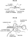
- the liquid injection port is preferably arranged so as to face to a diagonally side direction of an upper side (a ceiling side when operating) as shown in Fig. 5A as seen from a proximal end side of the operation unit, that is, face to a diagonally upward right direction in a case where an operator is a right-handed operator.
- an object of the present invention is to provide a treatment tool for an endoscope which can prevent a screwed portion between an operation unit and a connection unit from being loosened and disconnected by a rotational operation during treatment, and can temporarily fix a direction of a liquid injection port so as to prevent the liquid injection port from moving from a position where a liquid injecting operation is easily performed.
- a treatment tool for an endoscope including an elongated cylindrical flexible sheath, an operation wire which is inserted into a cylinder of the flexible sheath and is movable forward and backward in an axial direction within the cylinder by being operated to be pushed and pulled, a treatment unit which is provided in a distal end of the operation wire and performs treatment of an affected area, an operation unit for operating the operation wire to move forward and backward, a liquid injection unit which is arranged between the flexible sheath and the operation unit and includes a liquid injection port for supplying liquid to the treatment unit, and the liquid injection unit and the operation unit being connected by screw fastening, wherein a locking mechanism is provided for temporarily fixing the screwed state.
- the treatment tool for the endoscope according to the first aspect, wherein the locking mechanism includes a projection which is arranged in the operation unit and protrudes toward a direction of the liquid injection unit, and a projection which is arranged in the liquid injection unit and protrudes toward a direction of the operation unit, and the projection arranged in one of the operation unit and the liquid injection unit climbs over the other projection by the screwing fastening, thereby temporarily fixing.
- the treatment tool for the endoscope according to the second aspect, wherein the projection arranged in one of the operation unit and the liquid injection unit is formed into a semispherical shape, the projection arranged in the other of the operation unit and the liquid unit is formed into a rectangular parallelepiped shape which has a long side which is longer than a diameter of the semispherical projection, and is provided in facing surfaces of the operation unit or the liquid injection unit in such a manner that the long side comes into contact with the semispherical projection during the screwing process.
- the treatment tool for the endoscope according to the first aspect, further including a sheath connection unit which is arranged between the flexible sheathe and the liquid injection unit so as to connect the flexible sheath and the liquid injection unit, and a second locking mechanism which connects the sheath connection unit and the liquid injection unit by screw fastening and temporarily fixes the screwed state.
- the treatment tool for the endoscope according to the second aspect, further including a sheath connection unit which is arranged between the flexible sheathe and the liquid injection unit so as to connect the flexible sheath and the liquid injection unit, and a second locking mechanism which connects the sheath connection unit and the liquid injection unit by screw fastening and temporarily fixes the screwed state.
- the treatment tool for the endoscope according to the third aspect, further including a sheath connection unit which is arranged between the flexible sheath and the liquid injection unit so as to connect the flexible sheath and the liquid injection unit, and a second locking mechanism which connects the sheath connection unit and the liquid injection unit by screw fastening and temporarily fixes the screwed state.
- the treatment tool for the endoscope according to the fourth aspect, wherein the second locking mechanism includes a projection which is arranged in the sheath connection unit and protrudes toward a direction of the liquid injection unit, and a projection which is arranged in the liquid injection unit and protrudes toward a direction of the sheath connection unit, and the projection arranged in one of the operation unit and the liquid injection unit climbs over the other projection by the screwing fastening, thereby temporarily fixing.
- the treatment tool for the endoscope according to the fifth aspect, wherein the second locking mechanism includes a projection which is arranged in the sheath connection unit and protrudes toward a direction of the liquid injection unit, and a projection which is arranged in the liquid injection unit and protrudes toward a direction of the sheath connection unit, and the projection arranged in one of the operation unit and the liquid injection unit climbs over the other projection by the screw fastening, thereby temporarily fixing.
- the treatment tool for the endoscope according to the sixth aspect, wherein the second locking mechanism includes a projection which is arranged in the sheath connection unit and protrudes toward a direction of the liquid injection unit, and a projection which is arranged in the liquid injection unit and protrudes toward a direction of the sheath connection unit, and the projection arranged in one of the operation unit and the liquid injection unit climbs over the other projection by the screwing, thereby temporarily fixing.
- the treatment tool for the endoscope according to the seventh aspect, wherein the projection arranged in one of the sheath connection unit and the liquid injection unit is formed into a semispherical shape, the projection arranged in the other of the sheath connection unit and the liquid injection unit is formed into a rectangular parallelepiped shape which has a long side which is longer than a diameter of the semispherical projection, and is provided in facing surfaces of the sheath connection unit or the liquid injection unit in such a manner that the long side comes into contact with the semispherical projection during the screwing process.
- the treatment tool for the endoscope according to the eighth aspect, wherein the projection arranged in one of the sheath connection unit and the liquid injection unit is formed into a semispherical shape, the projection arranged in the other of the sheath connection unit and the liquid unit is formed into a rectangular parallelepiped shape which has a long side which is longer than a diameter of the semispherical projection, and is provided in facing surfaces of the sheath connection unit or the liquid injection unit in such a manner that the long side comes into contact with the semispherical projection during the screwing process.
- the treatment tool for the endoscope according to the ninth aspect, wherein the projection arranged in one of the sheath connection unit and the liquid injection unit is formed into a semispherical shape, the projection arranged in the other of the sheath connection unit and the liquid unit is formed into a rectangular parallelepiped shape which has a long side which is longer than a diameter of the semispherical projection, and is provided in facing surfaces of the sheath connection unit or the liquid injection unit in such a manner that the long side comes into contact with the semispherical projection during the screwing process.
- the liquid injection unit and the operation unit are connected by screw fastening, and the locking mechanism is provided for temporarily fixing the screwed state. Therefore, it is possible to prevent the screw fastening portion between the liquid injection unit and the operation unit from being loosened and disconnected during the treatment, and it is possible to temporarily fix the direction of the liquid injection port so as to prevent the liquid injection port from moving from the position where the liquid injection operation is easily performed, thereby easily performing the liquid injection operation.
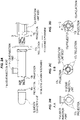
- a treatment tool 1 for an endoscope is provided with an elongated flexible sheath 2 which has an operation unit 10 attached to a proximal end thereof and is made of resin or coil, an operation wire 3 which is inserted into the flexible sheath 2 so as to be movable forward and backward, and a scissors unit 4 which is connected to a distal end of the operation wire 3, is structured such that a pair of distal end electrodes arranged in a distal end of the flexible sheath open and close (open and close in a direction of Y in the drawing) to perform treatment by pushing the operation wire 3 to the distal end side or pulling the operation wire 3 to the proximal end side (operating in a direction of X in the drawing) on the basis of an operation of the operation unit 10 and serves as a treatment unit.
- the operation unit 10, an injection unit 11 and a sheath connection unit 12 are manufactured by a material such as a synthetic resin which is slightly deformable by weight or pressure.
- the treatment unit is constructed by the scissors unit.
- the present invention is not limited to this, but the treatment unit may be constructed by a basket unit which inflates like a basket on the basis of a self-biasing and grips or crushes a foreign substance within the body cavity, and the other treatment units having the other functions.
- a direction toward the operation unit 10 side in the right of Fig. 1 is called as a proximal end side (or a base end side), and a direction toward the scissors unit 4 serving as the treatment unit is called as a distal end side.
- the operation unit 10 is provided with an operation unit body 10a which is arranged in the base end side of the flexible sheath 2 and is gripped by an operator, and a slider 10b which is relatively movable with respect to the operation unit body 10a, and operates the operation wire 3 to move forward and backward by relatively moving the operation unit body 10a and the slider 10b in the direction of X in the drawing, thereby displacing the scissors unit 4 to an open state and a closed state.
- the operation wire 3 is covered in a base end side thereof with a reinforcement pipe 16 ( Fig. 3 ) constructed by a stainless pipe so as to prevent the operation wire 3 from being buckled when operating to press.
- the slider 10b is provided with a power source connection terminal 10c for connecting a high-frequency power source cord, and can apply a high-frequency current to the scissors unit 4 in the distal end through the operation wire 3.
- a liquid injection unit 11 is attached to a distal end of the operation unit 10.
- a cylindrical liquid injection port 11a is open to the liquid injection unit 11 for a liquid supply of a drug solution to the distal end through an internal portion of the flexible sheath 2 by attachment of an injection syringe (not shown) for injecting the liquid.
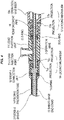
- the liquid injection unit 11 is formed into an approximately cylindrical shape having a through hole in an axial direction as shown in an outer appearance diagram in the operation unit side of Fig. 2A (the sheath 2, the operation wire 3 and a folding prevention tube being not shown) and a cross sectional view of Fig. 3 , and the liquid injection port 11a for injecting the drug solution is formed to be integrally protruded sideward.
- the liquid injection port 11a is provided with a hole in a perpendicular direction to the axis of the liquid injection unit 11 in such a manner as to be connected to a through hole in the axial direction of the liquid injection unit 11.
- a sheath connection unit 12 for connecting the flexible sheath 2 is connected to the liquid injection unit 11 in a distal end thereof.
- a through hole is formed in an axial direction of the sheath connection unit 12, and a sheath base end stand 13 for connecting the flexible sheath 2 is arranged in a distal end of the sheath connection unit 12, as shown in Fig. 3 .
- the flexible sheath 2 is connected and fixed to the sheath base end stand 13.
- Reference numeral 14 denotes a folding prevention tube which is arranged to surround a base end portion of the flexible sheath 2 and is made of an electric insulating material for preventing the base end portion of the flexible sheath 2 from being sharply folded in the vicinity of the connection portion to the sheath connection unit 12 and being damaged
- reference numerals 15, 19 and 20 denote an O-ring for preventing leakage of liquid.
- connection structure for connecting the operation unit 10 and the liquid injection unit 11.
- connection between the operation unit 10 and the liquid injection unit 11 is achieved by a screwing operation between a female thread which is formed in an inner wall of the liquid injection unit 11 in a proximal end side, and a male thread which is formed in an outer periphery of a small diameter portion having a level difference in a distal end of the operation unit body 10a, as shown in Figs. 2A to 4 .
- the female thread and the male thread are previously set in such a manner as to be screwed to a predetermined angle mentioned later.
- connection between the sheath connection unit 12 and the liquid injection unit 11 is achieved by a screwing operation between a female thread which is formed in an inner wall of the sheath connection unit 12 in a proximal end side, and a male thread which is formed in an outer periphery of a small diameter portion having a level difference in a distal end of the liquid injection unit 11, as shown in Figs. 2A to 4 .
- the treatment tool 1 for the endoscope according to the present embodiment is provided with a first locking mechanism 17 for temporarily fixing a screwed state between the liquid injection unit 11 and the operation unit body 10a, and a second locking mechanism 18 for temporarily fixing a screwed state between the liquid injection unit 11 and the sheath connection unit 12.
- a first locking mechanism 17 for temporarily fixing a screwed state between the liquid injection unit 11 and the operation unit body 10a
- a second locking mechanism 18 for temporarily fixing a screwed state between the liquid injection unit 11 and the sheath connection unit 12.
- the first locking mechanism 17 is provided with two semispherical projections 17a which protrude toward a direction of the operation unit body 10a from point symmetrical positions on a circumference of a cylindrical end surface of the liquid injection unit 11, shown in Fig. 2B which is a view as seen from a direction of a line A-A in Fig. 2A , and four rectangular parallelepiped projections 17b which extend radially on a cylindrical end surface corresponding to a level difference portion positioned closer to the proximal end side than the male thread of the operation unit body 10a with a longer long side than a diameter of the projection 17a, and protrude toward a direction of the liquid injection unit 11, shown in Fig. 2C which is a view as seen from a direction of a line B-B in Fig. 2A .
- an end surface of the semispherical projection 17a of the liquid injection unit 11 and an end surface of the operation unit body 10a come close to each other and come into contact by rotating the liquid injection unit 11 in a direction of an arrow P with respect to the operation unit body 10a.
- the first locking mechanism 17 strongly rotates (tightens) in such a manner that the semispherical projection 17a climbs over the rectangular parallelepiped projection 17b (with deforming) while rotating from a state in which the synthetic resin projections 17a and 17b are in contact, so that the rectangular parallelepiped projection 17b prevents rotation in an inverse direction of an arrow Q to the direction of P for tightening, and the operation unit body 10a and the liquid injection unit 11 can be temporarily fixed.
- temporary fixing in the present application means a state in which the temporary fixing is not canceled by the rotation during the treatment, but can be canceled by applying a force in the direction of the arrow Q to rotate and allowing the projection 17a to climb over the projection 17b if the cancel is desired.
- the second locking mechanism 18 is provided with two semispherical projections 18a which protrude toward the direction of the liquid injection unit 11 from point symmetrical positions on the circumference of the cylindrical end surface in the proximal end side of the sheath connection unit 12, and four rectangular parallelepiped projections 18b which extend radially to the cylindrical end surface which is the level difference portion positioned closer to the proximal end side than the male thread of the liquid injection unit 11 with a longer long side than a diameter of the projection 18a, and protrude toward the direction of the sheath connection unit 12, shown in Fig. 2A .
- end surfaces of the semispherical projections 18a of the sheath connection unit 12 comes close to an end surface of the liquid injection unit 11 by rotating and screwing the sheath connection unit 12 with respect to the liquid injection unit 11 in the same manner as the first locking mechanism 17.
- the second locking mechanism 18 strongly rotates (tightens) in such a manner that the semispherical projection 18a climbs over the rectangular parallelepiped projection 18b (with deforming) while rotating from a state in which the synthetic resin projections 18a and 18b are in contact, so that the rectangular parallelepiped projection 17b prevents rotation in an inverse direction of to the direction for tightening, and the sheath connection unit 12 and the liquid injection unit 11 can be temporarily fixed.
- a general right-handed operator faces the back of the right hand to a floor side, puts the thumb on a finger holding portion of the operation unit body 10a, puts the index finger and the middle finger on a finger holding portion of the slider 10b, and moves the operation unit body 10a and the slider 10b relatively in the direction of X in the drawing, in a state in which the power source cord is connected to the power source connection terminal 10c from the floor side, as shown in Fig. 5B , thereby operating the treatment unit which protrudes from the distal end through a channel of the endoscope.
- the treatment tool for the endoscope to be operated requires a strong force for feeding the liquid to the distal end through the narrow elongated sheath when feeding the drug solution to the distal end of the sheath. Therefore, the force applied by a non-dominant hand may be insufficient.
- the operator switches the operation unit 10 from the dominant hand (right hand) to the non-dominant hand (left hand) to hold while facing the power source connection terminal 10c to the floor side in a state shown in Fig. 5B , holds the injection tool by the dominant hand (right hand), and inserts the distal end of the injection tool into the liquid injection port 11a to inject liquid.
- the direction of the liquid injection port 11a preferably faces to the right hand side when holding the operation unit by the left hand in a state in which the power source connection terminal 10c faces to the floor side.
- the direction is preferably set to about 45 degree in a diagonally upward right direction (about 45 degree in a diagonally upward direction in the index finger side when holding by the right hand before supplying liquid), the force of the right hand is easily applied.
- the treatment tool 1 for the endoscope shown in the present embodiment can prevent the screwed portion between the operation unit and the connection unit from being loosened and disconnected, and can temporarily fix the liquid injection port 11a in such a manner that the direction of the liquid injection port 11a do not move from the position where the liquid injection operation mentioned above is easily performed, since the screwed state is temporarily fixed by the locking mechanism. Therefore, the liquid injection operation is easily performed.
- the treatment tool 1 for the endoscope shown in the present embodiment is in no danger of damage due to the deterioration of the adhesive agent since no adhesive agent is used for the locking mechanism. Further, in the treatment tool 1 for the endoscope shown in the present embodiment, when a part of the operation unit is damaged, only the operation unit can be replaced by a new operation unit as is different from a case where the adhesive agent is used. Therefore, it is not necessary to draw a whole of the treatment tool for the endoscope from the endoscope during the treatment and replace a whole of the treatment tool, so that a rapid treatment can be achieved, and a cost reduction can be achieved.
- the locking mechanism is not limited to the embodiment in the number of the semispherical projections or the rectangular parallelepiped projections.
- one projection may be constructed by three semispherical projections, and the other projection may be constructed by three rectangular parallelepiped projections extending in three directions, or the other numbers may be employed.
- the locking mechanism according to the present invention is not limited to the semispherical shape and the rectangular parallelepiped shape, but may be constructed by the other mechanism, for example, constructed by a combination of one projection and the other groove fitted to the projection.
Landscapes
- Health & Medical Sciences (AREA)
- Life Sciences & Earth Sciences (AREA)
- Surgery (AREA)
- Engineering & Computer Science (AREA)
- Public Health (AREA)
- Nuclear Medicine, Radiotherapy & Molecular Imaging (AREA)
- General Health & Medical Sciences (AREA)
- Veterinary Medicine (AREA)
- Biomedical Technology (AREA)
- Heart & Thoracic Surgery (AREA)
- Medical Informatics (AREA)
- Molecular Biology (AREA)
- Animal Behavior & Ethology (AREA)
- Physics & Mathematics (AREA)
- Otolaryngology (AREA)
- Plasma & Fusion (AREA)
- Biophysics (AREA)
- Optics & Photonics (AREA)
- Pathology (AREA)
- Radiology & Medical Imaging (AREA)
- Cardiology (AREA)
- Orthopedic Medicine & Surgery (AREA)
- Vascular Medicine (AREA)
- Endoscopes (AREA)
- Surgical Instruments (AREA)
Applications Claiming Priority (1)
| Application Number | Priority Date | Filing Date | Title |
|---|---|---|---|
| PCT/JP2019/024203 WO2020255278A1 (ja) | 2019-06-19 | 2019-06-19 | 内視鏡用処置具 |
Publications (3)
| Publication Number | Publication Date |
|---|---|
| EP3988041A1 true EP3988041A1 (de) | 2022-04-27 |
| EP3988041A4 EP3988041A4 (de) | 2023-01-11 |
| EP3988041B1 EP3988041B1 (de) | 2024-11-27 |
Family
ID=74040333
Family Applications (1)
| Application Number | Title | Priority Date | Filing Date |
|---|---|---|---|
| EP19934236.1A Active EP3988041B1 (de) | 2019-06-19 | 2019-06-19 | Behandlungswerkzeug für endoskop |
Country Status (6)
| Country | Link |
|---|---|
| US (1) | US12414809B2 (de) |
| EP (1) | EP3988041B1 (de) |
| KR (1) | KR102808986B1 (de) |
| CN (1) | CN113993471A (de) |
| DK (1) | DK3988041T3 (de) |
| WO (1) | WO2020255278A1 (de) |
Families Citing this family (1)
| Publication number | Priority date | Publication date | Assignee | Title |
|---|---|---|---|---|
| WO2025089076A1 (ja) * | 2023-10-23 | 2025-05-01 | 朝日インテック株式会社 | 医療用デバイス |
Family Cites Families (16)
| Publication number | Priority date | Publication date | Assignee | Title |
|---|---|---|---|---|
| US5704914A (en) * | 1996-02-23 | 1998-01-06 | Stocking; John E. | Catheter placement assembly |
| JP4295849B2 (ja) | 1999-02-02 | 2009-07-15 | Hoya株式会社 | 内視鏡用ワイヤループ型処置具 |
| JP4338300B2 (ja) * | 2000-10-23 | 2009-10-07 | Hoya株式会社 | 内視鏡用処置具 |
| JP4611511B2 (ja) | 2000-12-08 | 2011-01-12 | Hoya株式会社 | 内視鏡用チューブ状処置具 |
| JP4806134B2 (ja) | 2001-06-13 | 2011-11-02 | パイロットインキ株式会社 | 筆記具の螺合構造 |
| US20030097146A1 (en) | 2001-11-19 | 2003-05-22 | Scimed Life Systems, Inc. | Endoscopic surgical instrument |
| WO2004037329A1 (ja) * | 2002-10-24 | 2004-05-06 | Terumo Kabushiki Kaisha | シリンジ、キャップおよびプレフィルドシリンジの製造方法 |
| JP5086648B2 (ja) * | 2007-01-19 | 2012-11-28 | オリンパスメディカルシステムズ株式会社 | 処置具 |
| JP5048391B2 (ja) * | 2007-04-27 | 2012-10-17 | 直久 矢作 | 内視鏡用処置具 |
| JP2009233269A (ja) | 2008-03-28 | 2009-10-15 | Fujinon Corp | 内視鏡用高周波処置具 |
| JP5174528B2 (ja) * | 2008-05-15 | 2013-04-03 | Hoya株式会社 | 内視鏡用処置具の操作部 |
| JP2014153461A (ja) * | 2013-02-06 | 2014-08-25 | Konica Minolta Inc | レンズ鏡筒及びカメラモジュール並びにカメラモジュールの製造方法 |
| JP6548034B2 (ja) * | 2013-12-11 | 2019-07-24 | 株式会社ジェイ・エム・エス | オスコネクタ |
| EP3081254B1 (de) * | 2013-12-11 | 2021-01-27 | JMS Co., Ltd. | Stecker |
| CN206093265U (zh) * | 2016-10-11 | 2017-04-12 | 厦门市台亚塑胶有限公司 | 一种水管连接用直接头 |
| JP7129777B2 (ja) * | 2018-01-12 | 2022-09-02 | 清明 本間 | 内視鏡用処置具 |
-
2019
- 2019-06-19 WO PCT/JP2019/024203 patent/WO2020255278A1/ja not_active Ceased
- 2019-06-19 KR KR1020227001651A patent/KR102808986B1/ko active Active
- 2019-06-19 EP EP19934236.1A patent/EP3988041B1/de active Active
- 2019-06-19 DK DK19934236.1T patent/DK3988041T3/da active
- 2019-06-19 CN CN201980097256.XA patent/CN113993471A/zh active Pending
- 2019-06-19 US US17/533,483 patent/US12414809B2/en active Active
Also Published As
| Publication number | Publication date |
|---|---|
| US12414809B2 (en) | 2025-09-16 |
| DK3988041T3 (da) | 2024-12-16 |
| EP3988041A4 (de) | 2023-01-11 |
| WO2020255278A1 (ja) | 2020-12-24 |
| KR20220024650A (ko) | 2022-03-03 |
| EP3988041B1 (de) | 2024-11-27 |
| US20220183739A1 (en) | 2022-06-16 |
| CN113993471A (zh) | 2022-01-28 |
| KR102808986B1 (ko) | 2025-05-15 |
Similar Documents
| Publication | Publication Date | Title |
|---|---|---|
| US10149940B2 (en) | Connector for fluid, and syringe | |
| CN102165650B (zh) | 可旋转调节的连接器组件 | |
| EP3302215B1 (de) | Endoskop | |
| CN109906094B (zh) | 用于固定两个构件之间的可分离联接的系统 | |
| US20050096688A1 (en) | Gripper for catheter shaft | |
| US20140276613A1 (en) | Catheter system | |
| JP7175989B2 (ja) | ワーキングチャネルを延長するためのデバイス | |
| US10328238B2 (en) | Catheter system | |
| US10828053B2 (en) | Medical device handles and related methods | |
| US10300214B2 (en) | Cap assembly for a medicament delivery device | |
| US10716914B2 (en) | Catheter system | |
| EP3988041B1 (de) | Behandlungswerkzeug für endoskop | |
| CN111227928A (zh) | 注射装置、圈套器及医疗设备 | |
| EP4056146A1 (de) | Zahnärztliche düsenvorrichtung | |
| JP7129777B2 (ja) | 内視鏡用処置具 | |
| US7476101B2 (en) | Dental handpiece with removable apex finding electrode | |
| US9775966B2 (en) | Catheter system | |
| CN111870210A (zh) | 内窥镜装置 | |
| TWI809134B (zh) | 內視鏡用處置器具 | |
| CN212416680U (zh) | 扭转辅助工具 | |
| JP4297454B2 (ja) | 内視鏡用穿刺具 | |
| CN220070481U (zh) | 一种电极保护装置 | |
| KR101440379B1 (ko) | 일체형 플런저가 구비된 근관 충전기 | |
| US20240181222A1 (en) | Safety cannula assembly | |
| CN115715718A (zh) | 一种植入物输送装置 |
Legal Events
| Date | Code | Title | Description |
|---|---|---|---|
| STAA | Information on the status of an ep patent application or granted ep patent |
Free format text: STATUS: THE INTERNATIONAL PUBLICATION HAS BEEN MADE |
|
| PUAI | Public reference made under article 153(3) epc to a published international application that has entered the european phase |
Free format text: ORIGINAL CODE: 0009012 |
|
| STAA | Information on the status of an ep patent application or granted ep patent |
Free format text: STATUS: REQUEST FOR EXAMINATION WAS MADE |
|
| 17P | Request for examination filed |
Effective date: 20211209 |
|
| AK | Designated contracting states |
Kind code of ref document: A1 Designated state(s): AL AT BE BG CH CY CZ DE DK EE ES FI FR GB GR HR HU IE IS IT LI LT LU LV MC MK MT NL NO PL PT RO RS SE SI SK SM TR |
|
| DAV | Request for validation of the european patent (deleted) | ||
| DAX | Request for extension of the european patent (deleted) | ||
| A4 | Supplementary search report drawn up and despatched |
Effective date: 20221209 |
|
| RIC1 | Information provided on ipc code assigned before grant |
Ipc: A61B 17/00 20060101ALN20221205BHEP Ipc: A61M 39/10 20060101ALN20221205BHEP Ipc: A61B 18/00 20060101ALN20221205BHEP Ipc: A61B 17/22 20060101ALN20221205BHEP Ipc: A61B 18/14 20060101ALI20221205BHEP Ipc: A61B 18/12 20060101ALI20221205BHEP Ipc: A61B 17/94 20060101AFI20221205BHEP |
|
| STAA | Information on the status of an ep patent application or granted ep patent |
Free format text: STATUS: EXAMINATION IS IN PROGRESS |
|
| 17Q | First examination report despatched |
Effective date: 20231204 |
|
| GRAP | Despatch of communication of intention to grant a patent |
Free format text: ORIGINAL CODE: EPIDOSNIGR1 |
|
| STAA | Information on the status of an ep patent application or granted ep patent |
Free format text: STATUS: GRANT OF PATENT IS INTENDED |
|
| RIC1 | Information provided on ipc code assigned before grant |
Ipc: A61B 17/00 20060101ALN20240621BHEP Ipc: A61M 39/10 20060101ALN20240621BHEP Ipc: A61B 18/00 20060101ALN20240621BHEP Ipc: A61B 17/22 20060101ALN20240621BHEP Ipc: A61B 18/14 20060101ALI20240621BHEP Ipc: A61B 18/12 20060101ALI20240621BHEP Ipc: A61B 17/94 20060101AFI20240621BHEP |
|
| INTG | Intention to grant announced |
Effective date: 20240711 |
|
| GRAS | Grant fee paid |
Free format text: ORIGINAL CODE: EPIDOSNIGR3 |
|
| GRAA | (expected) grant |
Free format text: ORIGINAL CODE: 0009210 |
|
| STAA | Information on the status of an ep patent application or granted ep patent |
Free format text: STATUS: THE PATENT HAS BEEN GRANTED |
|
| AK | Designated contracting states |
Kind code of ref document: B1 Designated state(s): AL AT BE BG CH CY CZ DE DK EE ES FI FR GB GR HR HU IE IS IT LI LT LU LV MC MK MT NL NO PL PT RO RS SE SI SK SM TR |
|
| REG | Reference to a national code |
Ref country code: GB Ref legal event code: FG4D |
|
| REG | Reference to a national code |
Ref country code: CH Ref legal event code: EP |
|
| REG | Reference to a national code |
Ref country code: DK Ref legal event code: T3 Effective date: 20241210 |
|
| REG | Reference to a national code |
Ref country code: IE Ref legal event code: FG4D |
|
| REG | Reference to a national code |
Ref country code: DE Ref legal event code: R096 Ref document number: 602019062794 Country of ref document: DE |
|
| REG | Reference to a national code |
Ref country code: LT Ref legal event code: MG9D |
|
| REG | Reference to a national code |
Ref country code: NL Ref legal event code: MP Effective date: 20241127 |
|
| PG25 | Lapsed in a contracting state [announced via postgrant information from national office to epo] |
Ref country code: PT Free format text: LAPSE BECAUSE OF FAILURE TO SUBMIT A TRANSLATION OF THE DESCRIPTION OR TO PAY THE FEE WITHIN THE PRESCRIBED TIME-LIMIT Effective date: 20250327 Ref country code: HR Free format text: LAPSE BECAUSE OF FAILURE TO SUBMIT A TRANSLATION OF THE DESCRIPTION OR TO PAY THE FEE WITHIN THE PRESCRIBED TIME-LIMIT Effective date: 20241127 Ref country code: IS Free format text: LAPSE BECAUSE OF FAILURE TO SUBMIT A TRANSLATION OF THE DESCRIPTION OR TO PAY THE FEE WITHIN THE PRESCRIBED TIME-LIMIT Effective date: 20250327 |
|
| PG25 | Lapsed in a contracting state [announced via postgrant information from national office to epo] |
Ref country code: FI Free format text: LAPSE BECAUSE OF FAILURE TO SUBMIT A TRANSLATION OF THE DESCRIPTION OR TO PAY THE FEE WITHIN THE PRESCRIBED TIME-LIMIT Effective date: 20241127 Ref country code: NL Free format text: LAPSE BECAUSE OF FAILURE TO SUBMIT A TRANSLATION OF THE DESCRIPTION OR TO PAY THE FEE WITHIN THE PRESCRIBED TIME-LIMIT Effective date: 20241127 |
|
| REG | Reference to a national code |
Ref country code: AT Ref legal event code: MK05 Ref document number: 1744955 Country of ref document: AT Kind code of ref document: T Effective date: 20241127 |
|
| PG25 | Lapsed in a contracting state [announced via postgrant information from national office to epo] |
Ref country code: BG Free format text: LAPSE BECAUSE OF FAILURE TO SUBMIT A TRANSLATION OF THE DESCRIPTION OR TO PAY THE FEE WITHIN THE PRESCRIBED TIME-LIMIT Effective date: 20241127 |
|
| PG25 | Lapsed in a contracting state [announced via postgrant information from national office to epo] |
Ref country code: ES Free format text: LAPSE BECAUSE OF FAILURE TO SUBMIT A TRANSLATION OF THE DESCRIPTION OR TO PAY THE FEE WITHIN THE PRESCRIBED TIME-LIMIT Effective date: 20241127 |
|
| PG25 | Lapsed in a contracting state [announced via postgrant information from national office to epo] |
Ref country code: NO Free format text: LAPSE BECAUSE OF FAILURE TO SUBMIT A TRANSLATION OF THE DESCRIPTION OR TO PAY THE FEE WITHIN THE PRESCRIBED TIME-LIMIT Effective date: 20250227 |
|
| PG25 | Lapsed in a contracting state [announced via postgrant information from national office to epo] |
Ref country code: LV Free format text: LAPSE BECAUSE OF FAILURE TO SUBMIT A TRANSLATION OF THE DESCRIPTION OR TO PAY THE FEE WITHIN THE PRESCRIBED TIME-LIMIT Effective date: 20241127 Ref country code: AT Free format text: LAPSE BECAUSE OF FAILURE TO SUBMIT A TRANSLATION OF THE DESCRIPTION OR TO PAY THE FEE WITHIN THE PRESCRIBED TIME-LIMIT Effective date: 20241127 Ref country code: GR Free format text: LAPSE BECAUSE OF FAILURE TO SUBMIT A TRANSLATION OF THE DESCRIPTION OR TO PAY THE FEE WITHIN THE PRESCRIBED TIME-LIMIT Effective date: 20250228 |
|
| PG25 | Lapsed in a contracting state [announced via postgrant information from national office to epo] |
Ref country code: PL Free format text: LAPSE BECAUSE OF FAILURE TO SUBMIT A TRANSLATION OF THE DESCRIPTION OR TO PAY THE FEE WITHIN THE PRESCRIBED TIME-LIMIT Effective date: 20241127 |
|
| PG25 | Lapsed in a contracting state [announced via postgrant information from national office to epo] |
Ref country code: RS Free format text: LAPSE BECAUSE OF FAILURE TO SUBMIT A TRANSLATION OF THE DESCRIPTION OR TO PAY THE FEE WITHIN THE PRESCRIBED TIME-LIMIT Effective date: 20250227 |
|
| PG25 | Lapsed in a contracting state [announced via postgrant information from national office to epo] |
Ref country code: SM Free format text: LAPSE BECAUSE OF FAILURE TO SUBMIT A TRANSLATION OF THE DESCRIPTION OR TO PAY THE FEE WITHIN THE PRESCRIBED TIME-LIMIT Effective date: 20241127 |
|
| PGFP | Annual fee paid to national office [announced via postgrant information from national office to epo] |
Ref country code: DK Payment date: 20250627 Year of fee payment: 7 |
|
| PG25 | Lapsed in a contracting state [announced via postgrant information from national office to epo] |
Ref country code: EE Free format text: LAPSE BECAUSE OF FAILURE TO SUBMIT A TRANSLATION OF THE DESCRIPTION OR TO PAY THE FEE WITHIN THE PRESCRIBED TIME-LIMIT Effective date: 20241127 |
|
| PG25 | Lapsed in a contracting state [announced via postgrant information from national office to epo] |
Ref country code: RO Free format text: LAPSE BECAUSE OF FAILURE TO SUBMIT A TRANSLATION OF THE DESCRIPTION OR TO PAY THE FEE WITHIN THE PRESCRIBED TIME-LIMIT Effective date: 20241127 |
|
| PG25 | Lapsed in a contracting state [announced via postgrant information from national office to epo] |
Ref country code: SK Free format text: LAPSE BECAUSE OF FAILURE TO SUBMIT A TRANSLATION OF THE DESCRIPTION OR TO PAY THE FEE WITHIN THE PRESCRIBED TIME-LIMIT Effective date: 20241127 |
|
| PG25 | Lapsed in a contracting state [announced via postgrant information from national office to epo] |
Ref country code: CZ Free format text: LAPSE BECAUSE OF FAILURE TO SUBMIT A TRANSLATION OF THE DESCRIPTION OR TO PAY THE FEE WITHIN THE PRESCRIBED TIME-LIMIT Effective date: 20241127 |
|
| PG25 | Lapsed in a contracting state [announced via postgrant information from national office to epo] |
Ref country code: IT Free format text: LAPSE BECAUSE OF FAILURE TO SUBMIT A TRANSLATION OF THE DESCRIPTION OR TO PAY THE FEE WITHIN THE PRESCRIBED TIME-LIMIT Effective date: 20241127 |
|
| REG | Reference to a national code |
Ref country code: DE Ref legal event code: R097 Ref document number: 602019062794 Country of ref document: DE |
|
| PG25 | Lapsed in a contracting state [announced via postgrant information from national office to epo] |
Ref country code: SE Free format text: LAPSE BECAUSE OF FAILURE TO SUBMIT A TRANSLATION OF THE DESCRIPTION OR TO PAY THE FEE WITHIN THE PRESCRIBED TIME-LIMIT Effective date: 20241127 |
|
| PLBE | No opposition filed within time limit |
Free format text: ORIGINAL CODE: 0009261 |
|
| STAA | Information on the status of an ep patent application or granted ep patent |
Free format text: STATUS: NO OPPOSITION FILED WITHIN TIME LIMIT |
|
| REG | Reference to a national code |
Ref country code: CH Ref legal event code: L10 Free format text: ST27 STATUS EVENT CODE: U-0-0-L10-L00 (AS PROVIDED BY THE NATIONAL OFFICE) Effective date: 20251008 |
|
| 26N | No opposition filed |
Effective date: 20250828 |
|
| REG | Reference to a national code |
Ref country code: DE Ref legal event code: R119 Ref document number: 602019062794 Country of ref document: DE |
|
| REG | Reference to a national code |
Ref country code: CH Ref legal event code: H13 Free format text: ST27 STATUS EVENT CODE: U-0-0-H10-H13 (AS PROVIDED BY THE NATIONAL OFFICE) Effective date: 20260127 |
|
| PG25 | Lapsed in a contracting state [announced via postgrant information from national office to epo] |
Ref country code: MC Free format text: LAPSE BECAUSE OF FAILURE TO SUBMIT A TRANSLATION OF THE DESCRIPTION OR TO PAY THE FEE WITHIN THE PRESCRIBED TIME-LIMIT Effective date: 20241127 |
|
| PG25 | Lapsed in a contracting state [announced via postgrant information from national office to epo] |
Ref country code: LU Free format text: LAPSE BECAUSE OF NON-PAYMENT OF DUE FEES Effective date: 20250619 |
|
| GBPC | Gb: european patent ceased through non-payment of renewal fee |
Effective date: 20250619 |
|
| REG | Reference to a national code |
Ref country code: BE Ref legal event code: MM Effective date: 20250630 |
|
| PG25 | Lapsed in a contracting state [announced via postgrant information from national office to epo] |
Ref country code: GB Free format text: LAPSE BECAUSE OF NON-PAYMENT OF DUE FEES Effective date: 20250619 |
|
| PG25 | Lapsed in a contracting state [announced via postgrant information from national office to epo] |
Ref country code: IE Free format text: LAPSE BECAUSE OF NON-PAYMENT OF DUE FEES Effective date: 20250619 Ref country code: DE Free format text: LAPSE BECAUSE OF NON-PAYMENT OF DUE FEES Effective date: 20260101 |
|
| PG25 | Lapsed in a contracting state [announced via postgrant information from national office to epo] |
Ref country code: BE Free format text: LAPSE BECAUSE OF NON-PAYMENT OF DUE FEES Effective date: 20250630 |
|
| PG25 | Lapsed in a contracting state [announced via postgrant information from national office to epo] |
Ref country code: FR Free format text: LAPSE BECAUSE OF NON-PAYMENT OF DUE FEES Effective date: 20250630 |