EP3988196A1 - Élément filtrant avec outil de démontage - Google Patents
Élément filtrant avec outil de démontage Download PDFInfo
- Publication number
- EP3988196A1 EP3988196A1 EP21195198.3A EP21195198A EP3988196A1 EP 3988196 A1 EP3988196 A1 EP 3988196A1 EP 21195198 A EP21195198 A EP 21195198A EP 3988196 A1 EP3988196 A1 EP 3988196A1
- Authority
- EP
- European Patent Office
- Prior art keywords
- area
- end cap
- filter
- filter element
- tool
- Prior art date
- Legal status (The legal status is an assumption and is not a legal conclusion. Google has not performed a legal analysis and makes no representation as to the accuracy of the status listed.)
- Granted
Links
Images



Classifications
-
- B—PERFORMING OPERATIONS; TRANSPORTING
- B01—PHYSICAL OR CHEMICAL PROCESSES OR APPARATUS IN GENERAL
- B01D—SEPARATION
- B01D29/00—Filters with filtering elements stationary during filtration, e.g. pressure or suction filters, not covered by groups B01D24/00 - B01D27/00; Filtering elements therefor
- B01D29/96—Filters with filtering elements stationary during filtration, e.g. pressure or suction filters, not covered by groups B01D24/00 - B01D27/00; Filtering elements therefor in which the filtering elements are moved between filtering operations; Particular measures for removing or replacing the filtering elements; Transport systems for filters
-
- B—PERFORMING OPERATIONS; TRANSPORTING
- B01—PHYSICAL OR CHEMICAL PROCESSES OR APPARATUS IN GENERAL
- B01D—SEPARATION
- B01D29/00—Filters with filtering elements stationary during filtration, e.g. pressure or suction filters, not covered by groups B01D24/00 - B01D27/00; Filtering elements therefor
- B01D29/11—Filters with filtering elements stationary during filtration, e.g. pressure or suction filters, not covered by groups B01D24/00 - B01D27/00; Filtering elements therefor with bag, cage, hose, tube, sleeve or like filtering elements
- B01D29/13—Supported filter elements
- B01D29/15—Supported filter elements arranged for inward flow filtration
-
- B—PERFORMING OPERATIONS; TRANSPORTING
- B25—HAND TOOLS; PORTABLE POWER-DRIVEN TOOLS; MANIPULATORS
- B25B—TOOLS OR BENCH DEVICES NOT OTHERWISE PROVIDED FOR, FOR FASTENING, CONNECTING, DISENGAGING, OR HOLDING
- B25B27/00—Hand tools, specially adapted for fitting together or separating parts or objects whether or not involving some deformation, not otherwise provided for
- B25B27/0035—Hand tools, specially adapted for fitting together or separating parts or objects whether or not involving some deformation, not otherwise provided for for motor-vehicles
- B25B27/0042—Tools for removing or replacing filters or for draining oil; Tools for setting or loosening closure means for radiators, batteries, or the like
-
- B—PERFORMING OPERATIONS; TRANSPORTING
- B01—PHYSICAL OR CHEMICAL PROCESSES OR APPARATUS IN GENERAL
- B01D—SEPARATION
- B01D2201/00—Details relating to filtering apparatus
- B01D2201/24—Tools used for the removal of filters
-
- B—PERFORMING OPERATIONS; TRANSPORTING
- B01—PHYSICAL OR CHEMICAL PROCESSES OR APPARATUS IN GENERAL
- B01D—SEPARATION
- B01D2201/00—Details relating to filtering apparatus
- B01D2201/29—Filter cartridge constructions
- B01D2201/291—End caps
-
- B—PERFORMING OPERATIONS; TRANSPORTING
- B01—PHYSICAL OR CHEMICAL PROCESSES OR APPARATUS IN GENERAL
- B01D—SEPARATION
- B01D2201/00—Details relating to filtering apparatus
- B01D2201/30—Filter housing constructions
- B01D2201/301—Details of removable closures, lids, caps, filter heads
- B01D2201/305—Snap, latch or clip connecting means
-
- B—PERFORMING OPERATIONS; TRANSPORTING
- B01—PHYSICAL OR CHEMICAL PROCESSES OR APPARATUS IN GENERAL
- B01D—SEPARATION
- B01D2201/00—Details relating to filtering apparatus
- B01D2201/40—Special measures for connecting different parts of the filter
- B01D2201/4015—Bayonet connecting means
-
- B—PERFORMING OPERATIONS; TRANSPORTING
- B01—PHYSICAL OR CHEMICAL PROCESSES OR APPARATUS IN GENERAL
- B01D—SEPARATION
- B01D2201/00—Details relating to filtering apparatus
- B01D2201/40—Special measures for connecting different parts of the filter
- B01D2201/4046—Means for avoiding false mounting of different parts
- B01D2201/4053—Means for avoiding false mounting of different parts using keys
-
- B—PERFORMING OPERATIONS; TRANSPORTING
- B01—PHYSICAL OR CHEMICAL PROCESSES OR APPARATUS IN GENERAL
- B01D—SEPARATION
- B01D2201/00—Details relating to filtering apparatus
- B01D2201/40—Special measures for connecting different parts of the filter
- B01D2201/4084—Snap or Seeger ring connecting means
Definitions
- the present invention relates to a filter element that can be used in particular in a liquid filter, such as in a fuel filter or urea filter.
- Liquid filters in particular urea filters, are known from the prior art. These have a filter body that is usually made of an unstable material such as paper.
- the filter body usually has a hollow cylindrical shape and is provided with end caps. If the filter is used, for example on a vehicle, the filter is located within a housing, with the end caps sealing the filter to the housing, so that a liquid can get into the interior of the filter and then be filtered through the filter body. to leave the housing again on a peripheral surface.
- the filter If the filter is to be removed from the housing, there is a risk that the filter body will be damaged and torn off, so that only part of the filter can be removed. The part remaining in the housing must then be removed with great effort. This problem is exacerbated by the fact that the filter comes into contact with liquids during use, so that the filter swells and the filter has an adhesive effect and static friction on the housing wall.
- a filter element with the features of claim 1 according to the present invention comprises a hollow, in particular hollow-cylindrical, filter body.
- the filter body is preferably made of a cellulose layer that is impregnated with an epoxy resin and combined with a meltblown, in particular made of polymers.
- the filter element comprises at least one, in particular ring-shaped, end cap. The end cap is arranged at an axial end of the filter element, advantageously fixed to the filter element.
- the filter element particularly preferably has two end caps which are each fastened to an axial end of the filter body. Both end caps are advantageously made of plastic, for example polypropylene.
- the end cap has a grommet portion with a first inner diameter and an engagement portion with a second inner diameter. Both the passage area and the engagement area are advantageously arranged on the end cap.
- the end cap has the first inner diameter at the lead-through area, while the end cap has the second inner diameter at the engagement area. It is provided that the first inner diameter is larger than the second inner diameter.
- a tool can be passed through the lead-through area and can be brought into engagement with the end cap at the engagement area.
- the filter element according to the invention thus has the advantage that a tool can be passed through the entire filter element in order in particular to grip that end cap which is arranged furthest within a housing.
- force is not transmitted via the filter body, but rather from the tool via the end cap arranged furthest in the housing with respect to a direction of insertion of the filter element into a filter housing to the filter body.
- a destruction of the filter body is thus excluded and any static friction of the filter to a housing can be overcome.
- This preferably also applies when the filter element does not have an inner support tube that connects the two end caps to one another. So if, in other words, the end caps are only connected to each other by the filter body itself.
- Such filters without a support element can be produced particularly inexpensively.
- the filter body must be attached to the
- the end cap closest to a pull-out opening of the filter housing can withstand the tensile forces alone, which can lead to the filter body rupturing internally, especially if the filter body is damp or saturated with liquid.
- the filter body is only subjected to compressive forces when it is pulled out by means of the tool. If it is damaged when it is pulled out, the damaged parts of the filter body are removed during the pull-out process through the end cap that is furthest away from the pull-out opening and which is pulled using the tool.
- the hollow filter body is preferably a circular cylinder.
- the filter body has an outer filter body circular diameter on its outside and an inner filter body circular diameter.
- the inner circle diameter of the filter body corresponds to the circle diameter of the hollow inner cylinder of the filter body.
- the hollow inner cylinder is preferably circular-cylindrical.
- the first inner diameter of the end cap preferably corresponds to the circular diameter of the circular cylinder, in particular of the hollow inner circular-cylindrical cylinder of the filter body.
- the lead-through area thus has the same circular diameter as the filter body.
- the second inside diameter is preferably also a circle diameter, in particular concentric to the first circle diameter.
- a key-lock arrangement between the end cap and the tool can thus be implemented in a simple manner.
- the circular cylinder can in particular have a surface structure, such as particularly preferably a wave shape running in the radial direction. Such a wave form can arise in the cross section through the star-shaped folded filter material of the filter body.
- the engagement area preferably has a trough shape.
- a tool can be positively connected to the engagement area by inserting the tool into the trough shape.
- the engagement area allows not only the transmission of axial forces from the tool to the filter element, but also the transmission of rotational forces.
- the lead-through area is arranged in the circumferential direction next to the engagement area. It is thus possible for a tool to be able to be passed through the filter element, this being done within the grip area or the lead-through area. After passing the tool through the filter element, the tool can be rotated to abut the engagement area.
- the end cap is preferably embodied symmetrically. It is provided in particular that the end cap has at least two lead-through areas and at least two engagement areas.
- the symmetry of the end cap is in particular a point symmetry about the central axis of the hollow-cylindrical filter body.
- the end cap is therefore constructed in particular in a rotationally symmetrical manner.
- the engagement portion preferably includes a projection.
- the projection is directed radially inwards and thus in the direction of the central axis.
- the second inner diameter is provided on the protrusion.
- the end cap particularly advantageously has a tool-receiving area on which the end cap has the first inner diameter. It is provided that the lead-through area corresponds to a sub-area of the tool-receiving area.
- the projection is arranged on the tool receiving area and thus stands out from the lead-through area.
- the lead-through area and the engagement area are advantageously arranged directly adjacent to one another. A tool can thus be guided very easily through the lead-through area in order to subsequently reach the engagement area by rotation.
- the filter element preferably also has a damping element, the damping element being fastened to a fastening region of the end cap.
- the attachment takes place in particular in a form-fitting manner.
- the damping element particularly advantageously has at least one latching element, so that the damping element can be latched onto the end cap.
- the damping element is made of an elastic material, preferably rubber.
- the end cap also has a ramped area.
- the ramped portion preferably extends axially away from the filter body, while at the same time the ramped portion extends circumferentially from the engagement portion to the lead-through portion. If there are several engagement areas and lead-through areas, the ramp area runs from an engagement area to a lead-through area, with the engagement area and the lead-through area, between which the ramp area extends, not being arranged directly adjacent. Insertion of the tool is facilitated by the ramp area, since it can be inserted at any point in the filter element. The tool is automatically guided through the ramp area to the lead-through area by a force in the axial direction.
- the ramp area is particularly advantageously arranged in such a way that it sweeps over the same area of the end cap in the circumferential direction as the fastening area.
- the ramp area is in particular arranged closer to the filter body than the fastening area. This prevents the tool being inserted into the filter element from detaching the damping element from the end cap. In particular, there is a risk that the connection between the damping element and end cap will be released when the tool is pushed into the filter element, in that the tool presses on the latching element of the damping element. This is effectively prevented by the described arrangement of the ramp area.
- the tool When the tool is inserted into the filter body, the tool first reaches the ramp area of the end cap before the tool reaches the attachment area of the end cap.
- the ramp area guides the tool to the lead-through area, so that it prevents the fastening area from being reached and the damping element from being released.
- the tool receiving area and the fastening area are arranged alternately in the circumferential direction of the end cap.
- the tool receiving area and the fastening area are arranged next to one another.
- the Damping element at a position which is axially above the tool receiving area has a, in particular kidney-shaped, recess.
- the recess is preferably a through opening.
- the tool can thus also be passed through the damping element, which prevents the damping element from being unintentionally released from the end cap by the tool.
- the tool can be rotated within the recess of the damping element in order to move from the lead-through area to the engagement area.
- the invention further relates to a liquid filter.
- the liquid filter is in particular a fuel filter or a urea filter and is particularly advantageously suitable for use in motor vehicles with internal combustion engines.
- the liquid filter includes a filter element as previously described and a housing.
- the filter element is arranged in the housing, with the housing having one, in particular at most one, opening, via which the filter element can be inserted into the housing or removed from the housing.
- the housing is configured as a hollow cylinder, in particular a circular cylinder, with one end face of the hollow cylinder of the housing being at least partially closed, in particular in such a way that the filter element cannot be removed through the side of the housing that has this end face.
- inlet sockets and/or outlet sockets for liquid can be provided on this end face.
- the filter element can thus only be inserted into the hollow cylinder via the remaining end face. It can be seen that at least one end cap cannot be reached directly.
- the filter element according to the invention is advantageous here, since the end cap that is located furthest within the housing in the axial direction can be gripped with a tool.
- the invention includes an arrangement comprising a filter element as described above and a tool. Provision is made for the tool to be able to be inserted into the filter element, the tool being able to be passed through the lead-through area and engaged at the engagement area with the end cap of the filter element, preferably the end cap remote from the opening. In this way, the filter element can be gripped by the tool, so that the filter element can be removed from a housing.
- the tool has at least one engagement element which advantageously complementary in shape to the engaging portion of the end cap.
- a form fit can be produced between the tool and the end cap, with the form fit acting at least in one axial direction and in both circumferential directions.
- FIG 1 shows a filter element 1 according to an embodiment of the invention.
- the filter element 1 comprises a filter body 2 and an annular end cap 3.
- the end cap 3 is arranged at an axial end of the filter body 2, the filter body 2 having a hollow cylindrical shape Has shape, which is circular-cylindrical here. For this reason, all directional information relating to the hollow cylinder is given below.
- the filter element 1 also has an additional second end cap 17 which is arranged axially on an end of the filter body 2 opposite the end cap 3 .
- the additional second end cap 17 is not considered further within the scope of this invention.
- the second additional end cap 17 is ring-shaped and has an inside diameter that corresponds at least to the maximum inside diameter of the end cap 3 .
- the filter element 1 has no support tube in a hollow inner circular cylinder of the filter body 2 .
- the two end caps 3 , 17 are only connected to one another by the filter body 2 .
- the filter element can be produced in a particularly simple and cost-effective manner.
- filter elements 1 are also conceivable in which a support tube, for example made of plastic, is provided in the hollow interior of the filter body 2, preferably a support tube which is not firmly connected to the end caps 3, 17 and only absorbs radial forces of the filter body 2 absorbs and thus prevents the filter body 2 from collapsing.
- the filter body 2 has an outer filter body diameter on its outside and an inner filter body diameter which corresponds to the diameter of the hollow, circular inner cylinder in the filter body 2 .
- the end cap 3 has a tool receiving area 6 .
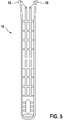
- the tool receiving area 6 serves to guide a tool 10 through (cf figure 4 and figure 5 ), wherein the tool receiving area 6 is divided into two sub-areas. This is detailed out figure 2 evident.
- FIG 2 shows a schematic sectional view through the end cap 3 and through a damping element 7.
- End cap 3 and damping element 7 are shown in an exploded view.
- the end cap 3 has the tool receiving area 6 which is divided into a lead-through area 4 and an engagement area 5 .
- the lead-through area 4 corresponds to a point at which the end cap 3 has a first inner diameter.
- the first inside diameter is particularly advantageously a maximum inside diameter of the end cap 3
- Engagement area 5 is an area where the end cap 3 has a second inner diameter, the first inner diameter being larger than the second inner diameter.
- the engagement area 5 is formed in that a projection 15 pointing radially inward is attached to the tool receiving area 6 .
- the engagement area 5 preferably has a trough shape, so that the tool 10 can be brought into engagement in the engagement area 5 with a form fit.
- a tool 10 can be seen with which the filter element 1 can be gripped.
- the tool 10 has two engagement elements 12 which are designed in a form complementary to the shape of the engagement areas 5 .
- the tool 10 can thus be passed through the entire filter element 1 , the tool 10 being able to be passed through the end cap 3 only in the lead-through region 4 due to the engagement elements 12 . Then the tool 10 can be rotated, this in the case of figure 2 corresponds to a counterclockwise rotation. The engagement elements 12 can then be positively connected to the engagement area 5 . The filter element 1 can thus be removed from a housing 11 .
- a liquid filter 14 is shown, which the filter element 1 from figure 1 comprises, which is arranged within a housing 11.
- the housing 11 has the shape of a hollow cylinder, with one end face of the hollow cylinder being completely closed except for an inlet opening 16 .
- the filter element 1 In order to remove the filter element 1, it must be pulled out through an opening (not shown) within the other end face of the housing 11, not shown.
- a tensile force is applied to the additional end cap 4 in the axial direction, there is a risk that the filter body 2 will be damaged and torn off, so that the end cap 3 remains inside the housing 11 . This can be prevented by the tool 10 since the end cap 3 can be gripped with the tool 10 .
- the tool 10 allows the filter element 1 to rotate within the housing 11 due to the positive connection between the engagement elements 12 and the engagement area 4 . This is particularly helpful when the filter element 1 on the due to static friction Housing 11 adheres.
- figure 6 1 shows how the tool 10 is inserted into the filter element 1, with the engagement elements 12 engaging in the engagement areas 5. FIG. In this position, torque can be transmitted from the tool 10 to the filter element 1 .
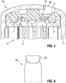
- figure 3 shows that in figure 2 damping element 7 shown in a position connected to the end cap 3 .
- the connection between the end cap 3 and the damping element 7 can be implemented via a fastening area 8 of the end cap and via a respective latching element 13 of the damping element 7 .
- a form-fitting connection between end cap and damping element 7 can be produced by fastening area 8 and latching element 13, as shown in FIG figure 3 is evident.
- the number of ramp areas 9 advantageously corresponds to the number of tool receiving areas 6.
- the ramp area 9 has several advantages: On the one hand, the ramp area 9 can prevent the tool from removing the damping element 7 from the end cap 3 . Furthermore, the ramp area 9 ensures that the tool is always guided to the lead-through area 4 . For this purpose, the ramp area 9 runs in the axial direction away from the filter body 2 and in the circumferential direction from an engagement area 5 to an opposite passage area 4.
- the tool 10 can thus be inserted at any point of the filter element 1, with an axial force acting on the tool 10 this rests against the ramp area 9 and is conducted through the ramp area 9 directly to the lead-through area 4 .
- the tool 10 can never reach the attachment area 8 , which prevents the tool 10 from detaching the locking element 13 from the attachment area 8 .
- the damping element 7 also has recesses at those points that are located axially adjacent to the tool receiving areas 6 of the end cap 3 .
- the recesses are in particular kidney-shaped and advantageously through openings.
- the tool 10 can be passed through the end cap 3 as well as through the damping element 7 in the lead-through region 4 .
- the tool 10 can be rotated when the engagement element 12 is located within the recess of the damping element, in order to guide the engagement element 12 from the lead-through area 4 to the engagement area 5 . This prevents the damping element 7 from being accidentally released from the end cap 3 .
- the recesses also allow the liquid to be filtered to be passed through the damping element 7.
- the filter element 1 can be damped with the damping element 7 so that the filter element 1 can also be operated at low temperatures. If the filter element 1 is operated at low temperatures, there is a risk that liquids to be filtered will freeze.
- the filter element 1 can compensate when the freezing liquid increases in volume.
- the damping element 7 is preferably made of an elastic material, so that it can counteract the volume expansion of the liquid by deformation. A destruction of the filter element 1 or the housing 11 by freezing liquid is thus excluded.
Landscapes
- Chemical & Material Sciences (AREA)
- Chemical Kinetics & Catalysis (AREA)
- Engineering & Computer Science (AREA)
- Mechanical Engineering (AREA)
- Filtration Of Liquid (AREA)
- Filtering Of Dispersed Particles In Gases (AREA)
- Separation Using Semi-Permeable Membranes (AREA)
- Lubrication Details And Ventilation Of Internal Combustion Engines (AREA)
Applications Claiming Priority (3)
| Application Number | Priority Date | Filing Date | Title |
|---|---|---|---|
| DE102015207565.6A DE102015207565B4 (de) | 2015-04-24 | 2015-04-24 | Filterelement, Flüssigkeitsfilter und Anordnung |
| PCT/EP2016/057337 WO2016169754A1 (fr) | 2015-04-24 | 2016-04-04 | Élément filtrant équipé d'un élément d'enlèvement |
| EP16714405.4A EP3285902B1 (fr) | 2015-04-24 | 2016-04-04 | Element filtrant avec outil de demontage |
Related Parent Applications (1)
| Application Number | Title | Priority Date | Filing Date |
|---|---|---|---|
| EP16714405.4A Division EP3285902B1 (fr) | 2015-04-24 | 2016-04-04 | Element filtrant avec outil de demontage |
Publications (2)
| Publication Number | Publication Date |
|---|---|
| EP3988196A1 true EP3988196A1 (fr) | 2022-04-27 |
| EP3988196B1 EP3988196B1 (fr) | 2025-03-26 |
Family
ID=55661434
Family Applications (2)
| Application Number | Title | Priority Date | Filing Date |
|---|---|---|---|
| EP16714405.4A Active EP3285902B1 (fr) | 2015-04-24 | 2016-04-04 | Element filtrant avec outil de demontage |
| EP21195198.3A Active EP3988196B1 (fr) | 2015-04-24 | 2016-04-04 | Element filtrant avec outil de demontage |
Family Applications Before (1)
| Application Number | Title | Priority Date | Filing Date |
|---|---|---|---|
| EP16714405.4A Active EP3285902B1 (fr) | 2015-04-24 | 2016-04-04 | Element filtrant avec outil de demontage |
Country Status (5)
| Country | Link |
|---|---|
| EP (2) | EP3285902B1 (fr) |
| CN (1) | CN107530602B (fr) |
| DE (1) | DE102015207565B4 (fr) |
| ES (2) | ES2901889T3 (fr) |
| WO (1) | WO2016169754A1 (fr) |
Cited By (1)
| Publication number | Priority date | Publication date | Assignee | Title |
|---|---|---|---|---|
| WO2024074598A1 (fr) * | 2022-10-07 | 2024-04-11 | Mann+Hummel Gmbh | Filtre, élément filtrant qui peut être déverrouillé au moyen d'une poignée, poignée pour retirer un élément filtrant, et procédé de désinstallation d'un filtre |
Families Citing this family (8)
| Publication number | Priority date | Publication date | Assignee | Title |
|---|---|---|---|---|
| DE102016223456B4 (de) | 2016-11-25 | 2018-11-08 | Robert Bosch Gmbh | Demontagewerkzeug für einen Filtereinsatz eines Flüssigkeitsfilters |
| DE102017205242B4 (de) | 2017-03-28 | 2022-02-17 | Robert Bosch Gmbh | Demontagewerkzeug für einen Filtereinsatz eines Flüssigkeitsfilters |
| DE102017205237B4 (de) | 2017-03-28 | 2022-02-17 | Robert Bosch Gmbh | Demontagewerkzeug für einen Filtereinsatz eines Flüssigkeitsfilters |
| EP3520871B1 (fr) * | 2018-01-31 | 2021-11-24 | Hengst SE | Cartouche de filtre et porte-filtre pour la cartouche de filtre |
| TWI691357B (zh) * | 2018-10-12 | 2020-04-21 | 旭然國際股份有限公司 | 鑰部結構以及具有前述鑰部結構之過濾裝置 |
| US20220288511A1 (en) * | 2019-07-25 | 2022-09-15 | Rt-Filtertechnik Gmbh | Filter device |
| GB2593427B (en) * | 2019-12-16 | 2022-04-27 | Delphi Tech Ip Ltd | Kit for replacing a jet filter arranged in an engine fuel pump |
| EP3928850B1 (fr) | 2020-06-26 | 2026-01-28 | MANN+HUMMEL GmbH | Élément de filtre avec fixations à un boîtier de filtre présentant une meilleure protection contre les dommages pendant l'installation |
Citations (8)
| Publication number | Priority date | Publication date | Assignee | Title |
|---|---|---|---|---|
| DE4415890A1 (de) * | 1994-05-05 | 1995-11-09 | Knecht Filterwerke Gmbh | Verfahren zum Herausnehmen eines Filterelements |
| EP1008375A1 (fr) * | 1998-12-11 | 2000-06-14 | Baldwin Filters, Inc. | Ensemble de filtre à carburant et couvercle jetable |
| EP1618937A1 (fr) * | 2003-04-28 | 2006-01-25 | Mykrolis Corporation | Outil de demontage d'element filtrant |
| US20100176046A1 (en) * | 2009-01-12 | 2010-07-15 | Mechanical Manufacturing Corp. | Filtration system with a dual sealing ring filter basket and/or a dual sealing ring collar for a filter element |
| US20140044612A1 (en) * | 2012-08-09 | 2014-02-13 | Caterpillar Inc. | After-Treatment System |
| EP2764901A1 (fr) * | 2013-02-07 | 2014-08-13 | Parker Hannifin Corporation | Filetage claveté sur un élément de filtre vissable |
| JP5571865B1 (ja) * | 2013-12-25 | 2014-08-13 | 株式会社小松製作所 | フィルタ取外工具 |
| US20140284265A1 (en) * | 2011-12-08 | 2014-09-25 | Norbert Sann | Filter device |
Family Cites Families (3)
| Publication number | Priority date | Publication date | Assignee | Title |
|---|---|---|---|---|
| DE19828321A1 (de) | 1998-06-25 | 1999-12-30 | Bosch Gmbh Robert | Filtereinsatz in Sternbauart und Verfahren zu seiner Herstellung |
| DE102010043836A1 (de) * | 2010-11-04 | 2012-05-10 | Hengst Gmbh & Co. Kg | Filter mit einem austauschbaren Filtereinsatz |
| DE202011104686U1 (de) * | 2011-08-18 | 2011-12-19 | Mahle International Gmbh | Flüssigkeitsfilter, insbesondere ein Ölfilter |
-
2015
- 2015-04-24 DE DE102015207565.6A patent/DE102015207565B4/de active Active
-
2016
- 2016-04-04 WO PCT/EP2016/057337 patent/WO2016169754A1/fr not_active Ceased
- 2016-04-04 ES ES16714405T patent/ES2901889T3/es active Active
- 2016-04-04 EP EP16714405.4A patent/EP3285902B1/fr active Active
- 2016-04-04 ES ES21195198T patent/ES3032389T3/es active Active
- 2016-04-04 CN CN201680023496.1A patent/CN107530602B/zh active Active
- 2016-04-04 EP EP21195198.3A patent/EP3988196B1/fr active Active
Patent Citations (8)
| Publication number | Priority date | Publication date | Assignee | Title |
|---|---|---|---|---|
| DE4415890A1 (de) * | 1994-05-05 | 1995-11-09 | Knecht Filterwerke Gmbh | Verfahren zum Herausnehmen eines Filterelements |
| EP1008375A1 (fr) * | 1998-12-11 | 2000-06-14 | Baldwin Filters, Inc. | Ensemble de filtre à carburant et couvercle jetable |
| EP1618937A1 (fr) * | 2003-04-28 | 2006-01-25 | Mykrolis Corporation | Outil de demontage d'element filtrant |
| US20100176046A1 (en) * | 2009-01-12 | 2010-07-15 | Mechanical Manufacturing Corp. | Filtration system with a dual sealing ring filter basket and/or a dual sealing ring collar for a filter element |
| US20140284265A1 (en) * | 2011-12-08 | 2014-09-25 | Norbert Sann | Filter device |
| US20140044612A1 (en) * | 2012-08-09 | 2014-02-13 | Caterpillar Inc. | After-Treatment System |
| EP2764901A1 (fr) * | 2013-02-07 | 2014-08-13 | Parker Hannifin Corporation | Filetage claveté sur un élément de filtre vissable |
| JP5571865B1 (ja) * | 2013-12-25 | 2014-08-13 | 株式会社小松製作所 | フィルタ取外工具 |
Cited By (1)
| Publication number | Priority date | Publication date | Assignee | Title |
|---|---|---|---|---|
| WO2024074598A1 (fr) * | 2022-10-07 | 2024-04-11 | Mann+Hummel Gmbh | Filtre, élément filtrant qui peut être déverrouillé au moyen d'une poignée, poignée pour retirer un élément filtrant, et procédé de désinstallation d'un filtre |
Also Published As
| Publication number | Publication date |
|---|---|
| EP3285902A1 (fr) | 2018-02-28 |
| DE102015207565A1 (de) | 2016-10-27 |
| CN107530602A (zh) | 2018-01-02 |
| WO2016169754A1 (fr) | 2016-10-27 |
| ES2901889T3 (es) | 2022-03-24 |
| ES3032389T3 (en) | 2025-07-18 |
| EP3988196B1 (fr) | 2025-03-26 |
| CN107530602B (zh) | 2020-05-12 |
| EP3285902B1 (fr) | 2021-10-06 |
| DE102015207565B4 (de) | 2020-06-18 |
Similar Documents
| Publication | Publication Date | Title |
|---|---|---|
| EP3285902B1 (fr) | Element filtrant avec outil de demontage | |
| DE102007008066B4 (de) | Fitting | |
| DE112008004188B4 (de) | Befestigungsstruktur mit einer Durchgangstülle | |
| EP2265851B1 (fr) | Dispositif d'accouplement | |
| EP2873894A1 (fr) | Bouchon de fermeture | |
| DE102011118099A1 (de) | Vorrichtung zum Verbinden zweier Leitungsabschnitte | |
| DE102014108563B3 (de) | Abgasrohr, Abgasrohrsystem sowie Montageverfahren | |
| EP0545037A1 (fr) | Dispositif d'accouplement de deux conduites, en particulier pour des conduites de carburant | |
| WO2011120797A1 (fr) | Dispositif de raccordement, dispositif de dégazage de carter de vilebrequin et installation d'air frais | |
| DE102007042034A1 (de) | Befestigungssystem zum Befestigen von Bauelementen, insbesondere für Kraftfahrzeuge | |
| DE102013213514A1 (de) | Sicherungsvorrichtung zum Sichern einer Mutter gegen ungewolltes Losdrehen, sowie Lageranordnung einer Welle | |
| WO2018077665A1 (fr) | Système de fixation | |
| DE60026946T2 (de) | Mittel zum Andrücken einer Welle an einen Gabelkopf einer Lenkvorrichtung | |
| EP1925351B1 (fr) | Élément de filtration pour un plateau filtrant de presse | |
| EP3434953B1 (fr) | Bague de sécurité, système de tube de gaz d'échappement pourvu de bague de sécurité | |
| EP1006307A1 (fr) | Raccord enfichable | |
| DE102011086272A1 (de) | Massivkäfig | |
| DE102016119519A1 (de) | Lenksäulenmodul für ein Fahrzeug, Lenksäulenanordnung, Fahrzeug und Verfahren zum Zusammenbau einer Lenksäulenanordnung | |
| EP2982893B1 (fr) | Dispositif de serrage de tuyau | |
| DE102009059844A1 (de) | Radnabe mit getriebeseitigem Schraubenanschlag | |
| EP2982894B1 (fr) | Dispositif de serrage de tuyau | |
| WO2018197113A1 (fr) | Pompe à carburant | |
| DE102015118887A1 (de) | Axialsicherungsanordnung und Axialsicherungsverfahren | |
| DE102016209728A1 (de) | Batteriepolklemme | |
| DE102022206571A1 (de) | Fluidanschlusseinrichtung |
Legal Events
| Date | Code | Title | Description |
|---|---|---|---|
| STAA | Information on the status of an ep patent application or granted ep patent |
Free format text: STATUS: UNKNOWN |
|
| PUAI | Public reference made under article 153(3) epc to a published international application that has entered the european phase |
Free format text: ORIGINAL CODE: 0009012 |
|
| STAA | Information on the status of an ep patent application or granted ep patent |
Free format text: STATUS: THE APPLICATION HAS BEEN PUBLISHED |
|
| AC | Divisional application: reference to earlier application |
Ref document number: 3285902 Country of ref document: EP Kind code of ref document: P |
|
| AK | Designated contracting states |
Kind code of ref document: A1 Designated state(s): AL AT BE BG CH CY CZ DE DK EE ES FI FR GB GR HR HU IE IS IT LI LT LU LV MC MK MT NL NO PL PT RO RS SE SI SK SM TR |
|
| STAA | Information on the status of an ep patent application or granted ep patent |
Free format text: STATUS: REQUEST FOR EXAMINATION WAS MADE |
|
| 17P | Request for examination filed |
Effective date: 20221027 |
|
| RBV | Designated contracting states (corrected) |
Designated state(s): AL AT BE BG CH CY CZ DE DK EE ES FI FR GB GR HR HU IE IS IT LI LT LU LV MC MK MT NL NO PL PT RO RS SE SI SK SM TR |
|
| P01 | Opt-out of the competence of the unified patent court (upc) registered |
Effective date: 20230509 |
|
| STAA | Information on the status of an ep patent application or granted ep patent |
Free format text: STATUS: EXAMINATION IS IN PROGRESS |
|
| 17Q | First examination report despatched |
Effective date: 20230711 |
|
| GRAP | Despatch of communication of intention to grant a patent |
Free format text: ORIGINAL CODE: EPIDOSNIGR1 |
|
| STAA | Information on the status of an ep patent application or granted ep patent |
Free format text: STATUS: GRANT OF PATENT IS INTENDED |
|
| INTG | Intention to grant announced |
Effective date: 20241113 |
|
| GRAJ | Information related to disapproval of communication of intention to grant by the applicant or resumption of examination proceedings by the epo deleted |
Free format text: ORIGINAL CODE: EPIDOSDIGR1 |
|
| STAA | Information on the status of an ep patent application or granted ep patent |
Free format text: STATUS: EXAMINATION IS IN PROGRESS |
|
| GRAP | Despatch of communication of intention to grant a patent |
Free format text: ORIGINAL CODE: EPIDOSNIGR1 |
|
| STAA | Information on the status of an ep patent application or granted ep patent |
Free format text: STATUS: GRANT OF PATENT IS INTENDED |
|
| GRAS | Grant fee paid |
Free format text: ORIGINAL CODE: EPIDOSNIGR3 |
|
| INTC | Intention to grant announced (deleted) | ||
| GRAA | (expected) grant |
Free format text: ORIGINAL CODE: 0009210 |
|
| STAA | Information on the status of an ep patent application or granted ep patent |
Free format text: STATUS: THE PATENT HAS BEEN GRANTED |
|
| INTG | Intention to grant announced |
Effective date: 20250124 |
|
| AC | Divisional application: reference to earlier application |
Ref document number: 3285902 Country of ref document: EP Kind code of ref document: P |
|
| AK | Designated contracting states |
Kind code of ref document: B1 Designated state(s): AL AT BE BG CH CY CZ DE DK EE ES FI FR GB GR HR HU IE IS IT LI LT LU LV MC MK MT NL NO PL PT RO RS SE SI SK SM TR |
|
| REG | Reference to a national code |
Ref country code: GB Ref legal event code: FG4D Free format text: NOT ENGLISH |
|
| REG | Reference to a national code |
Ref country code: CH Ref legal event code: EP |
|
| REG | Reference to a national code |
Ref country code: DE Ref legal event code: R096 Ref document number: 502016016933 Country of ref document: DE |
|
| REG | Reference to a national code |
Ref country code: IE Ref legal event code: FG4D Free format text: LANGUAGE OF EP DOCUMENT: GERMAN |
|
| PG25 | Lapsed in a contracting state [announced via postgrant information from national office to epo] |
Ref country code: RS Free format text: LAPSE BECAUSE OF FAILURE TO SUBMIT A TRANSLATION OF THE DESCRIPTION OR TO PAY THE FEE WITHIN THE PRESCRIBED TIME-LIMIT Effective date: 20250626 |
|
| PG25 | Lapsed in a contracting state [announced via postgrant information from national office to epo] |
Ref country code: FI Free format text: LAPSE BECAUSE OF FAILURE TO SUBMIT A TRANSLATION OF THE DESCRIPTION OR TO PAY THE FEE WITHIN THE PRESCRIBED TIME-LIMIT Effective date: 20250326 |
|
| PGFP | Annual fee paid to national office [announced via postgrant information from national office to epo] |
Ref country code: DE Payment date: 20250624 Year of fee payment: 10 |
|
| PGFP | Annual fee paid to national office [announced via postgrant information from national office to epo] |
Ref country code: ES Payment date: 20250507 Year of fee payment: 10 |
|
| REG | Reference to a national code |
Ref country code: LT Ref legal event code: MG9D |
|
| PG25 | Lapsed in a contracting state [announced via postgrant information from national office to epo] |
Ref country code: NO Free format text: LAPSE BECAUSE OF FAILURE TO SUBMIT A TRANSLATION OF THE DESCRIPTION OR TO PAY THE FEE WITHIN THE PRESCRIBED TIME-LIMIT Effective date: 20250626 |
|
| PG25 | Lapsed in a contracting state [announced via postgrant information from national office to epo] |
Ref country code: HR Free format text: LAPSE BECAUSE OF FAILURE TO SUBMIT A TRANSLATION OF THE DESCRIPTION OR TO PAY THE FEE WITHIN THE PRESCRIBED TIME-LIMIT Effective date: 20250326 |
|
| PG25 | Lapsed in a contracting state [announced via postgrant information from national office to epo] |
Ref country code: LV Free format text: LAPSE BECAUSE OF FAILURE TO SUBMIT A TRANSLATION OF THE DESCRIPTION OR TO PAY THE FEE WITHIN THE PRESCRIBED TIME-LIMIT Effective date: 20250326 |
|
| PGFP | Annual fee paid to national office [announced via postgrant information from national office to epo] |
Ref country code: FR Payment date: 20250516 Year of fee payment: 10 |
|
| REG | Reference to a national code |
Ref country code: ES Ref legal event code: FG2A Ref document number: 3032389 Country of ref document: ES Kind code of ref document: T3 Effective date: 20250718 |
|
| PG25 | Lapsed in a contracting state [announced via postgrant information from national office to epo] |
Ref country code: GR Free format text: LAPSE BECAUSE OF FAILURE TO SUBMIT A TRANSLATION OF THE DESCRIPTION OR TO PAY THE FEE WITHIN THE PRESCRIBED TIME-LIMIT Effective date: 20250627 Ref country code: BG Free format text: LAPSE BECAUSE OF FAILURE TO SUBMIT A TRANSLATION OF THE DESCRIPTION OR TO PAY THE FEE WITHIN THE PRESCRIBED TIME-LIMIT Effective date: 20250326 |
|
| PGFP | Annual fee paid to national office [announced via postgrant information from national office to epo] |
Ref country code: TR Payment date: 20250613 Year of fee payment: 10 |
|
| REG | Reference to a national code |
Ref country code: NL Ref legal event code: MP Effective date: 20250326 |
|
| PG25 | Lapsed in a contracting state [announced via postgrant information from national office to epo] |
Ref country code: NL Free format text: LAPSE BECAUSE OF FAILURE TO SUBMIT A TRANSLATION OF THE DESCRIPTION OR TO PAY THE FEE WITHIN THE PRESCRIBED TIME-LIMIT Effective date: 20250326 |
|
| PG25 | Lapsed in a contracting state [announced via postgrant information from national office to epo] |
Ref country code: SE Free format text: LAPSE BECAUSE OF FAILURE TO SUBMIT A TRANSLATION OF THE DESCRIPTION OR TO PAY THE FEE WITHIN THE PRESCRIBED TIME-LIMIT Effective date: 20250326 |
|
| PG25 | Lapsed in a contracting state [announced via postgrant information from national office to epo] |
Ref country code: SM Free format text: LAPSE BECAUSE OF FAILURE TO SUBMIT A TRANSLATION OF THE DESCRIPTION OR TO PAY THE FEE WITHIN THE PRESCRIBED TIME-LIMIT Effective date: 20250326 |
|
| PG25 | Lapsed in a contracting state [announced via postgrant information from national office to epo] |
Ref country code: PT Free format text: LAPSE BECAUSE OF FAILURE TO SUBMIT A TRANSLATION OF THE DESCRIPTION OR TO PAY THE FEE WITHIN THE PRESCRIBED TIME-LIMIT Effective date: 20250728 |
|
| PG25 | Lapsed in a contracting state [announced via postgrant information from national office to epo] |
Ref country code: PL Free format text: LAPSE BECAUSE OF FAILURE TO SUBMIT A TRANSLATION OF THE DESCRIPTION OR TO PAY THE FEE WITHIN THE PRESCRIBED TIME-LIMIT Effective date: 20250326 |
|
| PGFP | Annual fee paid to national office [announced via postgrant information from national office to epo] |
Ref country code: IT Payment date: 20250702 Year of fee payment: 10 |
|
| PG25 | Lapsed in a contracting state [announced via postgrant information from national office to epo] |
Ref country code: EE Free format text: LAPSE BECAUSE OF FAILURE TO SUBMIT A TRANSLATION OF THE DESCRIPTION OR TO PAY THE FEE WITHIN THE PRESCRIBED TIME-LIMIT Effective date: 20250326 |
|
| PG25 | Lapsed in a contracting state [announced via postgrant information from national office to epo] |
Ref country code: RO Free format text: LAPSE BECAUSE OF FAILURE TO SUBMIT A TRANSLATION OF THE DESCRIPTION OR TO PAY THE FEE WITHIN THE PRESCRIBED TIME-LIMIT Effective date: 20250326 |
|
| PG25 | Lapsed in a contracting state [announced via postgrant information from national office to epo] |
Ref country code: SK Free format text: LAPSE BECAUSE OF FAILURE TO SUBMIT A TRANSLATION OF THE DESCRIPTION OR TO PAY THE FEE WITHIN THE PRESCRIBED TIME-LIMIT Effective date: 20250326 |
|
| PG25 | Lapsed in a contracting state [announced via postgrant information from national office to epo] |
Ref country code: IS Free format text: LAPSE BECAUSE OF FAILURE TO SUBMIT A TRANSLATION OF THE DESCRIPTION OR TO PAY THE FEE WITHIN THE PRESCRIBED TIME-LIMIT Effective date: 20250726 |
|
| REG | Reference to a national code |
Ref country code: CH Ref legal event code: H13 Free format text: ST27 STATUS EVENT CODE: U-0-0-H10-H13 (AS PROVIDED BY THE NATIONAL OFFICE) Effective date: 20251125 |
|
| PG25 | Lapsed in a contracting state [announced via postgrant information from national office to epo] |
Ref country code: LU Free format text: LAPSE BECAUSE OF NON-PAYMENT OF DUE FEES Effective date: 20250404 |
|
| PG25 | Lapsed in a contracting state [announced via postgrant information from national office to epo] |
Ref country code: MC Free format text: LAPSE BECAUSE OF FAILURE TO SUBMIT A TRANSLATION OF THE DESCRIPTION OR TO PAY THE FEE WITHIN THE PRESCRIBED TIME-LIMIT Effective date: 20250326 |
|
| REG | Reference to a national code |
Ref country code: BE Ref legal event code: MM Effective date: 20250430 |
|
| REG | Reference to a national code |
Ref country code: DE Ref legal event code: R097 Ref document number: 502016016933 Country of ref document: DE |
|
| PG25 | Lapsed in a contracting state [announced via postgrant information from national office to epo] |
Ref country code: DK Free format text: LAPSE BECAUSE OF FAILURE TO SUBMIT A TRANSLATION OF THE DESCRIPTION OR TO PAY THE FEE WITHIN THE PRESCRIBED TIME-LIMIT Effective date: 20250326 |
|
| PG25 | Lapsed in a contracting state [announced via postgrant information from national office to epo] |
Ref country code: BE Free format text: LAPSE BECAUSE OF NON-PAYMENT OF DUE FEES Effective date: 20250430 |
|
| PG25 | Lapsed in a contracting state [announced via postgrant information from national office to epo] |
Ref country code: CH Free format text: LAPSE BECAUSE OF NON-PAYMENT OF DUE FEES Effective date: 20250430 |
|
| PG25 | Lapsed in a contracting state [announced via postgrant information from national office to epo] |
Ref country code: CZ Free format text: LAPSE BECAUSE OF FAILURE TO SUBMIT A TRANSLATION OF THE DESCRIPTION OR TO PAY THE FEE WITHIN THE PRESCRIBED TIME-LIMIT Effective date: 20250326 |
|
| PLBE | No opposition filed within time limit |
Free format text: ORIGINAL CODE: 0009261 |
|
| STAA | Information on the status of an ep patent application or granted ep patent |
Free format text: STATUS: NO OPPOSITION FILED WITHIN TIME LIMIT |
|
| REG | Reference to a national code |
Ref country code: CH Ref legal event code: L10 Free format text: ST27 STATUS EVENT CODE: U-0-0-L10-L00 (AS PROVIDED BY THE NATIONAL OFFICE) Effective date: 20260211 |
|
| 26N | No opposition filed |
Effective date: 20260105 |
|
| PGFP | Annual fee paid to national office [announced via postgrant information from national office to epo] |
Ref country code: GB Payment date: 20260324 Year of fee payment: 11 |
|
| PG25 | Lapsed in a contracting state [announced via postgrant information from national office to epo] |
Ref country code: IE Free format text: LAPSE BECAUSE OF NON-PAYMENT OF DUE FEES Effective date: 20250404 |