EP3988511A1 - Élément extérieur de véhicule et élément extérieur pour véhicule équipé d'une caméra infrarouge lointain - Google Patents
Élément extérieur de véhicule et élément extérieur pour véhicule équipé d'une caméra infrarouge lointain Download PDFInfo
- Publication number
- EP3988511A1 EP3988511A1 EP20843792.1A EP20843792A EP3988511A1 EP 3988511 A1 EP3988511 A1 EP 3988511A1 EP 20843792 A EP20843792 A EP 20843792A EP 3988511 A1 EP3988511 A1 EP 3988511A1
- Authority
- EP
- European Patent Office
- Prior art keywords
- far
- exterior member
- infrared
- infrared ray
- ray transmitting
- Prior art date
- Legal status (The legal status is an assumption and is not a legal conclusion. Google has not performed a legal analysis and makes no representation as to the accuracy of the status listed.)
- Granted
Links
Images


Classifications
-
- B—PERFORMING OPERATIONS; TRANSPORTING
- B60—VEHICLES IN GENERAL
- B60J—WINDOWS, WINDSCREENS, NON-FIXED ROOFS, DOORS, OR SIMILAR DEVICES FOR VEHICLES; REMOVABLE EXTERNAL PROTECTIVE COVERINGS SPECIALLY ADAPTED FOR VEHICLES
- B60J1/00—Windows; Windscreens; Accessories therefor
- B60J1/02—Windows; Windscreens; Accessories therefor arranged at the vehicle front, e.g. structure of the glazing, mounting of the glazing
-
- B—PERFORMING OPERATIONS; TRANSPORTING
- B60—VEHICLES IN GENERAL
- B60R—VEHICLES, VEHICLE FITTINGS, OR VEHICLE PARTS, NOT OTHERWISE PROVIDED FOR
- B60R13/00—Elements for body-finishing, identifying, or decorating; Arrangements or adaptations for advertising purposes
- B60R13/04—External Ornamental or guard strips; Ornamental inscriptive devices thereon
-
- H—ELECTRICITY
- H04—ELECTRIC COMMUNICATION TECHNIQUE
- H04N—PICTORIAL COMMUNICATION, e.g. TELEVISION
- H04N23/00—Cameras or camera modules comprising electronic image sensors; Control thereof
- H04N23/90—Arrangement of cameras or camera modules, e.g. multiple cameras in TV studios or sports stadiums
-
- B—PERFORMING OPERATIONS; TRANSPORTING
- B60—VEHICLES IN GENERAL
- B60R—VEHICLES, VEHICLE FITTINGS, OR VEHICLE PARTS, NOT OTHERWISE PROVIDED FOR
- B60R1/00—Optical viewing arrangements; Real-time viewing arrangements for drivers or passengers using optical image capturing systems, e.g. cameras or video systems specially adapted for use in or on vehicles
-
- C—CHEMISTRY; METALLURGY
- C03—GLASS; MINERAL OR SLAG WOOL
- C03C—CHEMICAL COMPOSITION OF GLASSES, GLAZES OR VITREOUS ENAMELS; SURFACE TREATMENT OF GLASS; SURFACE TREATMENT OF FIBRES OR FILAMENTS MADE FROM GLASS, MINERALS OR SLAGS; JOINING GLASS TO GLASS OR OTHER MATERIALS
- C03C17/00—Surface treatment of glass, not in the form of fibres or filaments, by coating
- C03C17/22—Surface treatment of glass, not in the form of fibres or filaments, by coating with other inorganic material
-
- C—CHEMISTRY; METALLURGY
- C03—GLASS; MINERAL OR SLAG WOOL
- C03C—CHEMICAL COMPOSITION OF GLASSES, GLAZES OR VITREOUS ENAMELS; SURFACE TREATMENT OF GLASS; SURFACE TREATMENT OF FIBRES OR FILAMENTS MADE FROM GLASS, MINERALS OR SLAGS; JOINING GLASS TO GLASS OR OTHER MATERIALS
- C03C17/00—Surface treatment of glass, not in the form of fibres or filaments, by coating
- C03C17/28—Surface treatment of glass, not in the form of fibres or filaments, by coating with organic material
-
- C—CHEMISTRY; METALLURGY
- C03—GLASS; MINERAL OR SLAG WOOL
- C03C—CHEMICAL COMPOSITION OF GLASSES, GLAZES OR VITREOUS ENAMELS; SURFACE TREATMENT OF GLASS; SURFACE TREATMENT OF FIBRES OR FILAMENTS MADE FROM GLASS, MINERALS OR SLAGS; JOINING GLASS TO GLASS OR OTHER MATERIALS
- C03C17/00—Surface treatment of glass, not in the form of fibres or filaments, by coating
- C03C17/34—Surface treatment of glass, not in the form of fibres or filaments, by coating with at least two coatings having different compositions
- C03C17/36—Surface treatment of glass, not in the form of fibres or filaments, by coating with at least two coatings having different compositions at least one coating being a metal
- C03C17/3602—Surface treatment of glass, not in the form of fibres or filaments, by coating with at least two coatings having different compositions at least one coating being a metal the metal being present as a layer
- C03C17/3621—Surface treatment of glass, not in the form of fibres or filaments, by coating with at least two coatings having different compositions at least one coating being a metal the metal being present as a layer one layer at least containing a fluoride
-
- C—CHEMISTRY; METALLURGY
- C03—GLASS; MINERAL OR SLAG WOOL
- C03C—CHEMICAL COMPOSITION OF GLASSES, GLAZES OR VITREOUS ENAMELS; SURFACE TREATMENT OF GLASS; SURFACE TREATMENT OF FIBRES OR FILAMENTS MADE FROM GLASS, MINERALS OR SLAGS; JOINING GLASS TO GLASS OR OTHER MATERIALS
- C03C17/00—Surface treatment of glass, not in the form of fibres or filaments, by coating
- C03C17/34—Surface treatment of glass, not in the form of fibres or filaments, by coating with at least two coatings having different compositions
- C03C17/36—Surface treatment of glass, not in the form of fibres or filaments, by coating with at least two coatings having different compositions at least one coating being a metal
- C03C17/3602—Surface treatment of glass, not in the form of fibres or filaments, by coating with at least two coatings having different compositions at least one coating being a metal the metal being present as a layer
- C03C17/3628—Surface treatment of glass, not in the form of fibres or filaments, by coating with at least two coatings having different compositions at least one coating being a metal the metal being present as a layer one layer at least containing a sulfide
-
- C—CHEMISTRY; METALLURGY
- C03—GLASS; MINERAL OR SLAG WOOL
- C03C—CHEMICAL COMPOSITION OF GLASSES, GLAZES OR VITREOUS ENAMELS; SURFACE TREATMENT OF GLASS; SURFACE TREATMENT OF FIBRES OR FILAMENTS MADE FROM GLASS, MINERALS OR SLAGS; JOINING GLASS TO GLASS OR OTHER MATERIALS
- C03C17/00—Surface treatment of glass, not in the form of fibres or filaments, by coating
- C03C17/34—Surface treatment of glass, not in the form of fibres or filaments, by coating with at least two coatings having different compositions
- C03C17/36—Surface treatment of glass, not in the form of fibres or filaments, by coating with at least two coatings having different compositions at least one coating being a metal
- C03C17/3602—Surface treatment of glass, not in the form of fibres or filaments, by coating with at least two coatings having different compositions at least one coating being a metal the metal being present as a layer
- C03C17/3634—Surface treatment of glass, not in the form of fibres or filaments, by coating with at least two coatings having different compositions at least one coating being a metal the metal being present as a layer one layer at least containing carbon, a carbide or oxycarbide
-
- C—CHEMISTRY; METALLURGY
- C03—GLASS; MINERAL OR SLAG WOOL
- C03C—CHEMICAL COMPOSITION OF GLASSES, GLAZES OR VITREOUS ENAMELS; SURFACE TREATMENT OF GLASS; SURFACE TREATMENT OF FIBRES OR FILAMENTS MADE FROM GLASS, MINERALS OR SLAGS; JOINING GLASS TO GLASS OR OTHER MATERIALS
- C03C17/00—Surface treatment of glass, not in the form of fibres or filaments, by coating
- C03C17/34—Surface treatment of glass, not in the form of fibres or filaments, by coating with at least two coatings having different compositions
- C03C17/36—Surface treatment of glass, not in the form of fibres or filaments, by coating with at least two coatings having different compositions at least one coating being a metal
- C03C17/3602—Surface treatment of glass, not in the form of fibres or filaments, by coating with at least two coatings having different compositions at least one coating being a metal the metal being present as a layer
- C03C17/3649—Surface treatment of glass, not in the form of fibres or filaments, by coating with at least two coatings having different compositions at least one coating being a metal the metal being present as a layer made of metals other than silver
-
- C—CHEMISTRY; METALLURGY
- C03—GLASS; MINERAL OR SLAG WOOL
- C03C—CHEMICAL COMPOSITION OF GLASSES, GLAZES OR VITREOUS ENAMELS; SURFACE TREATMENT OF GLASS; SURFACE TREATMENT OF FIBRES OR FILAMENTS MADE FROM GLASS, MINERALS OR SLAGS; JOINING GLASS TO GLASS OR OTHER MATERIALS
- C03C3/00—Glass compositions
- C03C3/04—Glass compositions containing silica
- C03C3/076—Glass compositions containing silica with 40% to 90% silica, by weight
- C03C3/078—Glass compositions containing silica with 40% to 90% silica, by weight containing an oxide of a divalent metal, e.g. an oxide of zinc
-
- C—CHEMISTRY; METALLURGY
- C03—GLASS; MINERAL OR SLAG WOOL
- C03C—CHEMICAL COMPOSITION OF GLASSES, GLAZES OR VITREOUS ENAMELS; SURFACE TREATMENT OF GLASS; SURFACE TREATMENT OF FIBRES OR FILAMENTS MADE FROM GLASS, MINERALS OR SLAGS; JOINING GLASS TO GLASS OR OTHER MATERIALS
- C03C3/00—Glass compositions
- C03C3/32—Non-oxide glass compositions, e.g. binary or ternary halides, sulfides or nitrides of germanium, selenium or tellurium
- C03C3/321—Chalcogenide glasses, e.g. containing S, Se, Te
- C03C3/323—Chalcogenide glasses, e.g. containing S, Se, Te containing halogen, e.g. chalcohalide glasses
-
- C—CHEMISTRY; METALLURGY
- C03—GLASS; MINERAL OR SLAG WOOL
- C03C—CHEMICAL COMPOSITION OF GLASSES, GLAZES OR VITREOUS ENAMELS; SURFACE TREATMENT OF GLASS; SURFACE TREATMENT OF FIBRES OR FILAMENTS MADE FROM GLASS, MINERALS OR SLAGS; JOINING GLASS TO GLASS OR OTHER MATERIALS
- C03C4/00—Compositions for glass with special properties
- C03C4/10—Compositions for glass with special properties for infrared transmitting glass
-
- H—ELECTRICITY
- H04—ELECTRIC COMMUNICATION TECHNIQUE
- H04N—PICTORIAL COMMUNICATION, e.g. TELEVISION
- H04N13/00—Stereoscopic video systems; Multi-view video systems; Details thereof
- H04N13/20—Image signal generators
- H04N13/204—Image signal generators using stereoscopic image cameras
- H04N13/239—Image signal generators using stereoscopic image cameras using two two-dimensional [2D] image sensors having a relative position equal to or related to the interocular distance
-
- H—ELECTRICITY
- H04—ELECTRIC COMMUNICATION TECHNIQUE
- H04N—PICTORIAL COMMUNICATION, e.g. TELEVISION
- H04N23/00—Cameras or camera modules comprising electronic image sensors; Control thereof
- H04N23/50—Constructional details
- H04N23/54—Mounting of pick-up tubes, electronic image sensors, deviation or focusing coils
-
- H—ELECTRICITY
- H04—ELECTRIC COMMUNICATION TECHNIQUE
- H04N—PICTORIAL COMMUNICATION, e.g. TELEVISION
- H04N23/00—Cameras or camera modules comprising electronic image sensors; Control thereof
- H04N23/56—Cameras or camera modules comprising electronic image sensors; Control thereof provided with illuminating means
-
- B—PERFORMING OPERATIONS; TRANSPORTING
- B60—VEHICLES IN GENERAL
- B60R—VEHICLES, VEHICLE FITTINGS, OR VEHICLE PARTS, NOT OTHERWISE PROVIDED FOR
- B60R11/00—Arrangements for holding or mounting articles, not otherwise provided for
- B60R11/04—Mounting of cameras operative during drive; Arrangement of controls thereof relative to the vehicle
-
- B—PERFORMING OPERATIONS; TRANSPORTING
- B60—VEHICLES IN GENERAL
- B60R—VEHICLES, VEHICLE FITTINGS, OR VEHICLE PARTS, NOT OTHERWISE PROVIDED FOR
- B60R11/00—Arrangements for holding or mounting articles, not otherwise provided for
- B60R2011/0001—Arrangements for holding or mounting articles, not otherwise provided for characterised by position
- B60R2011/0003—Arrangements for holding or mounting articles, not otherwise provided for characterised by position inside the vehicle
- B60R2011/0026—Windows, e.g. windscreen
-
- B—PERFORMING OPERATIONS; TRANSPORTING
- B60—VEHICLES IN GENERAL
- B60R—VEHICLES, VEHICLE FITTINGS, OR VEHICLE PARTS, NOT OTHERWISE PROVIDED FOR
- B60R2300/00—Details of viewing arrangements using cameras and displays, specially adapted for use in a vehicle
- B60R2300/10—Details of viewing arrangements using cameras and displays, specially adapted for use in a vehicle characterised by the type of camera system used
- B60R2300/106—Details of viewing arrangements using cameras and displays, specially adapted for use in a vehicle characterised by the type of camera system used using night vision cameras
-
- C—CHEMISTRY; METALLURGY
- C03—GLASS; MINERAL OR SLAG WOOL
- C03C—CHEMICAL COMPOSITION OF GLASSES, GLAZES OR VITREOUS ENAMELS; SURFACE TREATMENT OF GLASS; SURFACE TREATMENT OF FIBRES OR FILAMENTS MADE FROM GLASS, MINERALS OR SLAGS; JOINING GLASS TO GLASS OR OTHER MATERIALS
- C03C17/00—Surface treatment of glass, not in the form of fibres or filaments, by coating
- C03C17/34—Surface treatment of glass, not in the form of fibres or filaments, by coating with at least two coatings having different compositions
- C03C17/3411—Surface treatment of glass, not in the form of fibres or filaments, by coating with at least two coatings having different compositions with at least two coatings of inorganic materials
-
- C—CHEMISTRY; METALLURGY
- C03—GLASS; MINERAL OR SLAG WOOL
- C03C—CHEMICAL COMPOSITION OF GLASSES, GLAZES OR VITREOUS ENAMELS; SURFACE TREATMENT OF GLASS; SURFACE TREATMENT OF FIBRES OR FILAMENTS MADE FROM GLASS, MINERALS OR SLAGS; JOINING GLASS TO GLASS OR OTHER MATERIALS
- C03C2217/00—Coatings on glass
- C03C2217/20—Materials for coating a single layer on glass
- C03C2217/25—Metals
- C03C2217/268—Other specific metals
-
- C—CHEMISTRY; METALLURGY
- C03—GLASS; MINERAL OR SLAG WOOL
- C03C—CHEMICAL COMPOSITION OF GLASSES, GLAZES OR VITREOUS ENAMELS; SURFACE TREATMENT OF GLASS; SURFACE TREATMENT OF FIBRES OR FILAMENTS MADE FROM GLASS, MINERALS OR SLAGS; JOINING GLASS TO GLASS OR OTHER MATERIALS
- C03C2217/00—Coatings on glass
- C03C2217/20—Materials for coating a single layer on glass
- C03C2217/28—Other inorganic materials
- C03C2217/284—Halides
- C03C2217/285—Fluorides
-
- C—CHEMISTRY; METALLURGY
- C03—GLASS; MINERAL OR SLAG WOOL
- C03C—CHEMICAL COMPOSITION OF GLASSES, GLAZES OR VITREOUS ENAMELS; SURFACE TREATMENT OF GLASS; SURFACE TREATMENT OF FIBRES OR FILAMENTS MADE FROM GLASS, MINERALS OR SLAGS; JOINING GLASS TO GLASS OR OTHER MATERIALS
- C03C2217/00—Coatings on glass
- C03C2217/20—Materials for coating a single layer on glass
- C03C2217/28—Other inorganic materials
- C03C2217/287—Chalcogenides
- C03C2217/288—Sulfides
-
- C—CHEMISTRY; METALLURGY
- C03—GLASS; MINERAL OR SLAG WOOL
- C03C—CHEMICAL COMPOSITION OF GLASSES, GLAZES OR VITREOUS ENAMELS; SURFACE TREATMENT OF GLASS; SURFACE TREATMENT OF FIBRES OR FILAMENTS MADE FROM GLASS, MINERALS OR SLAGS; JOINING GLASS TO GLASS OR OTHER MATERIALS
- C03C2217/00—Coatings on glass
- C03C2217/70—Properties of coatings
- C03C2217/73—Anti-reflective coatings with specific characteristics
- C03C2217/734—Anti-reflective coatings with specific characteristics comprising an alternation of high and low refractive indexes
-
- C—CHEMISTRY; METALLURGY
- C03—GLASS; MINERAL OR SLAG WOOL
- C03C—CHEMICAL COMPOSITION OF GLASSES, GLAZES OR VITREOUS ENAMELS; SURFACE TREATMENT OF GLASS; SURFACE TREATMENT OF FIBRES OR FILAMENTS MADE FROM GLASS, MINERALS OR SLAGS; JOINING GLASS TO GLASS OR OTHER MATERIALS
- C03C2218/00—Methods for coating glass
- C03C2218/10—Deposition methods
- C03C2218/15—Deposition methods from the vapour phase
-
- C—CHEMISTRY; METALLURGY
- C03—GLASS; MINERAL OR SLAG WOOL
- C03C—CHEMICAL COMPOSITION OF GLASSES, GLAZES OR VITREOUS ENAMELS; SURFACE TREATMENT OF GLASS; SURFACE TREATMENT OF FIBRES OR FILAMENTS MADE FROM GLASS, MINERALS OR SLAGS; JOINING GLASS TO GLASS OR OTHER MATERIALS
- C03C27/00—Joining pieces of glass to pieces of other inorganic material; Joining glass to glass other than by fusing
- C03C27/06—Joining glass to glass by processes other than fusing
- C03C27/10—Joining glass to glass by processes other than fusing with the aid of adhesive specially adapted for that purpose
-
- G—PHYSICS
- G02—OPTICS
- G02B—OPTICAL ELEMENTS, SYSTEMS OR APPARATUS
- G02B1/00—Optical elements characterised by the material of which they are made; Optical coatings for optical elements
- G02B1/10—Optical coatings produced by application to, or surface treatment of, optical elements
- G02B1/11—Anti-reflection coatings
- G02B1/113—Anti-reflection coatings using inorganic layer materials only
- G02B1/115—Multilayers
-
- G—PHYSICS
- G02—OPTICS
- G02B—OPTICAL ELEMENTS, SYSTEMS OR APPARATUS
- G02B1/00—Optical elements characterised by the material of which they are made; Optical coatings for optical elements
- G02B1/10—Optical coatings produced by application to, or surface treatment of, optical elements
- G02B1/14—Protective coatings, e.g. hard coatings
Definitions
- the present invention relates to a vehicular exterior member and a far-infrared camera equipped vehicular exterior member.
- sensors attached to vehicles include cameras, light detecting and ranging (LiDAR) sensors, millimeter wave radars, and infrared sensors.
- LiDAR light detecting and ranging
- Infrared rays are classified into near-infrared rays (e.g., wavelength ranging from 0.7 ⁇ m to 2 pm), mid-infrared rays (e.g., wavelength ranging 3 ⁇ m to 5 ⁇ m), and far-infrared rays (e.g., wavelength ranging 8 ⁇ m to 13 ⁇ m).
- near-infrared rays e.g., wavelength ranging from 0.7 ⁇ m to 2 pm
- mid-infrared rays e.g., wavelength ranging 3 ⁇ m to 5 ⁇ m
- far-infrared rays e.g., wavelength ranging 8 ⁇ m to 13 ⁇ m.
- Examples of the infrared sensors that detect those infrared rays include touch sensors, near-infrared cameras, and LiDAR sensors for detecting near-infrared rays, gas analyzers and mid-infrared spectroscopic analyzers (functional group analyzers) for detecting mid-infrared rays, and night visions and thermo viewers (hereinafter, referred to as far-infrared cameras) for detecting far-infrared rays.
- touch sensors near-infrared cameras
- LiDAR sensors for detecting near-infrared rays
- gas analyzers and mid-infrared spectroscopic analyzers functional group analyzers
- night visions and thermo viewers hereinafter, referred to as far-infrared cameras
- Windowpanes of vehicles generally do not transmit far-infrared rays having a wavelength ranging from 8 ⁇ m to 13 ⁇ m.
- the far-infrared cameras have been often installed inside front grilles outside vehicle cabins such as a case described in Patent Literature 1.
- the far-infrared cameras to be installed outside vehicle cabins require more complex structures for achieving robustness, a water proof property, a dust proof property, and the like. As a result, the costs are increased.
- Such a problem can be solved by installing the far-infrared cameras inside vehicle cabins, particularly in working areas of windshield wipers, because the far-infrared cameras are protected by windowpanes.
- the far-infrared cameras however, have not been installed inside vehicle cabins because of a far-infrared ray transmittance of the windowpanes as described above.
- Patent Literature 2 discloses a window member including a member that can transmit infrared rays and is charged into a through hole opened on a part of a windshield.
- a through hole being too large causes a decrease in strength of the window member and an increase in amount of charged infrared ray transmissible member, resulting in an increase in a cost.
- a through hole being too small causes a decrease in radiation amount of far-infrared rays that reach the far-infrared camera.
- a luminance reduction and a blur occur in obtained thermal images.
- sharpness of the thermal image is decreased.
- the size of the through hole is, however, not sufficiently examined. It has not yet been clear about a concrete structure of the window member that has practically sufficient strength, cost, and a viewing field of the far-infrared camera.
- the present invention is made and aims to provide a vehicular exterior member such as a window member that is excellent in strength and cost, and sufficiently ensures sharpness of a thermal image obtained by a far-infrared camera.
- the present invention also aims to provide a far-infrared camera equipped vehicular exterior member, which is the vehicular exterior member to which a far-infrared camera is attached.
- a vehicular exterior member of the present disclosure includes a light blocking region and is configured to be attached to a vehicle equipped with a far-infrared camera.
- the vehicular exterior member includes: in the light blocking region, a far-infrared ray transmitting region having an opening, and a far-infrared ray transmitting member that is disposed in the opening, wherein an average transmittance of far-infrared rays having a wavelength ranging from 8 to 13 ⁇ m of the far-infrared ray transmitting member is equal to or larger than 25%, a length of the longest straight line, in straight lines connecting any desired two points on a surface on a vehicle exterior side of the far-infrared ray transmitting member, is equal to or smaller than 80 mm, and a diameter of the largest circle, in circles formed in a projected shape obtained by projecting the far-infrared ray transmitting member in an optical axis direction of the far-infrared camera, is equal to or larger than 12
- the vehicular exterior member may be a vehicular window member.
- the vehicular exterior member may be an exterior member for a vehicular pillar.
- the far-infrared ray transmitting member may include at least one material selected from the group consisting of ZnS, Ge, Si, and chalcogenide glass.
- At least one of the surface on the vehicle exterior side and a surface on a vehicle interior side of the far-infrared ray transmitting member may be provided with an antireflection film including one to twelve layers, and the layer on the most vehicle exterior side of the antireflection film is a diamond-like carbon film.
- the surface on the vehicle exterior side of the far-infrared ray transmitting member may be formed flush with a surface on the vehicle exterior side of the light blocking region.
- the far-infrared ray transmitting member may be attached with at least one of a urethane-based adhesive and an acrylic adhesive.
- an area of the opening on a surface on a vehicle interior side may be smaller than the area of the opening on a surface on the vehicle exterior side.
- a visible light transmitting region may be provided in the light blocking region having a visible light transmittance equal to or larger than 70%.
- a far-infrared camera equipped vehicular exterior member of the present disclosure comprises: the vehicular exterior member; and a far-infrared camera, wherein the far-infrared camera is attached to the vehicular exterior member in such a manner as to be capable of imaging an external thermal image through the far-infrared ray transmitting region.
- the far-infrared camera equipped vehicular exterior member in one aspect of the present disclosure, may comprises the vehicular exterior member; a far-infrared camera; and a visible light camera, wherein the far-infrared camera is attached to the vehicular exterior member in such a manner as to be capable of imaging an external thermal image through the far-infrared ray transmitting region, and the visible light camera is attached to the vehicular exterior member in such a manner as to be capable of imaging an external image through the visible light transmitting region.
- an optical axis of the far-infrared camera and the optical axis of the visible light camera may be substantially in parallel, and a distance between the optical axes is equal to or smaller than 20 cm.
- the visible light camera may be a stereo camera including a first camera and a second camera, and the far-infrared camera is positioned between the first and the second cameras.
- the far-infrared camera may be attached to the vehicular exterior member with a bracket interposed therebetween, and an inside of the bracket is kept vacuum or filled with a heat insulator.
- the far-infrared camera is attached to the vehicular exterior member with a bracket interposed therebetween, and the far-infrared camera equipped vehicular exterior member further includes a temperature controller for adjusting a temperature inside the bracket.
- the present invention provides the vehicular exterior member such as the window member that is excellent in strength and cost, and sufficiently ensures the sharpness of the thermal image obtained by the far-infrared camera.
- the present invention provides the far-infrared camera equipped vehicular exterior member, which is the vehicular exterior member to which the far-infrared camera is attached.
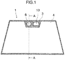
- FIG. 1 is a schematic plane view of an embodiment of a vehicular exterior member according to the present invention.
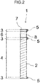
- FIG. 2 is a cross-sectional view along line A-A in FIG. 1 .
- the vehicular exterior member according to the embodiment is a window member applied to a front windshield of a vehicle, and particularly a window member attached to a vehicle equipped with a far-infrared camera.
- the embodiment of the vehicular exterior member of the present invention is not limited to the window member applied to the front windshield of a vehicle.
- the window member may be applied to a rear windshield or a side windshield.
- the vehicular exterior member may be applied to an exterior member for other than the window member, for example may be applied to an exterior member or a pillar.
- a glass base body 2 included in a window member 1 in the embodiment may be a single plate glass or a laminated glass.
- the glass base body 2 may be subjected to strengthening processing such as physical strengthening and chemical strengthening.
- the window member 1 in the embodiment includes a light blocking region 3.
- the window member 1 generally includes a light transmitting region 4 at its central portion for ensuring the driver's viewing field and the light blocking region 3 surrounding the light transmitting region 4.
- the far-infrared camera and other sensors being generally attached to the upper portion of the window member 1, the light blocking region 3 is also provided around the region where these sensors are attached. It is preferable that the light blocking region 3 be provided in such a manner as described above because the various sensors are protected from sunlight.
- the light blocking region 3 provided in such a manner as described above is also preferable from a design point of view because the light blocking region 3 causes wiring of the various sensors not to be seen from the outside of the vehicle.
- the light blocking region 3 is formed by providing a light blocking layer 5 on the glass base body 2 constituting the window member 1.
- the light blocking region 3 corresponds to the region in which the light blocking layer 5 is provided on the glass base body 2 in a plan view of the window member 1.
- a ceramic light blocking layer or a light blocking film can be used for the light blocking layer 5, for example.
- a ceramic layer can be used that includes a known material, such as a black ceramic layer.
- a light blocking polyethylene terephthalate (PET) film, a light blocking polyethylene naphthalate (PEN) film, and a light blocking polymethylmethacrylate (PMMA) film can be used, for example.
- the light blocking layer 5 may be formed between two glasses forming the laminated glass.
- the window member 1 in the embodiment includes a far-infrared ray transmitting region 6 in the light blocking region 3.
- the far-infrared ray transmitting region 6 has an opening 7 formed in the light blocking region 3 and a far-infrared ray transmitting member 8 disposed in the opening 7.
- the average transmittance of the far-infrared rays having a wavelength ranging from 8 to 13 ⁇ m of the far-infrared ray transmitting member 8 in the embodiment is equal to or larger than 25%, preferably equal to or larger than 40%, more preferably equal to or larger than 50%, furthermore preferably equal to or larger than 70%, and particularly preferably equal to or larger than 85%. It is essential for increasing the average transmittance of far-infrared rays 85% or more to provide an antireflection film.
- the material of the far-infrared ray transmitting member is not limited to a specific one as long as the transmittance described above is satisfied.
- Examples of the material include ZnS, Ge, Si, and chalcogenide glass.
- a preferable composition, which is expressed as an atomic percentage, of the chalcogenide glass is as follows:
- the method of attaching the far-infrared ray transmitting member 8 to the opening 7 is not limited to a specific one.
- both can be attached to each other with an adhesive such as a urethane-based adhesive and/or an acrylic adhesive.
- an adhesive such as a urethane-based adhesive and/or an acrylic adhesive.
- a difference in thermal expansion between the windowpane of the vehicle and the far-infrared ray transmitting member is large. It is thus preferable to select an adhesive that can lessen the difference, and is excellent in adhesive strength, impact resistance, and environmental resistance.
- the adhesion surface on the vehicle exterior side may be covered with a resin, for example, to enhance the environmental resistance.
- a gap of 0.2 to 1.5 mm is preferably provided between the far-infrared ray transmitting member 8 and the opening 7.
- the gap is smaller than 0.2 mm, the thermal expansion difference between the windowpane of the vehicle and the far-infrared ray transmitting member may cause the windowpane to be optically distorted or the windowpane and/or the far-infrared ray transmitting member to be damaged.
- the gap is more preferably equal to or larger than 0.3 mm, and furthermore preferably equal to or larger than 0.5 mm.
- the adhesive strength and the impact resistance may be lessened.
- the gap is more preferably equal to or smaller than 1.2 mm, and furthermore preferably equal to or smaller than 1.0 mm.
- the surface on the vehicle exterior side of the far-infrared ray transmitting member 8 is preferably formed flush with the surface on the vehicle exterior side of the light blocking region 3.
- the surface on the vehicle exterior side of the far-infrared ray transmitting member 8 is not formed flush with the surface on the vehicle exterior side of the light blocking region 3, and the vehicular exterior member 100 is applied to the front windshield of the vehicle, for example, a wiping effect of the wipers may be lessened. Even when the vehicular exterior member 100 is applied to ones other than the front windshield, a design property of the vehicle may be reduced due to a step, and dust may be accumulated on the step, for example.
- the far-infrared ray transmitting member is preferably formed corresponding to a curved shape of the vehicular exterior member to which the far-infrared ray transmitting member is applied.
- the method of forming the far-infrared ray transmitting member is not limited to a specific one. Polishing or molding is selected in accordance with the curved surface shape and the material.
- the surface on the vehicle exterior side and/or the surface on the vehicle interior side of the far-infrared ray transmitting member 8 may be coated.
- the surface on the vehicle exterior side or the vehicle interior side, or both sides, i.e., at least one of the surfaces on the vehicle exterior side and the surface on the vehicle interior side may be provided with an antireflection film.
- the antireflection film is preferably including one to twelve layers. The material is not limited to a specific one.
- the material include Ge, Si, ZnS, ZnSe, AS 2 S 3 , As 2 Se 3 , metal oxides (Al 2 O 3 , Bi 2 O 3 , CeO 2 , CuO, HfO 2 , MgO, SiO, SiO 2 , TiO, TiO 2 , Ti 2 O 3 , Y 2 O 3 , and ZrO 2 ), hydrogenated carbon, diamond-like carbon (DLC), and metal fluorides (MgF 2 , CaF 2 , SrF 2 , BaF 2 , PbF 2 , LaF 3 , and YF 3 ).
- metal oxides Al 2 O 3 , Bi 2 O 3 , CeO 2 , CuO, HfO 2 , MgO, SiO, SiO 2 , TiO, TiO 2 , Ti 2 O 3 , Y 2 O 3 , and ZrO 2
- hydrogenated carbon diamond-like carbon (DLC)
- DLC diamond-like carbon
- metal fluorides M
- the layer on the most vehicle exterior side is preferably a film that has a Mohs hardness of 7 or more and a high far-infrared ray transmittance from the viewpoint of scratch resistance.
- the layer on the most vehicle exterior side is particularly preferable a diamond-like carbon film.
- the shape of the far-infrared ray transmitting member 8 is not limited to a specific one.
- the shape is preferably a plate-like shape corresponding to the shape of the opening 7.
- the far-infrared ray transmitting member 8 preferably has a disk (columnar) shape.
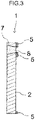
- the area of the opening 7 on the surface on the vehicle interior side is smaller than the area of the opening 7 on the surface on the vehicle exterior side.
- the area of the far-infrared ray transmitting member 8 on the surface on the vehicle interior side is preferably smaller than that on the surface on the vehicle exterior side in relation to the shape thereof. This structure increases the strength against the impact from the vehicle exterior side. As illustrated in FIG.
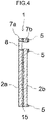
- the glass base body of the window member in the embodiment is a laminated glass including a first glass 2a (on the vehicle exterior side) and a second glass 2b (on the vehicle interior side)
- the area of an opening 7a of the first glass 2a is set to be larger than the area of an opening 7b of the second glass 2b
- the far-infrared ray transmitting member 8 having a size fitted to the size of the opening 7a of the first glass 2a is disposed in the opening 7a of the first glass 2a.
- the thickness of the far-infrared ray transmitting member 8 is equal to or larger than 1.5 mm, preferably equal to or larger than 2.0 mm, and more preferably equal to or larger than 3.0 mm from the viewpoint of strength.
- the thickness of the far-infrared ray transmitting member 8 is not limited to a specific one as long as the average transmittance of the far-infrared rays having a wavelength ranging from 8 to 13 ⁇ m is secured.
- the thickness is typically equal to or smaller than 5.0 mm.
- the far-infrared ray transmitting member may have a lens shape to achieve both widening a viewing angle of the far-infrared camera and improving mechanical characteristics thereof, for example.
- a structure is preferable because far-infrared rays can be efficiently converged even when the area of the far-infrared ray transmitting member is small.
- the number of far-infrared ray transmitting members having a lens shape is preferably one to three. Typically, two is preferable.
- the far-infrared ray transmitting member having a lens shape be preliminarily aligned and modularized, and be integrated with a housing or a bracket that adhesively bonds the far-infrared camera to the vehicular exterior member.
- the length of the longest straight line, in the straight lines connecting any desired two points on the surface on the vehicle exterior side of the far-infrared ray transmitting member 8 in the embodiment, is equal to or smaller than 80 mm, preferably equal to or smaller than 70 mm, and more preferably equal to or smaller than 65 mm.
- the shape of the surface on the vehicle exterior side of the far-infrared ray transmitting member 8 is circle, the length is the diameter of the circle.
- a radiation amount of far-infrared rays reaching the far-infrared camera attached to the window member 1 in the embodiment depends on the size of a largest circle, the largest circle is largest in circles formed inside a projected shape obtained by projecting the far-infrared ray transmitting member 8 in an optical axis of the far-infrared camera.
- FIG. 5 is an enlarged cross-sectional view of a portion around the far-infrared ray transmitting region 6 in the window member 1.
- the window member 1 is generally attached to the vehicle in such a manner as to be tilted at a certain angle ⁇ with respect to a horizontal direction H.
- a far-infrared camera 9 is generally attached such that an optical axis X is almost horizontal.
- the radiation amount of far-infrared rays reaching the far-infrared camera 9 depends on not only the size of the far-infrared ray transmitting member 8 but also the tilt angle ⁇ .
- the projected shape 11 is obtained by projecting, in the optical axis X of the far-infrared camera 9, the far-infrared ray transmitting member 8 on a projection surface 10 perpendicular to the optical axis X when the radiation amount of far-infrared rays reaching the far-infrared camera 9 is examined.
- the viewing field of the far-infrared camera 9 generally has a circular shape. It is thus appropriate to examine the size of a circle 12 that is the largest in circles formed inside the projected shape 11.
- FIG. 6 is a schematic view explaining the projected shape 11 projected on the projection surface 10 in FIG. 5 , and the circle 12 that is the largest circle in the circles formed inside the projected shape 11.
- the inventors had repeated experiments and found that, when the diameter of the circle 12, which is the largest circle in the circles formed inside the projected shape 11, is smaller than 12 mm, the radiation amount of far-infrared rays reaching the far-infrared camera 9 is reduced, causing the occurrence of luminance reduction and a blur in the obtained thermal image, thereby making it difficult to sufficiently ensure sharpness of the thermal image.
- the diameter of the circle 12, which is the largest circle in the circles formed inside the projected shape 11 obtained by projecting the far-infrared ray transmitting member 8 in the optical axis direction X of the far-infrared camera 9, is equal to or larger than 12 mm, preferably equal to or larger than 20 mm, and more preferably equal to or larger than 30 mm.
- the projected shape 11 obtained by projecting the far-infrared ray transmitting member 8 in the optical axis X direction of the far-infrared camera 9 is the drawing obtained by projecting, in the optical axis X, the shape of the surface on the vehicle exterior side of the far-infrared ray transmitting member 8 on the plane perpendicular to the optical axis X.
- the following inconveniences occur when an angle ⁇ is too small that is the tilt of the window member 1 in the embodiment with respect to the horizontal line when the window member 1 is attached to the vehicle.
- a region where only the far-infrared ray transmitting member 8 is included i.e., a region where the glass base body and the light blocking layer are not included (a region Y in FIG. 7 )
- a region Y in FIG. 7 becomes small when the window member 1 is observed in a direction parallel to the optical axis X.
- the angle ⁇ at which the region Y will not become too small is thus selected as appropriate.
- the center of the opening 7a of the first glass 2a and the center of the opening 7b of the second glass 2b may be shifted as appropriate.
- This structure eliminates the need to make the openings 7a and 7b excessively large for securing the size of the region Y even when particularly the angle ⁇ is small, thereby achieving particularly both high strength and high sharpness.
- the window member 1 in the embodiment preferably further includes, in the light blocking region 3, a visible light transmitting region 13 having a visible light transmittance equal to or larger than 70%. Provision of the visible light transmitting region 13 allows attaching of a visible light camera that images the outside through the visible light transmitting region 13.
- the attaching of the visible light camera in addition to the far-infrared camera makes it possible to combine pieces of information obtained by the two cameras and recognize information about the outside of the vehicle, thereby helping with increasing accuracy of object recognition.
- the far-infrared ray transmitting region 6 and the visible light transmitting region 13 are arranged in the light blocking region 3, the far-infrared camera and the visible light camera can be attached close to each other, which reduces a load in arithmetic processing of pieces of data obtained from each camera, and allows preferable routing of a power source and signal cables.
- the visible light transmitting region 13 is a region where the light blocking layer 5 is not provided in part of the light blocking region 3.
- the window member 1 in the embodiment may further include a LiDAR sensor and a millimeter wave radar besides the visible light camera.
- FIG. 9 is a schematic cross-sectional view of an embodiment of the far-infrared camera equipped vehicular exterior member of the present invention.
- This far-infrared camera equipped vehicular exterior member 100 according to the embodiment is a far-infrared camera equipped window member, in which the far-infrared camera 9 is attached to the window member 1 applied to the front windshield of the vehicle.
- the vehicular exterior member in the embodiment is not limited to the window member applied to the front windshield of the vehicle, likewise as described above.
- the far-infrared camera equipped window member 100 in the embodiment includes the window member 1 and the far-infrared camera 9.
- the window member 1 is already described.
- the far-infrared camera 9 is attached to the window member 1 in such a manner as to be capable of imaging external thermal images through the far-infrared ray transmitting region of the window member 1.
- the type of the far-infrared camera 9 is not limited to a specific type, and known far-infrared cameras can be used.
- the far-infrared camera 9 is attached to the window member 1 with a bracket 14, for example.
- the far-infrared camera 9 is generally attached such that the optical axis X is substantially horizontal.
- the temperature of the far-infrared camera 9 is preferably kept constant.
- One of the methods of keeping the temperature of the far-infrared camera 9 constant is to achieve high heat insulating property inside the bracket 14.
- the inside of the bracket 14 may be kept vacuum or the inside of the bracket 14 may be filled with a heat insulator. It is preferable for the far-infrared camera equipped window member 100 in the embodiment that the far-infrared camera 9 be attached to the window member 1 via through bracket 14 and the inside of the bracket 14 be kept vacuum or filled with a heat insulator.
- Another method of keeping the temperature of the far-infrared camera 9 constant is to adjust the temperature inside the bracket 14 by a temperature controller. It is preferable for the far-infrared camera equipped window member 100 in the present embodiment to include the far-infrared camera 9 that is attached to the window member through the bracket 14 and further include a temperature controller to adjust the temperature inside the bracket 14.
- the far-infrared camera equipped window member 100 in the present embodiment to further include the visible light camera that is attached to the window member 1 so as to be able to image external images through the visible light transmitting region 13.
- the optical axis of the far-infrared camera and the optical axis of the visible light camera be substantially in parallel, and the distance between the optical axes be equal to or smaller than 20 cm.
- the term substantially in parallel includes not only a case where those optical axes are completely in parallel but also a case where those optical axes are slightly out of parallel within a degree of an error. Being substantially in parallel allows the optical axis of the far-infrared camera and the center of the viewing field of the visible light camera to substantially coincide, and is preferable for information processing with images obtained from those cameras being combined.
- the visible light camera may be a stereo camera including a first camera and a second camera.
- the far-infrared camera is preferably disposed between the first and the second cameras. It is also preferable that the optical axes of the far-infrared camera and the first and second cameras be substantially in parallel, and the distance between the optical axes of any two of the three cameras be equal to or smaller than 20 cm.
- the LiDAR sensor and a millimeter wave radar may be further included beside the visible light camera, for example.
- those sensors are preferably arranged adjacent to one another while signal interference is prevented.
- Cylindrical far-infrared ray transmitting members (far-infrared ray transmitting members A to Q), each of which includes any one of Si, Ge, ZnS, and chalcogenide glass, and shaped in a column with a different size, were prepared.
- the material, a diameter L, and a thickness t of each of the far-infrared ray transmitting members are illustrated in Tables 1 to 3.
- the far-infrared ray transmitting member J was made as follows. A glass raw material was mixed to have a composition expressed as an atomic percentage as follows: Ga is 6.0%, Sb is 24.0%, Sn is 4.0%, S is 62.0%, Cs is 2.0%, and Cl is 2.0%. The mixed material was sealed in a quartz glass tube having an inner diameter of 25 mm, and then heated to 750°C and melted for four hours. The melted glass was rapidly cooled and then slowly cooled. The resulting ingot was cut together with the quartz glass tube and polished. As a result, the far-infrared ray transmitting member J was obtained.
- a five-layer antireflection film including Ge, Si, and YF 3 was formed on the surface on the vehicle exterior side of the far-infrared ray transmitting member O by a vapor deposition method.
- a two-layer antireflection film including DLC and Si was formed on the surface on the vehicle exterior side of the far-infrared ray transmitting member P, and a five-layer antireflection film including ZnS and Ge was formed on the surface on the vehicle interior side of the far-infrared ray transmitting member P by the vapor deposition method.
- a single layer of antireflection film including DLC was formed on the surface on the vehicle exterior side of the far-infrared ray transmitting member Q and a two-layer antireflection film including ZnS and Ge was formed on the surface on the vehicle interior side of the far-infrared ray transmitting member Q by the vapor deposition method.
- FIG. 10 illustrates the infrared ray transmission spectra of the far-infrared ray transmitting members B, D, F, H, I, and J.
- a laminated glass was prepared that included two soda lime glass sheets each having a size of 300 mm square and a thickness of 2.0 mm, and PVB having a thickness of 0.76 mm interposed between the two glass sheets.
- a through hole having a diameter of 14 mm was formed at the position apart from the center of the laminated glass by 100 mm in the direction toward the side of the glass sheet, the position serving as the center of the through hole.
- the far-infrared ray transmitting member A was attached to the through hole in such a manner as to be flush with the surface on the outside of the glass sheet with a urethane-based adhesive.
- the window member in example 1 was obtained.
- the urethane-based adhesive was dried for 5 days at ordinary temperature to be hardened.
- the window members in examples 2 and 3 were obtained in the same manner as example 1 except for that the diameter of the through hole was 26.5 mm and the far-infrared ray transmitting member B and C were attached respectively.
- the window member in example 4 was obtained in the same manner as example 3 except for that an acrylic adhesive was used.
- the acrylic adhesive was dried at 120°C for 1 hour, and was dried at ordinary temperature for 5 days to be hardened.
- the window members in examples 5 to 8 were obtained in the same manner as example 2 except for that the far-infrared ray transmitting members D to G were attached respectively.
- the window member in example 9 was obtained in the same manner as example 8 except for that an acrylic adhesive was used.
- the acrylic adhesive was dried at 120°C for 1 hour, and was dried at ordinary temperature for 5 days to be hardened.
- the window members in examples 10 to 13 were obtained in the same manner as example 2 except for that the far-infrared ray transmitting members H to K were attached respectively.
- the window members in examples 14 and 15 were obtained in the same manner as example 1 except for that the diameter of the through hole was 51.5 mm and the far-infrared ray transmitting members L and M were attached respectively.
- the window member in example 16 was obtained in the same manner as example 1 except for that the diameter of the through hole was 91.5 mm and the far-infrared ray transmitting member N was attached.
- the window members in examples 17 to 19 were obtained in the same manner as example 1 except for that the diameter of the through hole was 51.5 mm and the far-infrared ray transmitting members O, P, and Q were attached respectively.
- Ball drop strength evaluations 1 and 2 described below were done using the window members in examples 1 to 19. The window material that was passed in both tests was evaluated as "passed” while the window material that was failed in either one of the tests was evaluated as "failed”. The evaluation results are illustrated in Tables 1 and 2. (Ball drop strength evaluation 1)
- the evaluation was done using a ball drop device and a supporting frame in compliance with the impact resistance test in JIS R3211 and 3212-2015.
- the window member was kept in a room under conditions of a temperature of 23°C and a relative humidity of 50% for 4 hours, and then was fixed by the supporting frame such that the surface outside the window member faces upward.
- a steel ball of 226 g was dropped onto the center of the window member from a height of 10 m. When the steel ball did not pass through the window member and the total weight of peeled off fragments from the side opposite the impacted surface was equal to or smaller than 15 g, the window member was determined to be accepted. (Ball drop strength evaluation 2)
- the test was done in the same manner as the ball drop evaluation 1 except for that a steel ball of 509 g was used.
- a steel ball of 509 g was used.
- the window member was disposed in such a manner as to make an angle of ⁇ with respect to the horizontal surface.
- a far-infrared ray camera was disposed such that the optical axis was horizontal and coincided with the center of the far-infrared ray transmitting member, and the housing thereof was in contact with the window member.
- the far-infrared camera was Cube 417 manufactured by Wuhan Guide Infrared Co. Ltd. (resolution: 400 ⁇ 300, horizontal angle of view: 20°, vertical angle of view: 15°, and focal distance: 19 mm).
- the pedestrian located 100 m from the window was imaged by the far-infrared camera at an external temperature of 26°C.
- An image of 20 ⁇ 30 pixels was cut from the taken thermal image while the pedestrian was located at the center of the image.
- Each cut image was evaluated by a thermal image contrast as a ratio of "the maximum luminance/the minimum luminance" by image analysis. As larger the value of the thermal image contrast is, the sharper the taken image is. When the value of the thermal image contrast is equal to or larger than 3.0, the pedestrian located 100 m from the window is sufficiently recognizable.
- Tables 1 and 2 illustrate the values of ⁇ , the values of the diameter R of the largest circle in the circles formed inside the projected shape obtained by projecting the far-infrared ray transmitting member in the optical axis direction, and the values of the thermal image contrast.
- Example 1 Example 2
- Example 3 Example 4
- Example 5 Example 6
- Example 7 Structure of far-infrared transmitting member Far-infrared ray transmitting member A B C C D
- E F Material Si Si Si Si Si Si Ge L [mm] 12.5 25 25 25 25 25 25 25 25 t [mm] 2 1 2 2 3 5 1 Average transmittance [%] 39 47 39 39 33 14 48
- Example 8 Example 9
- the strength was insufficient in example 2, 7, and 14, which used the far-infrared ray transmitting members B, F, and L, each having the thickness t of 1 mm, respectively.
- the strength was insufficient in example 16, which used the far-infrared ray transmitting member N having the diameter L of 90 mm and the thickness t of 3 mm.
- the thermal image contrast was sufficient.
- the thermal image contrast was insufficient in the test in example 6 where the far-infrared ray transmitting member E was used.
- the average transmittance of far-infrared rays having a wavelength ranging from 8 to 13 ⁇ m of the far-infrared ray transmitting member E was 14%.
- the thermal image contrast was sufficient in the tests in examples 2, 3, 5, 7, 8, and from10 to 19, in each of which R was 12 mm or more, and the average transmittance of far-infrared rays having a wavelength ranging from 8 to 13 ⁇ m of the far-infrared ray transmitting member was 25% or more.
- the far-infrared ray transmitting member had both high strength and sufficient thermal image contrast when the far-infrared ray transmitting member satisfied the following conditions.
- the thickness t was equal to or larger than 1.5 mm
- the diameter L was equal to or smaller than 80 mm
- the average transmittance of far-infrared rays having a wavelength ranging from 8 to 13 ⁇ m was equal to or larger than 25%
- the diameter R of the largest circle in the circles formed inside the projected shape obtained by projecting the far-infrared ray transmitting member in the optical axis direction was equal to or larger than 12 mm.
Landscapes
- Chemical & Material Sciences (AREA)
- Engineering & Computer Science (AREA)
- Materials Engineering (AREA)
- Life Sciences & Earth Sciences (AREA)
- Chemical Kinetics & Catalysis (AREA)
- General Chemical & Material Sciences (AREA)
- Geochemistry & Mineralogy (AREA)
- Organic Chemistry (AREA)
- Multimedia (AREA)
- Signal Processing (AREA)
- Mechanical Engineering (AREA)
- Studio Devices (AREA)
- Fittings On The Vehicle Exterior For Carrying Loads, And Devices For Holding Or Mounting Articles (AREA)
- Photometry And Measurement Of Optical Pulse Characteristics (AREA)
- Laminated Bodies (AREA)
Applications Claiming Priority (2)
| Application Number | Priority Date | Filing Date | Title |
|---|---|---|---|
| JP2019136326 | 2019-07-24 | ||
| PCT/JP2020/024384 WO2021014857A1 (fr) | 2019-07-24 | 2020-06-22 | Élément extérieur de véhicule et élément extérieur pour véhicule équipé d'une caméra infrarouge lointain |
Publications (3)
| Publication Number | Publication Date |
|---|---|
| EP3988511A1 true EP3988511A1 (fr) | 2022-04-27 |
| EP3988511A4 EP3988511A4 (fr) | 2023-07-26 |
| EP3988511B1 EP3988511B1 (fr) | 2026-04-15 |
Family
ID=74193039
Family Applications (1)
| Application Number | Title | Priority Date | Filing Date |
|---|---|---|---|
| EP20843792.1A Active EP3988511B1 (fr) | 2019-07-24 | 2020-06-22 | Élément extérieur de véhicule et élément extérieur pour véhicule équipé d'une caméra infrarouge lointain |
Country Status (5)
| Country | Link |
|---|---|
| US (2) | US12035056B2 (fr) |
| EP (1) | EP3988511B1 (fr) |
| JP (2) | JP7597029B2 (fr) |
| CN (1) | CN114126924B (fr) |
| WO (1) | WO2021014857A1 (fr) |
Cited By (1)
| Publication number | Priority date | Publication date | Assignee | Title |
|---|---|---|---|---|
| EP4275961A4 (fr) * | 2021-01-08 | 2024-12-11 | Agc Inc. | Vitre de véhicule et procédé de fabrication de vitre de véhicule |
Families Citing this family (7)
| Publication number | Priority date | Publication date | Assignee | Title |
|---|---|---|---|---|
| EP4245611A4 (fr) * | 2020-11-10 | 2024-08-28 | Agc Inc. | Élément en résine pour véhicule, élément de fenêtre de véhicule et véhicule |
| WO2023062169A1 (fr) * | 2021-10-14 | 2023-04-20 | Agc Glass Europe | Vitrage doté d'un insert |
| JPWO2023171313A1 (fr) * | 2022-03-07 | 2023-09-14 | ||
| JPWO2023195524A1 (fr) * | 2022-04-08 | 2023-10-12 | ||
| CN118683296A (zh) * | 2023-03-24 | 2024-09-24 | 本田技研工业株式会社 | 车辆 |
| US12418712B2 (en) | 2023-11-14 | 2025-09-16 | Honda Motor Co., Ltd. | Camera assembly for vehicle and vehicle including same |
| US20250305885A1 (en) * | 2024-03-29 | 2025-10-02 | Lynred | Infrared camera and outer window assembly for a vehicle glazing |
Family Cites Families (18)
| Publication number | Priority date | Publication date | Assignee | Title |
|---|---|---|---|---|
| GB2271139A (en) * | 1992-10-03 | 1994-04-06 | Pilkington Plc | Vehicle window with insert of high infra-red transmittance |
| WO2002005013A2 (fr) | 2000-07-10 | 2002-01-17 | Ophir Optronics Ltd. | Procede et systeme d'assistance a la visibilite reduite |
| US20070216768A1 (en) * | 2006-03-14 | 2007-09-20 | Ford Global Technologies, Llc | Device and method for outwardly looking ir camera mounted inside vehicles particularly suited for pre-crash sensing and pedestrian detection |
| JP5194501B2 (ja) * | 2007-03-16 | 2013-05-08 | 株式会社豊田中央研究所 | 撮像素子、障害物検出装置及び方法 |
| JP2012189971A (ja) * | 2010-04-12 | 2012-10-04 | Fujifilm Corp | 投写用ズームレンズ、投写用変倍光学系および投写型表示装置 |
| US8544933B1 (en) * | 2012-09-21 | 2013-10-01 | Gary M. Fuller | Vehicle sun visor system |
| US20160284075A1 (en) * | 2013-03-14 | 2016-09-29 | Essess, Inc. | Methods, apparatus, and systems for structural analysis using thermal imaging |
| JP2014180898A (ja) * | 2013-03-18 | 2014-09-29 | Iss Kk | 赤外線カメラ一体化型フェンダーミラー及び赤外線カメラ一体化型フェンダーミラーの較正方法 |
| US20160259102A1 (en) * | 2013-12-18 | 2016-09-08 | Konica Minolta, Inc. | Light-reflecting film and light reflector using the same |
| PL3118036T3 (pl) * | 2014-03-14 | 2020-06-01 | Nippon Sheet Glass Company, Limited | Przednia szyba |
| JP6508448B2 (ja) * | 2014-03-17 | 2019-05-08 | 株式会社リコー | 検出器、センシング装置及び制御システム |
| JP6065296B2 (ja) * | 2014-05-20 | 2017-01-25 | パナソニックIpマネジメント株式会社 | 画像表示システム、および画像表示システムに用いられるディスプレイ |
| JP6717930B2 (ja) * | 2016-03-28 | 2020-07-08 | 富士フイルム株式会社 | 遠赤外線透過性組成物、形成体、積層体、遠赤外線透過フィルタ、固体撮像素子および赤外線カメラ |
| FR3057499B1 (fr) * | 2016-10-17 | 2018-11-16 | Saint-Gobain Glass France | Pare-brise d'aide a la conduite |
| JP2018119856A (ja) * | 2017-01-25 | 2018-08-02 | 京セラ株式会社 | 撮像部材および撮像装置 |
| US20210122671A1 (en) * | 2017-07-31 | 2021-04-29 | Corning Incorporated | Hard anti-reflective coatings |
| JP7049130B2 (ja) | 2018-02-13 | 2022-04-06 | ホーチキ株式会社 | 流水検知装置 |
| EP3767385A4 (fr) * | 2018-03-16 | 2021-11-03 | Nitto Denko Corporation | Élément de commande de lumière par gaz chromique |
-
2020
- 2020-06-22 CN CN202080052029.8A patent/CN114126924B/zh active Active
- 2020-06-22 JP JP2021533875A patent/JP7597029B2/ja active Active
- 2020-06-22 WO PCT/JP2020/024384 patent/WO2021014857A1/fr not_active Ceased
- 2020-06-22 EP EP20843792.1A patent/EP3988511B1/fr active Active
-
2022
- 2022-01-06 US US17/647,193 patent/US12035056B2/en active Active
-
2024
- 2024-05-31 US US18/679,776 patent/US12452549B2/en active Active
- 2024-11-25 JP JP2024204581A patent/JP7838618B2/ja active Active
Cited By (2)
| Publication number | Priority date | Publication date | Assignee | Title |
|---|---|---|---|---|
| EP4275961A4 (fr) * | 2021-01-08 | 2024-12-11 | Agc Inc. | Vitre de véhicule et procédé de fabrication de vitre de véhicule |
| US12549833B2 (en) | 2021-01-08 | 2026-02-10 | AGC Inc. | Vehicle glass and vehicle glass manufacturing method |
Also Published As
| Publication number | Publication date |
|---|---|
| US20240323550A1 (en) | 2024-09-26 |
| US12035056B2 (en) | 2024-07-09 |
| CN114126924B (zh) | 2024-04-19 |
| CN114126924A (zh) | 2022-03-01 |
| JP2025024218A (ja) | 2025-02-19 |
| US12452549B2 (en) | 2025-10-21 |
| JP7597029B2 (ja) | 2024-12-10 |
| EP3988511B1 (fr) | 2026-04-15 |
| US20220132047A1 (en) | 2022-04-28 |
| JPWO2021014857A1 (fr) | 2021-01-28 |
| JP7838618B2 (ja) | 2026-04-01 |
| EP3988511A4 (fr) | 2023-07-26 |
| WO2021014857A1 (fr) | 2021-01-28 |
Similar Documents
| Publication | Publication Date | Title |
|---|---|---|
| EP3988511B1 (fr) | Élément extérieur de véhicule et élément extérieur pour véhicule équipé d'une caméra infrarouge lointain | |
| US12194927B2 (en) | Glass for vehicles and camera unit | |
| EP4119511B1 (fr) | Vitre de véhicule, élément de cadre et procédé de fabrication de vitre de véhicule | |
| US20230345092A1 (en) | Vehicle glass and vehicle glass manufacturing method | |
| EP4275932A1 (fr) | Verre pour véhicule | |
| EP2056151B1 (fr) | Appareil de lentille d'imagerie et de capture d'image | |
| EP1903369B1 (fr) | Lentille d'imagerie et système de caméra comprenant la même lentille | |
| US20220196843A1 (en) | Lidar assembly for automotive applications comprising an anti reflection unit | |
| WO2025146805A1 (fr) | Verre de véhicule | |
| WO2025146804A1 (fr) | Unité de transmission d'infrarouge lointain et verre de véhicule | |
| US20240302573A1 (en) | Ir transmissive pane | |
| US20250074312A1 (en) | Vehicle glass and camera unit |
Legal Events
| Date | Code | Title | Description |
|---|---|---|---|
| STAA | Information on the status of an ep patent application or granted ep patent |
Free format text: STATUS: THE INTERNATIONAL PUBLICATION HAS BEEN MADE |
|
| PUAI | Public reference made under article 153(3) epc to a published international application that has entered the european phase |
Free format text: ORIGINAL CODE: 0009012 |
|
| STAA | Information on the status of an ep patent application or granted ep patent |
Free format text: STATUS: REQUEST FOR EXAMINATION WAS MADE |
|
| 17P | Request for examination filed |
Effective date: 20220121 |
|
| AK | Designated contracting states |
Kind code of ref document: A1 Designated state(s): AL AT BE BG CH CY CZ DE DK EE ES FI FR GB GR HR HU IE IS IT LI LT LU LV MC MK MT NL NO PL PT RO RS SE SI SK SM TR |
|
| DAV | Request for validation of the european patent (deleted) | ||
| DAX | Request for extension of the european patent (deleted) | ||
| A4 | Supplementary search report drawn up and despatched |
Effective date: 20230622 |
|
| RIC1 | Information provided on ipc code assigned before grant |
Ipc: B60J 1/02 20060101ALI20230616BHEP Ipc: B60J 1/00 20060101ALI20230616BHEP Ipc: C03C 3/32 20060101AFI20230616BHEP |
|
| STAA | Information on the status of an ep patent application or granted ep patent |
Free format text: STATUS: EXAMINATION IS IN PROGRESS |
|
| 17Q | First examination report despatched |
Effective date: 20250228 |
|
| GRAP | Despatch of communication of intention to grant a patent |
Free format text: ORIGINAL CODE: EPIDOSNIGR1 |
|
| STAA | Information on the status of an ep patent application or granted ep patent |
Free format text: STATUS: GRANT OF PATENT IS INTENDED |
|
| INTG | Intention to grant announced |
Effective date: 20251201 |
|
| GRAS | Grant fee paid |
Free format text: ORIGINAL CODE: EPIDOSNIGR3 |
|
| GRAA | (expected) grant |
Free format text: ORIGINAL CODE: 0009210 |
|
| STAA | Information on the status of an ep patent application or granted ep patent |
Free format text: STATUS: THE PATENT HAS BEEN GRANTED |
|
| AK | Designated contracting states |
Kind code of ref document: B1 Designated state(s): AL AT BE BG CH CY CZ DE DK EE ES FI FR GB GR HR HU IE IS IT LI LT LU LV MC MK MT NL NO PL PT RO RS SE SI SK SM TR |
|
| REG | Reference to a national code |
Ref country code: CH Ref legal event code: F10 Free format text: ST27 STATUS EVENT CODE: U-0-0-F10-F00 (AS PROVIDED BY THE NATIONAL OFFICE) Effective date: 20260415 |