EP3988854A1 - Unité de verrouillage d'un dispositif d'aération - Google Patents
Unité de verrouillage d'un dispositif d'aération Download PDFInfo
- Publication number
- EP3988854A1 EP3988854A1 EP20203051.6A EP20203051A EP3988854A1 EP 3988854 A1 EP3988854 A1 EP 3988854A1 EP 20203051 A EP20203051 A EP 20203051A EP 3988854 A1 EP3988854 A1 EP 3988854A1
- Authority
- EP
- European Patent Office
- Prior art keywords
- duct
- air
- exhaust air
- heat exchangers
- closure unit
- Prior art date
- Legal status (The legal status is an assumption and is not a legal conclusion. Google has not performed a legal analysis and makes no representation as to the accuracy of the status listed.)
- Granted
Links
Images


Classifications
-
- F—MECHANICAL ENGINEERING; LIGHTING; HEATING; WEAPONS; BLASTING
- F24—HEATING; RANGES; VENTILATING
- F24F—AIR-CONDITIONING; AIR-HUMIDIFICATION; VENTILATION; USE OF AIR CURRENTS FOR SCREENING
- F24F13/00—Details common to, or for air-conditioning, air-humidification, ventilation or use of air currents for screening
- F24F13/08—Air-flow control members, e.g. louvres, grilles, flaps or guide plates
- F24F13/10—Air-flow control members, e.g. louvres, grilles, flaps or guide plates movable, e.g. dampers
- F24F13/14—Air-flow control members, e.g. louvres, grilles, flaps or guide plates movable, e.g. dampers built up of tilting members, e.g. louvre
- F24F13/1426—Air-flow control members, e.g. louvres, grilles, flaps or guide plates movable, e.g. dampers built up of tilting members, e.g. louvre characterised by actuating means
-
- F—MECHANICAL ENGINEERING; LIGHTING; HEATING; WEAPONS; BLASTING
- F24—HEATING; RANGES; VENTILATING
- F24F—AIR-CONDITIONING; AIR-HUMIDIFICATION; VENTILATION; USE OF AIR CURRENTS FOR SCREENING
- F24F12/00—Use of energy recovery systems in air conditioning, ventilation or screening
- F24F12/001—Use of energy recovery systems in air conditioning, ventilation or screening with heat-exchange between supplied and exhausted air
- F24F12/006—Use of energy recovery systems in air conditioning, ventilation or screening with heat-exchange between supplied and exhausted air using an air-to-air heat exchanger
-
- F—MECHANICAL ENGINEERING; LIGHTING; HEATING; WEAPONS; BLASTING
- F24—HEATING; RANGES; VENTILATING
- F24F—AIR-CONDITIONING; AIR-HUMIDIFICATION; VENTILATION; USE OF AIR CURRENTS FOR SCREENING
- F24F13/00—Details common to, or for air-conditioning, air-humidification, ventilation or use of air currents for screening
- F24F13/08—Air-flow control members, e.g. louvres, grilles, flaps or guide plates
- F24F13/10—Air-flow control members, e.g. louvres, grilles, flaps or guide plates movable, e.g. dampers
-
- F—MECHANICAL ENGINEERING; LIGHTING; HEATING; WEAPONS; BLASTING
- F24—HEATING; RANGES; VENTILATING
- F24F—AIR-CONDITIONING; AIR-HUMIDIFICATION; VENTILATION; USE OF AIR CURRENTS FOR SCREENING
- F24F12/00—Use of energy recovery systems in air conditioning, ventilation or screening
- F24F12/001—Use of energy recovery systems in air conditioning, ventilation or screening with heat-exchange between supplied and exhausted air
- F24F2012/007—Use of energy recovery systems in air conditioning, ventilation or screening with heat-exchange between supplied and exhausted air using a by-pass for bypassing the heat-exchanger
-
- Y—GENERAL TAGGING OF NEW TECHNOLOGICAL DEVELOPMENTS; GENERAL TAGGING OF CROSS-SECTIONAL TECHNOLOGIES SPANNING OVER SEVERAL SECTIONS OF THE IPC; TECHNICAL SUBJECTS COVERED BY FORMER USPC CROSS-REFERENCE ART COLLECTIONS [XRACs] AND DIGESTS
- Y02—TECHNOLOGIES OR APPLICATIONS FOR MITIGATION OR ADAPTATION AGAINST CLIMATE CHANGE
- Y02B—CLIMATE CHANGE MITIGATION TECHNOLOGIES RELATED TO BUILDINGS, e.g. HOUSING, HOUSE APPLIANCES OR RELATED END-USER APPLICATIONS
- Y02B30/00—Energy efficient heating, ventilation or air conditioning [HVAC]
- Y02B30/56—Heat recovery units
Definitions
- the present invention relates to a closure unit of a ventilation device, in particular a ventilation device with heat recovery, a ventilation device and a method for operating a ventilation device of a building.
- Buildings are increasingly equipped with ventilation systems with heat recovery.
- the outside air that is brought into the building from outside and the exhaust air that is brought outside from the inside of the building are guided through a common heat exchanger.
- heat is transferred from one air volume flow to the other.
- bypass ducts are provided in order to direct one of the two air volume flows inwards or outwards without passing through the heat exchanger.
- the passage through the heat exchanger is closed by a closure device.
- This closure device is usually a flap or a roller shutter.
- DE 10 2013 216 306 A1 uses a first damper in the bypass duct and a second damper in the supply air duct. The two flaps are operated separately from each other.
- EP 0 044 560 B1 discloses a ventilation device with a heat exchanger and a bypass, the device having individually actuated flaps.
- EP 1 132 690 B1 shows two heat exchangers connected in series, two bypass channels and several individually operated flaps.
- EP 2 498 014 B1 discloses a heat recovery module with a roller shutter which when rolled up blocks the bypass and unblocks the heat exchanger and when unrolled opens the bypass but blocks the heat exchanger.
- EP 1 962 031 A2 shows a heat recovery module with a flap and a slide that form a structural unit. Their adjustment movements are positively coupled, which is achieved by connecting the parts that are aligned perpendicular to one another. This structural unit is directly adjacent to the heat exchanger bypass device without any further lines or channels.
- Heat exchangers connected in parallel are also known.
- U.S. 2007/0158049 A1 discloses, for example, such a ventilation unit with a plurality of heat exchangers arranged next to one another, which are connected in parallel and are correspondingly flowed through in parallel.
- a common bypass duct is arranged next to the heat exchangers.
- DE 10 2011 114 885 A1 describes a heat exchanger arrangement with a gaseous and a liquid fluid.
- the arrangement has two parallel flow heat exchangers, which are arranged spatially offset one behind the other.
- Two bypass channels enable air to be supplied to and removed from the heat exchangers.
- Each bypass channel has its own, separately operated shutter.
- the known devices still require a relatively large amount of space.
- the use of several heat exchangers has the disadvantage that more bypass ducts and dampers are required, which increases space requirements and manufacturing costs, in particular because of the increased number of motors for actuating the dampers.
- the closure unit of a ventilation device has at least two pivotably arranged flaps for closing one ventilation duct each.
- the two flaps are moveable by means of a common shaft defining a common pivot axis.
- the two flaps are therefore positively coupled and can be operated simultaneously using a single motor.
- This locking unit is suitable for a wide variety of applications in ventilation devices in which two ventilation ducts have to be closed or opened at the same time. Depending on the position of the flaps, one ventilation duct can be opened and the other closed. However, both ventilation ducts are preferably closed or opened at the same time.
- This closure unit serves, for example, as a double bypass damper with a single motor.
- this closure unit is preferably used in a ventilation device which nevertheless has a bypass function without a separate bypass duct. This is explained in more detail later in the text.
- This closure unit is particularly suitable for use in ventilation devices with heat recovery, in particular by means of heat exchangers.
- heat exchangers There are preferably two or more heat exchangers, which are preferably operated in parallel. This is explained in more detail below in the text.
- the pivot axis of the closure unit according to the invention preferably runs centrally through the two flaps.
- the shaft can be operated manually. However, it is preferably driven by a motor.
- the motor is preferably arranged in the longitudinal direction of the shaft above or below the two flaps or in the middle between the two flaps. Since only a single motor needs to be used, manufacturing costs can be reduced.
- the arrangement above or below the flaps reduces the space requirement, in particular if a motor designed as flat as possible is used. This arrangement also allows optimal accessibility of the engine in a ventilation device, which greatly facilitates maintenance.
- the two flaps are preferably arranged at an angle of 90° to one another. If the two ventilation ducts run parallel to one another, with this 90° arrangement of the flaps, a first duct is closed by the first flap, while the second duct is opened by the second flap. If the ventilation ducts are arranged at an angle of 90° to one another, the ducts are closed or released together if the flaps are arranged at 90°. This 90° arrangement of the flaps thus enables use in differently arranged ducts. The same applies if the flaps are arranged parallel to one another, albeit with the opposite effect in their closing behavior.
- each of the two flaps forms a closure surface, with the two closure surfaces containing the pivot axis of the shaft. This arrangement facilitates inexpensive manufacture and requires relatively little space.
- the two flaps have a rectangular cross-section.
- the shape of the flap is preferably adapted to the shape of the channels to be closed.
- the closure unit has a first housing for pivotably receiving a first flap and a second housing for pivotably receiving a second flap.
- the shaft has an upper portion pivotally supported in the first housing and having a first end connected to the first door and a second end connected to the motor.
- the shaft also includes a lower portion having a first end connected to the first door and a second end connected to the second door. The second flap and/or the second end of the lower section of the shaft is pivoted in the second housing.
- the closure unit can be designed as a relatively simple and robust module that can be used as a structural unit in a ventilation device and, if necessary, can also be easily replaced as part of service work.
- This locking unit can be used in a wide variety of applications Use ventilation devices. However, it is preferably used in the ventilation device according to the invention described below.
- This ventilation device can be designed to be extremely compact and flat. The ventilation device nevertheless enables a large volume flow.
- a ventilation system of a building in particular in a central ventilation system of a building, preferably a residential or office building.
- the ventilation device according to the invention does not require an additional bypass channel.
- the two heat exchangers themselves form bypass channels, namely when only one of the two air volume flows flows through them and as a result no heat exchange can take place with the other air volume flow.
- the closure unit used in the ventilation device according to the invention can consist of two individually actuated or jointly actuated, in particular forcibly coupled, closure bodies.
- the closure unit according to the invention described above is preferably used.
- the closure unit is designed in such a way that it selectively only partially enables or prevents the air volume flows by only partially releasing or only partially closing the ducts or partial ducts.
- this arrangement thus makes it possible to guide the air volume flows with different parts through the two heat exchangers.
- the outside air can be routed 2/3 through the first heat exchanger and 1/3 through the second heat exchanger, in which case the exhaust air is routed 1/3 through the first heat exchanger and 2/3 through the second heat exchanger.
- the closure unit of the ventilation device according to the invention preferably has two closure bodies that can be actuated jointly by means of a common motor.
- the closure bodies can be flaps as in the device according to the invention. They can also be differently arranged flaps or other types of closure bodies.
- the channels are divided into sub-channels. That is, the outside air duct is divided into a first outside air sub-duct and a second outside air sub-duct, with the first outside air sub-duct leading into the first heat exchanger and the second outside air sub-duct leading into the second heat exchanger.
- the supply air duct is divided into a first supply air sub-duct and a second supply air sub-duct, with the first supply air sub-duct leading out of the first heat exchanger and the second supply air sub-duct leading out of the second heat exchanger.
- the exhaust air duct is divided into a first partial exhaust air duct and a second exhaust air partial duct, with the first exhaust air partial duct leading into the first heat exchanger and the second exhaust air partial duct leading into the second heat exchanger.
- the exhaust air duct is divided into a first exhaust air sub-duct and a second exhaust air sub-duct, with the first exhaust air sub-duct leading out of the first heat exchanger and the second exhaust air sub-duct leading out of the second heat exchanger.
- Those partial channels which are opened or closed by means of the closure unit preferably run offset from one another in the region of the closure unit at an angle of 90°.
- the flaps are preferably also arranged offset from one another at an angle of 90°, with one flap each being arranged in a partial channel.
- the partial channels all have the same cross-sectional area and preferably even the same cross-sectional shape.
- a first sub-channel has a smaller cross section than an associated second sub-channel, at least in the area of the closure device.
- the partial channel that is arranged upstream of the heat exchanger in the direction of flow is designed to be larger, so that the partial channel that follows after the heat exchanger in the direction of flow is smaller. This achieves an optimized flow behavior. The flow is improved and equal distribution in front of the heat exchanger and higher efficiency are obtained.
- the width of the partial channels is the same, but the height is different.
- At least one fan is preferably present. Preferably there are two fans; one for outside air or supply air and one for extract air or exhaust air.
- the closure unit simultaneously closes the first supply air sub-duct and the second exhaust air sub-duct or releases it, or the closure unit simultaneously closes the first outside air sub-duct and the second exhaust air sub-duct or releases it.
- the outside air duct feeds the outside air from the outside to the two heat exchangers
- the supply air duct leads the outside air from the heat exchangers into the interior of the building
- the exhaust air duct leads the exhaust air from the interior of the building to the two heat exchangers
- the exhaust air duct leads the exhaust air out of the heat exchanger to the outside.
- the shutter unit is optional all channels free or allows outside air flow through one of the two heat exchangers while preventing exhaust air flow through that one of the two heat exchangers while allowing exhaust air flow through the other of the two heat exchangers and preventing outside air flow through that other of the two heat exchangers .
- a simple closure unit for example with two flaps that can be actuated together and are preferably positively coupled, is sufficient to prevent heat exchange between the two air volume flows.
- figure 1 shows a schematic view of a ventilation device according to the invention for use in a ventilation system of a building, in particular in a central ventilation system.
- the ventilation device has a closed housing 7 which is designed as flat as possible.
- two heat exchangers 60, 61 are arranged in the housing 7 . They are preferably arranged side by side and operated in parallel.
- the heat exchangers 60, 61 are preferably plate heat exchangers of a known type or differently designed, as flat as possible heat exchangers of a known type.
- exhaust air The exhaust air discharged to the outside is called exhaust air
- supply air the outside air directed into the interior. If the two air volume flows of the outside air and the exhaust air flow through both heat exchangers 60, 61 simultaneously, heat transfer takes place in a known manner, which is used for heat recovery in winter and possibly also for cooling in summer. Depending on the time of year or temperature conditions, heat exchange is either not required or only required to a lesser extent.
- fans 80, 81 there is preferably at least one, preferably several fans 80, 81 present.
- the fans 80, 81 are preferably operated by means of a controller, preferably according to a program.
- a first and second outside air sub-duct 400, 401, a first and second supply air sub-duct 410, 411, a first and second exhaust air sub-duct 500, 501 and a first and second exhaust air sub-duct 510, 511 are present.
- the first sub-ducts 400, 410, 500, 510 are connected to the first heat exchanger 60 and the second sub-ducts 401, 411, 501, 511 to the second heat exchanger 61.
- closure unit M which closes two of the partial channels together.
- the closure unit M has two closure bodies, one of the closure bodies closing one of the two partial channels.
- the two closure bodies are flaps.
- the closure bodies are preferably motor-driven and can be actuated via a controller.
- the two closure bodies are arranged spatially separate from one another and are actuated simultaneously or one after the other by means of the control.
- the two closure bodies are arranged adjacent to one another.
- the two partial channels to be closed run in the area of the closure unit M, also called the closure module or module, and thus in the area of the closure body adjacent to one another, so that they can be closed and opened again together at the same time.
- the two partial channels can run parallel to one another. However, they preferably intersect, for which purpose they preferably run one above the other. In figure 1 this applies to the first supply air sub-duct 410 and the second exhaust air sub-duct 501. If these two sub-ducts are open, both the outside air volume flow and the exhaust air volume flow run through both heat exchangers 60, 61. The two heat exchangers 60, 61 are thus flowed through in parallel by the two air volume flows.
- the outside air volume flow can only flow through the second heat exchanger 61 and the exhaust air volume flow can only flow through the first heat exchanger 60 .
- the streams are thus "bypassed", i.e. guided past one another without a separate bypass channel having to be present for this purpose. There is no heat transfer between the two air volume flows.
- the closure unit can also be arranged on the other side of the heat exchangers 60, 61.
- the second outside air sub-duct 401 and the first exhaust air sub-duct 510 are arranged at an angle of 90° to one another and one above the other so that they can be closed together.
- the closure unit M can also close other combinations of first and second sub-ducts, as is easily recognizable for the person skilled in the art.
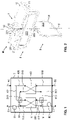
- a closure unit M according to the invention is shown, which can preferably be used in the described ventilation device according to the invention.
- this closure unit M can also be used in other ventilation devices in which two ducts arranged one above the other or next to one another are to be closed together and at the same time.
- the ducts cross at an angle of 90°. If they are arranged next to each other, they run parallel. In both cases, a pivot axis of the closure unit runs at an angle of 90° in relation to the longitudinal directions of the air ducts. In the case of air ducts arranged one above the other, the pivot axis runs vertically, in the case of air ducts arranged next to one another, it runs horizontally.
- the closure unit comprises a first motor unit 1, a first flap device 2 and a second flap device 3. It is preferably designed as a structural unit in the form of a module that can be installed as a whole in the ventilation device. In other embodiments, the parts are assembled individually or as sub-modules.
- the motor unit 1 has a motor 10 which is designed as flat as possible. It is held fixed on a frame 20 , 21 of the first flap device 2 . A power cable 11 leads to a control of the ventilation device, not shown.
- the motor unit 1 also has a turntable 12 which can be pivoted by means of the motor 10 . It can also be operated by hand. In this example, there is a component 13 with a magnet for this purpose
- the device has a multi-piece shaft 221, 222, 223 which defines a pivot axis S .
- An upper shaft portion 221 is held fixed in the turntable 12 and pivoted or rotated with this.
- the upper shaft section 221 is connected to a pivotable or rotatable first flap 220 of the first flap device 2 .
- a lower shaft portion 222 extends downwardly from the first door 220 along the pivot axis S .
- This section 222 is also preferably integrally formed on the first flap 220 . It is connected to a second flap 320 of the second flap device 3 . It is preferably detachably connected to this.
- the pivot axis S runs within the surfaces of the two flaps 220, 320. It preferably runs centrally.
- the two flaps 220, 320 are arranged at an angle of 90° to one another. They are designed according to the shape of the sub-channels receiving them.
- the partial air ducts have a rectangular cross section and the flaps 220, 320 are correspondingly rectangular. They can be the same size and have the same shape.
- the duct downstream of the heat exchanger in the direction of flow is narrower for flow reasons, so that the first flap 220 is narrower and longer than the second flap 320.
- flaps 220, 320 are rotated by means of the motor-driven shaft 221, 222, they pivot together, both of which open or close their sub-channels at the same time. Intermediate positions are also possible, in which case they open or close their sub-channels in the same ratio.
- the two flaps 220,320 are preferably held in frames 20,21,30,31.
- the unit M can be arranged as an intermediate piece between two sections of the partial air ducts and connected to it. This facilitates the assembly of the ventilation device, in particular if it is also designed as a structural unit, i.e. as a module.
- the first flap unit 2 comprises three components: a right-hand frame part 20, a left-hand frame part 21 and a first flap element 22 arranged in it so that it can pivot.
- the two frame parts 20, 21 each have a top surface 200, 210 and upstanding side walls 201, 211 with inwardly directed retaining lugs 202, 212 for receiving and fixing the engine 10 in place.
- the two frame parts 20, 21 each have a semicircular recess 206, 216 at the top and bottom, which form circular openings when the first flap unit 2 is assembled and which serve to accommodate the shaft sections 221, 222 and a second end part 322.
- the two frame parts 20, 21 can preferably be joined and fixed to form a common frame by means of snap connections.
- snap-in brackets 203, 213 and associated snap-in hooks 204, 214 there are, for example, snap-in brackets 203, 213 and associated snap-in hooks 204, 214.
- the side surfaces 205, 215 are preferably triangular in cross-section, tapering downwards, i.e. away from the engine 10.
- the first flap element 22 is preferably formed in one piece. It has the plate-shaped first flap 220 on which, in the middle at the top end, the upper Shaft section 221 and, centrally at the lower end, the lower shaft section 222 is formed.
- the lower shaft section 222 ends in a first end part 223 designed as a polygon.
- the first flap 220 and/or the first frame 20, 21 are preferably designed in such a way that they close as tightly as possible. It is rotatable or pivotable in the frame 20, 21 held.
- the upper shaft section 221 passes through the upper area of the frame 20, 21 and the lower shaft section 223 through the lower area. Both protrude from the frame 20, 21 so that they can be connected to the motor 10 or the turntable 12 and to the second flap unit 3.
- the second flap unit 3 also has a right and a left frame part 30, 31 with a second flap element 32 held between them.
- the two frame parts 30, 31 each have a rectangular frame 300, 310, the walls of which are relatively narrow. These two frames 300, 310 can preferably be connected and fixed by means of snap connections. Corresponding snap-in brackets 303, 313 and snap-in hooks 304, 314 are present.
- the frames 300, 310 have semicircular recesses 306, 316 arranged in the center at the top, which form a common circular passage opening for receiving a shaft bearing 321 when the frame 30, 31 is in the assembled state.
- the frames 300, 310 also have semi-circular recesses 306, 316 arranged centrally at the bottom, which form a common circular receiving opening for receiving a second end part 322 when the frame 30, 31 is in the assembled state.
- the second flap element 32 is preferably also formed in one piece. It has the plate-shaped second flap 320 on which the shaft bearing 321 is formed in the form of a polygonal socket in the middle at the upper end.
- the shaft bearing 321 is used for the non-rotatable connection to the first end part 223 of the lower shaft section 222.
- the second end part 322 is formed centrally at the lower end of the second flap 320, since the second flap 320 is rotatably or pivotably supported in the lower receiving opening 316 of the second frame 30, 31 is used.
- the second flap 320 and/or the second frame 30, 31 are also preferably designed in such a way that they close as tightly as possible. It can be rotated or swiveled in the second Frame 30, 31 held.
- the individual elements of the closure unit M are preferably made of metal or plastic. They are inexpensive to manufacture and easy to assemble. In addition, the installation in the ventilation device is simplified thanks to the two frames.
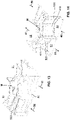
- FIGS. 13 and 14 show a section of a ventilation device with an integrated closure unit according to the invention.
- the sub-channels are provided with the same reference numbers as in the example described above.
- the supply air duct can also be the exhaust air duct and the outside air duct can also be the exhaust air duct.
- the text is to be understood accordingly. The same applies to the sub-channels.
- the closure unit according to the invention in which two flaps are actuated together, enables the use of two heat exchangers operated in parallel without an additional bypass channel.
- REFERENCE LIST 1 motor unit 304 snap hook 10 engine 306 recess 11 Cable 31 left frame part 12 turntable 310 left frame 13 Component with magnet 313 snap-in bracket 314 snap hook 2 first flap device 316 recess 20 right frame part 32 second flap element 200 right upper surface 320 second flap 201 Side wall 321 shaft bearing 202 restraint nose 322 second end part 203 snap-in bracket 204 snap hook 40 outdoor air duct 205 side face 400 first outdoor air duct 206 recess 401 second outdoor air duct 21 left frame part 41 supply air duct 210 upper left surface 410 first supply air duct 211 Side wall 411 second supply air duct 212 restraint nose 50 exhaust duct 213 snap-in bracket 500 first exhaust air duct 214 snap hook 501 second exhaust air duct 215 side face 51 exhaust air duct 216 recess 510 first exhaust air duct 22
Landscapes
- Engineering & Computer Science (AREA)
- Chemical & Material Sciences (AREA)
- Combustion & Propulsion (AREA)
- Mechanical Engineering (AREA)
- General Engineering & Computer Science (AREA)
- Air-Flow Control Members (AREA)
- Air-Conditioning For Vehicles (AREA)
Priority Applications (6)
| Application Number | Priority Date | Filing Date | Title |
|---|---|---|---|
| EP20203051.6A EP3988854B1 (fr) | 2020-10-21 | 2020-10-21 | Unité de verrouillage d'un dispositif d'aération |
| PCT/EP2021/078504 WO2022084156A1 (fr) | 2020-10-21 | 2021-10-14 | Unité de fermeture d'un dispositif de ventilation |
| EP21793913.1A EP4232758B1 (fr) | 2020-10-21 | 2021-10-14 | Dispositif d'aération |
| CN202180071908.XA CN116507856A (zh) | 2020-10-21 | 2021-10-14 | 通风设备的封闭单元 |
| US18/031,685 US20230383985A1 (en) | 2020-10-21 | 2021-10-14 | Closure unit for a ventilation device |
| CA3195822A CA3195822A1 (fr) | 2020-10-21 | 2021-10-14 | Unite de fermeture d'un dispositif de ventilation |
Applications Claiming Priority (1)
| Application Number | Priority Date | Filing Date | Title |
|---|---|---|---|
| EP20203051.6A EP3988854B1 (fr) | 2020-10-21 | 2020-10-21 | Unité de verrouillage d'un dispositif d'aération |
Publications (2)
| Publication Number | Publication Date |
|---|---|
| EP3988854A1 true EP3988854A1 (fr) | 2022-04-27 |
| EP3988854B1 EP3988854B1 (fr) | 2026-03-18 |
Family
ID=73005406
Family Applications (2)
| Application Number | Title | Priority Date | Filing Date |
|---|---|---|---|
| EP20203051.6A Active EP3988854B1 (fr) | 2020-10-21 | 2020-10-21 | Unité de verrouillage d'un dispositif d'aération |
| EP21793913.1A Active EP4232758B1 (fr) | 2020-10-21 | 2021-10-14 | Dispositif d'aération |
Family Applications After (1)
| Application Number | Title | Priority Date | Filing Date |
|---|---|---|---|
| EP21793913.1A Active EP4232758B1 (fr) | 2020-10-21 | 2021-10-14 | Dispositif d'aération |
Country Status (5)
| Country | Link |
|---|---|
| US (1) | US20230383985A1 (fr) |
| EP (2) | EP3988854B1 (fr) |
| CN (1) | CN116507856A (fr) |
| CA (1) | CA3195822A1 (fr) |
| WO (1) | WO2022084156A1 (fr) |
Families Citing this family (2)
| Publication number | Priority date | Publication date | Assignee | Title |
|---|---|---|---|---|
| DE102023200371A1 (de) * | 2023-01-18 | 2024-07-18 | Maico Elektroapparate-Fabrik Gesellschaft mit beschränkter Haftung | Lüftungseinrichtung für ein Gebäude sowie Verfahren zum Betreiben einer Lüftungseinrichtung |
| DE102024105964A1 (de) * | 2024-03-01 | 2025-09-04 | Viessmann Holding International GmbH | Lüftungsanlage |
Citations (11)
| Publication number | Priority date | Publication date | Assignee | Title |
|---|---|---|---|---|
| EP0044560B1 (fr) | 1980-07-22 | 1984-05-02 | Eltreva AG | Installation d'aérage pour des espaces ventilés en circulation forcée |
| WO1997006390A1 (fr) * | 1995-08-08 | 1997-02-20 | Turcotte Inc. | Unite combinee de renouvellement et de conditionnement de l'air |
| EP1132690B1 (fr) | 2000-03-09 | 2004-07-07 | KRANTZ-TKT GmbH | Dispositif permettant de tempérer et/ou de ventiler une pièce |
| US20070158049A1 (en) | 2005-08-16 | 2007-07-12 | Lg Electronics Inc. | Ventilation system |
| EP1962031A2 (fr) | 2007-02-21 | 2008-08-27 | Robert Bosch GmbH | Module de récupération de la chaleur |
| DE202012010671U1 (de) * | 2012-05-16 | 2012-12-17 | Ltg Aktiengesellschaft | Lufttechnisches Gerät zur Be- und Entlüftung |
| DE102011114885A1 (de) | 2011-10-05 | 2013-04-11 | Michael Kass | Wärmetauscheranordnung und Verfahren zum Betrieb |
| KR101263656B1 (ko) * | 2012-01-05 | 2013-05-22 | 대림산업 주식회사 | 열교환기의 병렬배치와 댐퍼부재의 전환을 통한 바이패스 기능을 가지는 열교환기 조립체 및 이를 이용한 실내외 공기의 급배기방법 |
| DE102013216306A1 (de) | 2013-08-16 | 2015-02-19 | Blumartin Gmbh | Raumkühlende Steuerung für Raumlüftungsvorrichtung mit Wärmerückgewinnung |
| EP2498014B1 (fr) | 2011-03-11 | 2015-05-27 | Vaillant GmbH | Module de récupération de la chaleur |
| EP3260793A1 (fr) * | 2016-06-22 | 2017-12-27 | LUNOS Lüftungstechnik GmbH für Raumluftsysteme | Appareil de ventilation à filtre amovible |
Family Cites Families (2)
| Publication number | Priority date | Publication date | Assignee | Title |
|---|---|---|---|---|
| CN204313446U (zh) * | 2014-12-13 | 2015-05-06 | 浙江科力鑫环境设备科技有限公司 | 方便操作的新风换气机 |
| CN109477657A (zh) * | 2016-03-31 | 2019-03-15 | 工业设计实验室股份有限公司 | 紧凑型热回收通风系统 |
-
2020
- 2020-10-21 EP EP20203051.6A patent/EP3988854B1/fr active Active
-
2021
- 2021-10-14 US US18/031,685 patent/US20230383985A1/en active Pending
- 2021-10-14 WO PCT/EP2021/078504 patent/WO2022084156A1/fr not_active Ceased
- 2021-10-14 CA CA3195822A patent/CA3195822A1/fr active Pending
- 2021-10-14 CN CN202180071908.XA patent/CN116507856A/zh active Pending
- 2021-10-14 EP EP21793913.1A patent/EP4232758B1/fr active Active
Patent Citations (11)
| Publication number | Priority date | Publication date | Assignee | Title |
|---|---|---|---|---|
| EP0044560B1 (fr) | 1980-07-22 | 1984-05-02 | Eltreva AG | Installation d'aérage pour des espaces ventilés en circulation forcée |
| WO1997006390A1 (fr) * | 1995-08-08 | 1997-02-20 | Turcotte Inc. | Unite combinee de renouvellement et de conditionnement de l'air |
| EP1132690B1 (fr) | 2000-03-09 | 2004-07-07 | KRANTZ-TKT GmbH | Dispositif permettant de tempérer et/ou de ventiler une pièce |
| US20070158049A1 (en) | 2005-08-16 | 2007-07-12 | Lg Electronics Inc. | Ventilation system |
| EP1962031A2 (fr) | 2007-02-21 | 2008-08-27 | Robert Bosch GmbH | Module de récupération de la chaleur |
| EP2498014B1 (fr) | 2011-03-11 | 2015-05-27 | Vaillant GmbH | Module de récupération de la chaleur |
| DE102011114885A1 (de) | 2011-10-05 | 2013-04-11 | Michael Kass | Wärmetauscheranordnung und Verfahren zum Betrieb |
| KR101263656B1 (ko) * | 2012-01-05 | 2013-05-22 | 대림산업 주식회사 | 열교환기의 병렬배치와 댐퍼부재의 전환을 통한 바이패스 기능을 가지는 열교환기 조립체 및 이를 이용한 실내외 공기의 급배기방법 |
| DE202012010671U1 (de) * | 2012-05-16 | 2012-12-17 | Ltg Aktiengesellschaft | Lufttechnisches Gerät zur Be- und Entlüftung |
| DE102013216306A1 (de) | 2013-08-16 | 2015-02-19 | Blumartin Gmbh | Raumkühlende Steuerung für Raumlüftungsvorrichtung mit Wärmerückgewinnung |
| EP3260793A1 (fr) * | 2016-06-22 | 2017-12-27 | LUNOS Lüftungstechnik GmbH für Raumluftsysteme | Appareil de ventilation à filtre amovible |
Also Published As
| Publication number | Publication date |
|---|---|
| CN116507856A (zh) | 2023-07-28 |
| EP3988854B1 (fr) | 2026-03-18 |
| US20230383985A1 (en) | 2023-11-30 |
| WO2022084156A1 (fr) | 2022-04-28 |
| EP4232758B1 (fr) | 2026-03-18 |
| EP4232758A1 (fr) | 2023-08-30 |
| CA3195822A1 (fr) | 2022-04-28 |
Similar Documents
| Publication | Publication Date | Title |
|---|---|---|
| EP0740617B1 (fr) | Systeme de chauffage et/ou de climatisation | |
| DE102019124490B4 (de) | Lüfter für ein Automobil | |
| DE10157406B4 (de) | Zuluftvorrichtung | |
| DE102017115012B3 (de) | Belüftungskanal für eine Lüftungsvorrichtung eines Kraftfahrzeugs | |
| DE102013220031A1 (de) | Wärmeübertrager | |
| DE102008021015A1 (de) | Vorrichtung zur Mischung von gasförmigen Medien und zum Absperren eines Querschnitts | |
| EP4232758B1 (fr) | Dispositif d'aération | |
| DE102017218343A1 (de) | Verfahren zur verteilung von luftventilation in einem fahrzeug | |
| EP3327366A1 (fr) | Sortie d'air permettant le reglage de la temperature d'une chambre | |
| DE2328186C2 (de) | Induktionsgerät | |
| EP3285017A1 (fr) | Panneau de plafond radiant chauffant et rafraîchissant comprenant au moins un ventilateur | |
| DE102004056813C5 (de) | Mehrzonen-Klimaanlage | |
| EP0841202B1 (fr) | Installation de chauffage ou de climatisation | |
| DE102019206851A1 (de) | Klimatisierungseinrichtung für ein Kraftfahrzeug, Kraftfahrzeug | |
| DE19631024B4 (de) | Heiz- oder Klimaanlage | |
| DE19626884A1 (de) | Luftauslaß | |
| EP1496318B1 (fr) | Dispositif de sortie d'air pour les plafonds | |
| DE202022101436U1 (de) | Raumlufttechnische Anlage | |
| EP1625032B1 (fr) | Systeme de climatisation a plusieurs zones | |
| DE3025342A1 (de) | Vorrichtung zur belueftung von arbeitsraeumen, insbesondere von fabrikhallen | |
| DE3911515C2 (fr) | ||
| EP4249820A1 (fr) | Caisson de distribution d'air ambiant destiné à l'aération ou à la climatisation des pièces | |
| DE102017222045A1 (de) | Anordnung zum Abführen von Wärme bei einem Kraftfahrzeug-Wärmetauscher | |
| DE3233493A1 (de) | Kanalsystem fuer lueftungs- und klimaanlagen | |
| EP2282137B1 (fr) | Unité d'échangeur thermique comprenant des éléments de direction de flux d'air |
Legal Events
| Date | Code | Title | Description |
|---|---|---|---|
| PUAI | Public reference made under article 153(3) epc to a published international application that has entered the european phase |
Free format text: ORIGINAL CODE: 0009012 |
|
| STAA | Information on the status of an ep patent application or granted ep patent |
Free format text: STATUS: THE APPLICATION HAS BEEN PUBLISHED |
|
| AK | Designated contracting states |
Kind code of ref document: A1 Designated state(s): AL AT BE BG CH CY CZ DE DK EE ES FI FR GB GR HR HU IE IS IT LI LT LU LV MC MK MT NL NO PL PT RO RS SE SI SK SM TR |
|
| STAA | Information on the status of an ep patent application or granted ep patent |
Free format text: STATUS: REQUEST FOR EXAMINATION WAS MADE |
|
| 17P | Request for examination filed |
Effective date: 20221014 |
|
| RBV | Designated contracting states (corrected) |
Designated state(s): AL AT BE BG CH CY CZ DE DK EE ES FI FR GB GR HR HU IE IS IT LI LT LU LV MC MK MT NL NO PL PT RO RS SE SI SK SM TR |
|
| STAA | Information on the status of an ep patent application or granted ep patent |
Free format text: STATUS: EXAMINATION IS IN PROGRESS |
|
| 17Q | First examination report despatched |
Effective date: 20231213 |
|
| RAP1 | Party data changed (applicant data changed or rights of an application transferred) |
Owner name: VIESSMANN HOLDING INTERNATIONAL GMBH |
|
| GRAP | Despatch of communication of intention to grant a patent |
Free format text: ORIGINAL CODE: EPIDOSNIGR1 |
|
| STAA | Information on the status of an ep patent application or granted ep patent |
Free format text: STATUS: GRANT OF PATENT IS INTENDED |
|
| RIC1 | Information provided on ipc code assigned before grant |
Ipc: F24F 12/00 20060101AFI20250915BHEP Ipc: F24F 13/10 20060101ALI20250915BHEP Ipc: F24F 13/14 20060101ALI20250915BHEP |
|
| INTG | Intention to grant announced |
Effective date: 20251008 |
|
| GRAS | Grant fee paid |
Free format text: ORIGINAL CODE: EPIDOSNIGR3 |
|
| GRAA | (expected) grant |
Free format text: ORIGINAL CODE: 0009210 |
|
| STAA | Information on the status of an ep patent application or granted ep patent |
Free format text: STATUS: THE PATENT HAS BEEN GRANTED |
|
| AK | Designated contracting states |
Kind code of ref document: B1 Designated state(s): AL AT BE BG CH CY CZ DE DK EE ES FI FR GB GR HR HU IE IS IT LI LT LU LV MC MK MT NL NO PL PT RO RS SE SI SK SM TR |
|
| P01 | Opt-out of the competence of the unified patent court (upc) registered |
Free format text: CASE NUMBER: UPC_APP_0004268_3988854/2026 Effective date: 20260206 |
|
| REG | Reference to a national code |
Ref country code: CH Ref legal event code: F10 Free format text: ST27 STATUS EVENT CODE: U-0-0-F10-F00 (AS PROVIDED BY THE NATIONAL OFFICE) Effective date: 20260318 Ref country code: GB Ref legal event code: FG4D Free format text: NOT ENGLISH |
|
| REG | Reference to a national code |
Ref country code: IE Ref legal event code: FG4D Free format text: LANGUAGE OF EP DOCUMENT: GERMAN |
|
| REG | Reference to a national code |
Ref country code: DE Ref legal event code: R096 Ref document number: 502020012847 Country of ref document: DE |