EP3988977B1 - Câble à fibres optiques - Google Patents
Câble à fibres optiques Download PDFInfo
- Publication number
- EP3988977B1 EP3988977B1 EP20826448.1A EP20826448A EP3988977B1 EP 3988977 B1 EP3988977 B1 EP 3988977B1 EP 20826448 A EP20826448 A EP 20826448A EP 3988977 B1 EP3988977 B1 EP 3988977B1
- Authority
- EP
- European Patent Office
- Prior art keywords
- optical fiber
- fiber cable
- cable
- protrusion
- tensile strength
- Prior art date
- Legal status (The legal status is an assumption and is not a legal conclusion. Google has not performed a legal analysis and makes no representation as to the accuracy of the status listed.)
- Active
Links
Images





Classifications
-
- G—PHYSICS
- G02—OPTICS
- G02B—OPTICAL ELEMENTS, SYSTEMS OR APPARATUS
- G02B6/00—Light guides; Structural details of arrangements comprising light guides and other optical elements, e.g. couplings
- G02B6/46—Processes or apparatus adapted for installing or repairing optical fibres or optical cables
- G02B6/50—Underground or underwater installation; Installation through tubing, conduits or ducts
- G02B6/52—Underground or underwater installation; Installation through tubing, conduits or ducts using fluid, e.g. air
-
- G—PHYSICS
- G02—OPTICS
- G02B—OPTICAL ELEMENTS, SYSTEMS OR APPARATUS
- G02B6/00—Light guides; Structural details of arrangements comprising light guides and other optical elements, e.g. couplings
- G02B6/44—Mechanical structures for providing tensile strength and external protection for fibres, e.g. optical transmission cables
- G02B6/4401—Optical cables
- G02B6/4403—Optical cables with ribbon structure
-
- G—PHYSICS
- G02—OPTICS
- G02B—OPTICAL ELEMENTS, SYSTEMS OR APPARATUS
- G02B6/00—Light guides; Structural details of arrangements comprising light guides and other optical elements, e.g. couplings
- G02B6/44—Mechanical structures for providing tensile strength and external protection for fibres, e.g. optical transmission cables
- G02B6/4401—Optical cables
- G02B6/4429—Means specially adapted for strengthening or protecting the cables
- G02B6/443—Protective covering
- G02B6/4432—Protective covering with fibre reinforcements
-
- G—PHYSICS
- G02—OPTICS
- G02B—OPTICAL ELEMENTS, SYSTEMS OR APPARATUS
- G02B6/00—Light guides; Structural details of arrangements comprising light guides and other optical elements, e.g. couplings
- G02B6/44—Mechanical structures for providing tensile strength and external protection for fibres, e.g. optical transmission cables
- G02B6/4401—Optical cables
- G02B6/4429—Means specially adapted for strengthening or protecting the cables
- G02B6/4435—Corrugated mantle
Definitions
- the present disclosure relates to an optical fiber cable.
- Patent Literature 1 describes an optical fiber cable including an intermittent connection type optical fiber ribbon in a pipe.
- Patent Literature 2 describes an optical fiber cable in which a unit formed by winding an identification thread around an outer periphery of an optical fiber bundle, in which a plurality of single-core coated optical fibers forming an intermittent connection type optical fiber ribbon are gathered, is mounted.
- Patent Literature 3 describes a slot rod type optical fiber cable.
- An optical fiber cable according to one aspect of the present disclosure includes: an optical fiber according to claim 1.
- an optical fiber cable When an optical fiber cable has a structure having tensile strength members on opposite sides of a sheath, the optical fiber cable tends to be bent in a 90-degree direction with respect to a line connecting the tensile strength members in a cross section in a radial direction of the optical fiber cable, such that bending rigidity in the above-described direction tends to be low.
- the optical fiber cable tends to be difficult to be bent in a direction of the tensile strength member, and tends to have a large bending rigidity in the above-described direction. That is, the optical fiber cable having the above-described structure has bending anisotropy.
- a cable sheath thickness is thinned in order to reduce a diameter and weight, and a hard cable sheath is often used.
- a thin tensile strength member can be placed in the cable sheath, and it is difficult to prevent rigidity deterioration and linear expansion of the cable sheath.
- optical fiber cables such as a loose tube type, a slot rod type, or the like
- a structure is formed in such a manner that a tensile strength member having a large diameter or a bundle of a plurality of tensile strength members is disposed in a center, an internal space is reduced by a volume of the tensile strength member, such that it is difficult to increase a core density of the optical fiber cable.
- An object of the present disclosure is to provide an optical fiber cable having a good pneumatic feeding characteristic.
- An optical fiber cable includes:
- An optical fiber cable 1A according to a first embodiment will be described with reference to Figs. 1 and 2 .
- Fig. 1 is a cross-sectional view perpendicular to a length direction of the optical fiber cable 1A.
- the optical fiber cable 1A includes a plurality of optical fiber ribbons 2, a water absorbing tape 3 that covers a periphery of the optical fiber ribbon 2, a cable sheath 4 inside which the optical fiber ribbon 2 covered with the water absorbing tape 3 is housed, and a tensile strength member 5 and a tear string 6 that are provided inside the cable sheath 4.
- the water absorbing tape 3 is, for example, longitudinally or spirally wrapped around a periphery of the whole of a plurality of optical fiber ribbons 2.
- the water absorbing tape 3 is, for example, formed by attaching a water absorbing powder to a base cloth formed of polyester or the like and performing a water absorbing process thereon.
- the cable sheath 4 is provided so as to cover a periphery of the water absorbing tape 3.
- the cable sheath 4 is formed of, for example, a resin such as polyvinyl chloride (PVC), polyethylene (PE), or the like.
- the resin of the cable sheath 4 desirably has a Young's modulus of 500 Pa or more. It is desirable that the cable sheath 4 contains a silicone-based release agent.
- the silicon-based release agent is contained therein, for example, in a proportion of 1 wt% or more, and desirably 1.5 wt% or more and 2.5 wt% or less.
- the cable sheath 4 is formed of a resin having high flame retardancy.
- the cable sheath 4 is formed of, for example, flame-retardant PVC having an oxygen index of 50 or more, flame-retardant polyethylene, or the like.
- the optical fiber cable 1A conforms to the UL1666 riser grade in the North American National Electrical Code (NEC) standard and the Cca class in the European Construction Products Regulation (CPR) standard.
- the cable sheath 4 is, for example, a thermoplastic resin, and is formed by performing extrusion molding of the resin on a plurality of optical fiber ribbons 2 around which the water absorbing tape 3 is wrapped.
- the tensile strength member 5 is provided so as to be embedded inside the cable sheath 4.
- the tensile strength member 5 is formed of, for example, fiber-reinforced plastic (FRP) such as aramid FRP, glass FRP, carbon FRP, or the like.
- FRP fiber-reinforced plastic
- the tensile strength member 5 may be formed of a liquid crystal polymer.
- the tensile strength member 5 is desirably non-inductive.
- the tensile strength member 5 has a circular cross section in a radial direction. Eight or more tensile strength members 5 (eight in this example) are provided. The eight tensile strength members 5 in this example are provided in pairs of two each. The two paired tensile strength members 5 are provided, for example, in a state of being close to each other or at least partially in contact with each other. The tensile strength member 5 is provided in the cable sheath 4 along a longitudinal direction of the optical fiber cable 1A. In the following description, the two paired tensile strength members 5 are collectively referred to as a tensile strength member unit 50.
- four tensile strength member units 50 are provided.
- the four tensile strength member units 50 two pairs of two paired tensile strength member units 50 are provided at locations facing each other with a center of the optical fiber cable 1A interposed therebetween in a cross section in a radial direction of the optical fiber cable 1A.
- the locations of the four tensile strength member units 50 in the cross section in the radial direction of the optical fiber cable 1A become, for example, locations in which two straight lines respectively connecting the two paired tensile strength member units 50 are orthogonal to each other.
- each tensile strength member unit 50 is provided in the cable sheath 4 so that a space between the tensile strength member units 50 adjacent to each other becomes, for example, an equal space therebetween.
- the tear string 6 is provided for tearing the cable sheath 4, and is embedded in the cable sheath 4 along the longitudinal direction of the optical fiber cable 1A.
- two tear strings 6 are provided.
- the two tear strings 6 are provided so as to face each other at an approximately intermediate location of the tensile strength member units 50 adjacent to each other.
- the tear string 6 is formed of, for example, a pull-resistant plastic material (for example, polyester).
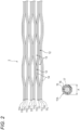
- Fig. 2 illustrates an example of the optical fiber ribbon 2 housed in the optical fiber cable 1A.
- the optical fiber ribbon 2 is an intermittent connection type optical fiber ribbon in which a connecting portion 12 in which the optical fibers adjacent to each other are connected to each other and a non-connecting portion 13 in which the optical fibers adjacent to each other are not connected to each other are intermittently provided in the longitudinal direction in a state where a plurality of optical fibers 11A to 11L are disposed in parallel to each other.
- Fig. 2 illustrates a plan view of the intermittent connection type optical fiber ribbon 2 in a state where the optical fibers 11A to 11L are opened in a disposition direction, and a cross-sectional view of the optical fiber 11A.
- a portion where the connecting portion 12 and the non-connecting portion 13 are provided intermittently may be between some optical fibers (intermittently provided every two cores), or may be between all the optical fibers (intermittently provided for each core).
- the non-connecting portion 13 is not provided between the optical fibers 11A and 11B, 11C and 11D, 11E and 11F, 11G and 11H, 11I and 11J, and 11K and 11L.
- the connecting portion 12 in the optical fiber ribbon 2 is formed by applying, for example, a connecting resin 14 formed of an ultraviolet curable resin, a thermosetting resin, or the like between the optical fibers.
- a connecting resin 14 formed of an ultraviolet curable resin, a thermosetting resin, or the like between the optical fibers.
- the connecting resin 14 may be applied to only one side surface of a parallel surface to be formed by the optical fibers 11A to 11L disposed in parallel to each other, or may be applied to both side surfaces thereof.
- the optical fiber ribbon 2 may be manufactured by, for example, applying a tape resin to one side surface or both side surfaces of the optical fibers 11A to 11L disposed in parallel to each other, connecting all the optical fibers 11A to 11L, and cutting off a part with a rotary blade or the like to form the non-connecting portion 13.
- the optical fibers 11A to 11L include, for example, a glass fiber 15 formed of a core and a clad, and two coating layers 16 and 17 covering an outer periphery of the glass fiber 15.
- the inner coating layer 16 of the two coating layers is formed of a primary resin.
- the outer coating layer 17 of the two coating layers is formed of a secondary resin.
- the optical fibers 11A to 11L are so-called small diameter core wires, and an outer diameter A thereof is, for example, 165 ⁇ m or more and 220 ⁇ m or less.
- the optical fibers 11A to 11L may be a multi-core fiber in which the number of cores per optical fiber is four or more. Since the multi-core fiber can send different information for each core, a transmission capacity per optical fiber can be increased.
- a soft resin having a relatively low Young's modulus is used as a buffer layer.
- a hard resin having a relatively high Young's modulus is used as a protective layer.
- the Young's modulus of the secondary resin at, for example, 23°C is 900 MPa or more, desirably 1,000 MPa or more, and more desirably 1,500 MPa or more.
- the secondary resin forming the outer coating layer 17 is a resin composition containing: a base resin containing a urethane acrylate oligomer or a urethane methacrylate oligomer, a monomer having a phenoxy group, a photopolymerization initiator, and a silane coupling agent; and a hydrophobic inorganic oxide particle.
- a content of the inorganic oxide particle in the resin composition is 1% by mass or more and 45% by mass or less based on a total amount of the resin composition.
- acrylate or methacrylate corresponding thereto will be referred to as (meth) acrylate.
- urethane (meth) acrylate oligomer an oligomer obtained by reacting a polyol compound, a polyisocyanate compound, and a hydroxyl group-containing (meth) acrylate compound can be used.
- This oligomer can be obtained, for example, by reacting polypropylene glycol, isophorone diisocyanate, hydroxyethyl acrylate, and methanol having a molecular weight of 4,000.
- the monomer having the phenoxy group a (meth) acrylate compound having the phenoxy group can be used.
- the monomer having the phenoxy group includes nonylphenol EO modified acrylate (a brand name "ARONIX M-113" of Toagosei Co., Ltd.), or the like.
- the photopolymerization initiator one of known radical photopolymerization initiators can be appropriately selected and used, and for example, the photopolymerization initiator includes 2,4,6-trimethylbenzoyldiphenylphosphine oxide or the like.
- the silane coupling agent is not particularly limited as long as the silane coupling agent does not interfere with the curing of the resin composition.
- the silane coupling agent includes 3-mercaptopropyltrimethoxysilane or the like.
- the hydrophobic inorganic oxide particle has a hydrophobic group introduced into a surface of the inorganic oxide particle.
- the inorganic oxide particle is, for example, a silica particle.
- the hydrophobic group may be a reactive group such as a (meth) acryloyl group, a vinyl group, or the like, or a non-reactive group such as a hydrocarbon group (for example, an alkyl group), an aryl group (for example, a phenyl group), or the like.
- a lateral pressure characteristic of the optical fibers 11A to 11L is improved by blending the inorganic oxide particle with the secondary resin forming the coating layer 17.
- the primary resin forming the coating layer 16 and the secondary resin are formed of, for example, an ultraviolet curable resin, a thermosetting resin, or the like.
- the optical fiber ribbon 2 When the optical fiber ribbon 2 is housed in the optical fiber cable 1A, the optical fiber ribbon 2 is in a state of being rolled to be gathered. Alternatively, a plurality of optical fiber ribbon 2 may be stranded together to form a unit, and the plurality of units may be in a state of being gathered. The plurality of optical fiber ribbons 2 in a state of being gathered may be bundled with a bundle material or the like, or may be bundled with the bundle material or the like for each unit.
- the ratio of a total cross-sectional area of the eight tensile strength members 5 (four tensile strength member units 50) to a cross-sectional area of the cable sheath 4 is 5.4% or more.
- An outer diameter of the optical fiber cable 1A is 6 mm or more and 16 mm or less, and for example, when the optical fiber cable 1A has the outer diameter of 10 mm, a thickness of the cable sheath 4 is 1.0 mm, and eight tensile strength members 5 having an outer diameter of 0.5 mm are provided in the cable sheath 4, the ratio of the total cross-sectional area becomes 5.6%.
- the bending rigidity in the radial direction of the optical fiber cable 1A is 0.35 N ⁇ m 2 or more and 1.3 N ⁇ m 2 or less in the whole circumference direction.
- the core density obtained by dividing the number of cores of all the optical fibers forming the plurality of optical fiber ribbons 2 by a cable cross-sectional area of the optical fiber cable 1A is 5.0 cores/mm 2 or more.
- the thickness of the cable sheath 4 is 1.0 mm
- the outer diameter A of the optical fiber is 200 ⁇ m
- the number of optical fiber ribbons 2 including 12 cores housed in the cable sheath 4 of the optical fiber cable 1A is 36, at that time, the number of cores of all optical fibers is 432 cores, and the core density is 5.5 cores/mm 2 .
- it is desirable that a unit weight of the optical fiber cable 1A is 100 kg/km or less.
- the optical fiber ribbon 2 including 12 cores is used in this example, for example, an optical fiber ribbon including 16 cores or 24 cores may be used.
- the optical fiber ribbon is housed in the optical fiber cable 1A, the optical fiber may be housed therein as it is without forming a tape shape.
- the optical fibers 11A to 11L have a bending loss equivalent to that of ITU-T G.657A2 in which the bending loss at a wavelength of 1,550 nm is 0.5 dB or less for a bending diameter of cp15 mm ⁇ 1 turn, and 0.1 dB or less for a bending diameter of ⁇ 20 mm ⁇ 1 turn.
- the tensile strength member unit 50 in which two of the tensile strength members 5 are configured to be paired with each other, is disposed in a well-balanced manner inside the cable sheath 4, bending anisotropy (bias in an easily bendable direction) of the optical fiber cable 1A can be prevented.
- the optical fiber cable 1A can have a good pneumatic feeding characteristic.
- the optical fiber cable 1A can be pneumatically fed into a micro-duct having a small inner diameter of 20 mm or less, and can also be housed in the micro-duct.
- the optical fiber cable 1A has a cable outer diameter of 6 mm or more, it is possible to prevent the occurrence of buckling when the optical fiber cable is pneumatically fed thereinto.
- the optical fiber cable 1A sets the bending rigidity in the radial direction thereof to a range of 0.35 N ⁇ m 2 or more and 1.3 N ⁇ m 2 or less in the whole circumferential direction, thereby making it possible to be provided with an appropriate bending rigidity suitable for the pneumatic feeding.
- the bending rigidity in the radial direction is 0.35 N ⁇ m 2 or more in the whole circumferential direction, it is possible to prevent the occurrence of buckling when the optical fiber cable 1A is pneumatically fed.
- the bending rigidity in the radial direction is 1.3 N ⁇ m 2 or less in the whole circumferential direction, such that when the extra length of the optical fiber cable 1A is stored in, for example, a hand hole or the like, the optical fiber cable 1A can be bundled to an appropriate size and has good storability.
- the tensile strength member 5 is formed of, for example, aramid FRP, a liquid crystal polymer, or the like.
- the aramid FRP, the liquid crystal polymer, or the like have a relatively high elastic modulus, the rigidity of the optical fiber cable 1A can be appropriately increased.
- the aramid FRP, the liquid crystal polymer, or the like have a relatively low linear expansion coefficient, it is possible to prevent shrinkage of the optical fiber cable 1A caused by shrinkage of the cable sheath 4 in a low temperature environment. Since the aramid FRP, the liquid crystal polymer, or the like are non-inductive, it is not required to provide a ground as a countermeasure against lightning.
- the resin of the cable sheath 4 contains the silicon-based release agent. According to this configuration, a friction coefficient of the cable sheath 4 can be reduced. Mass fraction of the silicon-based release agent contained in the cable sheath 4 is set to 1.5% or more, such that the friction coefficient of the cable sheath 4 can be more reliably reduced. Accordingly, when the optical fiber cable 1A is pneumatically fed into the duct, a friction between the cable sheath 4 and an inner wall of the duct can be reduced, such that a pneumatic feeding distance can be extended.
- the flame retardancy of the optical fiber cable 1A can be improved by forming the cable sheath 4 with flame-retardant PVC or flame-retardant polyethylene having an oxygen index of 50 or more.
- a cured product of the above-described resin composition is used as the outer coating layer 17 forming the coating of the optical fibers 11A to 11L, thereby making it possible to improve the lateral pressure resistance of the optical fibers 11A to 11L. Therefore, when the optical fiber ribbon 2 is formed by using such optical fibers 11A to 11L, it is possible to prevent an increase in transmission loss when the optical fiber ribbon 2 is housed in the optical fiber cable 1A.
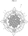
- An optical fiber cable 1B according to a second embodiment will be described with reference to Figs. 3 and 4 .
- the same configurations as those of the optical fiber cable 1A according to the first embodiment will be denoted by the same reference signs, and the description thereof will be omitted.
- Fig. 3 is a cross-sectional view perpendicular to a longitudinal direction of the optical fiber cable 1B.
- Fig. 4 is a side view of the optical fiber cable 1B illustrated in Fig. 3 .
- the optical fiber cable 1B includes a plurality of intermittent connection type optical fiber ribbons 2, the water absorbing tape 3 that covers the periphery of the optical fiber ribbon 2, the cable sheath 4 inside which the optical fiber ribbon 2 covered with the water absorbing tape 3 is housed, and the tensile strength member 5 and the tear string 6 that are provided inside the cable sheath 4.
- the optical fiber cable 1B includes a protrusion 7 on an outer peripheral portion of the cable sheath 4.
- a plurality of protrusions 7 are provided. As illustrated in Fig. 4 , the eight protrusions 7 are spirally provided along the longitudinal direction of the optical fiber cable 1B. Each protrusion 7 may be provided continuously along the longitudinal direction, or may be provided intermittently therealong. The eight protrusions 7 are provided at an approximately equal space in a circumferential direction of the outer peripheral portion of the cable sheath 4 in a cross section in a radial direction of the optical fiber cable 1B. The protrusion 7 is formed on the outer peripheral portion of the cable sheath 4 in a state of protruding in the radial direction of the optical fiber cable 1B.
- a surface 7a in a protruding direction of the protrusion 7 is formed with a curved surface, and is formed so that a radius of curvature of the curved surface is set to 2.5 mm or more.
- the protrusion 7 is formed to be integrated with the cable sheath 4 by extrusion molding.
- the eight protrusions 7 are spirally provided, and for example, may be provided linearly along the longitudinal direction of the optical fiber cable 1B.
- a plurality of protrusions 7 protruding in the radial direction of the optical fiber cable 1B are provided on the outer peripheral portion of the cable sheath 4. Therefore, when the optical fiber cable 1B is pneumatically fed into the duct, the protrusion 7 contacts the inner wall of the duct, such that a contact area between the cable sheath 4 and the duct can be reduced. Accordingly, the friction between the cable sheath 4 and the duct is reduced, such that the pneumatic feeding distance can be extended.
- the protrusion 7 of the cable sheath 4 is spirally formed along the longitudinal direction of the optical fiber cable 1B. Accordingly, when the optical fiber cable 1B is pneumatically fed into the duct, the inner wall of the duct and the cable sheath 4 of the optical fiber cable 1B are in a state of being close to point contact. Therefore, the friction between the two can be further reduced, such that the pneumatic feeding distance can be extended.
- evaluation of the pneumatic feeding distance is performed with respect to a sample of an optical fiber cable of each example, in which the type and number of tensile strength members 5 and the structure of the cable sheath 4 are different, and a sample of an optical fiber cable of each comparative example of a related-art structure.
- An evaluation result thereof is shown in Table 1. [Table 1] Sample No.
- samples Nos. 1 to 3 are comparative examples.
- the sample No. 1 is an optical fiber cable having a structure in which two tensile strength members are embedded in the cable sheath
- the samples Nos. 2 and 3 are optical fiber cables having a structure in which four tensile strength members are embedded in the cable sheath.
- Samples Nos. 4 to 8 and 11 are optical fiber cables having a structure in which eight tensile strength members, two of which are paired with each other, are embedded in the cable sheath, and correspond to the optical fiber cable of the first embodiment.
- a sample No. 9 has a structure in which the protrusion 7 is formed linearly along the longitudinal direction of the optical fiber cable 1B.
- a sample No. 10 has a structure in which the protrusion 7 is formed spirally along the longitudinal direction of the optical fiber cable 1B as illustrated in Fig. 4 .
- the tensile strength members of the samples Nos. 1, 2, and 4 are glass FRPs having an outer diameter of 0.5 mm.
- the tensile strength members of the samples Nos. 3 and 5 to 10 are aramid FRPs having an outer diameter of 0.5 mm.
- the tensile strength member of the sample No. 11 is a liquid crystal polymer having an outer diameter of 0.5 mm.
- the sample No. 6 is an optical fiber cable in which the silicon-based release agent of 1 wt% is added to the cable sheath
- the samples Nos. 7, 9, and 10 are optical fiber cables in which the silicon-based release agent of 1.5 wt% is added thereto
- the samples Nos. 8 and 11 are optical fiber cables in which the silicon-based release agent of 2.5 wt% is added thereto.
- the cable outer diameter of each sample is 10 mm.
- the maximum and minimum bending rigidity indicates a bending rigidity value in a direction of becoming the maximum bending rigidity and a bending rigidity value in a direction of becoming the minimum bending rigidity when each optical fiber cable is bent in the radial direction.
- a method for measuring the bending rigidity is in accordance with IEC60794 Stiffness (Method E17A). For example, in the case of the structure illustrated in Fig. 1 , the bending rigidity becomes a maximum value when the optical fiber cable is bent in a direction of the tensile strength member 5, and becomes a minimum value when the optical fiber cable is bent in a direction deviating by 45 degrees from the direction of the tensile strength member 5.
- the dynamic friction coefficient indicates a friction coefficient between the optical fiber cable that is pneumatically fed into the duct and the inner wall of the duct.
- a pneumatic feeding test in accordance with IEC is performed by using a pneumatic feeding device illustrated in Fig. 5 .
- a length of a pipe 20 is 1,000 m, and the pipe 20 is folded back every 100 m. Bending (R) of the pipe 20 is 40 times an outer diameter of the pipe, and an inner diameter of the pipe 20 is 14 mm.
- An opening 21 is an inlet for air and an optical fiber cable, and an opening 22 is an outlet for the air and the optical fiber cable.
- An air pressure is set to 1.3 MPa to 1.5 MPa.
- a sample, the pneumatic feeding distance of which is 1,800 m or more, is evaluated as S; a sample, the pneumatic feeding distance of which is 1,300 m or more and less than 1,800 m, is evaluated as A; a sample, the pneumatic feeding distance of which is 800 m or more and less than 1,300 m, is evaluated as B; and a sample, the pneumatic feeding distance of which is less than 800 m, is evaluated as C.
- the samples (the samples evaluated as S), the pneumatic feeding distance of which is 1,800 m or more, are Nos. 7 to 11; and the samples (the samples evaluated as A), the pneumatic feeding distance of which is 1,300 m or more and less than 1,800 m, are Nos. 4 to 6.
- the samples (the samples evaluated as B), the pneumatic feeding distance of which is 800 m or more and less than 1,300 m, are Nos. 2 and 3; and the sample (the sample evaluated as C), the pneumatic feeding distance of which is less than 800 m, is No. 1.
- the pneumatic feeding distance can be increased to 1,300 m or more by allowing a total of eight tensile strength members, two of which are paired with each other, to be embedded in the cable sheath.
- the samples (the samples evaluated as S), the pneumatic feeding distance of which is 1,800 m or more, are Nos. 7 to 11, it is found out that when the silicone-based release agent of 1.5 wt% or more is added to the cable sheath, the dynamic friction coefficient can be reduced to about one-third as compared with a case in which the silicone-based release agent is not added thereto, such that the pneumatic feeding distance could be significantly extended.
- the silicone-based release agent of 2.5 wt% when added to the cable sheath, the cable sheath becomes slightly soft, such that it is found out that the bending rigidity becomes smaller and an expansion rate of the pneumatic feeding distance becomes slower than those of the above-described case in which the silicone-based release agent of 1.5 wt% is added thereto.
- the silicon-based release agent is added in an amount of more than 2.5 wt%, winding collapse of the optical fiber cable occurs such that handleability thereof deteriorates. From this point, it is found out that an addition ratio of the silicone-based release agent is desirably 1.5 wt% or more and 2.5 wt% or less.
- the pneumatic feeding distance can be increased to 1,900 m or more by providing the protrusion on the cable sheath as in the samples Nos. 9 and 10. It is found out that the pneumatic feeding distance can be extended up to 2,000 m by providing the protrusion in the spiral shape along the longitudinal direction of the optical fiber cable.
- the secondary resin of the optical fibers 11A to 11L is examined. As a result, it is found out that by blending the inorganic oxide particle with the secondary resin, the lateral pressure characteristic of the optical fiber ribbon can be improved, and the core density can be increased by about 1.0 to 1.5 cores/mm 2 .
- An optical fiber cable 1C according to a third embodiment will be described with reference to Fig. 6 .
- the same configurations as those of the optical fiber cable 1A according to the first embodiment will be denoted by the same reference signs, and the description thereof will be omitted.
- Fig. 6 is a cross-sectional view perpendicular to a longitudinal direction of the optical fiber cable 1C.
- the optical fiber cable 1C includes a plurality of optical fiber ribbons 2, the water absorbing tape 3 that covers the periphery of the optical fiber ribbon 2, the cable sheath 4 that covers the periphery of the water absorbing tape 3, and the tensile strength member 5 and the tear string 6 that are provided inside the cable sheath 4.
- the optical fiber cable 1C includes the protrusion 7 on the outer peripheral portion of the cable sheath 4.
- a diameter of the optical fiber cable 1C is about 6 mm to 16 mm.
- Four tensile strength member units 50 in which two tensile strength members 5 are paired with each other, are provided.
- two pairs of two paired tensile strength member units 50 are disposed at locations facing each other with a center of the optical fiber cable 1C interposed therebetween in a cross section in a radial direction of the optical fiber cable 1C.
- a plurality of protrusions 7 are provided on a part of an outer peripheral portion 41 of the cable sheath 4. Each protrusion 7 is provided so as to protrude from the cable sheath 4 toward the outside in the radial direction of the optical fiber cable 1C.
- the protrusion 7 is formed so as to form a part of a circle in the cross section in the radial direction of the optical fiber cable 1C.
- the protrusion 7 is formed to be a shape having an outer circumference of a semicircle or more of a circle forming the protrusion 7.
- the eight protrusions 7 are provided on the outer peripheral portion 41 of the cable sheath 4 at an approximately equal space in the cross section in the radial direction of the optical fiber cable 1C.
- each of the protrusions 7 is provided along the longitudinal direction of the optical fiber cable 1C.
- Each protrusion 7 may be continuously provided along the longitudinal direction, or may be intermittently provided therealong.
- Each protrusion 7 may be provided linearly along the longitudinal direction of the optical fiber cable 1C, or may be provided spirally therealong.
- the protrusion 7 is formed to be integrated with the cable sheath 4.
- the protrusion 7 is formed by extrusion molding together with the cable sheath 4.
- Fig. 7 is an enlarged view schematically illustrating a cross section in the cable radial direction of the protrusion 7 and the outer peripheral portion 41.
- the protrusion 7 is formed so that a part of a circle A protrudes from the outer peripheral portion 41 in the cross section in the radial direction of the optical fiber cable 1C.
- a portion indicated by a diagonal line forms a fan shape B, and a central angle ⁇ 2 of the fan shape B is 180 degrees or more.
- intersections 8a and 8b between a surface 7a of the protrusion 7 and a surface 41a of the outer peripheral portion 41 which is not the protrusion 7 are formed on opposite side portions (left and right side portions in Fig. 7 ) of the protrusion 7, in the cross section in the cable radial direction.
- An angle ⁇ 1 formed by a tangent line 7b of the surface 7a and a tangent line 41b of the surface 41a at the intersections 8a and 8b is 90 degrees or less.
- a distance L between the intersections 8a and 8b of the protrusion 7 is smaller than a maximum width W (a diameter of the circle A in the protrusion 7) in the circumferential direction of the optical fiber cable 1C of the protrusion 7.
- the maximum width W is desirably 5 mm or less.
- the protrusion 7 is provided on the outer peripheral portion 41 of the cable sheath 4, a contact area between the optical fiber cable 1C and the inner surface of the duct can be reduced when the pneumatic feeding is performed. As a result, friction between the optical fiber cable 1C and the inner surface of the duct is reduced when the pneumatic feeding is performed, such that the pneumatic feeding distance can be extended.
- a shape of the protrusion 7 has a shape in which a part of the circle A protrudes from the outer peripheral portion 41 in the cross section in the radial direction of the optical fiber cable 1C, and the portion where the circle A protrudes from the outer peripheral portion 41 includes a portion of the fan shape B.
- the central angle ⁇ 2 of the fan shape B is formed to be 180 degrees or more.
- the angle ⁇ 1 formed by the tangent lines 7b and 41b between the surfaces at the intersections 8a and 8b between the surface 7a of the protrusion 7 and the surface 41a of the outer peripheral portion 41 which is not the protrusion 7 is formed to be 90 degrees or less.
- a blade such as a nipper or the like can be easily fixed to portions of the intersections 8a and 8b. Accordingly, when the protrusion 7 is cut, it is possible to prevent a state in which the nipper or the like slip and cutting the protrusion 7 becomes difficult. Therefore, the protrusion 7 can be easily removed, and airtightness can be maintained when the optical fiber cable is housed in a closure.
- the blade such as the nipper or the like can be inserted into the gap therebetween, such that the angle ⁇ 1 formed by the tangent lines 7b and 41b may be larger than 0 degrees so that the gap can be formed.
- the optical fiber cable 1C when the optical fiber cable 1C is mounted on the closure, for example, the optical fiber cable 1C may be caused to pass from an inlet of the closure to an outlet thereof and mounted thereon. In this case, it is required to remove the protrusion 7 in the middle of passing through the inlet of the closure and the outlet thereof among the protrusions 7 of the optical fiber cable 1C.
- the blade such as the nipper or the like is caused to be closer to the protrusion 7 from the radial direction of the optical fiber cable 1C, and the blade is opened to the maximum width W or more of the protrusion 7 to go over the protrusion 7.
- the blade such as the nipper or the like that goes over the protrusion 7 into the portions of the intersections 8a and 8b to cut the protrusion 7.
- the maximum width W of the protrusion 7 in the cable circumferential direction is set to 5 mm or less, such that the protrusion 7 can be cut by going over the protrusion 7 from the radial direction of the optical fiber cable 1C.
- an end portion of the optical fiber cable 1C may be inserted only into the inlet of the closure and mounted thereon.
- the embodiment is satisfied as long as the blade such as the nipper or the like can be opened at the distance L or more between the intersections 8a and 8b, such that for example, even when the maximum width W of the protrusion 7 is larger than 5 mm, the protrusion 7 can be easily cut off when a width of a base of the protrusion 7 is set to 5 mm or less.
- Fig. 8 is an enlarged view schematically illustrating a cross section in a cable radial direction of a protrusion 107 and the outer peripheral portion 41 of the comparative example.
- the protrusion 107 of the comparative example has a shape in which a part of the circle A protrudes from the outer peripheral portion 41 in the cross section in the radial direction of the optical fiber cable.
- the protrusion 107 of the comparative example is different from the protrusion 7 of the third embodiment in that the central angle ⁇ 2 of the fan shape B forming an arc of a surface 107a is formed to be less than 180 degrees (about 100 degrees in the example of Fig. 8 ).
- the angle ⁇ 1 formed by the tangent lines 107b and 41b between the surfaces at the intersections 8a and 8b between the surface 107a of the protrusion 107 and the surface 41a of the outer peripheral portion 41, which is not the protrusion 107, is formed to be larger than 90 degrees (in the example of Fig. 8 , about 135 degrees).
- Samples Nos. 1 to 6 of optical fiber cables, in which the maximum width W of the protrusion and the angle ⁇ 1 are different in the protrusion 7 of the optical fiber cable 1A according to the third embodiment or the protrusion 107 of the comparative example, are prepared.
- the diameter of the optical fiber cables of the samples Nos. 1 to 6 is set to 12 mm.
- the pneumatic feeding distance, ease of protrusion removal, and airtightness are evaluated for the samples Nos. 1 to 6. An evaluation result thereof is shown in Table 2 below. [Table 2] Sample No.
- the maximum width W of the protrusion is 6 mm with respect to the samples Nos. 1 and 2, 5 mm with respect to the samples Nos. 3 and 4, and 4 mm with respect to the samples Nos. 5 and 6.
- the samples Nos. 1, 3, and 5 are optical fiber cables 1C of the example 2 in which the angle ⁇ 1 is 90 degrees or less.
- the samples Nos. 2, 4, and 6 are optical fiber cables of the comparative example in which the angle ⁇ 1 is larger than 90 degrees.
- a micro-duct pneumatic feeding test in accordance with IEC is performed by using the pneumatic feeding device illustrated in Fig. 5 .
- a length of the pipe 20 is 1,000 m, and the pipe 20 is folded back every 100 m.
- the bending (R) of the pipe 20 is 40 times the outer diameter of the pipe, and the inner diameter of the pipe 20 is 14 mm.
- the opening 21 is the inlet for the air and the optical fiber cable, and the opening 22 is the outlet for the air and the optical fiber cable.
- the air pressure is set to 1.3 MPa to 1.5 MPa.
- the ease of the protrusion removal is evaluated by cutting the protrusion using a cutting tool such as a nipper or the like.
- the airtightness of the closure when the optical fiber cable is housed in the closure is evaluated.
- a sample, the pneumatic feeding distance of which exceeds 1,000 m, is evaluated as A; a sample, the pneumatic feeding distance of which is 1,000 m, is evaluated as B; and a sample, the pneumatic feeding distance of which is less than 1,000 m, is evaluated as C.
- a sample, the protrusion removal of which is easily performed is evaluated as A; a sample, in which the protrusion removal can be performed but the blade such the nipper or the like is difficult to be inserted, is evaluated as B; and a sample, the protrusion removal of which is difficult, is evaluated as C.
- the sample In the evaluation of the airtightness, the sample, the ease of the protrusion removal of which is evaluated as A or B, is housed in the closure with the protrusion removed, and the airtightness of the closure is evaluated.
- a sample, the airtightness of which is good is evaluated as A; a sample, the airtightness of which is maintained by deformation of a grommet, is evaluated as B; and a sample, the airtightness of which is poor, is evaluated as C.
- the samples (the samples evaluated as A), the pneumatic feeding distance of which exceeds 1,000 m, are Nos. 3, 4, 5, and 6.
- the samples (the samples evaluated as B), the pneumatic feeding distance of which is 1,000 m, are Nos. 1 and 2. Accordingly, in the optical fiber cable having a diameter of 12 mm, it is found out that when the maximum width W of the protrusion is 5 mm or less, the pneumatic feeding exceeding 1,000 m can be performed.
- the samples (the samples evaluated as A), the protrusion removal of which is easily performed are Nos. 3 and 5.
- the sample (the sample evaluated as B), in which the protrusion removal can be performed but the blade such the nipper or the like is difficult to be inserted into the protrusion is No. 1.
- the samples (the sample evaluated as C), the protrusion removal of which is difficult are Nos. 2, 4, and 6. Accordingly, when the angle ⁇ 1 is 90 degrees or less and the maximum width W of the protrusion is 5 mm or less in the protrusion of the optical fiber cable, it is found out that the protrusion removal can be easily performed.
- the angle ⁇ 1 is 90 degrees or less and the maximum width W of the protrusion is larger than 5 mm, it is found out that it is difficult to insert the blade such as the nipper or the like toward the protrusion, but the protrusion can be removed.
- the angle ⁇ 1 is larger than 90 degrees, it is found out that the protrusion removal is difficult to be performed regardless of the size of the maximum width W of the protrusion.
- the samples (the samples evaluated as A), the airtightness of which is good are, Nos. 1, 3, and 5.
- the samples (evaluated as C), the airtightness of which is poor, are Nos. 4 and 6. Accordingly, it is found out that in the optical fiber cable, when the angle ⁇ 1 is 90 degrees or less, the protrusion can be removed even though the maximum width W of the protrusion is 5 mm or less or larger than 5 mm, and the airtightness can be improved by removing the protrusion.
- the maximum width W becomes too large, for example, larger than 5 mm, it is difficult to remove the protrusion with the nipper or the like, such that it is required to limit the maximum width W up to about several tens of mm at the maximum.
- An optical fiber cable 1D according to a fourth embodiment will be described with reference to Fig. 9 .
- the same configurations as those of the optical fiber cable 1A according to the first embodiment will be denoted by the same reference signs, and the description thereof will be omitted.
- Fig. 9 is a perspective view illustrating a configuration of the optical fiber cable 1D according to the fourth embodiment.
- the optical fiber cable 1D includes a plurality of optical fiber ribbons 2, the water absorbing tape 3 that covers the periphery of the optical fiber ribbon 2, the cable sheath 4 that covers the periphery of the water absorbing tape 3, and the tensile strength member unit 50, in which two tensile strength members 5 are configured to be paired with each other, and the tear string 6 that are provided inside the cable sheath 4.
- the cable sheath 4 includes a concave portion 42 on a surface thereof.
- a convex portion 43 is provided on the surface of the cable sheath 4 other than the concave portion 42.
- the concave portion 42 and the convex portion 43 are alternately provided on the surface of the cable sheath 4 so as to be adjacent to each other in a cross section in a radial direction of the optical fiber cable 1D.
- four concave portions 42 and four convex portions 43 are provided in the cross section in the radial direction of the optical fiber cable 1D.
- the four concave portions 42 and the four convex portions 43 are provided on the surface of the cable sheath 4 at an approximately equal space in the cross section in the radial direction of the optical fiber cable 1D.
- the number of concave portions 42 and convex portions 43 is not limited to four.
- the concave portion 42 is a portion in which a diameter of the optical fiber cable 1D is smaller than a portion of the convex portion 43 in the cross section in the radial direction of the cable sheath 4.
- the concave portion 42 is continuously provided linearly along a longitudinal direction of the optical fiber cable 1D.
- the convex portion 43 is also provided along the longitudinal direction of the optical fiber cable 1D, and the convex portion 43 may be continuously provided along the longitudinal direction thereof, or may be intermittently provided therealong.
- the concave portion 42 and the convex portion 43 may be provided linearly along the longitudinal direction of the optical fiber cable 1D, or may be provided spirally therealong.
- the concave portion 42 and the convex portion 43 of this example are continuously provided linearly along the longitudinal direction of the optical fiber cable 1D.
- the concave portion 42 and the convex portion 43 are formed to be integrated with each other by, for example, extrusion molding.
- an end surface 43a in a direction in which the convex portion 43 protrudes is formed in a curved surface having a constant curvature, and is not limited thereto.
- the end surface 43a may be formed in a combination of a curved surface having a different curvature and a flat surface.
- the surface of the concave portion 42 may also not be formed in an arc-shaped curved surface, or may be formed in, for example, a combination of a curved surface having a different curvature and a flat surface.
- a ratio of a width Wc of the concave portion 42 in a circumferential direction of the cable sheath 4 to a width Wv of the convex portion 43 in the circumferential direction of the cable sheath 4 is formed to be smaller than 2:1. That is, the width Wc of the concave portion 42 and the width Wv of the convex portion 43 are formed so as to satisfy a relationship of Wc ⁇ 2Wv.
- the width Wc of the concave portion 42 is formed to be 3 mm or more.
- the width Wc can vary depending on, for example, the outer diameter of the optical fiber cable 1D.
- An identification display (a marking) 9 for identifying the optical fiber cable 1D is provided on the surface of the cable sheath 4.
- the identification display 9 is provided only on the concave portion 42 of the cable sheath 4.
- the identification display 9 includes information such as, for example, a product name, a company name, the number of optical fiber cores housed in the optical fiber cable 1D, a length (a location) of the cable, the year of manufacture, or the like.
- a size of a character, a number, or the like provided in the identification display 9 is, for example, 2 mm or more in the longitudinal direction.
- a size of the identification display 9 can be changed depending on a size of the width Wc of the concave portion 42.
- the identification display 9 is printed by spraying ink onto the concave portion 42 by using an inkjet printer.
- the identification display 9 is printed by transferring toner to the concave portion 42 by using a laser printer.
- the identification display 9 may be formed by, for example, a hot stamping method in which a stamp is pressed against the concave portion 42 to engrave a character, a number, or the like.
- the identification display 9 may be, for example, a color band colored in a band shape extending along the longitudinal direction of the cable on the surface of the concave portion 42.
- the color band may be provided together with the character, the number, or the like.
- the color band is formed by simultaneously extruding a material, the color of which is different from that of a sheath main body portion from a die during the extrusion molding of the cable sheath 4.
- the outer diameter of the optical fiber cable 1D is, for example, 16 mm or less when an inner diameter of the micro-duct, into which the optical fiber cable 1D is pneumatically fed, is 20 mm or less.
- the outer diameter of the optical fiber cable 1D is 11 mm or less.
- the core density obtained by dividing the number of cores of all the optical fibers forming the plurality of optical fiber ribbons 2 by a cable cross-sectional area of the optical fiber cable 1D is desirably 5.0 cores/mm 2 or more.
- the outer diameter of the optical fiber cable 1D is 10 mm
- the thickness of the cable sheath 4 is 1.0 mm
- the outer diameter of the optical fiber is 200 ⁇ m
- the number of optical fiber ribbons 2 including 12 cores housed in the cable sheath 4 of the optical fiber cable 1D is 36, at that time, the number of cores of all the optical fibers is 432 cores, and the core density is 5.5 cores/mm 2 .
- the bending rigidity of the optical fiber cable 1D in the radial direction is desirably 0.35 N ⁇ m 2 or more and 1.3 N ⁇ m 2 or less in the whole circumferential direction.
- the tensile strength member 5 is formed of the aramid FRP, and, for example, when the outer diameter of the optical fiber cable 1D is 10 mm and the thickness of the cable sheath 4 is 1.0 mm, the outer diameter of the aramid FRP is desirably 0.5 mm or more.
- the optical fiber cable 1D includes the plurality of optical fiber ribbons 2 and the cable sheath 4 inside which the optical fiber ribbons 2 are housed and including the concave portion 42 on the surface thereof.
- the identification display 9 is provided only on the concave portion 42. According to this configuration, when the optical fiber cable 1D is pneumatically fed, the concave portion 42 is difficult to contact the inner surface of the duct, such that there is little risk that the identification display 9 provided on the concave portion 42 is scraped off by rubbing against the inner surface of the duct. Therefore, the visibility of the identification display 9 provided on the cable sheath 4 can be maintained high.
- the concave portion 42 is provided on the surface of the cable sheath 4 to form a structure in which the surface thereof becomes uneven, the contact area between the optical fiber cable 1D and the inner surface of the duct is reduced, such that the friction between the surface of the cable sheath 4 and the inner surface of the duct during the pneumatic feeding can be reduced. Accordingly, the pneumatic feeding distance can be extended when the optical fiber cable 1D is pneumatically fed into the duct. Since the identification display 9 is provided only on the concave portion 42 on the surface of the cable sheath 4, the identification display 9 does not overlap at a boundary between the concave portion 42 and the convex portion 43, and the visibility of the number, the character, or the like provided in the identification display 9 can be improved.
- the optical fiber cable 1D is printed with the number, the character, or the like of the identification display 9 by the inkjet printer or the laser printer, which are generally considered as printers having a high printing speed. Therefore, since the time required for a step of forming the identification display 9 can be shortened, manufacturing efficiency of the optical fiber cable 1D can be improved.
- the optical fiber cable 1D is formed so that the width Wc of the concave portion 42 on the surface of the cable sheath 4 is formed to be 3 mm or more. Therefore, the concave portion 42 of the cable sheath 4 can be provided with the identification display 9 including the character, the number, or the like of 2 mm or more, which are generally considered to be easily and visually recognized by the naked eye. Therefore, the visibility of the identification display 9 in the optical fiber cable 1D can be improved.
- the concave portion 42 may contact the inner surface of the duct, and the identification display 9 provided on the concave portion 42 may be scraped off.
- the concave portion 42 contacts the inner surface of the duct, the friction between the surface of the cable sheath 4 and the inner surface of the duct becomes large.
- the ratio of the width Wc of the concave portion 42 to the width Wv of the convex portion 43 is formed to be smaller than 2:1. Accordingly, it is possible to prevent the concave portion 42 from contacting the inner surface of the duct, thereby making it possible to prevent the identification display 9 from being scraped off. Since the convex portion 43 can contact the inner surface of the duct, it is possible to prevent the friction between the surface of the cable sheath 4 and the inner surface of the duct from becoming large, such that sufficiently long pneumatic feeding distance can be achieved.
- the outer diameter of the optical fiber cable is 10 mm.
- the number of concave portions (convex portions) of the cable sheath is four, which is the same as the number of concave portions (convex portions) of the optical fiber cable 1D illustrated in Fig. 9 .
- a character and a number of 2 mm are printed in the concave portion by using an inkjet printer.
- the visibility of the identification display is visually determined based on whether the printed character and number can be visually recognized and distinguished from other characters and numbers (for example, whether the printed number is "8" or "0" can be identified).
- a micro-duct pneumatic feeding test in accordance with IEC is performed by using the pneumatic feeding device illustrated in Fig. 5 .
- the length of the pipe 20 is 1,000 m, and the pipe 20 is folded back every 100 m.
- the bending (R) of the pipe 20 is 40 times the outer diameter of the pipe, and the inner diameter of the pipe 20 is 14 mm.
- the opening 21 is the inlet for the air and the optical fiber cable, and the opening 22 is the outlet for the air and the optical fiber cable.
- the air pressure is set to 1.3 MPa to 1.5 MPa.
- a sample having a good visibility is evaluated as A; a sample which can be visible is evaluated as B; and a sample which is difficult to be visible is evaluated as C.
- the samples (the samples evaluated as A) having a good visibility are Nos. 2 to 7.
- the sample (the sample evaluated as B) which can be visible is No. 1. Accordingly, it is found out that the visibility of the identification display is good when the width of the concave portion is 3 mm or more.
- the width of the concave portion is 2.5 mm, it is possible to print the character or the like of 2 mm in the concave portion, but due to manufacturing variations, the identification display may overlap at the boundary between the concave portion and the convex portion, and in this case, it is found out that the identification display can be visible but the visibility of the identification display is not good.
- An optical fiber cable 1E according to a fifth embodiment will be described with reference to Fig. 10 .
- the same configurations as those of the optical fiber cable 1A according to the first embodiment will be denoted by the same reference signs, and the description thereof will be omitted.
- the optical fiber cable 1E illustrated in Fig. 10 is a slotless type.
- the optical fiber cable 1E includes a round-shaped gathering core 111 and a cable sheath 113 formed around a periphery of the gathering core 111.
- a plurality of intermittent type optical fiber ribbons 2 including 12 cores are housed in the gathering core 111.
- the gathering core 111 of the optical fiber cable 1E is, for example, longitudinally or spirally wrapped with the water absorbing tape 3 to form a round shape.
- An outside of the water absorbing tape 3 is covered with the cable sheath 113 formed of two types of polyethylene (PE).
- PE polyethylene
- the cable sheath 113 an inner layer 114 which will be described later
- four tensile strength member units 50 in which, for example, two tensile strength members (tension members) 5 for maintaining strength in the longitudinal direction are configured to be paired with each other, and two tear strings 6 for tearing the cable sheath 113 in the longitudinal direction of the cable are longitudinally wrapped therearound and embedded therein during the extrusion molding of the cable sheath 113 (the inner layer 114).
- wire rods having a proof stress against tension and compression such as, for example, a steel wire, Fiber Reinforced Plastics (FRP), or the like are used.
- FRP Fiber Reinforced Plastics
- two of the four tensile strength member units 50, which are paired with each other, are provided on opposite sides with the gathering core 111 interposed therebetween.
- the locations of the respective tensile strength member units 50 are locations where two straight lines respectively connecting the two paired tensile strength member units 50 are orthogonal to each other.
- the tear strings 6 are respectively provided on opposite sides with the gathering core 111 interposed therebetween.
- the tear string 6 is, for example, a string-shaped member having a circular cross section using a resin material such as nylon, polyester, or the like, and the tear strings 6 are disposed, for example, on the same straight line along a radial direction of the gathering core 111.
- the cable sheath 113 is formed of two layers including the inner layer 114 and the outer layer 115.
- the inner layer 114 is in contact with the gathering core 111, and the outer layer 115 is provided on an outside of the inner layer 114 and covers an outside of the tensile strength member 5.
- a density thereof is 0.942 (g/cm 3 ) or more and 0.98 (g/cm 3 ) or less (for example, 0.95 (g/cm 3 )), and a tensile elastic modulus thereof is 700 to 1,200 (MPa).
- the material having the density of 0.942 (g/cm 3 ) or more is also referred to as high-density polyethylene (HDPE).
- the outer layer 115 of the cable sheath 113 is formed of HDPE, and the friction coefficient thereof is lowered, such that the micro-duct cable can easily pass through the duct.
- the outer layer 115 is formed of HDPE, the outer layer is hard such that the outer layer can sufficiently withstand the pneumatic feeding even though the pneumatic feeding supplied into the duct is increased or the micro-duct cable is pushed into the duct.
- the cable sheath 113 is formed of HDPE only, the tensile elastic modulus is high, such that the optical fiber ribbon 2 in the gathering core 111 is compressed and bent due to shrinkage of the cable sheath 113 at low temperature, which causes an increase in loss. In this case, as illustrated in Fig.
- a density thereof is 0.91 (g/cm 3 ) or more and less than 0.942 (g/cm 3 ) (for example, 0.93 (g/cm 3 )), and a tensile elastic modulus thereof is 100 to 600 (MPa), such that the shrinkage thereof is hard to occur at low temperature and thus the increase in attenuation at low temperature is prevented.
- the material having the density of less than 0.942 (g/cm 3 ) is referred to as low density polyethylene (LDPE) for convenience in order to distinguish between HDPE and LDPE.
- Fig. 11 is a table illustrating a specification and an evaluation result of each sample.
- a sheath thickness of LDPE of the inner layer 114 (the tensile elastic modulus is 300 (MPa)) and a sheath thickness of HDPE of the outer layer 115 (the tensile elastic modulus is 1,050 (MPa)) are respectively changed; a surface friction coefficient, an amount of change in attenuation at low temperature, a synthetic tensile elastic modulus, and a synthetic tensile elastic modulus ⁇ a sheath total cross-sectional area value (also referred to as ES product) are obtained; and whether or not each condition is suitable for the optical fiber cable for pneumatic feeding (A when suitable, B when not suitable) are evaluated.
- the surface friction coefficient is a friction coefficient of the cable surface of the optical fiber cable 1E.
- the amount of change in attenuation at low temperature (dB/km) is an amount of change in attenuation when the optical fiber cable 1E is left at low temperature (- 40°C).
- the synthetic tensile elastic modulus (MPa) is a tensile elastic modulus of a material obtained by combining the inner layer 114 and the outer layer 115 and converting the combined inner layer 114 and outer layer 115 into one member, and is obtained by using a cross-sectional area ratio of the inner layer 114 and the outer layer 115.
- the ES product (N) is the product of the synthetic tensile elastic modulus (MPa) and the sheath total cross-sectional area value (mm 2 ), and is one of the indexes of the strength of the cable sheath 113.
- the synthetic tensile elastic modulus corresponds to a "synthetic tensile elastic modulus of the cable sheath" according to the present disclosure
- the sheath total cross-sectional area value corresponds to a "total cross-sectional area of the cable sheath” according to the present disclosure.
- the outer diameter of the cable (the outer diameter of the optical fiber cable 1E) is set to ⁇ 12 (mm)
- the inner diameter of the cable (the outer diameter of the gathering core 111) is set to ⁇ 8 (mm)
- the LDPE sheath thickness is set to 2 (mm)
- the HDPE sheath thickness is set to 0 (mm) (referred to as a sample 1)
- the LDPE cross-sectional area is 62.8 (mm 2 )
- the HDPE cross-sectional area is 0 (mm 2 )
- the HDPE area ratio is 0 (%).
- the HDPE area ratio corresponds to a "ratio of the cross-sectional area of the outer layer to the total cross-sectional area of the cable sheath" according to the present disclosure.
- the ES product is 18,850 (N), and the amount of change in attenuation at low temperature is as low as 0.05 (dB/km), but the surface friction coefficient becomes as large as 0.5, which causes the sample 1 to be difficult to pass through the duct, such that it is determined that the sample 1 is not suitable for the optical fiber cable for pneumatic feeding (evaluation B).
- the bending rigidity is 0.1 (N ⁇ m 2 ), and in consideration of this point as well, the bending rigidity value is not sufficient enough for allowing the sample 1 to pass through the duct.
- the outer diameter of the cable is set to cp 12 (mm)
- the inner diameter of the cable is set to ⁇ 8 (mm)
- the LDPE sheath thickness is set to 1 (mm)
- the HDPE sheath thickness is set to 1 (mm) (referred to as a sample 2)
- the LDPE cross-sectional area is 28.3 (mm 2 )
- the HDPE cross-sectional area is 34.6 (mm 2 )
- the HDPE cross-section area ratio is 55 (%).
- the surface friction coefficient is 0.15
- the ES product is 44,768 (N)
- the amount of change in attenuation at low temperature is 0.15 (dB/km).
- the surface friction coefficient becomes small, and the amount of change in attenuation at low temperature is equal to or less than 0.2 (dB/km) which is a predetermined reference value, such that it is determined that the sample 2 is suitable for the optical fiber cable for pneumatic feeding (evaluation A).
- the bending rigidity is 0.85 (N ⁇ m 2 ), which is a value sufficient enough for allowing the sample 2 to pass through the duct.
- the outer diameter of the cable is set to ⁇ 12 (mm)
- the inner diameter of the cable is set to ⁇ 8 (mm)
- the LDPE sheath thickness is set to 0 (mm)
- the HDPE sheath thickness is set to 2 (mm)
- the LDPE cross-sectional area is 0.0 (mm 2 )
- the HDPE cross-sectional area is 62.8 (mm 2 )
- the HDPE area ratio is 100 (%).
- the surface friction coefficient is 0.15
- the ES product is 65,973 (N), which is greater than 60,000 (N).
- the amount of change in attenuation at low temperature is 0.22 (dB/km), which does not satisfy the predetermined reference value of 0.2 (dB/km) or less, and the increase in attenuation at low temperature cannot be avoided, such that it is determined that the sample 3 is not suitable for the optical fiber cable for pneumatic feeding (evaluation B).
- the bending rigidity is 1.5 (N ⁇ m 2 ).
- the outer diameter of the cable is set to cp16 (mm)
- the inner diameter of the cable is set to ⁇ 12 (mm)
- the LDPE sheath thickness is set to 2 (mm)
- the HDPE sheath thickness is set to 0 (mm) (referred to as a sample 4)
- the LDPE cross-sectional area is 88.0 (mm 2 )
- the HDPE cross-sectional area is 0 (mm 2 )
- the HDPE area ratio is 0 (%).
- the ES product is 26,389 (N), and the amount of change in attenuation at low temperature is 0.05 (dB/km), but the surface friction coefficient becomes as large as 0.5, which causes the sample 4 to be difficult to pass through the duct, such that it is determined that the sample 4 is not suitable for the optical fiber cable for pneumatic feeding (evaluation B).
- the bending rigidity is 0.1 (N ⁇ m 2 ), and in consideration of this point as well, the bending rigidity value is not sufficient enough for allowing the sample 4 to pass through the duct.
- the outer diameter of the cable is set to ⁇ 16 (mm)
- the inner diameter of the cable is set to ⁇ 12 (mm)
- the LDPE sheath thickness is set to 1.1 (mm)
- the HDPE sheath thickness is set to 0.9 (mm)
- the LDPE cross-sectional area is 45.3 (mm 2 )
- the HDPE cross-sectional area is 42.7 (mm 2 )
- the HDPE area ratio is 49 (%).
- the surface friction coefficient is 0.15
- the ES product is 58,410 (N)
- the amount of change in attenuation at low temperature is 0.18 (dB/km).
- the surface friction coefficient becomes small, and the amount of change in attenuation at low temperature is equal to or less than 0.2 (dB/km) which is the predetermined reference value, such that it is determined that the sample 5 is suitable for the optical fiber cable for pneumatic feeding (evaluation A).
- the bending rigidity is 0.7 (N ⁇ m 2 ).
- the outer diameter of the cable is set to ⁇ 16 (mm)
- the inner diameter of the cable is set to ⁇ 12 (mm)
- the LDPE sheath thickness is set to 0 (mm)
- the HDPE sheath thickness is set to 2 (mm)
- the LDPE cross-sectional area is 0 (mm 2 )
- the HDPE cross-sectional area is 88.0 (mm 2 )
- the HDPE area ratio is 100 (%).
- the surface friction coefficient is 0.15
- the ES product is 92,363 (N), which is greater than 60,000 (N).
- the amount of change in attenuation at low temperature is 0.25 (dB/km), which does not satisfy the predetermined reference value of 0.2 (dB/km) or less, and the increase in attenuation at low temperature cannot be avoided, such that it is determined that the sample 6 is not suitable for the optical fiber cable for pneumatic feeding (evaluation B).
- the bending rigidity is 1.5 (N ⁇ m 2 ).
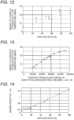
- Fig. 12 is a diagram illustrating a relationship between the amount of change in attenuation at low temperature and the HDPE area ratio. As the HDPE area ratio decreases, the amount of change in attenuation at low temperature also gradually decreases. It is found out that when the HDPE area ratio is 60 (%) or less, the amount of change in attenuation at low temperature can be reduced to the predetermined reference value (0.2 (dB/km)) or less. As described above, when the HDPE area ratio is set to 60 (%) or less, it is possible to prevent the increase in attenuation at low temperatures even though the outer layer 115 is formed of HDPE.
- Fig. 13 is a diagram illustrating a relationship between the amount of change in attenuation at low temperature and the ES product. As the ES product decreases, the amount of change in attenuation at low temperature also gradually decreases. It is found out that when the ES product is 60,000 (N) or less, the amount of change in attenuation at low temperature can be reduced to the predetermined reference value (0.2 (dB / km)) or less. As described above, when the ES product is set to 60,000 (N) or less, it is possible to prevent the increase in attenuation at low temperatures even though the outer layer 115 is formed of HDPE.
- Fig. 14 is a diagram illustrating a relationship between the bending rigidity and the HDPE area ratio. As the HDPE area ratio increases, the bending rigidity also increases. It is found out that when the HDPE area ratio is 20 (%) or more, the bending rigidity becomes the predetermined reference value of 0.3 (N ⁇ m 2 ) or more. Therefore, when the HDPE area ratio is set to 20 (%) or more, the optical fiber cable easily passes through the duct and can sufficiently withstand the pneumatic feeding.
- An optical fiber cable 1F according to a sixth embodiment will be described with reference to Fig. 15 .
- the same configurations as those of the optical fiber cable 1B according to the second embodiment will be denoted by the same reference signs, and the description thereof will be omitted.
- Fig. 15 is a cross-sectional view illustrating a configuration of the optical fiber cable 1F according to the sixth embodiment.
- the optical fiber cable 1F includes a plurality of optical fiber ribbons 2, the water absorbing tape 3 that covers the periphery of the optical fiber ribbon 2, the cable sheath 4 that covers the periphery of the water absorbing tape 3, the tensile strength member 5 and the tear string 6 that are provided inside the cable sheath 4, and the protrusion 7 provided on the outer peripheral portion of the cable sheath 4.
- the optical fiber cable 1F is different from the optical fiber cable 1B in that the tensile strength member unit 50 is formed of three tensile strength members 5.
- the optical fiber cable 1F is different from the optical fiber cable 1B in that only two protrusions 7 are provided at locations facing each other in the circumferential direction of the outer peripheral portion of the cable sheath 4 in a cross section in a radial direction of the optical fiber cable 1F.
- An optical fiber cable 1G according to a seventh embodiment will be described with reference to Fig. 16 .
- the same configurations as those of the optical fiber cable 1B according to the second embodiment will be denoted by the same reference signs, and the description thereof will be omitted.
- Fig. 16 is a cross-sectional view illustrating a configuration of the optical fiber cable 1G according to the seventh embodiment.
- the optical fiber cable 1G includes a plurality of optical fiber ribbons 2, the water absorbing tape 3 that covers the periphery of the optical fiber ribbon 2, the cable sheath 4 that covers the periphery of the water absorbing tape 3, the tensile strength member 5 and the tear string 6 that are provided inside the cable sheath 4, and the protrusion 7 provided on the outer peripheral portion of the cable sheath 4.
- the optical fiber cable 1G is different from the optical fiber cable 1B in that a pair of the tensile strength member units 50 is additionally provided as compared with the optical fiber cable 1B.
- the optical fiber cable 1G is different from the optical fiber cable 1B in that only two protrusions 7 are provided at locations facing each other in the circumferential direction of the outer peripheral portion of the cable sheath 4 in a cross section in a radial direction of the optical fiber cable 1G.
Landscapes
- Physics & Mathematics (AREA)
- General Physics & Mathematics (AREA)
- Optics & Photonics (AREA)
- Light Guides In General And Applications Therefor (AREA)
- Communication Cables (AREA)
Claims (15)
- Câble (1A, 1B, 1C, 1D, 1E, 1F, 1G) à fibres optiques, comprenant :une pluralité de fibres optiques ou une pluralité de rubans (2) de fibres optiques ;une gaine (4, 113) de câble à l'intérieur de laquelle sont logés une pluralité des fibres optiques ou une pluralité des rubans (2) de fibres optiques ; etquatre unités (50) ou plus d'éléments de résistance à la traction qui sont disposées de manière à être encastrées à l'intérieur de la gaine (4, 113) de câble, et dans chacune desquelles deux éléments (5) de résistance à la traction ou plus sont appariés l'un à l'autre,dans lequel les quatre unités (50) ou plus d'éléments de résistance à la traction sont respectivement disposées à des emplacements se faisant face avec un centre du câble (1A, 1B, 1C, 1D, 1E, 1F, 1G) à fibres optiques interposé entre celles-ci dans une section transversale dans une direction radiale du câble (1A, 1B, 1C, 1D, 1E, 1F, 1G) à fibres optiques,caractérisé en ce que la rigidité à la flexion dans la direction radiale du câble (1A, 1B, 1C, 1D, 1E, 1F, 1G) à fibres optiques est de 0,35 N·m2 ou plus et de 1,3 N·m2 ou moins dans toutes les directions,en ce que, en outre,un rapport d'une superficie totale en section transversale des éléments (5) de résistance à la traction sur une superficie en section transversale de la gaine de câble est de 5,4 % ou plus,en ce que, en outre,une densité de noyaux obtenue en divisant un nombre de noyaux de la pluralité des fibres optiques ou un nombre de noyaux de fibres optiques formant la pluralité de rubans (2) de fibres optiques par une superficie en section transversale de câble du câble (1A, 1B, 1C, 1D, 1E, 1F, 1G) à fibres optiques est de 5,0 noyaux/mm2 ou plus, eten ce queun diamètre externe de câble du câble (1A, 1B, 1C, 1D, 1E, 1F, 1G) à fibres optiques est de 6 mm ou plus et de 16 mm ou moins.
- Câble (1A, 1B, 1C, 1D, 1E, 1F, 1G) à fibres optiques selon la revendication 1,
dans lequel au moins quatre unités (50) d'éléments de résistance à la traction des quatre unités ou plus d'éléments de résistance à la traction du câble à fibres optiques sont disposées à des emplacements où des lignes droites reliant respectivement une paire des unités (50) d'éléments de résistance à la traction sont mutuellement orthogonales dans la section transversale dans la direction radiale du câble (1A, 1B, 1C, 1D, 1E, 1F, 1G) à fibres optiques - Câble (1A, 1B, 1C, 1D, 1E, 1F, 1G) à fibres optiques selon la revendication 1 ou revendication 2,
dans lequel les éléments (5) de résistance à la traction sont un FRF aramide. - Câble (1A, 1B, 1C, 1D, 1E, 1F, 1G) à fibres optiques selon la revendication 1 ou revendication 2,
dans lequel les éléments (5) de résistance à la traction sont un polymère à cristaux liquides. - Câble (1A, 1B, 1C, 1D, 1E, 1F, 1G) à fibres optiques selon l'une quelconque des revendications 1 à 4,
dans lequel la gaine (4, 113) de câble contient un agent de démoulage à base de silicone. - Câble (1A, 1B, 1C, 1D, 1E, 1F, 1G) à fibres optiques selon la revendication 5,
dans lequel une fraction massique de l'agent de démoulage à base de silicone contenu dans la gaine (4, 113) de câble est de 1,5 % ou plus. - Câble (1B, 1C, 1D, 1F) à fibres optiques selon l'une quelconque des revendications 1 à 6,
dans lequel la gaine (4, 113) de câble inclut une saillie (7) faisant saillie dans la direction radiale du câble à fibres optiques sur une partie périphérique externe. - Câble (1C) à fibres optiques selon la revendication 7,
dans lequel dans la saillie, un angle formé par des lignes tangentes des deux surfaces à des intersections (8a, 8b) entre une surface de la saillie (7) et une surface de la partie périphérique externe (41) qui n'est pas la saillie (7) est de 90 degrés ou moins dans la section transversale dans la direction radaile du câble (1C) à fibres optiques. - Câble (1B) à fibres optiques selon la revendication 7 ou revendication 8,
dans lequel la saillie (7) est formée en spirale le long d'une direction longitudinale du câble (1B) à fibres optiques. - Câble (1D) à fibres optiques selon l'une quelconque des revendications 1 à 9,
dans lequel la gaine (4, 113) de câble inclut une partie concave (42) sur une surface de celle-ci, et un afficheur d'identification (9) est appliqué seulement à la partie concave (42). - Câble (1E) à fibres optiques selon l'une quelconque des revendications 1 à 10,dans lequel la gaine (113) de câble inclut :une couche interne (114) disposée sur un extérieur d'un noyau de rassemblement (111) dans lequel sont logés ensemble une pluralité des fibres optiques ou une pluralité des rubans (2) de fibres optiques ; etune couche externe (115) disposée sur un extérieur de la couche interne (114),dans lequel une densité d'un matériau utilisé pour la couche externe (115) de celui-ci est de 0,942 (g/cm3) ou plus, etdans lequel une densité d'un matériau utilisé pour la couche interne (114) de celui-ci est inférieure à 0,942 (g/cm3).
- Câble (1A, 1B, 1C, 1D, 1E, 1F, 1G) à fibres optiques selon l'une quelconque des revendications 1 à 11,
dans lequel la gaine (4, 113) de câble contient du PVC ignifuge ou du polyéthylène ignifuge présentant un indice d'oxygène de 50 ou plus. - Câble (1A, 1B, 1C, 1D, 1E, 1F, 1G) à fibres optiques selon l'une quelconque des revendications 1 à 12,dans lequel la fibre optique ou une fibre optique formant le ruban (2) de fibres optiques inclut :une fibre de verre (15) ; etun revêtement qui recouvre une périphérie externe de la fibre de verre (15), dans lequel le revêtement inclut deux couches de revêtement,dans lequel une couche de revêtement externe (17) des deux couches de revêtement est un produit durci d'une composition de résine contenant :une résine de base contenant un oligomère d'uréthane acrylate ou un oligomère d'uréthane méthacrylate, un monomère présentant un groupe phénoxy, un initiateur de photopolymérisation, et un agent de couplage au silane ; etune particule d'oxyde inorganique hydrophobe, etdans lequel une teneur de la particule d'oxyde inorganique dans la composition de résine est de 1 % en masse ou plus et de 45 % en masse ou moins sur la base d'une quantité totale de la composition de résine.
- Câble (1A, 1B, 1C, 1D, 1E, 1F, 1G) à fibres optiques selon l'une quelconque des revendications 1 à 13,
dans lequel dans la fibre optique ou une fibre optique formant le ruban (2) de fibres optiques, une perte de flexion à une longueur d'onde de 1 550 nm est de 0,5 dB ou moins pour un diamètre de flexion de ϕ15 mm x 1 tour et de 0,1 dB ou moins pour un diamètre de flexion de ϕ20 mm x 1 tour. - Câble (1A, 1B, 1C, 1D, 1E, 1F, 1G) à fibres optiques selon l'une quelconque des revendications 1 à 13,
dans lequel la fibre optique ou une fibre optique formant le ruban (2) de fibres optiques inclut une fibre à noyaux multiples dans laquelle le nombre de noyaux par fibre optique est de quatre ou plus.
Applications Claiming Priority (5)
| Application Number | Priority Date | Filing Date | Title |
|---|---|---|---|
| JP2019113810A JP7156181B2 (ja) | 2019-06-19 | 2019-06-19 | 光ファイバケーブル |
| JP2019134351A JP7207215B2 (ja) | 2019-07-22 | 2019-07-22 | 光ファイバケーブル |
| JP2019176737A JP2021056281A (ja) | 2019-09-27 | 2019-09-27 | 光ファイバケーブル |
| JP2019182643A JP7310517B2 (ja) | 2019-10-03 | 2019-10-03 | 光ファイバケーブル |
| PCT/JP2020/023810 WO2020256019A1 (fr) | 2019-06-19 | 2020-06-17 | Câble à fibres optiques |
Publications (3)
| Publication Number | Publication Date |
|---|---|
| EP3988977A1 EP3988977A1 (fr) | 2022-04-27 |
| EP3988977A4 EP3988977A4 (fr) | 2022-07-20 |
| EP3988977B1 true EP3988977B1 (fr) | 2024-07-24 |
Family
ID=74040801
Family Applications (1)
| Application Number | Title | Priority Date | Filing Date |
|---|---|---|---|
| EP20826448.1A Active EP3988977B1 (fr) | 2019-06-19 | 2020-06-17 | Câble à fibres optiques |
Country Status (3)
| Country | Link |
|---|---|
| US (1) | US11762161B2 (fr) |
| EP (1) | EP3988977B1 (fr) |
| WO (1) | WO2020256019A1 (fr) |
Families Citing this family (20)
| Publication number | Priority date | Publication date | Assignee | Title |
|---|---|---|---|---|
| EP4411447A3 (fr) | 2018-10-11 | 2024-11-06 | Fujikura Ltd. | Câble à fibres optiques |
| WO2021117843A1 (fr) * | 2019-12-11 | 2021-06-17 | Fujikura Ltd. | Câble à fibres optiques |
| WO2022153970A1 (fr) | 2021-01-12 | 2022-07-21 | 住友電気工業株式会社 | Câble à fibres optiques et câble équipé d'un connecteur |
| US12554090B2 (en) | 2021-05-24 | 2026-02-17 | Sumitomo Electric Industries, Ltd. | Optical fiber cable |
| EP4348317A4 (fr) * | 2021-06-02 | 2025-04-23 | Corning Research & Development Corporation | Câbles à fibres optiques à haute densité d'âmes |
| JPWO2023002971A1 (fr) * | 2021-07-21 | 2023-01-26 | ||
| EP4451028A4 (fr) * | 2021-12-17 | 2025-03-26 | Sumitomo Electric Industries, Ltd. | Câble à fibres optiques |
| EP4455749A4 (fr) * | 2021-12-20 | 2025-04-16 | Sumitomo Electric Industries, Ltd. | Câble à fibre optique et procédé de fabrication de câble à fibre optique |
| EP4455750A4 (fr) * | 2021-12-20 | 2025-04-16 | Sumitomo Electric Industries, Ltd. | Câble à fibres optiques |
| EP4465102A4 (fr) * | 2022-01-12 | 2025-04-16 | Sumitomo Electric Industries, Ltd. | Câble à fibre optique |
| WO2023135808A1 (fr) * | 2022-01-17 | 2023-07-20 | 住友電気工業株式会社 | Câble à fibre optique |
| JP7743809B2 (ja) * | 2022-04-11 | 2025-09-25 | 住友電気工業株式会社 | 光ファイバケーブルの敷設方法 |
| JPWO2024029268A1 (fr) * | 2022-08-03 | 2024-02-08 | ||
| JP2024044833A (ja) * | 2022-09-21 | 2024-04-02 | 住友電気工業株式会社 | 光ケーブル |
| JPWO2024134733A1 (fr) * | 2022-12-19 | 2024-06-27 | ||
| WO2024218908A1 (fr) * | 2023-04-19 | 2024-10-24 | 住友電気工業株式会社 | Câble à fibre optique et câble avec connecteur |
| CN116626828B (zh) * | 2023-06-06 | 2024-03-15 | 宏安集团有限公司 | 一种抗拉耐腐蚀的松套层绞式光缆 |
| WO2025057409A1 (fr) * | 2023-09-15 | 2025-03-20 | 住友電気工業株式会社 | Câble à fibres optiques |
| WO2025239241A1 (fr) * | 2024-05-16 | 2025-11-20 | ライテラジャパン株式会社 | Câble à fibre optique |
| CN119758546B (zh) * | 2024-09-27 | 2026-01-30 | 烽火通信科技股份有限公司 | 一种层绞式气吹微缆 |
Family Cites Families (32)
| Publication number | Priority date | Publication date | Assignee | Title |
|---|---|---|---|---|
| JPH0269706A (ja) | 1988-09-06 | 1990-03-08 | Sumitomo Electric Ind Ltd | 被覆光ファイバ |
| WO1995032442A1 (fr) * | 1994-05-24 | 1995-11-30 | Asahi Kasei Kogyo Kabushiki Kaisha | Faisceau de fibres plastiques pour communication optique |
| JP3773591B2 (ja) * | 1996-06-20 | 2006-05-10 | 古河電気工業株式会社 | 単心光ファイバコード |
| JPH10170778A (ja) | 1996-12-06 | 1998-06-26 | Sumitomo Electric Ind Ltd | 光ケーブル |
| US6049647A (en) * | 1997-09-16 | 2000-04-11 | Siecor Operations, Llc | Composite fiber optic cable |
| US6259844B1 (en) | 1997-12-15 | 2001-07-10 | Siecor Operations, Llc | Strengthened fiber optic cable |
| US6101305A (en) | 1997-12-15 | 2000-08-08 | Siecor Corporation | Fiber optic cable |
| JP2000019366A (ja) * | 1998-04-28 | 2000-01-21 | Fujikura Ltd | 圧送用光ファイバユニット |
| JP2001021781A (ja) | 1999-07-05 | 2001-01-26 | Hitachi Cable Ltd | 空気圧送用光ファイバケーブル |
| JP2001264601A (ja) | 2000-03-17 | 2001-09-26 | Sumitomo Electric Ind Ltd | 光ケーブル |
| AU2001255863A1 (en) * | 2000-04-28 | 2001-11-12 | Corning Cable Systems Llc | Fiber optic cable |
| JP2002098870A (ja) | 2000-09-22 | 2002-04-05 | Sumitomo Electric Ind Ltd | 光ファイバケーブル |
| JP4871450B2 (ja) * | 2001-02-05 | 2012-02-08 | 日本ユニカー株式会社 | 被覆電線・ケーブル |
| JP2002357750A (ja) * | 2001-03-30 | 2002-12-13 | Mitsubishi Cable Ind Ltd | 多心光ファイバケーブル |
| WO2006051898A1 (fr) * | 2004-11-11 | 2006-05-18 | Sumitomo Electric Industries, Ltd. | Cable optique |
| JP4619424B2 (ja) | 2008-06-30 | 2011-01-26 | 日本電信電話株式会社 | 光ファイバケーブル |
| CN102057309B (zh) | 2008-06-30 | 2014-04-16 | 日本电信电话株式会社 | 光纤缆线以及光纤带 |
| JP2011023274A (ja) * | 2009-07-17 | 2011-02-03 | Sumitomo Electric Ind Ltd | 通信用ケーブル |
| WO2011014452A2 (fr) * | 2009-07-31 | 2011-02-03 | Corning Cable Systems Llc | Câbles à fibre optique |
| IN2012DN00921A (fr) * | 2009-10-09 | 2015-04-03 | Dsm Ip Assets Bv | |
| CA3178019A1 (fr) | 2012-05-02 | 2013-11-07 | Afl Telecommunications Llc | Cables optiques de petit diametre et ronds ayant une structure de fibres optiques de type ruban |
| JP2014071441A (ja) | 2012-10-02 | 2014-04-21 | Fujikura Ltd | 光ファイバケーブル |
| WO2016067611A1 (fr) * | 2014-10-31 | 2016-05-06 | 三菱電線工業株式会社 | Procédé de conception de câble à fibres optiques et câble à fibres optiques |
| JP2017142285A (ja) * | 2016-02-08 | 2017-08-17 | 住友電気工業株式会社 | 光ファイバケーブル |
| ES2981083T3 (es) * | 2016-12-01 | 2024-10-07 | Fujikura Ltd | Cable óptico y procedimiento de retirada de la piel exterior |
| EP3577659B1 (fr) | 2017-01-31 | 2024-08-21 | Dow Global Technologies LLC | Gaines de câble à structures capillaires |
| JP7136124B2 (ja) * | 2017-12-11 | 2022-09-13 | 住友電気工業株式会社 | 樹脂組成物及び光ファイバ |
| JP7166054B2 (ja) | 2017-12-26 | 2022-11-07 | 京セラドキュメントソリューションズ株式会社 | 画像形成装置 |
| JP2019134351A (ja) | 2018-02-01 | 2019-08-08 | セイコーエプソン株式会社 | 画像読取装置、及び、プログラム |
| JP6820605B2 (ja) | 2018-04-17 | 2021-01-27 | 湘南造機株式会社 | 吊り具及び重量物の搬送方法 |
| EP4411447A3 (fr) * | 2018-10-11 | 2024-11-06 | Fujikura Ltd. | Câble à fibres optiques |
| JP6788292B2 (ja) | 2019-07-22 | 2020-11-25 | 株式会社因幡電機製作所 | 配電盤 |
-
2020
- 2020-06-17 EP EP20826448.1A patent/EP3988977B1/fr active Active
- 2020-06-17 WO PCT/JP2020/023810 patent/WO2020256019A1/fr not_active Ceased
- 2020-06-17 US US17/620,259 patent/US11762161B2/en active Active
Also Published As
| Publication number | Publication date |
|---|---|
| US11762161B2 (en) | 2023-09-19 |
| EP3988977A1 (fr) | 2022-04-27 |
| EP3988977A4 (fr) | 2022-07-20 |
| WO2020256019A1 (fr) | 2020-12-24 |
| US20220365300A1 (en) | 2022-11-17 |
Similar Documents
| Publication | Publication Date | Title |
|---|---|---|
| US11762161B2 (en) | Optical fiber cable | |
| JP7156181B2 (ja) | 光ファイバケーブル | |
| CN100498392C (zh) | 具有光波导的光纤制品、组件及电缆 | |
| EP1531352B1 (fr) | Cables à fibres optiques | |
| CN100456071C (zh) | 具有干燥嵌入物的光管组件及其制造方法 | |
| EP3179286B1 (fr) | Câbles à fibres optiques et leurs procédés de mise en forme | |
| EP3073305B1 (fr) | Ensemble câble de transmission de signaux optiques | |
| CN101443684B (zh) | 光纤分配缆线及其结构 | |
| US7254303B2 (en) | Optical tube assembly having a dry insert and methods of making the same | |
| US20040240808A1 (en) | Dry fiber optic assemblies and cables | |
| EP3884326B1 (fr) | Câble à fibres optiques ayant des rubans enroulables et un élément de résistance centrale | |
| EP1697768A4 (fr) | Ensemble de tube optique presentant un element d'insertion sec et procedes pour le produire | |
| EP4174543A1 (fr) | Câble à fibre optique | |
| CN113316733B (zh) | 间歇连结型光纤带芯线、光纤线缆及间歇连结型光纤带芯线的制造方法 | |
| JP7156178B2 (ja) | 光ファイバケーブル | |
| WO2005121857A1 (fr) | Ensemble tube optique comprenant un element d'insertion sec | |
| JP2004206048A (ja) | 光ファイバテープ心線及びその製造方法 | |
| EP3978976A1 (fr) | Fil de coeur de bande de fibre optique, câble de fibre optique et procédé de fabrication de fil de coeur de bande de fibre optique | |
| US6721480B1 (en) | Optical fiber cables | |
| CN101872044B (zh) | 光纤分配缆线及其结构 | |
| EP4451028A1 (fr) | Câble à fibres optiques | |
| JP2001051169A (ja) | 光ケーブル | |
| JP7310517B2 (ja) | 光ファイバケーブル | |
| US20260140340A1 (en) | Optical fiber cable | |
| EP4700449A1 (fr) | Câble à fibre optique et câble avec connecteur |
Legal Events
| Date | Code | Title | Description |
|---|---|---|---|
| STAA | Information on the status of an ep patent application or granted ep patent |
Free format text: STATUS: THE INTERNATIONAL PUBLICATION HAS BEEN MADE |
|
| PUAI | Public reference made under article 153(3) epc to a published international application that has entered the european phase |
Free format text: ORIGINAL CODE: 0009012 |
|
| STAA | Information on the status of an ep patent application or granted ep patent |
Free format text: STATUS: REQUEST FOR EXAMINATION WAS MADE |
|
| 17P | Request for examination filed |
Effective date: 20211216 |
|
| AK | Designated contracting states |
Kind code of ref document: A1 Designated state(s): AL AT BE BG CH CY CZ DE DK EE ES FI FR GB GR HR HU IE IS IT LI LT LU LV MC MK MT NL NO PL PT RO RS SE SI SK SM TR |
|
| A4 | Supplementary search report drawn up and despatched |
Effective date: 20220620 |
|
| RIC1 | Information provided on ipc code assigned before grant |
Ipc: G02B 6/52 20060101ALI20220614BHEP Ipc: G02B 6/44 20060101AFI20220614BHEP |
|
| DAV | Request for validation of the european patent (deleted) | ||
| DAX | Request for extension of the european patent (deleted) | ||
| GRAP | Despatch of communication of intention to grant a patent |
Free format text: ORIGINAL CODE: EPIDOSNIGR1 |
|
| STAA | Information on the status of an ep patent application or granted ep patent |
Free format text: STATUS: GRANT OF PATENT IS INTENDED |
|
| INTG | Intention to grant announced |
Effective date: 20240301 |
|
| GRAS | Grant fee paid |
Free format text: ORIGINAL CODE: EPIDOSNIGR3 |
|
| GRAA | (expected) grant |
Free format text: ORIGINAL CODE: 0009210 |
|
| STAA | Information on the status of an ep patent application or granted ep patent |
Free format text: STATUS: THE PATENT HAS BEEN GRANTED |
|
| P01 | Opt-out of the competence of the unified patent court (upc) registered |
Effective date: 20240529 |
|
| AK | Designated contracting states |
Kind code of ref document: B1 Designated state(s): AL AT BE BG CH CY CZ DE DK EE ES FI FR GB GR HR HU IE IS IT LI LT LU LV MC MK MT NL NO PL PT RO RS SE SI SK SM TR |
|
| REG | Reference to a national code |
Ref country code: GB Ref legal event code: FG4D |
|
| REG | Reference to a national code |
Ref country code: CH Ref legal event code: EP |
|
| REG | Reference to a national code |
Ref country code: DE Ref legal event code: R096 Ref document number: 602020034593 Country of ref document: DE |
|
| REG | Reference to a national code |
Ref country code: IE Ref legal event code: FG4D |
|
| REG | Reference to a national code |
Ref country code: LT Ref legal event code: MG9D |
|
| REG | Reference to a national code |
Ref country code: NL Ref legal event code: MP Effective date: 20240724 |
|
| PG25 | Lapsed in a contracting state [announced via postgrant information from national office to epo] |
Ref country code: PT Free format text: LAPSE BECAUSE OF FAILURE TO SUBMIT A TRANSLATION OF THE DESCRIPTION OR TO PAY THE FEE WITHIN THE PRESCRIBED TIME-LIMIT Effective date: 20241125 |
|
| REG | Reference to a national code |
Ref country code: AT Ref legal event code: MK05 Ref document number: 1706827 Country of ref document: AT Kind code of ref document: T Effective date: 20240724 |
|
| PG25 | Lapsed in a contracting state [announced via postgrant information from national office to epo] |
Ref country code: NL Free format text: LAPSE BECAUSE OF FAILURE TO SUBMIT A TRANSLATION OF THE DESCRIPTION OR TO PAY THE FEE WITHIN THE PRESCRIBED TIME-LIMIT Effective date: 20240724 |
|
| PG25 | Lapsed in a contracting state [announced via postgrant information from national office to epo] |
Ref country code: PT Free format text: LAPSE BECAUSE OF FAILURE TO SUBMIT A TRANSLATION OF THE DESCRIPTION OR TO PAY THE FEE WITHIN THE PRESCRIBED TIME-LIMIT Effective date: 20241125 Ref country code: NL Free format text: LAPSE BECAUSE OF FAILURE TO SUBMIT A TRANSLATION OF THE DESCRIPTION OR TO PAY THE FEE WITHIN THE PRESCRIBED TIME-LIMIT Effective date: 20240724 |
|
| PG25 | Lapsed in a contracting state [announced via postgrant information from national office to epo] |
Ref country code: NO Free format text: LAPSE BECAUSE OF FAILURE TO SUBMIT A TRANSLATION OF THE DESCRIPTION OR TO PAY THE FEE WITHIN THE PRESCRIBED TIME-LIMIT Effective date: 20241024 |
|
| PG25 | Lapsed in a contracting state [announced via postgrant information from national office to epo] |
Ref country code: FI Free format text: LAPSE BECAUSE OF FAILURE TO SUBMIT A TRANSLATION OF THE DESCRIPTION OR TO PAY THE FEE WITHIN THE PRESCRIBED TIME-LIMIT Effective date: 20240724 Ref country code: PL Free format text: LAPSE BECAUSE OF FAILURE TO SUBMIT A TRANSLATION OF THE DESCRIPTION OR TO PAY THE FEE WITHIN THE PRESCRIBED TIME-LIMIT Effective date: 20240724 Ref country code: GR Free format text: LAPSE BECAUSE OF FAILURE TO SUBMIT A TRANSLATION OF THE DESCRIPTION OR TO PAY THE FEE WITHIN THE PRESCRIBED TIME-LIMIT Effective date: 20241025 |
|
| PG25 | Lapsed in a contracting state [announced via postgrant information from national office to epo] |
Ref country code: BG Free format text: LAPSE BECAUSE OF FAILURE TO SUBMIT A TRANSLATION OF THE DESCRIPTION OR TO PAY THE FEE WITHIN THE PRESCRIBED TIME-LIMIT Effective date: 20240724 |
|
| PG25 | Lapsed in a contracting state [announced via postgrant information from national office to epo] |
Ref country code: LV Free format text: LAPSE BECAUSE OF FAILURE TO SUBMIT A TRANSLATION OF THE DESCRIPTION OR TO PAY THE FEE WITHIN THE PRESCRIBED TIME-LIMIT Effective date: 20240724 |
|
| PG25 | Lapsed in a contracting state [announced via postgrant information from national office to epo] |
Ref country code: AT Free format text: LAPSE BECAUSE OF FAILURE TO SUBMIT A TRANSLATION OF THE DESCRIPTION OR TO PAY THE FEE WITHIN THE PRESCRIBED TIME-LIMIT Effective date: 20240724 Ref country code: IS Free format text: LAPSE BECAUSE OF FAILURE TO SUBMIT A TRANSLATION OF THE DESCRIPTION OR TO PAY THE FEE WITHIN THE PRESCRIBED TIME-LIMIT Effective date: 20241124 |
|
| PG25 | Lapsed in a contracting state [announced via postgrant information from national office to epo] |
Ref country code: HR Free format text: LAPSE BECAUSE OF FAILURE TO SUBMIT A TRANSLATION OF THE DESCRIPTION OR TO PAY THE FEE WITHIN THE PRESCRIBED TIME-LIMIT Effective date: 20240724 |
|
| PG25 | Lapsed in a contracting state [announced via postgrant information from national office to epo] |
Ref country code: ES Free format text: LAPSE BECAUSE OF FAILURE TO SUBMIT A TRANSLATION OF THE DESCRIPTION OR TO PAY THE FEE WITHIN THE PRESCRIBED TIME-LIMIT Effective date: 20240724 Ref country code: RS Free format text: LAPSE BECAUSE OF FAILURE TO SUBMIT A TRANSLATION OF THE DESCRIPTION OR TO PAY THE FEE WITHIN THE PRESCRIBED TIME-LIMIT Effective date: 20241024 |
|
| PG25 | Lapsed in a contracting state [announced via postgrant information from national office to epo] |
Ref country code: RS Free format text: LAPSE BECAUSE OF FAILURE TO SUBMIT A TRANSLATION OF THE DESCRIPTION OR TO PAY THE FEE WITHIN THE PRESCRIBED TIME-LIMIT Effective date: 20241024 Ref country code: PL Free format text: LAPSE BECAUSE OF FAILURE TO SUBMIT A TRANSLATION OF THE DESCRIPTION OR TO PAY THE FEE WITHIN THE PRESCRIBED TIME-LIMIT Effective date: 20240724 Ref country code: NO Free format text: LAPSE BECAUSE OF FAILURE TO SUBMIT A TRANSLATION OF THE DESCRIPTION OR TO PAY THE FEE WITHIN THE PRESCRIBED TIME-LIMIT Effective date: 20241024 Ref country code: LV Free format text: LAPSE BECAUSE OF FAILURE TO SUBMIT A TRANSLATION OF THE DESCRIPTION OR TO PAY THE FEE WITHIN THE PRESCRIBED TIME-LIMIT Effective date: 20240724 Ref country code: IS Free format text: LAPSE BECAUSE OF FAILURE TO SUBMIT A TRANSLATION OF THE DESCRIPTION OR TO PAY THE FEE WITHIN THE PRESCRIBED TIME-LIMIT Effective date: 20241124 Ref country code: HR Free format text: LAPSE BECAUSE OF FAILURE TO SUBMIT A TRANSLATION OF THE DESCRIPTION OR TO PAY THE FEE WITHIN THE PRESCRIBED TIME-LIMIT Effective date: 20240724 Ref country code: GR Free format text: LAPSE BECAUSE OF FAILURE TO SUBMIT A TRANSLATION OF THE DESCRIPTION OR TO PAY THE FEE WITHIN THE PRESCRIBED TIME-LIMIT Effective date: 20241025 Ref country code: FI Free format text: LAPSE BECAUSE OF FAILURE TO SUBMIT A TRANSLATION OF THE DESCRIPTION OR TO PAY THE FEE WITHIN THE PRESCRIBED TIME-LIMIT Effective date: 20240724 Ref country code: ES Free format text: LAPSE BECAUSE OF FAILURE TO SUBMIT A TRANSLATION OF THE DESCRIPTION OR TO PAY THE FEE WITHIN THE PRESCRIBED TIME-LIMIT Effective date: 20240724 Ref country code: BG Free format text: LAPSE BECAUSE OF FAILURE TO SUBMIT A TRANSLATION OF THE DESCRIPTION OR TO PAY THE FEE WITHIN THE PRESCRIBED TIME-LIMIT Effective date: 20240724 Ref country code: AT Free format text: LAPSE BECAUSE OF FAILURE TO SUBMIT A TRANSLATION OF THE DESCRIPTION OR TO PAY THE FEE WITHIN THE PRESCRIBED TIME-LIMIT Effective date: 20240724 |
|
| PG25 | Lapsed in a contracting state [announced via postgrant information from national office to epo] |
Ref country code: SM Free format text: LAPSE BECAUSE OF FAILURE TO SUBMIT A TRANSLATION OF THE DESCRIPTION OR TO PAY THE FEE WITHIN THE PRESCRIBED TIME-LIMIT Effective date: 20240724 Ref country code: RO Free format text: LAPSE BECAUSE OF FAILURE TO SUBMIT A TRANSLATION OF THE DESCRIPTION OR TO PAY THE FEE WITHIN THE PRESCRIBED TIME-LIMIT Effective date: 20240724 Ref country code: DK Free format text: LAPSE BECAUSE OF FAILURE TO SUBMIT A TRANSLATION OF THE DESCRIPTION OR TO PAY THE FEE WITHIN THE PRESCRIBED TIME-LIMIT Effective date: 20240724 |
|
| PG25 | Lapsed in a contracting state [announced via postgrant information from national office to epo] |
Ref country code: EE Free format text: LAPSE BECAUSE OF FAILURE TO SUBMIT A TRANSLATION OF THE DESCRIPTION OR TO PAY THE FEE WITHIN THE PRESCRIBED TIME-LIMIT Effective date: 20240724 |
|
| PG25 | Lapsed in a contracting state [announced via postgrant information from national office to epo] |
Ref country code: CZ Free format text: LAPSE BECAUSE OF FAILURE TO SUBMIT A TRANSLATION OF THE DESCRIPTION OR TO PAY THE FEE WITHIN THE PRESCRIBED TIME-LIMIT Effective date: 20240724 |
|
| REG | Reference to a national code |
Ref country code: DE Ref legal event code: R097 Ref document number: 602020034593 Country of ref document: DE |
|
| PG25 | Lapsed in a contracting state [announced via postgrant information from national office to epo] |
Ref country code: SK Free format text: LAPSE BECAUSE OF FAILURE TO SUBMIT A TRANSLATION OF THE DESCRIPTION OR TO PAY THE FEE WITHIN THE PRESCRIBED TIME-LIMIT Effective date: 20240724 Ref country code: IT Free format text: LAPSE BECAUSE OF FAILURE TO SUBMIT A TRANSLATION OF THE DESCRIPTION OR TO PAY THE FEE WITHIN THE PRESCRIBED TIME-LIMIT Effective date: 20240724 |
|
| PLBE | No opposition filed within time limit |
Free format text: ORIGINAL CODE: 0009261 |
|
| STAA | Information on the status of an ep patent application or granted ep patent |
Free format text: STATUS: NO OPPOSITION FILED WITHIN TIME LIMIT |
|
| 26N | No opposition filed |
Effective date: 20250425 |
|
| PGFP | Annual fee paid to national office [announced via postgrant information from national office to epo] |
Ref country code: DE Payment date: 20250429 Year of fee payment: 6 |
|
| PGFP | Annual fee paid to national office [announced via postgrant information from national office to epo] |
Ref country code: GB Payment date: 20250501 Year of fee payment: 6 |
|
| PGFP | Annual fee paid to national office [announced via postgrant information from national office to epo] |
Ref country code: FR Payment date: 20250508 Year of fee payment: 6 |
|
| PG25 | Lapsed in a contracting state [announced via postgrant information from national office to epo] |
Ref country code: SE Free format text: LAPSE BECAUSE OF FAILURE TO SUBMIT A TRANSLATION OF THE DESCRIPTION OR TO PAY THE FEE WITHIN THE PRESCRIBED TIME-LIMIT Effective date: 20240724 |
|
| REG | Reference to a national code |
Ref country code: CH Ref legal event code: H13 Free format text: ST27 STATUS EVENT CODE: U-0-0-H10-H13 (AS PROVIDED BY THE NATIONAL OFFICE) Effective date: 20260127 |
|
| PG25 | Lapsed in a contracting state [announced via postgrant information from national office to epo] |
Ref country code: MC Free format text: LAPSE BECAUSE OF FAILURE TO SUBMIT A TRANSLATION OF THE DESCRIPTION OR TO PAY THE FEE WITHIN THE PRESCRIBED TIME-LIMIT Effective date: 20240724 |
|
| PG25 | Lapsed in a contracting state [announced via postgrant information from national office to epo] |
Ref country code: LU Free format text: LAPSE BECAUSE OF NON-PAYMENT OF DUE FEES Effective date: 20250617 |
|
| REG | Reference to a national code |
Ref country code: BE Ref legal event code: MM Effective date: 20250630 |
|
| PG25 | Lapsed in a contracting state [announced via postgrant information from national office to epo] |
Ref country code: IE Free format text: LAPSE BECAUSE OF NON-PAYMENT OF DUE FEES Effective date: 20250617 |
|
| PG25 | Lapsed in a contracting state [announced via postgrant information from national office to epo] |
Ref country code: BE Free format text: LAPSE BECAUSE OF NON-PAYMENT OF DUE FEES Effective date: 20250630 |
|
| PG25 | Lapsed in a contracting state [announced via postgrant information from national office to epo] |
Ref country code: CH Free format text: LAPSE BECAUSE OF NON-PAYMENT OF DUE FEES Effective date: 20250630 |