EP3989113B1 - Gesichtsbildübertragungsverfahren, verfahren und einrichtung zur übertragung numerischer werte und elektronische vorrichtung - Google Patents
Gesichtsbildübertragungsverfahren, verfahren und einrichtung zur übertragung numerischer werte und elektronische vorrichtung Download PDFInfo
- Publication number
- EP3989113B1 EP3989113B1 EP20903189.7A EP20903189A EP3989113B1 EP 3989113 B1 EP3989113 B1 EP 3989113B1 EP 20903189 A EP20903189 A EP 20903189A EP 3989113 B1 EP3989113 B1 EP 3989113B1
- Authority
- EP
- European Patent Office
- Prior art keywords
- face image
- value
- face
- terminal
- label information
- Prior art date
- Legal status (The legal status is an assumption and is not a legal conclusion. Google has not performed a legal analysis and makes no representation as to the accuracy of the status listed.)
- Active
Links
Images



Classifications
-
- G—PHYSICS
- G06—COMPUTING OR CALCULATING; COUNTING
- G06V—IMAGE OR VIDEO RECOGNITION OR UNDERSTANDING
- G06V40/00—Recognition of biometric, human-related or animal-related patterns in image or video data
- G06V40/10—Human or animal bodies, e.g. vehicle occupants or pedestrians; Body parts, e.g. hands
- G06V40/16—Human faces, e.g. facial parts, sketches or expressions
-
- G—PHYSICS
- G06—COMPUTING OR CALCULATING; COUNTING
- G06F—ELECTRIC DIGITAL DATA PROCESSING
- G06F21/00—Security arrangements for protecting computers, components thereof, programs or data against unauthorised activity
- G06F21/30—Authentication, i.e. establishing the identity or authorisation of security principals
- G06F21/31—User authentication
- G06F21/32—User authentication using biometric data, e.g. fingerprints, iris scans or voiceprints
-
- G—PHYSICS
- G06—COMPUTING OR CALCULATING; COUNTING
- G06F—ELECTRIC DIGITAL DATA PROCESSING
- G06F21/00—Security arrangements for protecting computers, components thereof, programs or data against unauthorised activity
- G06F21/60—Protecting data
- G06F21/606—Protecting data by securing the transmission between two devices or processes
-
- G—PHYSICS
- G06—COMPUTING OR CALCULATING; COUNTING
- G06Q—INFORMATION AND COMMUNICATION TECHNOLOGY [ICT] SPECIALLY ADAPTED FOR ADMINISTRATIVE, COMMERCIAL, FINANCIAL, MANAGERIAL OR SUPERVISORY PURPOSES; SYSTEMS OR METHODS SPECIALLY ADAPTED FOR ADMINISTRATIVE, COMMERCIAL, FINANCIAL, MANAGERIAL OR SUPERVISORY PURPOSES, NOT OTHERWISE PROVIDED FOR
- G06Q20/00—Payment architectures, schemes or protocols
- G06Q20/38—Payment protocols; Details thereof
- G06Q20/40—Authorisation, e.g. identification of payer or payee, verification of customer or shop credentials; Review and approval of payers, e.g. check credit lines or negative lists
- G06Q20/401—Transaction verification
- G06Q20/4014—Identity check for transactions
- G06Q20/40145—Biometric identity checks
-
- G—PHYSICS
- G06—COMPUTING OR CALCULATING; COUNTING
- G06Q—INFORMATION AND COMMUNICATION TECHNOLOGY [ICT] SPECIALLY ADAPTED FOR ADMINISTRATIVE, COMMERCIAL, FINANCIAL, MANAGERIAL OR SUPERVISORY PURPOSES; SYSTEMS OR METHODS SPECIALLY ADAPTED FOR ADMINISTRATIVE, COMMERCIAL, FINANCIAL, MANAGERIAL OR SUPERVISORY PURPOSES, NOT OTHERWISE PROVIDED FOR
- G06Q40/00—Finance; Insurance; Tax strategies; Processing of corporate or income taxes
-
- G—PHYSICS
- G06—COMPUTING OR CALCULATING; COUNTING
- G06T—IMAGE DATA PROCESSING OR GENERATION, IN GENERAL
- G06T1/00—General purpose image data processing
- G06T1/0021—Image watermarking
-
- G—PHYSICS
- G06—COMPUTING OR CALCULATING; COUNTING
- G06T—IMAGE DATA PROCESSING OR GENERATION, IN GENERAL
- G06T1/00—General purpose image data processing
- G06T1/0021—Image watermarking
- G06T1/0028—Adaptive watermarking, e.g. Human Visual System [HVS]-based watermarking
-
- G—PHYSICS
- G06—COMPUTING OR CALCULATING; COUNTING
- G06T—IMAGE DATA PROCESSING OR GENERATION, IN GENERAL
- G06T1/00—General purpose image data processing
- G06T1/60—Memory management
-
- G—PHYSICS
- G06—COMPUTING OR CALCULATING; COUNTING
- G06V—IMAGE OR VIDEO RECOGNITION OR UNDERSTANDING
- G06V10/00—Arrangements for image or video recognition or understanding
- G06V10/40—Extraction of image or video features
- G06V10/42—Global feature extraction by analysis of the whole pattern, e.g. using frequency domain transformations or autocorrelation
- G06V10/431—Frequency domain transformation; Autocorrelation
-
- G—PHYSICS
- G06—COMPUTING OR CALCULATING; COUNTING
- G06V—IMAGE OR VIDEO RECOGNITION OR UNDERSTANDING
- G06V10/00—Arrangements for image or video recognition or understanding
- G06V10/94—Hardware or software architectures specially adapted for image or video understanding
-
- G—PHYSICS
- G06—COMPUTING OR CALCULATING; COUNTING
- G06V—IMAGE OR VIDEO RECOGNITION OR UNDERSTANDING
- G06V20/00—Scenes; Scene-specific elements
- G06V20/90—Identifying an image sensor based on its output data
-
- G—PHYSICS
- G06—COMPUTING OR CALCULATING; COUNTING
- G06V—IMAGE OR VIDEO RECOGNITION OR UNDERSTANDING
- G06V40/00—Recognition of biometric, human-related or animal-related patterns in image or video data
- G06V40/10—Human or animal bodies, e.g. vehicle occupants or pedestrians; Body parts, e.g. hands
- G06V40/16—Human faces, e.g. facial parts, sketches or expressions
- G06V40/168—Feature extraction; Face representation
-
- G—PHYSICS
- G06—COMPUTING OR CALCULATING; COUNTING
- G06V—IMAGE OR VIDEO RECOGNITION OR UNDERSTANDING
- G06V40/00—Recognition of biometric, human-related or animal-related patterns in image or video data
- G06V40/10—Human or animal bodies, e.g. vehicle occupants or pedestrians; Body parts, e.g. hands
- G06V40/16—Human faces, e.g. facial parts, sketches or expressions
- G06V40/172—Classification, e.g. identification
-
- G—PHYSICS
- G06—COMPUTING OR CALCULATING; COUNTING
- G06V—IMAGE OR VIDEO RECOGNITION OR UNDERSTANDING
- G06V40/00—Recognition of biometric, human-related or animal-related patterns in image or video data
- G06V40/40—Spoof detection, e.g. liveness detection
- G06V40/45—Detection of the body part being alive
-
- H—ELECTRICITY
- H04—ELECTRIC COMMUNICATION TECHNIQUE
- H04L—TRANSMISSION OF DIGITAL INFORMATION, e.g. TELEGRAPHIC COMMUNICATION
- H04L63/00—Network architectures or network communication protocols for network security
- H04L63/08—Network architectures or network communication protocols for network security for authentication of entities
- H04L63/0861—Network architectures or network communication protocols for network security for authentication of entities using biometrical features, e.g. fingerprint, retina-scan
-
- H—ELECTRICITY
- H04—ELECTRIC COMMUNICATION TECHNIQUE
- H04N—PICTORIAL COMMUNICATION, e.g. TELEVISION
- H04N1/00—Scanning, transmission or reproduction of documents or the like, e.g. facsimile transmission; Details thereof
- H04N1/32—Circuits or arrangements for control or supervision between transmitter and receiver or between image input and image output device, e.g. between a still-image camera and its memory or between a still-image camera and a printer device
- H04N1/32101—Display, printing, storage or transmission of additional information, e.g. ID code, date and time or title
- H04N1/32144—Display, printing, storage or transmission of additional information, e.g. ID code, date and time or title embedded in the image data, i.e. enclosed or integrated in the image, e.g. watermark, super-imposed logo or stamp
-
- H—ELECTRICITY
- H04—ELECTRIC COMMUNICATION TECHNIQUE
- H04N—PICTORIAL COMMUNICATION, e.g. TELEVISION
- H04N23/00—Cameras or camera modules comprising electronic image sensors; Control thereof
- H04N23/60—Control of cameras or camera modules
-
- H—ELECTRICITY
- H04—ELECTRIC COMMUNICATION TECHNIQUE
- H04N—PICTORIAL COMMUNICATION, e.g. TELEVISION
- H04N23/00—Cameras or camera modules comprising electronic image sensors; Control thereof
- H04N23/60—Control of cameras or camera modules
- H04N23/61—Control of cameras or camera modules based on recognised objects
- H04N23/611—Control of cameras or camera modules based on recognised objects where the recognised objects include parts of the human body
-
- H—ELECTRICITY
- H04—ELECTRIC COMMUNICATION TECHNIQUE
- H04N—PICTORIAL COMMUNICATION, e.g. TELEVISION
- H04N23/00—Cameras or camera modules comprising electronic image sensors; Control thereof
- H04N23/60—Control of cameras or camera modules
- H04N23/62—Control of parameters via user interfaces
-
- H—ELECTRICITY
- H04—ELECTRIC COMMUNICATION TECHNIQUE
- H04N—PICTORIAL COMMUNICATION, e.g. TELEVISION
- H04N23/00—Cameras or camera modules comprising electronic image sensors; Control thereof
- H04N23/60—Control of cameras or camera modules
- H04N23/66—Remote control of cameras or camera parts, e.g. by remote control devices
- H04N23/661—Transmitting camera control signals through networks, e.g. control via the Internet
-
- G—PHYSICS
- G06—COMPUTING OR CALCULATING; COUNTING
- G06T—IMAGE DATA PROCESSING OR GENERATION, IN GENERAL
- G06T2201/00—General purpose image data processing
- G06T2201/005—Image watermarking
- G06T2201/0052—Embedding of the watermark in the frequency domain
-
- G—PHYSICS
- G06—COMPUTING OR CALCULATING; COUNTING
- G06T—IMAGE DATA PROCESSING OR GENERATION, IN GENERAL
- G06T2201/00—General purpose image data processing
- G06T2201/005—Image watermarking
- G06T2201/0083—Image watermarking whereby only watermarked image required at decoder, e.g. source-based, blind, oblivious
-
- H—ELECTRICITY
- H04—ELECTRIC COMMUNICATION TECHNIQUE
- H04N—PICTORIAL COMMUNICATION, e.g. TELEVISION
- H04N2201/00—Indexing scheme relating to scanning, transmission or reproduction of documents or the like, and to details thereof
- H04N2201/32—Circuits or arrangements for control or supervision between transmitter and receiver or between image input and image output device, e.g. between a still-image camera and its memory or between a still-image camera and a printer device
- H04N2201/3201—Display, printing, storage or transmission of additional information, e.g. ID code, date and time or title
- H04N2201/3204—Display, printing, storage or transmission of additional information, e.g. ID code, date and time or title of data relating to a user, sender, addressee, machine or electronic recording medium
- H04N2201/3205—Display, printing, storage or transmission of additional information, e.g. ID code, date and time or title of data relating to a user, sender, addressee, machine or electronic recording medium of identification information, e.g. name or ID code
-
- H—ELECTRICITY
- H04—ELECTRIC COMMUNICATION TECHNIQUE
- H04N—PICTORIAL COMMUNICATION, e.g. TELEVISION
- H04N7/00—Television systems
- H04N7/18—Closed-circuit television [CCTV] systems, i.e. systems in which the video signal is not broadcast
- H04N7/188—Capturing isolated or intermittent images triggered by the occurrence of a predetermined event, e.g. an object reaching a predetermined position
Definitions
- the invention relates to the field of network technologies, and in particular, to a face image transmission method, value transfer methods, a terminal, a server, and a storage medium.
- a user can trigger a value transfer operation through a terminal.
- the terminal first verifies whether the user is the user himself/herself based on a face recognition technology, and then performs the value transfer operation after the verification is successful.
- a camera of the terminal directly transmits the face image (also referred to as raw data) to a processor of the terminal, the processor of the terminal uploads the face image to a server, the server performs face recognition on the face image to generate a recognition result, and the server transmits the recognition result to the terminal.
- the recognition result is "yes”
- the subsequent value transfer operation is triggered.
- Embodiments of the invention provide a face image transmission method, value transfer methods, a terminal, a server, and a storage medium.
- face image information is read from a buffer.
- the face image information is used for indicating a quantity of all face images previously acquired by the camera component.
- Label information is embedded in the face image to obtain the face image carrying the label information.
- the label information is used for indicating the face image information.
- the face image carrying the label information is transmitted. Therefore, the label information can be directly embedded in the face image acquired by the camera component, improving the security of the face image acquired by the camera component. Even if a face image is leaked, when an attacker steals a previous face image to request related services, the verification cannot be successful due to the discrepancy in the label information, thereby effectively ensuring the security of the face image transmission process.
- FIG. 1 is a schematic diagram of an implementation environment of a face image transmission method according to an embodiment of the invention.
- the implementation environment includes a terminal 120 and a server 140. Both the terminal 120 and the server 140 may be referred to as an electronic device.
- the terminal 120 is configured for face image transmission.
- the terminal 120 includes a camera component 122 and may include a host 124.
- the camera component 122 is configured to acquire a face image, embed label information in the acquired face image, and then transmit the face image carrying the label information to the host 124.
- the host 124 may compress, encrypt, and encapsulate the face image carrying the label information to obtain a data transmission message.
- the host 124 transmits the data transmission message to the server 140.
- the camera component 122 is a 3 Dimensions (3D) camera component.
- the 3D camera component may have functions such as face recognition, gesture recognition, human skeleton recognition, 3D measurement, environment perception, or 3D map reconstruction. Information about distance between each pixel in an acquired image and a camera can be detected by using the 3D camera component, so that whether a user corresponding to a currently acquired face image is a living body can be determined to prevent attackers from using other people's photos to perform identity verification to steal other people's funds for value transfer.
- the camera component 122 includes a sensor 1222, a processor 1224, a memory 1226, and a battery 1228.
- the camera component 122 further has a camera identification.
- the camera identification is used for uniquely identifying the camera component 122.
- the camera identification is a serial number (SN) assigned to the camera component 122 when the camera component 122 leaves the factory, and the SN is the unique number of the camera component 122.
- the sensor 1222 is configured to acquire face images.
- the sensor 1222 may be disposed inside the camera component 122.
- the sensor 1222 may be at least one of a color image sensor, a depth image sensor, or an infrared image sensor. Types of the sensor 1222 are not limited in the embodiments of the invention.
- a face image acquired by the sensor 1222 may also be at least one of a color image, a depth image, or an infrared image. Types of the face image are not limited in the embodiments of the invention.
- the processor 1224 may be configured to embed label information in a face image acquired by the sensor 1222.
- the processor 1224 is a digital signal processor (DSP).
- DSP digital signal processor
- the DSP is a special microprocessor, which is a device that can process a large amount of information with digital signals.
- the processor 1224 may alternatively be in the hardware form of a field programmable gate array (FPGA) or a programmable logic array (PLA).
- FPGA field programmable gate array
- PLA programmable logic array
- the hardware form of the processor 1224 is not limited in the embodiments of the invention.
- the memory 1226 is configured to store face image information, and the face image information is used for indicating a quantity of all face images previously acquired by the camera component 122.
- the memory 1226 is a flash memory (FLASH), a magnetic disk storage device, or a high-speed random access memory (CACHE). Types of the memory 1226 are not limited in the embodiments of the invention.
- the battery 1228 is configured to supply power to components of the camera component 122. In this case, even if the host 124 of the terminal 120 is powered off, the battery 1228 inside the camera component 122 can still supply power to the memory 1226 to avoid the loss of face image information in the memory 1226 due to power off.
- the terminal 120 and the server 140 may be connected by a wired or wireless network.
- the server 140 may include at least one of one server, a plurality of servers, a cloud computing platform, and a virtualization center.
- the server 140 is configured to provide a backend service for an APP running on the terminal 120.
- the APP may provide a user with a value transfer service, so that the user can perform a value transfer operation based on the terminal 120.
- the server 140 takes on primary computing work, and the terminal 120 takes on secondary computing work; alternatively, the server 140 takes on secondary computing work, and the terminal 120 takes on primary computing work; alternatively, collaborative computing is performed by using a distributed computing architecture between the server 140 and the terminal 120.
- the server 140 is an independent physical server, or is a server cluster or a distributed system formed by a plurality of physical servers, or is a cloud server that provides basic cloud computing services such as a cloud service, a cloud database, cloud computing, a cloud function, cloud storage, a network service, cloud communication, a middleware service, a domain name service, a security service, a content delivery network (CDN), big data, and an AI platform.
- basic cloud computing services such as a cloud service, a cloud database, cloud computing, a cloud function, cloud storage, a network service, cloud communication, a middleware service, a domain name service, a security service, a content delivery network (CDN), big data, and an AI platform.
- the face data transmission process occurs in the process of value transfer based on face recognition.
- the terminal 120 is commonly referred to as a "facial recognition payment terminal".
- the facial recognition payment terminal refers to an electronic device that integrates a camera and can acquire a face image of a user and then make a payment.
- a first user may perform a trigger operation on a value transfer option on the terminal 120 to trigger the terminal 120 to invoke the camera component 122 to acquire a face data stream of the first user in real time.
- the face image carrying label information is obtained based on the face image transmission method provided by the embodiments of the invention, so that the terminal 120 may encapsulate the face image carrying the label information, a camera identification, and value transfer information into a value transfer request, and transmit the value transfer request to the server 140.
- the server 140 performs identity verification on the first user based on the face image carrying the label information and the camera identification. On the one hand, whether the face image is the latest image acquired by the camera component 122 is verified based on the label information, so as to prevent an attacker from stealing a previous face image of the first user for illegal payment.
- the server 140 performs value transfer based on the value transfer information in the value transfer request.
- the value transfer information includes a first user identification, a second user identification, and a value that is to be transferred.
- the first user and the second user are only distinguished names for users with different identities in a certain process of value transfer.
- a certain user may be both a first user and a second user, that is, the user transfers a value from an account to another account both owned by himself/herself.
- a certain user may be as a first user in a value transfer process and as a second user in another value transfer process.
- FIG. 2 is a schematic diagram of an appearance of a terminal 120 according to an embodiment of the invention.
- the terminal 120 may have a display screen, and a user performs an interaction operation based on the display screen, thereby completing a value transfer operation based on face recognition.
- a device type of the terminal 120 includes at least one of a smartphone, a tablet computer, an e-book reader, a Moving Picture Experts Group Audio Layer III (MP3) player, a Moving Picture Experts Group Audio Layer IV (MP4) player, a laptop computer, and a desktop computer.
- MP3 Moving Picture Experts Group Audio Layer III
- MP4 Moving Picture Experts Group Audio Layer IV
- the quantity and the device type of the terminal 120 are not limited in the embodiments of the invention.
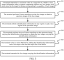
- FIG. 3 is a flowchart of a face image transmission method according to an embodiment of the invention. Referring to FIG. 3 , this embodiment may be applied to the terminal 120 in the foregoing implementation environment. The details are as follows: 301.
- a terminal determines a maximum value in a target list of a buffer as face image information when a camera component acquires any face image, each value stored in the target list being corresponding to a quantity of face images.
- the terminal is configured to perform face image transmission.
- the terminal includes the camera component and may include a host.
- the camera component is configured to acquire a face image and embed label information in the acquired face image.
- the camera component transmits the face image carrying the label information to the host.
- the host transmits the face image carrying the label information to a server.
- the camera component is a 3D camera component, so that the camera component can detect information about distance between each pixel in an acquired image and a camera to determine whether a user corresponding to a currently acquired face image is a living body to prevent attackers from using other people's photos to perform identity verification to steal other people's funds for value transfer.
- the camera component includes a sensor, a processor, a memory, and a battery.
- the memory of the camera component stores a target list.
- the target list includes a plurality of values, and each value is corresponding to a quantity of face images.
- the processor of the camera component writes a new value into the target list and may delete an existing value with the earliest timestamp in the target list, to achieve real-time update of the target list.
- each value in a target list may be equal to the quantity of face images, and the target list is [500, 501, 502, ...].
- each value in a target list may be N times (N>1) the quantity of face images, and the target list is [500N, 501N, 502N, ...].
- each value in a target list may alternatively be a value obtained by exponential transformation or logarithmic transformation of the quantity of face images. A transformation manner between the quantity of face images and each value stored in the target list is not limited in the invention.
- a terminal operating system may deliver an acquisition instruction to the camera component, and the camera component acquires a face image through the sensor of the camera component in response to the acquisition instruction.
- the sensor may acquire a face data stream of a user in real time.
- the sensor transmits the acquired face image to the processor of the camera component.
- the processor determines a target list from a buffer, queries a maximum value in the target list, and determines the maximum value as face image information.
- different types of sensors may acquire different types of face images.
- the face image acquired by an infrared image sensor is an infrared image
- the face image acquired by a depth image sensor is a depth image
- the face image acquired by a color image sensor is a color image.
- Types of the sensor and the face image are not limited in the invention.
- the camera component maintains a target list with a maximum value updated as a quantity of acquired face images increases through the internal processor and memory, when the quantity of acquired face images by the camera component is larger, the maximum value in the target list is larger, resulting in a larger value of the face image information, so that the camera component implements counting of a quantity of all acquired face images based on the face image information.
- the terminal reads the face image information from the buffer, and the face image information is used for indicating a quantity of all face images previously acquired by the camera component.
- the terminal may not store the face image information in the form of a target list, but instead store the face image information in data formats such as stacks, arrays, and tuples.
- the terminal performs Fourier transform on the face image to obtain a spectrum image of the face image.
- the terminal may perform discrete cosine transform (DCT) on the face image to obtain the spectrum image of the face image.
- DCT is a discrete Fourier transform method, which is mainly used to compress data or images to convert signals in a spatial domain to a frequency domain, and has good decorrelation performance.
- the terminal embeds label information in any region except a face region in the spectrum image.
- the label information is used for indicating the face image information.
- the label information may be a value obtained by adding the face image information and a third target value.
- the third target value may be any value greater than or equal to 0.
- the label information may alternatively be a value obtained by multiplying the face image information by a fourth target value.
- the fourth target value may be any value greater than or equal to 1.
- the fourth target value and the third target value may be the same or may be different.
- the label information may alternatively be a value obtained after one-way encryption of the face image information.
- a transformation manner between the face image information and the label information is not limited in the invention.
- any region except the face region may be at least one of an upper left corner, a lower left corner, an upper right corner, or a lower right corner of the face image.
- the any region is determined as the upper left corner of the face image.
- a location of an embedding region of the label information is not limited in the invention.
- the label information is the same as the face image information, and the terminal may embed the face image information in any region except the face region in the spectrum image.
- the terminal may add the face image information determined in the step 301 and the third target value to obtain the label information, and then embed the label information in any region except the face region in the spectrum image.
- the label information is embedded in any region except the face region in the face image, which can prevent pixel information of the face region in the face image from being destroyed to avoid the problem of inability to perform face recognition due to occlusion of the face region, and can optimize the processing logic of the face image transmission process.
- the terminal performs inverse Fourier transform on the spectrum image carrying the label information to obtain the face image carrying the label information.
- the terminal may perform inverse DCT transform on the spectrum image carrying the label information, and convert the spectrum image carrying the label information from the frequency domain back to the spatial domain, so that the user cannot perceive the label information embedded in the face image can be ensured.
- the label information that the user cannot perceive may be commonly referred to as "blind watermark” or "digital watermark".
- blind watermark or "digital watermark”.
- the user can neither see nor hear the blind watermark, but when the terminal transmits the face image carrying the blind watermark to the server, the server can parse out the blind watermark carried in the face image.
- the terminal may embed the label information in any region except the face region in the face image.
- the terminal may alternatively embed the label information in the face region in the face image. Whether the embedding region of the label information is the face region is not limited in the invention.
- the terminal embeds the label information in the face image to obtain the face image carrying the label information.
- the label information is used for indicating the face image information.
- Security precaution can be carried out in a manner of embedding a blind watermark for a face data source (that is, any face image) acquired by the camera component.
- the server can recognize in time that the label information of the previous face image has expired and the previous face image is not the face image acquired in real time at the latest time, so that the verification of the face image is determined to be failed, greatly improving the security of various services of the verification based on the face image.
- the terminal writes a value obtained by adding the label information and a first target value into the target list of the buffer.
- the first target value is a value greater than 0.
- the first target value is 1.
- the terminal may further write the value obtained by adding the label information and the first target value into the target list. Since the face image information is an original maximum value in the target list, the label information is greater than or equal to the face image information, and the value written this time is greater than or equal to the label information, then the value written this time is greater than or equal to the original maximum value in the target list. Therefore, the maximum value in the target list is updated to maintain the maximum value in the target list stored in the memory of the camera component to increase as the quantity of acquired face images increases.
- the sensor of the camera component is SENSOR
- the processor of the camera component is DSP
- the memory of the camera component is FLASH
- each value in the target list stored in the FLASH is FLASH is exactly the quantity of face images.
- the FLASH counts the quantity of acquired face images in real time for updating.
- the DSP obtains the face data stream from the SENSOR, and reads a maximum quantity of face images (that is, the current latest count) from the target list stored in the FLASH for each frame of face image (that is, any image frame in the face data stream).
- the DSP determines a value obtained by adding one to the maximum quantity of face images as label information, and embeds the label information into the frame of face image. In an embodiment not being part of the invention, assuming that a first target value is 0, the DSP directly writes the label information into the target list.
- the current latest count in the target list of the FLASH is 1000, indicating that the quantity of all face images previously acquired by the camera component is 1000.
- the DSP reads the current latest count 1000 from the target list of the FLASH and determines that the label information is 1001.
- the label information 1001 is embedded in the 1001th face image in the form of a blind watermark, and the label information 1001 is then written back to the target list, so that the DSP can read 1001 when reading a current latest count next time, ensuring that the DSP can read an increasing count every time from the FLASH.
- each value in the target list stored in the FLASH is exactly a value obtained by adding one to the quantity of face images
- the current latest count read by the DSP from the target list stored in the FLASH is a value obtained by adding one to a maximum quantity of face images for each frame of face image.
- the DSP determines a value obtained by adding one to the maximum quantity of face images as label information, and embeds the label information into the frame of face image.
- a first target value is 1, the DSP writes a value obtained by adding one to the label information into the target list.
- the current latest count in the target list of the FLASH is 1000, indicating that the quantity of all face images previously acquired by the camera component is 999.
- the DSP reads the current latest count 1000 from the target list of the FLASH and determines that the label information is 1000.
- the label information 1000 is embedded in the 1000th face image in the form of a blind watermark, and a value 1001 obtained by adding one to the label information 1000 is then written back to the target list, so that the DSP can read 1001 when reading a current latest count next time, ensuring that the DSP can read an increasing count every time from the FLASH.
- the terminal may store the face image information in the memory of the camera component not in the form of a target list, but directly store the face image information in a target address, so that the storage space of the memory of the camera component can be saved.
- the step 301 may be replaced by the following step: the terminal determines a value stored in the target address of the buffer as the face image information, that is, the terminal reads the target address in the memory of the camera component through the processor of the camera component, and determines the value stored in the target address as the face image information.
- the step 305 may be replaced by the following step: the terminal sets the value stored in the target address as a value obtained by adding the label information and a second target value, where the second target value is any value greater than or equal to 0.
- the second target value is 1, and the second target value is the same as or different from the first target value.
- the value of the second target value or the first target value is not limited in this embodiment of the invention.
- the terminal does not need to maintain a costly target list in the memory of the camera component, but only stores the quantity of all face images that have been acquired in the target address, which can reduce the resource cost occupied by the memory. Therefore, the face image information stored in the target address can be updated in real time, and the processing efficiency of the camera component can be improved.
- the terminal transmits the face image carrying the label information.
- the terminal may separately transmit the face image carrying the label information, or may encapsulate the face image carrying the label information together with other information into a service request to transmit the service request.
- the service request may correspond to different service types, such as an identity verification service and a value transfer service. Service types of the service request are not limited in the invention.
- the terminal may encapsulate a camera identification of the camera component and the face image carrying the label information into an identity verification request to transmit the identity verification request to the server.
- the terminal may alternatively encapsulate the camera identification of the camera component, the face image carrying the label information, and value transfer information into a value transfer request to transmit the value transfer request to the server.
- the value transfer information includes at least a first user identification, a second user identification, and a value that is to be transferred.
- face image information is read from a buffer.
- the face image information is used for indicating a quantity of all face images previously acquired by the camera component.
- Label information is embedded in the face image to obtain the face image carrying the label information.
- the label information is used for indicating the face image information.
- the face image carrying the label information is transmitted. Therefore, the label information can be directly embedded in the face image acquired by the camera component, improving the security of the face image acquired by the camera component. Even if a face image is leaked, when an attacker steals a previous face image to request related services, the verification cannot be successful due to the discrepancy in the label information, thereby effectively ensuring the security of the face image transmission process.
- the face image transmission method can ensure the security of the face data source acquired by the camera component.
- the unique identification of the acquisition timing of the face image based on the label information can effectively ensure that the face image acquired each time can only be used once.
- Each user does not need to perform hardware upgrade or system transformation on the host of the terminal, and there is no mandatory requirement for the configuration of the host.
- Each user only needs to access the camera component provided by this embodiment of the invention to ensure the security of the face data source, which greatly reduces the difficulty for maintaining the security of the face data source, and has high portability and usability.
- the face image transmission method may be applied to various service scenarios that rely on face images.
- the process of performing identity verification based on a face image to complete a value transfer service is used as an example.
- the process is referred to as a face payment scenario or a facial recognition payment scenario, which is described in detail below.
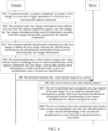
- FIG. 4 is an interaction flowchart of a value transfer method according to an embodiment of the invention. Referring to FIG. 4 , this embodiment is applied to the interaction process between the terminal 120 and the server 140 in the foregoing implementation environment. This embodiment includes the following steps: 401.
- a terminal invokes a camera component to acquire a face image when a trigger operation of a first user on a value transfer option is detected.
- the terminal may be a personal terminal of the first user, or may be a "facial recognition payment terminal" set in a store where a second user is located.
- the facial recognition payment terminal refers to an electronic device that integrates a camera and can acquire a face image of the user and then make a payment. Device types of the terminal are not limited in this embodiment of the invention.
- the first user and the second user are only distinguished names for users with different identities in a certain process of value transfer.
- a certain user may be both a first user and a second user, that is, the user transfers a value from an account to another account both owned by himself/herself.
- a certain user may be as a first user in a value transfer process and as a second user in another value transfer process.
- the first user triggers the terminal to display a payment interface on a display screen.
- the payment interface may include value transfer information and a value transfer option.
- the first user may perform a trigger operation on the value transfer option.
- a terminal operating system delivers an acquisition instruction to the camera component and invokes the camera component to acquire a face image of the first user.
- the value transfer information may include at least a first user identification, a second user identification, and a value that is to be transferred.
- the value transfer information may further include transaction item information, discount information, transaction timestamp, and the like.
- the terminal reads face image information from a buffer when the camera component acquires any face image, the face image information being used for indicating a quantity of all face images previously acquired by the camera component.
- the step 402 is similar to the step 301, and details are not described herein again.
- the terminal embeds label information in the face image to obtain the face image carrying the label information, the label information being used for indicating the face image information.
- the step 403 is similar to the steps 302 to 304. Details are not described herein again.
- the terminal generates a value transfer request, the value transfer request including at least a camera identification of the camera component, the face image carrying the label information, a value that is to be transferred, a first user identification, and a second user identification.
- the terminal may compress the camera identification of the camera component, the face image carrying the label information, the value that is to be transferred, the first user identification, and the second user identification by using a compression algorithm to obtain compressed information, encrypt the compressed information by using an encryption algorithm to obtain ciphertext information, and encapsulate the ciphertext information by using a transmission protocol to obtain the value transfer request.
- the compression algorithm may include at least one of a br compression algorithm, a gzip compression algorithm, or a Huffman compression algorithm
- the encryption algorithm may include at least one of a symmetric encryption algorithm or an asymmetric encryption algorithm, such as a message digest algorithm and a Diffie-Hellman (DH) key exchange algorithm
- the transmission protocol may include at least one of an Internet Protocol (IP), a transmission control protocol (TCP), or a user datagram protocol (UDP).
- IP Internet Protocol
- TCP transmission control protocol
- UDP user datagram protocol
- the terminal transmits the value transfer request to a server.
- the server may perform identity verification based on the camera identification of the camera component and the face image carrying the label information.
- the value that is to be transferred is transferred from a value stored corresponding to the first user identification to a value stored corresponding to the second user identification when the verification is successful.
- the implementation process is described in detail in the following steps 406 to 408.
- the server receives the value transfer request.
- the value transfer request includes at least a camera identification, a face image carrying label information, a value that is to be transferred, a first user identification, and a second user identification, the label information being used for indicating that the face image is an image acquired in real time.
- the server may parse the value transfer request to obtain ciphertext information, decrypt the ciphertext information by using a decryption algorithm to obtain compressed information, and decompress the compressed information to obtain the camera identification, the face image carrying the label information, the value that is to be transferred, the first user identification, and the second user identification.
- the decryption algorithm and decompression algorithm used herein respectively correspond to the encryption algorithm and compression algorithm in the step 404, and details are not described herein.
- the server performs face recognition on a face region of the face image when the label information is greater than each previous label information stored corresponding to the camera identification to obtain a recognition result.
- the server stores label information of each face image corresponding to each camera identification.
- the server may maintain an label information sequence corresponding to each camera identification in a backend, and store each previous label information of face images corresponding to the same camera identification in the same sequence, so that when any value transfer request carrying the camera identification is received, a face image carrying the label information in the value transfer request is obtained, and the label information is extracted from the face image.
- the server may query a maximum previous value in the label information sequence corresponding to the camera identification. If the extracted label information is greater than the maximum previous value, it is determined that the face image is valid, that is, the face image is not a stolen previous face image, and the server performs face recognition on a face region of the face image to obtain a recognition result. Otherwise, if the extracted label information is less than or equal to the maximum previous value, it is determined that the face image is invalid, that is, the face image is a stolen previous face image, and the server may transmit verification failure information to the terminal.
- the face image in the process of face recognition, may be inputted to a face similarity model, and a similarity between the face image and a pre-stored image of a first user may be predicted by using the face similarity model. If the similarity is greater than or equal to a target threshold, it is determined that the recognition result of the face image is successful, and the following step 408 is performed. Otherwise, if the similarity is less than the target threshold, it is determined that the recognition result of the face image is not successful, and the server may transmit verification failure information to the terminal.
- the server transfers the value that is to be transferred from a value stored corresponding to the first user identification to a value stored corresponding to the second user identification when the recognition result is successful.
- the server performs the operation of transferring the value that is to be transferred from a value stored corresponding to the first user identification to a value stored corresponding to the second user identification, so that the first user completes the transfer of the value that is to be transferred to the second user.
- the server performs value transfer based on the camera identification of the camera component and the face image carrying the label information.
- the server may further transmit transfer success information to the terminal to notify the terminal that the value transfer operation has been successfully performed.
- a terminal invokes a camera component to acquire a face image.
- face image information is read from a buffer.
- the face image information is used for indicating a quantity of all face images previously acquired by the camera component.
- Label information is embedded in the face image to obtain the face image carrying the label information.
- the label information is used for indicating the face image information.
- Value transfer is performed based on a camera identification of the camera component and the face image carrying the label information. Therefore, in the process of value transfer, the label information is directly embedded in the face image acquired by the camera component, improving the security of the face image acquired by the camera component. Even if a face image is leaked, when an attacker steals a previous face image to request a value transfer service, the verification cannot be successful due to the discrepancy in the label information, thereby effectively ensuring the security of the value transfer process.
- the server receives a value transfer request.
- the value transfer request includes at least a camera identification, a face image carrying label information, a value that is to be transferred, a first user identification, and a second user identification.
- the label information is used for indicating that the face image is an image acquired in real time.
- face recognition is performed on a face region of the face image to obtain a recognition result.
- the recognition result is successful, the value that is to be transferred is transferred from a value stored corresponding to the first user identification to a value stored corresponding to the second user identification.
- the server can determine whether the face image carrying the label information is a stolen previous face image by comparing the label information with each stored previous label information, which obtains a way to verify the face image in a time dimension, and can deal with more complex network attacks. Even if a face image is leaked, when an attacker steals a previous face image to request a value transfer service, the verification cannot be successful due to the discrepancy in the label information, thereby effectively ensuring the security of the value transfer process.
- FIG. 5 is a schematic principle diagram of a value transfer method according to the invention.
- the internal improvement of a camera component of a facial recognition payment terminal can add a security precaution to the camera component that acquires a face data source without the need to perform hardware upgrade on the host side, which strictly ensures the security of the face data source and can effectively resist the "replay attack" of the face data.
- the camera component of the terminal stores face image information in the FLASH
- the DSP may read a face image count (that is, the face image information) from the FLASH and embed a blind watermark (that is, label information) on each frame of face image in the face data stream.
- the blind watermark is used for indicating the face image count.
- the DSP transmits the face image carrying the blind watermark to the host.
- the host transmits the face image carrying the blind watermark to the server.
- the server stores an increasing sequence corresponding to a camera identification of the camera component in the backend. Each previous blind watermark (that is, a previous face image count) in the increasing sequence increases with time.
- the face image transmitted this time is valid. Otherwise, it is considered that the face image transmitted this time is invalid. Therefore, the validity of the sequence is verified through the foregoing process, which ensures the security of the face image transmission process, and avoids the "replay attack" of the face image. Further, when it is determined that the face image transmitted this time is valid, the face recognition is performed on the face image, and when the recognition result of the face recognition is successful, the value transfer operation is performed, thereby ensuring the security of the value transfer process.
- FIG. 6 is a schematic structural diagram of a face image transmission apparatus according to an embodiment not being part of the invention.
- the apparatus includes:
- face image information is read from a buffer.
- the face image information is used for indicating a quantity of all face images previously acquired by the camera component.
- Label information is embedded in the face image to obtain the face image carrying the label information.
- the label information is used for indicating the face image information.
- the face image carrying the label information is transmitted. Therefore, the label information can be directly embedded in the face image acquired by the camera component, improving the security of the face image acquired by the camera component. Even if a face image is leaked, when an attacker steals a previous face image to request related services, the verification cannot be successful due to the discrepancy in the label information, thereby effectively ensuring the security of the face image transmission process.
- the reading module 601 is configured to: determine a maximum value in a target list of the buffer as the face image information, each value stored in the target list being corresponding to a quantity of face images.
- the apparatus is further configured to: write a value obtained by adding the label information and a first target value into the target list of the buffer.
- the reading module 601 is configured to: determine a value stored in a target address of the buffer as the face image information.
- the apparatus is further configured to: set the value stored in the target address as a value obtained by adding the label information and a second target value.
- the label information is a value obtained by adding the face image information and a third target value.
- the embedding module 602 is configured to: embed the label information in any region except a face region in the face image.
- the embedding module 602 is configured to:
- the face image transmission apparatus When the face image transmission apparatus provided in the invention transmits a face image, it is illustrated with an example of division of each functional module.
- the function distribution may be implemented by different functional modules according to requirements, that is, an internal structure of an electronic device (for example, a terminal) is divided into different functional modules, to implement all or some of the functions described above.
- the face image transmission apparatus and the face image transmission method embodiments provided in the foregoing embodiments belong to the same conception. For the implementation process, reference may be made to the face image transmission method embodiment, and details are not described herein again.
- FIG. 7 is a schematic structural diagram of a value transfer apparatus according to an embodiment not being part of the invention.
- the apparatus includes:
- a terminal invokes a camera component to acquire a face image.
- face image information is read from a buffer.
- the face image information is used for indicating a quantity of all face images previously acquired by the camera component.
- Label information is embedded in the face image to obtain the face image carrying the label information.
- the label information is used for indicating the face image information.
- Value transfer is performed based on a camera identification of the camera component and the face image carrying the label information. Therefore, in the process of value transfer, the label information is directly embedded in the face image acquired by the camera component, improving the security of the face image acquired by the camera component. Even if a face image is leaked, when an attacker steals a previous face image to request a value transfer service, the verification cannot be successful due to the discrepancy in the label information, thereby effectively ensuring the security of the value transfer process.
- the value transfer module 704 is configured to:
- the value transfer apparatus transfers a value provided in the invention
- it is illustrated with an example of division of each functional module.
- the function distribution may be finished by different functional modules according to the requirements, that is, the internal structure of an electronic device (for example, a terminal) is divided into different functional modules, to implement all or some of the functions described above.
- the value transfer apparatus and value transfer method embodiments provided in the foregoing embodiments belong to the same conception. For the implementation process, reference may be made to the value transfer method embodiment, and details are not described herein again.
- FIG. 8 is a schematic structural diagram of a value transfer apparatus according to an embodiment not being part of the invention.
- the apparatus includes:
- a value transfer request is received.
- the value transfer request includes at least a camera identification, a face image carrying label information, a value that is to be transferred, a first user identification, and a second user identification.
- the label information is used for indicating that the face image is an image acquired in real time.
- face recognition is performed on a face region of the face image to obtain a recognition result.
- the recognition result is successful, the value that is to be transferred is transferred from a value stored corresponding to the first user identification to a value stored corresponding to the second user identification.
- Whether the face image carrying the label information is a stolen previous face image can be determined by comparing the label information with each stored previous label information, which obtains a way to verify the face image in a time dimension, and can deal with more complex network attacks. Even if a face image is leaked, when an attacker steals a previous face image to request a value transfer service, the verification cannot be successful due to the discrepancy in the label information, thereby effectively ensuring the security of the value transfer process.
- the value transfer apparatus transfers a value provided in the invention
- it is illustrated with an example of division of each functional module.
- the function distribution may be finished by different functional modules according to the requirements, that is, the internal structure of an electronic device (for example, a server) is divided into different functional modules, to implement all or some of the functions described above.
- the value transfer apparatus and value transfer method embodiments provided in the foregoing embodiments belong to the same conception. For the implementation process, reference may be made to the value transfer method embodiment, and details are not described herein again.
- FIG. 9 is a structural block diagram of a terminal 900 according to an embodiment of the invention.
- the terminal 900 is also an electronic device.
- the terminal 900 is a smartphone, a tablet computer, an MP3 player, an MP4 player, a notebook computer, or a desktop computer.
- the terminal 900 may also be referred to as a user equipment, a portable terminal, a laptop terminal, a desktop terminal, or the like.
- the terminal 900 includes a processor 901 and a memory 902.
- the processor 901 may include one or more processing cores, for example, a 4-core processor or an 8-core processor.
- the processor 901 may be implemented in at least one hardware form of DSP, FPGA, and PLA.
- the processor 901 may also include a main processor and a coprocessor.
- the main processor is a processor configured to process data in an awake state, and is also referred to as a central processing unit (CPU).
- the coprocessor is a low power consumption processor configured to process data in a standby state.
- the processor 901 may be integrated with a graphics processing unit (GPU).
- the GPU is configured to be responsible for rendering and drawing content that a display needs to display.
- the processor 901 may include an AI processor.
- the AI processor is configured to process a computing operation related to machine learning.
- the memory 902 may include one or more computer-readable storage media that may be non-transitory.
- the memory 902 may further include a high-speed random access memory and a non-volatile memory, such as one or more magnetic disk storage devices or a flash storage device.
- the non-transient computer-readable storage medium in the memory 902 is configured to store at least one instruction, and the at least one instruction is used to be executed by the processor 901 to implement the following operations:
- the at least one instruction is used to be executed by the processor 901 to implement the following operations: determining a maximum value in a target list of the buffer as the face image information, each value stored in the target list being corresponding to a quantity of face images.
- the at least one instruction is used to be executed by the processor 901 to implement the following operations: writing a value obtained by adding the label information and a first target value into the target list of the buffer.
- the at least one instruction is used to be executed by the processor 901 to implement the following operations: determining a value stored in a target address of the buffer as the face image information.
- the at least one instruction is used to be executed by the processor 901 to implement the following operations: setting the value stored in the target address as a value obtained by adding the label information and a second target value.
- the label information is a value obtained by adding the face image information and a third target value.
- the at least one instruction is used to be executed by the processor 901 to implement the following operations: embedding the label information in any region except a face region in the face image.
- the at least one instruction is used to be executed by the processor 901 to implement the following operations:
- the at least one instruction is used to be executed by the processor 901 to implement the following operations:
- the at least one instruction is used to be executed by the processor 901 to implement the following operations:
- the terminal 900 may further include: a peripheral interface 903 and at least one peripheral.
- the processor 901, the memory 902, and the peripheral interface 903 may be connected by a bus or a signal cable.
- Each peripheral may be connected to the peripheral interface 903 by a bus, a signal cable, or a circuit board.
- the peripheral includes: at least one of a radio frequency (RF) circuit 904, a touch display screen 905, a camera component 906, an audio circuit 907, a positioning component 908, and a power supply 909.
- RF radio frequency
- the peripheral interface 903 may be configured to connect the at least one peripheral related to Input/Output (I/O) to the processor 901 and the memory 902.
- the processor 901, the memory 902, and the peripheral interface 903 may be integrated on the same chip or circuit board. Any one or two of the processor 901, the memory 902, and the peripheral interface 903 may be implemented on an independent chip or circuit board. This is not limited in the invention.
- the RF circuit 904 is configured to receive and transmit an RF signal, which is also referred to as an electromagnetic signal.
- the RF circuit 904 communicates with a communication network and other communication devices through the electromagnetic signal.
- the RF circuit 904 converts an electrical signal into an electromagnetic signal for transmission, or converts a received electromagnetic signal into an electrical signal.
- the RF circuit 904 may include: an antenna system, an RF transceiver, one or more amplifiers, a tuner, an oscillator, a digital signal processor, a codec chip set, a subscriber identity module card, and the like.
- the RF circuit 904 may communicate with another terminal through at least one wireless communication protocol.
- the wireless communication protocol includes, but is not limited to: a metropolitan area network, generations of mobile communication networks (2G, 3G, 4G, and 5G), a wireless local area network and/or a wireless fidelity (Wi-Fi) network.
- the RF circuit 904 may further include a circuit related to near field communication (NFC). This is not limited in the invention.
- the display screen 905 is configured to display a user interface (UI).
- the UI may include a graph, a text, an icon, a video, and any combination thereof.
- the display screen 905 is further capable of collecting touch signals on or above a surface of the display screen 905.
- the touch signal may be inputted to the processor 901 for processing as a control signal.
- the display screen 905 may be further configured to provide a virtual button and/or a virtual keyboard that are/is also referred to as a soft button and/or a soft keyboard.
- the display screen 905 is a flexible display screen, disposed on a curved surface or a folded surface of the terminal 900. Even, the display screen 905 may be further set to have a non-rectangular irregular pattern, that is, a special-shaped screen.
- the display screen 905 may be prepared by using materials such as a liquid crystal display (LCD), an organic light-emitting diode (OLED), or the like.
- the camera component 906 is configured to acquire images or videos.
- the camera component 906 may include a front-facing camera and a rear-facing camera.
- the front-facing camera is disposed on a front panel of the terminal
- the rear-facing camera is disposed on a rear surface of the terminal.
- the camera component 906 may further include a flash.
- the flash may be a single color temperature flash or a double color temperature flash.
- the double color temperature flash is a combination of a warm light flash and a cold light flash, and may be used for light compensation under different color temperatures.
- the audio circuit 907 includes a microphone and a speaker.
- the microphone is configured to collect sound waves of users and surroundings, and convert the sound waves into electrical signals and input the signals to the processor 901 for processing, or input the signals to the RF circuit 904 to implement voice communication.
- the microphone is an array microphone or an omni-directional acquisition microphone.
- the speaker is configured to convert electrical signals from the processor 901 or the RF circuit 904 into sound waves.
- the speaker may be a conventional thin-film speaker, or may be a piezoelectric ceramic speaker.
- the speaker When the speaker is the piezoelectric ceramic speaker, the speaker can not only convert an electrical signal into sound waves audible to a human being, but also convert an electrical signal into sound waves inaudible to the human being for ranging and other purposes.
- the audio circuit 907 may also include an earphone jack.
- the positioning component 908 is configured to determine a current geographic location of the terminal 900, to implement navigation or a location based service (LBS).
- the positioning component 908 may be a positioning component based on the Global Positioning System (GPS) of the United States, the BeiDou system of China, the GLONASS System of Russia, or the GALILEO System of the European Union.
- GPS Global Positioning System
- the power supply 909 is configured to supply power to components in the terminal 900.
- the power supply 909 may be an alternating-current power supply, a direct-current power supply, a disposable battery, or a rechargeable battery.
- the rechargeable battery may support wired charging or wireless charging.
- the rechargeable battery may further be configured to support a quick charge technology.
- the terminal 900 further includes one or more sensors 910.
- the one or more sensors 910 include, but are not limited to, an acceleration sensor 911, a gyroscope sensor 912, a pressure sensor 913, a fingerprint sensor 914, an optical sensor 915, and a proximity sensor 916.
- the acceleration sensor 911 may detect the magnitude of acceleration on three coordinate axes of a coordinate system established by the terminal 900.
- the acceleration sensor 911 may be configured to detect components of the gravity acceleration on the three coordinate axes.
- the processor 901 may control, according to a gravity acceleration signal collected by the acceleration sensor 911, the touch display screen 905 to display the UI in a landscape view or a portrait view.
- the acceleration sensor 911 may be further configured to acquire motion data of a game or a user.
- the gyroscope sensor 912 may detect a body direction and a rotation angle of the terminal 900, and may work with the acceleration sensor 911 to acquire a 3D action performed by the user on the terminal 900.
- the processor 901 may implement the following functions according to data collected by the gyroscope sensor 912: motion sensing (for example, the UI is changed according to a tilt operation of the user), image stabilization during shooting, game control, and inertial navigation.
- the pressure sensor 913 may be disposed on a side frame of the terminal 900 and/or a lower layer of the touch display screen 905.
- a holding signal of the user to the terminal 900 may be detected, and left/right hand identification or a quick action may be performed by the processor 901 according to the holding signal acquired by the pressure sensor 913.
- the processor 901 controls, according to a pressure operation of the user on the touch display screen 905, an operable control on the UI.
- the operable control includes at least one of a button control, a scroll-bar control, an icon control, and a menu control.
- the fingerprint sensor 914 is configured to collect a fingerprint of the user, and the processor 901 recognizes an identity of the user according to the fingerprint collected by the fingerprint sensor 914, or the fingerprint sensor 914 recognizes the identity of the user according to the collected fingerprint.
- the processor 901 authorizes the user to perform a related sensitive operation.
- the sensitive operation includes unlocking a screen, viewing encrypted information, downloading software, paying, changing a setting, and the like.
- the fingerprint sensor 914 may be disposed on a front surface, a back surface, or a side surface of the terminal 900. When a physical button or a vendor logo is disposed on the terminal 900, the fingerprint sensor 914 may be integrated with the physical button or the vendor logo.
- the optical sensor 915 is configured to acquire ambient light intensity.
- the processor 901 may control display brightness of the touch display screen 905 according to the ambient light intensity acquired by the optical sensor 915.
- the processor 901 may further dynamically adjust a camera parameter of the camera component 906 according to the ambient light intensity acquired by the optical sensor 915.
- the proximity sensor 916 also referred to as a distance sensor, is generally disposed on the front panel of the terminal 900.
- the proximity sensor 916 is configured to collect a distance between the user and the front face of the terminal 900.
- the touch display screen 905 may be controlled by the processor 901 to switch from a screen-on state to a screen-off state; and when the proximity sensor 916 detects that the distance between the user and the front surface of the terminal 900 gradually becomes larger, the touch display screen 905 may be controlled by the processor 901 to switch from the screen-off state to the screen-on state.
- FIG. 9 does not constitute a limitation to the terminal 900, and the terminal may include more or fewer components than those shown in the figure, or some components may be combined, or a different component arrangement may be used.
- FIG. 10 is a schematic structural diagram of a server according to an embodiment of the invention.
- a server 1000 is also an electronic device.
- the server 1000 may vary greatly because a configuration or performance varies, and may include one or more processors (CPU) 1001 and one or more memories 1002.
- the memory 1002 stores at least one program code, and the at least one program code is loaded and executed by the processor 1001 to implement the following operations:
- the value transfer request including at least a camera identification, a face image carrying label information, a value that is to be transferred, a first user identification, and a second user identification, the label information being used for indicating that the face image is an image acquired in real time;
- the server 1000 may also have a wired or wireless network interface, a keyboard, an input/output interface and other components to facilitate input/output.
- the server 1000 may also include other components for implementing device functions. Details are not described herein.
- a computer-readable storage medium for example, a memory including at least one program code is further provided.
- the at least one program code may be executed by a processor in a terminal to implement the following operations:
- the at least one program code may be executed by a processor in a terminal to implement the following operations: determining a maximum value in a target list of the buffer as the face image information, each value stored in the target list being corresponding to a quantity of face images.
- the at least one program code may be executed by a processor in a terminal to implement the following operations: writing a value obtained by adding the label information and a first target value into the target list of the buffer.
- the at least one program code may be executed by a processor in a terminal to implement the following operations: determining a value stored in a target address of the buffer as the face image information.
- the at least one program code may be executed by a processor in a terminal to implement the following operations: setting the value stored in the target address as a value obtained by adding the label information and a second target value.
- the label information is a value obtained by adding the face image information and a third target value.
- the at least one program code may be executed by a processor in a terminal to implement the following operations: embedding the label information in any region except a face region in the face image.
- the at least one program code may be executed by a processor in a terminal to implement the following operations:
- the computer-readable storage medium is a read-only memory (ROM), a random-access memory (RAM), a compact disc read-only memory (CD-ROM), a magnetic tape, a floppy disk, an optical data storage device, or the like.
- a computer program or computer program product including at least one program code is further provided, the computer program or computer program product, when run on a computer device, causing the computer device to perform any possible implementation in the face image transmission method or the value transfer method provided in the foregoing embodiments. Details are not described herein.
- the program may be stored in a computer-readable storage medium.
- the storage medium may be: a ROM, a magnetic disk, or an optical disc.
Landscapes
- Engineering & Computer Science (AREA)
- Theoretical Computer Science (AREA)
- Physics & Mathematics (AREA)
- General Physics & Mathematics (AREA)
- Multimedia (AREA)
- Health & Medical Sciences (AREA)
- General Health & Medical Sciences (AREA)
- Signal Processing (AREA)
- Human Computer Interaction (AREA)
- Computer Security & Cryptography (AREA)
- Oral & Maxillofacial Surgery (AREA)
- Business, Economics & Management (AREA)
- Computer Hardware Design (AREA)
- General Engineering & Computer Science (AREA)
- Software Systems (AREA)
- Accounting & Taxation (AREA)
- Computer Networks & Wireless Communication (AREA)
- Computing Systems (AREA)
- Biomedical Technology (AREA)
- Finance (AREA)
- Strategic Management (AREA)
- General Business, Economics & Management (AREA)
- Computer Vision & Pattern Recognition (AREA)
- Marketing (AREA)
- Technology Law (AREA)
- Economics (AREA)
- Bioethics (AREA)
- Development Economics (AREA)
- Image Processing (AREA)
- Financial Or Insurance-Related Operations Such As Payment And Settlement (AREA)
Claims (2)
- Ein Verfahren zur Senden von Gesichtsbilddaten, umfassend:Lesen, durch ein Endgerät, von Gesichtsbildinformationen aus einem Puffer der Kamerakomponente, wenn die Kamerakomponente des Endgeräts ein beliebiges Gesichtsbild erfasst, wobei die Gesichtsbildinformationen eine Menge aller zuvor von der Kamerakomponente erfassten Gesichtsbilder angeben;Einbetten, durch das Endgerät, von Identifikationsinformationen in Form eines Wasserzeichens in das Gesichtsbild, um das Gesichtsbild mit den Identifikationsinformationen zu erhalten, wobei die Identifikationsinformationen die Gesichtsbildinformationen angeben;Senden, durch das Endgerät, des Gesichtsbilds mit den Identifikationsinformationen an einen Remote-Server zur Authentifizierung des Gesichtsbilds mithilfe der Identifikationsinformationen, wobei der Remote-Server bestimmt, ob es sich bei dem Gesichtsbild mit den Identifikationsinformationen um ein gestohlenes vorheriges Gesichtsbild handelt, indem er die Identifikationsinformationen mit jeder gespeicherten vorherigen Identifikationsinformation vergleicht;wobei der Puffer der Kamerakomponente eine Zielliste umfasst, die eine Vielzahl von Werten enthält, von denen jeder Wert einer jeweiligen Menge von Gesichtsbildern entspricht, wobei ein Maximalwert in der Zielliste aktualisiert wird, wenn die Menge aller zuvor von der Kamerakomponente erfassten Gesichtsbilder zunimmt, und das Lesen der Gesichtsbildinformationen aus dem Puffer umfasst:Bestimmen der Zielliste aus dem Puffer, Abfragen des Maximalwerts in der Zielliste und Bestimmen (301) des Maximalwerts als die Gesichtsbildinformationen;wobei nach dem Einbetten der Identifikationsinformationen in das Gesichtsbild, um das Gesichtsbild mit den Identifikationsinformationen zu erhalten, das Verfahren ferner umfasst:Schreiben (305), durch das Endgerät, eines Wertes, der durch Hinzufügen der Identifikationsinformationen und eines ersten Zielwerts erhalten wird, in die Zielliste des Puffers, um den Maximalwert in der Zielliste zu aktualisieren, wobei der erste Zielwert größer oder gleich 0 ist;gekennzeichnet dadurch, dass die Kamerakomponente einen Sensor, bezeichnet als SENSOR, einen Prozessor, bezeichnet als DSP, und einen Speicher, bezeichnet als FLASH, umfasst;jeder Wert in der im FLASH gespeicherten Zielliste die Menge der Gesichtsbilder darstellt, wobei der FLASH die Menge der erfassten Gesichtsbilder in Echtzeit zur Aktualisierung zählt,der DSP einen Gesichts-Datenstrom vom SENSOR erhält und eine maximale Menge an Gesichtsbildern liest, die ein aktueller letzter Zählerstand aus der im FLASH gespeicherten Zielliste ist,der DSP die Identifikationsinformationen durch Hinzufügen eines dritten Zielwerts zu den Gesichtsbildinformationen bestimmt, wobei der DSP, wenn der dritte Zielwert 1 ist, einen Wert bestimmt, der durch Hinzufügen von 1 zur maximalen Menge an Gesichtsbildern erhalten wird, und der DSP die Identifikationsinformationen in das Gesichtsbild einbettet; und wenn der erste Zielwert 0 ist, der DSP die Identifikationsinformationen in die Zielliste schreibt.
- Ein System, das ein Endgerät in Kommunikation mit einem Remote-Server umfasst, wobei das System so konfiguriert ist, das Verfahren gemäß Anspruch 1 auszuführen.
Applications Claiming Priority (2)
| Application Number | Priority Date | Filing Date | Title |
|---|---|---|---|
| CN201911300268.6A CN111062323B (zh) | 2019-12-16 | 2019-12-16 | 人脸图像传输方法、数值转移方法、装置及电子设备 |
| PCT/CN2020/120316 WO2021120794A1 (zh) | 2019-12-16 | 2020-10-12 | 人脸图像传输方法、数值转移方法、装置及电子设备 |
Publications (3)
| Publication Number | Publication Date |
|---|---|
| EP3989113A1 EP3989113A1 (de) | 2022-04-27 |
| EP3989113A4 EP3989113A4 (de) | 2023-01-18 |
| EP3989113B1 true EP3989113B1 (de) | 2025-01-15 |
Family
ID=70301845
Family Applications (1)
| Application Number | Title | Priority Date | Filing Date |
|---|---|---|---|
| EP20903189.7A Active EP3989113B1 (de) | 2019-12-16 | 2020-10-12 | Gesichtsbildübertragungsverfahren, verfahren und einrichtung zur übertragung numerischer werte und elektronische vorrichtung |
Country Status (5)
| Country | Link |
|---|---|
| US (2) | US12165432B2 (de) |
| EP (1) | EP3989113B1 (de) |
| JP (1) | JP7389236B2 (de) |
| CN (1) | CN111062323B (de) |
| WO (1) | WO2021120794A1 (de) |
Families Citing this family (6)
| Publication number | Priority date | Publication date | Assignee | Title |
|---|---|---|---|---|
| CN111062323B (zh) * | 2019-12-16 | 2023-06-02 | 腾讯科技(深圳)有限公司 | 人脸图像传输方法、数值转移方法、装置及电子设备 |
| CN111046365B (zh) * | 2019-12-16 | 2023-05-05 | 腾讯科技(深圳)有限公司 | 人脸图像传输方法、数值转移方法、装置及电子设备 |
| CN113516723B (zh) * | 2020-11-19 | 2025-09-12 | 腾讯科技(深圳)有限公司 | 人脸图片加密方法、装置、计算机设备及存储介质 |
| CN113450121B (zh) * | 2021-06-30 | 2022-08-05 | 湖南校智付网络科技有限公司 | 用于校园支付的人脸识别方法 |
| CN115205952B (zh) * | 2022-09-16 | 2022-11-25 | 深圳市企鹅网络科技有限公司 | 一种基于深度学习的线上学习图像采集方法及系统 |
| CN119150268B (zh) * | 2024-08-22 | 2026-04-24 | 蚂蚁区块链科技(上海)有限公司 | 攻击防御及检测方法、系统、设备、存储介质及程序产品 |
Citations (1)
| Publication number | Priority date | Publication date | Assignee | Title |
|---|---|---|---|---|
| US20160261911A1 (en) * | 2015-03-02 | 2016-09-08 | The Nielsen Company (Us), Llc | Methods and apparatus to count people |
Family Cites Families (37)
| Publication number | Priority date | Publication date | Assignee | Title |
|---|---|---|---|---|
| US6212285B1 (en) * | 1998-04-15 | 2001-04-03 | Massachusetts Institute Of Technology | Method and apparatus for multi-bit zoned data hiding in printed images |
| US7756892B2 (en) * | 2000-05-02 | 2010-07-13 | Digimarc Corporation | Using embedded data with file sharing |
| US6608911B2 (en) * | 2000-12-21 | 2003-08-19 | Digimarc Corporation | Digitally watermaking holograms for use with smart cards |
| JP2001052143A (ja) | 1999-08-09 | 2001-02-23 | Mega Chips Corp | 認証用記録媒体および認証システム |
| JP2001094755A (ja) | 1999-09-20 | 2001-04-06 | Toshiba Corp | 画像処理方法 |
| US7663670B1 (en) * | 2001-02-09 | 2010-02-16 | Digital Imaging Systems Gmbh | Methods and systems for embedding camera information in images |
| JP4541632B2 (ja) * | 2002-05-13 | 2010-09-08 | パナソニック株式会社 | 電子透かし埋め込み装置、その方法及び記録媒体 |
| US6782116B1 (en) * | 2002-11-04 | 2004-08-24 | Mediasec Technologies, Gmbh | Apparatus and methods for improving detection of watermarks in content that has undergone a lossy transformation |
| US8509472B2 (en) * | 2004-06-24 | 2013-08-13 | Digimarc Corporation | Digital watermarking methods, programs and apparatus |
| JP4799854B2 (ja) * | 2004-12-09 | 2011-10-26 | ソニー株式会社 | 情報処理装置および方法、並びにプログラム |
| US7370190B2 (en) * | 2005-03-03 | 2008-05-06 | Digimarc Corporation | Data processing systems and methods with enhanced bios functionality |
| JP2007116506A (ja) | 2005-10-21 | 2007-05-10 | Fujifilm Corp | 電子申請用顔画像媒体、その作成装置、無効化装置及び再発行装置 |
| US7861056B2 (en) * | 2007-01-03 | 2010-12-28 | Tekelec | Methods, systems, and computer program products for providing memory management with constant defragmentation time |
| US8233677B2 (en) * | 2007-07-04 | 2012-07-31 | Sanyo Electric Co., Ltd. | Image sensing apparatus and image file data structure |
| US8289562B2 (en) * | 2007-09-21 | 2012-10-16 | Fujifilm Corporation | Image processing apparatus, method and recording medium |
| JP5071471B2 (ja) * | 2009-12-18 | 2012-11-14 | コニカミノルタビジネステクノロジーズ株式会社 | 画像形成装置、画像形成方法および画像形成装置を制御する制御プログラム |
| CN101777212A (zh) * | 2010-02-05 | 2010-07-14 | 广州广电运通金融电子股份有限公司 | 安全卡、卡认证系统、具有该系统的金融设备及认证方法 |
| US9626273B2 (en) * | 2011-11-09 | 2017-04-18 | Nec Corporation | Analysis system including analysis engines executing predetermined analysis and analysis executing part controlling operation of analysis engines and causing analysis engines to execute analysis |
| CN104429075B (zh) * | 2012-07-09 | 2017-10-31 | 太阳专利托管公司 | 图像编码方法、图像解码方法、图像编码装置及图像解码装置 |
| KR102106539B1 (ko) * | 2013-07-01 | 2020-05-28 | 삼성전자주식회사 | 화상 통화동안 비디오 컨텐츠를 인증하는 방법 및 디바이스 |
| US9892478B2 (en) * | 2015-03-06 | 2018-02-13 | Digimarc Corporation | Digital watermarking applications |
| AU2017280088A1 (en) * | 2016-06-22 | 2019-05-02 | Southern Star Corporation Pty Ltd | System and methods for delivery of audio and video content |
| CN106485201B (zh) * | 2016-09-09 | 2019-06-28 | 首都师范大学 | 超复数加密域的彩色人脸识别方法 |
| CN106803289A (zh) * | 2016-12-22 | 2017-06-06 | 五邑大学 | 一种智能移动防伪签到方法与系统 |
| CN106920111B (zh) * | 2017-02-23 | 2018-06-26 | 彭雨妍 | 产品生产过程信息的处理方法及系统 |
| US10262191B2 (en) * | 2017-03-08 | 2019-04-16 | Morphotrust Usa, Llc | System and method for manufacturing and inspecting identification documents |
| CN107066983B (zh) * | 2017-04-20 | 2022-08-09 | 腾讯科技(上海)有限公司 | 一种身份验证方法及装置 |
| JP7003136B2 (ja) | 2017-08-02 | 2022-01-20 | マクセル株式会社 | レジシステム |
| CN107679861B (zh) * | 2017-08-30 | 2022-11-11 | 创新先进技术有限公司 | 资源转移方法、资金支付方法、装置及电子设备 |
| JP6946175B2 (ja) * | 2017-12-27 | 2021-10-06 | 富士フイルム株式会社 | 撮影制御システム、撮影制御方法、プログラムおよび記録媒体 |
| US11176373B1 (en) * | 2018-01-12 | 2021-11-16 | Amazon Technologies, Inc. | System and method for visitor detection algorithm |
| CN108306886B (zh) * | 2018-02-01 | 2021-02-02 | 深圳市腾讯计算机系统有限公司 | 一种身份验证方法、装置及存储介质 |
| US10991064B1 (en) * | 2018-03-07 | 2021-04-27 | Adventure Soup Inc. | System and method of applying watermark in a digital image |
| CN114780934B (zh) * | 2018-08-13 | 2025-03-21 | 创新先进技术有限公司 | 一种身份验证方法及装置 |
| CN110086954B (zh) * | 2019-03-26 | 2020-07-28 | 同济大学 | 一种基于数字水印的航线加密方法和执行方法 |
| CN110287841B (zh) * | 2019-06-17 | 2021-09-17 | 秒针信息技术有限公司 | 图像传输方法及装置、图像传输系统、存储介质 |
| CN111062323B (zh) * | 2019-12-16 | 2023-06-02 | 腾讯科技(深圳)有限公司 | 人脸图像传输方法、数值转移方法、装置及电子设备 |
-
2019
- 2019-12-16 CN CN201911300268.6A patent/CN111062323B/zh active Active
-
2020
- 2020-10-12 EP EP20903189.7A patent/EP3989113B1/de active Active
- 2020-10-12 WO PCT/CN2020/120316 patent/WO2021120794A1/zh not_active Ceased
- 2020-10-12 JP JP2022515017A patent/JP7389236B2/ja active Active
-
2021
- 2021-11-16 US US17/528,079 patent/US12165432B2/en active Active
-
2024
- 2024-11-01 US US18/935,309 patent/US20250061744A1/en active Pending
Patent Citations (1)
| Publication number | Priority date | Publication date | Assignee | Title |
|---|---|---|---|---|
| US20160261911A1 (en) * | 2015-03-02 | 2016-09-08 | The Nielsen Company (Us), Llc | Methods and apparatus to count people |
Also Published As
| Publication number | Publication date |
|---|---|
| EP3989113A1 (de) | 2022-04-27 |
| US20250061744A1 (en) | 2025-02-20 |
| JP7389236B2 (ja) | 2023-11-29 |
| US20220075998A1 (en) | 2022-03-10 |
| EP3989113A4 (de) | 2023-01-18 |
| JP2022547923A (ja) | 2022-11-16 |
| CN111062323B (zh) | 2023-06-02 |
| CN111062323A (zh) | 2020-04-24 |
| US12165432B2 (en) | 2024-12-10 |
| WO2021120794A1 (zh) | 2021-06-24 |
Similar Documents
| Publication | Publication Date | Title |
|---|---|---|
| US11783630B2 (en) | Method for transmitting face image data, transferring value, apparatus, and electronic device | |
| EP3989113B1 (de) | Gesichtsbildübertragungsverfahren, verfahren und einrichtung zur übertragung numerischer werte und elektronische vorrichtung | |
| CN110674022B (zh) | 行为数据获取方法、装置及存储介质 | |
| CN110288332A (zh) | 银行卡绑定的系统、方法、装置、设备及存储介质 | |
| CN111866140B (zh) | 融合管理设备、管理系统、服务调用方法及介质 | |
| CN110189137A (zh) | 刷脸支付的方法、装置、设备及存储介质 | |
| CN111193702B (zh) | 数据加密传输的方法和装置 | |
| CN110677262B (zh) | 基于区块链的信息公证方法、装置及系统 | |
| CN110401648A (zh) | 获取云服务的方法、装置、电子设备及介质 | |
| CN108829464B (zh) | 服务启动方法、装置、计算机设备及存储介质 | |
| CN112765571B (zh) | 权限管理方法、系统、装置、服务器及存储介质 | |
| CN110738491B (zh) | 数值转移方法、系统、装置、终端及存储介质 | |
| CN110597840B (zh) | 基于区块链的伴侣关系建立方法、装置、设备及存储介质 | |
| CN114793288A (zh) | 权限信息处理方法、装置、服务器及介质 | |
| CN116743351B (zh) | 密钥管理方法、装置、设备及存储介质 | |
| CN115186785B (zh) | 标识码生成方法、装置、服务器及存储介质 | |
| CN114490075B (zh) | 虚拟资源的获取方法、装置、电子设备、存储介质及产品 | |
| HK40022184A (en) | Face image transmission method, numerical transfer method, device and electronic apparatus | |
| CN111741040A (zh) | 连接建立方法、地址获取方法、装置、设备及存储介质 | |
| CN111291287B (en) | Multimedia file uploading method and device and computer equipment | |
| HK40022184B (en) | Face image transmission method, numerical transfer method, device and electronic apparatus | |
| HK40094482A (zh) | 密钥管理方法、装置、设备及存储介质 | |
| CN116633611A (zh) | 信息验证方法、装置、电子设备及存储介质 | |
| HK40022185A (en) | Face image transmission method, numerical transfer method, device and electronic apparatus | |
| HK40031309A (en) | Converged management device, management system, service calling method and medium |
Legal Events
| Date | Code | Title | Description |
|---|---|---|---|
| STAA | Information on the status of an ep patent application or granted ep patent |
Free format text: STATUS: THE INTERNATIONAL PUBLICATION HAS BEEN MADE |
|
| PUAI | Public reference made under article 153(3) epc to a published international application that has entered the european phase |
Free format text: ORIGINAL CODE: 0009012 |
|
| STAA | Information on the status of an ep patent application or granted ep patent |
Free format text: STATUS: REQUEST FOR EXAMINATION WAS MADE |
|
| 17P | Request for examination filed |
Effective date: 20220112 |
|
| AK | Designated contracting states |
Kind code of ref document: A1 Designated state(s): AL AT BE BG CH CY CZ DE DK EE ES FI FR GB GR HR HU IE IS IT LI LT LU LV MC MK MT NL NO PL PT RO RS SE SI SK SM TR |
|
| RAP3 | Party data changed (applicant data changed or rights of an application transferred) |
Owner name: TENCENT TECHNOLOGY (SHENZHEN) COMPANY LIMITED |
|
| RIC1 | Information provided on ipc code assigned before grant |
Ipc: H04N 7/18 20060101ALI20220912BHEP Ipc: H04N 5/232 20060101ALI20220912BHEP Ipc: H04L 9/40 20220101ALI20220912BHEP Ipc: G06F 21/60 20130101ALI20220912BHEP Ipc: G06F 21/32 20130101ALI20220912BHEP Ipc: H04N 1/32 20060101ALI20220912BHEP Ipc: G06T 1/00 20060101ALI20220912BHEP Ipc: G06V 40/40 20220101ALI20220912BHEP Ipc: G06V 40/16 20220101ALI20220912BHEP Ipc: G06V 20/90 20220101ALI20220912BHEP Ipc: G06V 10/42 20220101AFI20220912BHEP |
|
| REG | Reference to a national code |
Ref country code: DE Ref legal event code: R079 Free format text: PREVIOUS MAIN CLASS: G06K0009000000 Ipc: G06V0010420000 Ref document number: 602020044992 Country of ref document: DE |
|
| A4 | Supplementary search report drawn up and despatched |
Effective date: 20221219 |
|
| RIC1 | Information provided on ipc code assigned before grant |
Ipc: H04N 7/18 20060101ALI20221213BHEP Ipc: H04N 5/232 20060101ALI20221213BHEP Ipc: H04L 9/40 20220101ALI20221213BHEP Ipc: G06F 21/60 20130101ALI20221213BHEP Ipc: G06F 21/32 20130101ALI20221213BHEP Ipc: H04N 1/32 20060101ALI20221213BHEP Ipc: G06T 1/00 20060101ALI20221213BHEP Ipc: G06V 40/40 20220101ALI20221213BHEP Ipc: G06V 40/16 20220101ALI20221213BHEP Ipc: G06V 20/90 20220101ALI20221213BHEP Ipc: G06V 10/42 20220101AFI20221213BHEP |
|
| DAV | Request for validation of the european patent (deleted) | ||
| DAX | Request for extension of the european patent (deleted) | ||
| STAA | Information on the status of an ep patent application or granted ep patent |
Free format text: STATUS: EXAMINATION IS IN PROGRESS |
|
| 17Q | First examination report despatched |
Effective date: 20240206 |
|
| GRAP | Despatch of communication of intention to grant a patent |
Free format text: ORIGINAL CODE: EPIDOSNIGR1 |
|
| STAA | Information on the status of an ep patent application or granted ep patent |
Free format text: STATUS: GRANT OF PATENT IS INTENDED |
|
| RIC1 | Information provided on ipc code assigned before grant |
Ipc: H04N 23/661 20230101ALI20240923BHEP Ipc: H04N 23/62 20230101ALI20240923BHEP Ipc: H04N 7/18 20060101ALI20240923BHEP Ipc: H04N 23/60 20230101ALI20240923BHEP Ipc: H04L 9/40 20220101ALI20240923BHEP Ipc: G06F 21/60 20130101ALI20240923BHEP Ipc: G06F 21/32 20130101ALI20240923BHEP Ipc: H04N 1/32 20060101ALI20240923BHEP Ipc: G06T 1/00 20060101ALI20240923BHEP Ipc: G06V 40/40 20220101ALI20240923BHEP Ipc: G06V 40/16 20220101ALI20240923BHEP Ipc: G06V 20/90 20220101ALI20240923BHEP Ipc: G06V 10/42 20220101AFI20240923BHEP |
|
| INTG | Intention to grant announced |
Effective date: 20241009 |
|
| GRAS | Grant fee paid |
Free format text: ORIGINAL CODE: EPIDOSNIGR3 |
|
| GRAA | (expected) grant |
Free format text: ORIGINAL CODE: 0009210 |
|
| STAA | Information on the status of an ep patent application or granted ep patent |
Free format text: STATUS: THE PATENT HAS BEEN GRANTED |
|
| AK | Designated contracting states |
Kind code of ref document: B1 Designated state(s): AL AT BE BG CH CY CZ DE DK EE ES FI FR GB GR HR HU IE IS IT LI LT LU LV MC MK MT NL NO PL PT RO RS SE SI SK SM TR |
|
| REG | Reference to a national code |
Ref country code: CH Ref legal event code: EP Ref country code: GB Ref legal event code: FG4D |
|
| REG | Reference to a national code |
Ref country code: DE Ref legal event code: R096 Ref document number: 602020044992 Country of ref document: DE |
|
| REG | Reference to a national code |
Ref country code: IE Ref legal event code: FG4D |
|
| REG | Reference to a national code |
Ref country code: NL Ref legal event code: MP Effective date: 20250115 |
|
| PG25 | Lapsed in a contracting state [announced via postgrant information from national office to epo] |
Ref country code: NL Free format text: LAPSE BECAUSE OF FAILURE TO SUBMIT A TRANSLATION OF THE DESCRIPTION OR TO PAY THE FEE WITHIN THE PRESCRIBED TIME-LIMIT Effective date: 20250115 |
|
| PG25 | Lapsed in a contracting state [announced via postgrant information from national office to epo] |
Ref country code: RS Free format text: LAPSE BECAUSE OF FAILURE TO SUBMIT A TRANSLATION OF THE DESCRIPTION OR TO PAY THE FEE WITHIN THE PRESCRIBED TIME-LIMIT Effective date: 20250415 |
|
| PG25 | Lapsed in a contracting state [announced via postgrant information from national office to epo] |
Ref country code: FI Free format text: LAPSE BECAUSE OF FAILURE TO SUBMIT A TRANSLATION OF THE DESCRIPTION OR TO PAY THE FEE WITHIN THE PRESCRIBED TIME-LIMIT Effective date: 20250115 |
|
| PG25 | Lapsed in a contracting state [announced via postgrant information from national office to epo] |
Ref country code: PL Free format text: LAPSE BECAUSE OF FAILURE TO SUBMIT A TRANSLATION OF THE DESCRIPTION OR TO PAY THE FEE WITHIN THE PRESCRIBED TIME-LIMIT Effective date: 20250115 |
|
| PG25 | Lapsed in a contracting state [announced via postgrant information from national office to epo] |
Ref country code: ES Free format text: LAPSE BECAUSE OF FAILURE TO SUBMIT A TRANSLATION OF THE DESCRIPTION OR TO PAY THE FEE WITHIN THE PRESCRIBED TIME-LIMIT Effective date: 20250115 |
|
| REG | Reference to a national code |
Ref country code: LT Ref legal event code: MG9D |
|
| PG25 | Lapsed in a contracting state [announced via postgrant information from national office to epo] |
Ref country code: IS Free format text: LAPSE BECAUSE OF FAILURE TO SUBMIT A TRANSLATION OF THE DESCRIPTION OR TO PAY THE FEE WITHIN THE PRESCRIBED TIME-LIMIT Effective date: 20250515 Ref country code: NO Free format text: LAPSE BECAUSE OF FAILURE TO SUBMIT A TRANSLATION OF THE DESCRIPTION OR TO PAY THE FEE WITHIN THE PRESCRIBED TIME-LIMIT Effective date: 20250415 |
|
| REG | Reference to a national code |
Ref country code: AT Ref legal event code: MK05 Ref document number: 1760348 Country of ref document: AT Kind code of ref document: T Effective date: 20250115 |
|
| PG25 | Lapsed in a contracting state [announced via postgrant information from national office to epo] |
Ref country code: HR Free format text: LAPSE BECAUSE OF FAILURE TO SUBMIT A TRANSLATION OF THE DESCRIPTION OR TO PAY THE FEE WITHIN THE PRESCRIBED TIME-LIMIT Effective date: 20250115 |
|
| PG25 | Lapsed in a contracting state [announced via postgrant information from national office to epo] |
Ref country code: LV Free format text: LAPSE BECAUSE OF FAILURE TO SUBMIT A TRANSLATION OF THE DESCRIPTION OR TO PAY THE FEE WITHIN THE PRESCRIBED TIME-LIMIT Effective date: 20250115 Ref country code: PT Free format text: LAPSE BECAUSE OF FAILURE TO SUBMIT A TRANSLATION OF THE DESCRIPTION OR TO PAY THE FEE WITHIN THE PRESCRIBED TIME-LIMIT Effective date: 20250515 |
|
| PG25 | Lapsed in a contracting state [announced via postgrant information from national office to epo] |
Ref country code: BG Free format text: LAPSE BECAUSE OF FAILURE TO SUBMIT A TRANSLATION OF THE DESCRIPTION OR TO PAY THE FEE WITHIN THE PRESCRIBED TIME-LIMIT Effective date: 20250115 Ref country code: GR Free format text: LAPSE BECAUSE OF FAILURE TO SUBMIT A TRANSLATION OF THE DESCRIPTION OR TO PAY THE FEE WITHIN THE PRESCRIBED TIME-LIMIT Effective date: 20250416 |
|
| PG25 | Lapsed in a contracting state [announced via postgrant information from national office to epo] |
Ref country code: AT Free format text: LAPSE BECAUSE OF FAILURE TO SUBMIT A TRANSLATION OF THE DESCRIPTION OR TO PAY THE FEE WITHIN THE PRESCRIBED TIME-LIMIT Effective date: 20250115 |
|
| PG25 | Lapsed in a contracting state [announced via postgrant information from national office to epo] |
Ref country code: SE Free format text: LAPSE BECAUSE OF FAILURE TO SUBMIT A TRANSLATION OF THE DESCRIPTION OR TO PAY THE FEE WITHIN THE PRESCRIBED TIME-LIMIT Effective date: 20250115 |
|
| PG25 | Lapsed in a contracting state [announced via postgrant information from national office to epo] |
Ref country code: SM Free format text: LAPSE BECAUSE OF FAILURE TO SUBMIT A TRANSLATION OF THE DESCRIPTION OR TO PAY THE FEE WITHIN THE PRESCRIBED TIME-LIMIT Effective date: 20250115 |
|
| PG25 | Lapsed in a contracting state [announced via postgrant information from national office to epo] |
Ref country code: DK Free format text: LAPSE BECAUSE OF FAILURE TO SUBMIT A TRANSLATION OF THE DESCRIPTION OR TO PAY THE FEE WITHIN THE PRESCRIBED TIME-LIMIT Effective date: 20250115 |
|
| PG25 | Lapsed in a contracting state [announced via postgrant information from national office to epo] |
Ref country code: IT Free format text: LAPSE BECAUSE OF FAILURE TO SUBMIT A TRANSLATION OF THE DESCRIPTION OR TO PAY THE FEE WITHIN THE PRESCRIBED TIME-LIMIT Effective date: 20250115 |
|
| REG | Reference to a national code |
Ref country code: DE Ref legal event code: R097 Ref document number: 602020044992 Country of ref document: DE |
|
| PG25 | Lapsed in a contracting state [announced via postgrant information from national office to epo] |
Ref country code: CZ Free format text: LAPSE BECAUSE OF FAILURE TO SUBMIT A TRANSLATION OF THE DESCRIPTION OR TO PAY THE FEE WITHIN THE PRESCRIBED TIME-LIMIT Effective date: 20250115 Ref country code: EE Free format text: LAPSE BECAUSE OF FAILURE TO SUBMIT A TRANSLATION OF THE DESCRIPTION OR TO PAY THE FEE WITHIN THE PRESCRIBED TIME-LIMIT Effective date: 20250115 |
|
| PG25 | Lapsed in a contracting state [announced via postgrant information from national office to epo] |
Ref country code: RO Free format text: LAPSE BECAUSE OF FAILURE TO SUBMIT A TRANSLATION OF THE DESCRIPTION OR TO PAY THE FEE WITHIN THE PRESCRIBED TIME-LIMIT Effective date: 20250115 |
|
| PG25 | Lapsed in a contracting state [announced via postgrant information from national office to epo] |
Ref country code: SK Free format text: LAPSE BECAUSE OF FAILURE TO SUBMIT A TRANSLATION OF THE DESCRIPTION OR TO PAY THE FEE WITHIN THE PRESCRIBED TIME-LIMIT Effective date: 20250115 |
|
| PLBE | No opposition filed within time limit |
Free format text: ORIGINAL CODE: 0009261 |
|
| STAA | Information on the status of an ep patent application or granted ep patent |
Free format text: STATUS: NO OPPOSITION FILED WITHIN TIME LIMIT |
|
| 26N | No opposition filed |
Effective date: 20251016 |
|
| PGFP | Annual fee paid to national office [announced via postgrant information from national office to epo] |
Ref country code: DE Payment date: 20251020 Year of fee payment: 6 |
|
| PGFP | Annual fee paid to national office [announced via postgrant information from national office to epo] |
Ref country code: GB Payment date: 20251024 Year of fee payment: 6 |
|
| PGFP | Annual fee paid to national office [announced via postgrant information from national office to epo] |
Ref country code: FR Payment date: 20251017 Year of fee payment: 6 |