EP3989657A1 - Verfahren und vorrichtung zur anzeige von koexistenzinterferenz in einer vorrichtung - Google Patents
Verfahren und vorrichtung zur anzeige von koexistenzinterferenz in einer vorrichtung Download PDFInfo
- Publication number
- EP3989657A1 EP3989657A1 EP19934286.6A EP19934286A EP3989657A1 EP 3989657 A1 EP3989657 A1 EP 3989657A1 EP 19934286 A EP19934286 A EP 19934286A EP 3989657 A1 EP3989657 A1 EP 3989657A1
- Authority
- EP
- European Patent Office
- Prior art keywords
- sub
- band
- carrier
- interference
- information
- Prior art date
- Legal status (The legal status is an assumption and is not a legal conclusion. Google has not performed a legal analysis and makes no representation as to the accuracy of the status listed.)
- Pending
Links
Images




Classifications
-
- H—ELECTRICITY
- H04—ELECTRIC COMMUNICATION TECHNIQUE
- H04L—TRANSMISSION OF DIGITAL INFORMATION, e.g. TELEGRAPHIC COMMUNICATION
- H04L5/00—Arrangements affording multiple use of the transmission path
- H04L5/003—Arrangements for allocating sub-channels of the transmission path
- H04L5/0058—Allocation criteria
- H04L5/0073—Allocation arrangements that take into account other cell interferences
-
- H—ELECTRICITY
- H04—ELECTRIC COMMUNICATION TECHNIQUE
- H04J—MULTIPLEX COMMUNICATION
- H04J11/00—Orthogonal multiplex systems, e.g. using WALSH codes
- H04J11/0023—Interference mitigation or co-ordination
-
- H—ELECTRICITY
- H04—ELECTRIC COMMUNICATION TECHNIQUE
- H04L—TRANSMISSION OF DIGITAL INFORMATION, e.g. TELEGRAPHIC COMMUNICATION
- H04L5/00—Arrangements affording multiple use of the transmission path
- H04L5/0001—Arrangements for dividing the transmission path
- H04L5/0003—Two-dimensional division
- H04L5/0005—Time-frequency
- H04L5/0007—Time-frequency the frequencies being orthogonal, e.g. OFDM(A) or DMT
- H04L5/001—Time-frequency the frequencies being orthogonal, e.g. OFDM(A) or DMT the frequencies being arranged in component carriers
-
- H—ELECTRICITY
- H04—ELECTRIC COMMUNICATION TECHNIQUE
- H04L—TRANSMISSION OF DIGITAL INFORMATION, e.g. TELEGRAPHIC COMMUNICATION
- H04L5/00—Arrangements affording multiple use of the transmission path
- H04L5/0091—Signalling for the administration of the divided path, e.g. signalling of configuration information
- H04L5/0094—Indication of how sub-channels of the path are allocated
-
- H—ELECTRICITY
- H04—ELECTRIC COMMUNICATION TECHNIQUE
- H04W—WIRELESS COMMUNICATION NETWORKS
- H04W72/00—Local resource management
- H04W72/04—Wireless resource allocation
- H04W72/044—Wireless resource allocation based on the type of the allocated resource
- H04W72/0453—Resources in frequency domain, e.g. a carrier in FDMA
-
- H—ELECTRICITY
- H04—ELECTRIC COMMUNICATION TECHNIQUE
- H04W—WIRELESS COMMUNICATION NETWORKS
- H04W72/00—Local resource management
- H04W72/50—Allocation or scheduling criteria for wireless resources
- H04W72/54—Allocation or scheduling criteria for wireless resources based on quality criteria
- H04W72/541—Allocation or scheduling criteria for wireless resources based on quality criteria using the level of interference
-
- H—ELECTRICITY
- H04—ELECTRIC COMMUNICATION TECHNIQUE
- H04W—WIRELESS COMMUNICATION NETWORKS
- H04W88/00—Devices specially adapted for wireless communication networks, e.g. terminals, base stations or access point devices
- H04W88/02—Terminal devices
- H04W88/06—Terminal devices adapted for operation in multiple networks or having at least two operational modes, e.g. multi-mode terminals
Definitions
- the present disclosure relates to the field of communication technology, in particular, to a method for indicating in-device coexistence interference, a device for indicating in-device coexistence interference, an electronic device, and a computer-readable storage medium.
- Current electronic devices can communicate based on multiple networks, and signals from different networks may cause interference, causing the electronic devices to fail to communicate normally.
- in-device coexistence interference solutions For this situation, related technologies have introduced in-device coexistence (IDC) interference solutions. Specifically, when in-device coexistence interference occurs in an electronic device and the electronic device itself cannot solve the in-device coexistence interference, it reports the carrier frequency of the carrier that causes or suffers interference to a base station.
- IDC in-device coexistence
- the embodiments of the present disclosure provide a method for indicating in-device coexistence interference, a device for indicating in-device coexistence interference, an electronic device, and a computer-readable storage medium, to solve the problem that the base station is difficult to accurately determine the specific frequency band in the carrier that causes or suffers interference, only according to the frequency point in the related art.
- a method for indicating in-device coexistence interference is provided, which is applicable to a terminal, and the method includes:
- the information of the sub-band includes: a frequency offset of a frequency point of the sub-band with respect to the carrier frequency, and a bandwidth of the sub-band.
- the method further includes:
- the information of the sub-band includes: a frequency point of the sub-band, and a bandwidth of the sub-band.
- the method further includes:
- the carrier contains a plurality of sub-bands, and the information of the sub-band includes: identification information associated with the sub-band.
- the sub-band is a bandwidth part.
- the method further includes: sending information of an interference direction of the carrier to the base station.
- the terminal communicates based on a combination of a plurality of carriers, and if the combination of the plurality of carriers suffers or causes interference, the information of the sub-band includes: combination information of sub-bands in the plurality of carriers that suffer or cause interference.
- the method further includes: sending information of degree to which the carrier causes or suffers interference, to the base station.
- the information of degree includes at least one of the follows: an identification of degree, and a decibel value.
- the sending the carrier frequency of the carrier that causes or suffers interference, and the information of the sub-band in the carrier that causes or suffers interference, to the base station includes:
- a device for indicating in-device coexistence interference which is applicable to a terminal, and the device includes:
- the information of the sub-band includes: a frequency offset of a frequency point of the sub-band with respect to the carrier frequency, and a bandwidth of the sub-band.
- the device further includes:
- the information of the sub-band includes: a frequency point of the sub-band, and a bandwidth of the sub-band.
- the device further includes:
- the carrier contains a plurality of sub-bands, and the information of the sub-band includes: identification information associated with the sub-band.
- the sub-band is a bandwidth part.
- the information sending module is further configured to send information of an interference direction of the carrier to the base station.
- the terminal communicates based on a combination of a plurality of carriers, and if the combination of the plurality of carriers suffers or causes interference, the information of the sub-band includes: combination information of sub-bands in the plurality of carriers that suffer or cause interference.
- the information sending module is further configured to send information of degree to which the carrier causes or suffers interference, to the base station.
- the information of degree includes at least one of the follows: an identification of degree, and a decibel value.
- the information sending module includes:
- an electronic device includes:
- a computer-readable storage medium is provided, with a computer program stored thereon, wherein, when the computer program is executed by a processor, steps in the methods for indicating in-device coexistence interference described in any of the above embodiments are realized.
- the terminal in the case that the terminal has or is to have in-device coexistence interference, it can send the carrier frequency of the carrier that causes or suffers interference, to the base station, so that the base station can determine the carrier that causes or suffers interference according to the carrier frequency.
- it can send information of sub-band in the carrier that causes or suffers interference, to the base station, so that the base station can determine the specific sub-band in the carrier that causes or suffers interference according to the information of the sub-band.
- the base station can accurately determine which sub-band in the carrier used for terminal communication causes or suffers interference according to the carrier frequency and the information of the sub-band reported by the terminal, so that the base station can accurately determine how to resolve the in-device coexistence interference that exists or is to occur in the terminal.
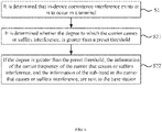
- FIG. 1 is a schematic flowchart showing a method for indicating in-device coexistence interference according to an embodiment of the present disclosure.
- the method for indicating in-device coexistence interference shown in the embodiment can be applied to terminals such as mobile phones, tablet computers, and wearable devices, etc., and the terminal can be used as user equipment to communicate with a base station, wherein it can communicate with the base station based on 5G NR.
- the method for indicating in-device coexistence interference may include the following steps:
- the terminal in the case that mutual interference exists between the 5G network and the network under the ISM frequency band, it can be determined that the terminal has in-device coexistence interference, and in the case that mutual interference is to occur between the 5G network and the network under the ISM frequency band, it can be determined that the terminal is to have in-device coexistence interference.
- a time period can be set in advance, called a preset time period, and then it is determined whether the terminal has in-device coexistence interference in the preset time period after the current moment. If the terminal has in-device coexistence interference in the preset time period after the current moment, it is determined that the terminal is to have in-device coexistence interference.
- a carrier frequency of a carrier (the carrier frequency may refer to a frequency of a center frequency point of the carrier) that causes or suffers interference, and information of a sub-band in the carrier that causes or suffers interference, are sent to a base station, wherein the carrier contains at least one sub-band.
- the in-device coexistence interference to occur may mean that the terminal has the in-device coexistence interference in the preset time period after the current moment.
- the preset time period can be configured by the base station or set by the terminal itself. If the in-device coexistence interference is the in-device coexistence interference to occur, the terminal can further send the time when the in-device coexistence interference occurs in the future, to the base station, so that the base station can solve the in-device coexistence interference in time, for example, it can solve it directly at the time, or can solved it when the time arrives.
- the terminal when the terminal has or is to have in-device coexistence interference, the terminal can first determine whether the in-device coexistence interference existing or to occur can be solved by itself, and only when it is judged that it cannot be solved by itself, it sends the information of the sub-band of the carrier frequency, to the base station.
- a bandwidth of the carrier in the 4G network is relatively small, generally about 20MHz, and in general, the granularity of the interference from the network under the ISM frequency band that the carrier in the 4G network suffers, or to the network under the ISM frequency band that the carrier in the 4G network causes, is about 20MHz as well. That is to say, for the carrier that causes or suffers interference, its entire bandwidth causes or suffers interference, so the terminal only needs to report the frequency point to the base station, and then the base station can determine that the entire carrier corresponding to the frequency point causes or suffers interference.
- 4G LTE Long Term Evolution
- the terminal is based on 5G network communication
- a bandwidth of the carrier in the 5G network can reach 100MHz (for example, the FR1 frequency band) or even 400MHz (for example, the FR2 frequency band)
- the granularity of the interference from the network under the ISM frequency band that the carrier in the 5G network suffers, or to the network under the ISM frequency band that the carrier in the 5G network causes is not limited to 20MHz, so only reporting the frequency point to the base station cannot make the base station to determine which frequency band in the carrier causes or suffers interference.
- the terminal in the case that the terminal has or is to have in-device coexistence interference, it can send the carrier frequency of the carrier that causes or suffers interference, to the base station, so that the base station can determine the carrier that causes or suffers interference according to the carrier frequency.
- it can send information of sub-band in the carrier that causes or suffers interference, to the base station, so that the base station can determine the specific sub-band in the carrier that causes or suffers interference according to the information of the sub-band.
- the base station can accurately determine which sub-band in the carrier used for terminal communication causes or suffers interference according to the carrier frequency and the information of the sub-band reported by the terminal, so that the base station can accurately determine how to resolve the in-device coexistence interference that exists or is to occur in the terminal.
- a carrier A with a carrier frequency of X in the 5G network used by the terminal suffers interference from a network under the ISM frequency band, a bandwidth of the carrier A is 100 MHz, the carrier A contains 5 sub-bands, and each of the sub-bands has a bandwidth of 20 MHz (the bandwidths of the respective sub-bands can be unequal as well, which can be set as needed).
- the terminal can send the carrier frequency X of the carrier A and identification information of the second sub-band to the base station, such that the base station can determine that the carrier A in the 5G network used by the terminal suffers interference according to the carrier frequency X, and can accurately determine that the second sub-band of the carrier A suffers interference according to the identification information of the second sub-band, so as to accurately determine the specific frequency band in the carrier that suffers interference, so that the base station can accurately determine how to solve the in-device coexistence interference that exists or is to occur in the terminal.
- one or more carriers may suffer interference from the network under the ISM frequency band, or cause interference to the network under the ISM frequency band, so the carrier frequency of the carrier that causes or suffers interference sent by the terminal to the base station, may be the carrier frequency of one carrier, or the carrier frequencies of a plurality of carriers.
- the information of the sub-band in the carrier that causes or suffers interference sent by the terminal to the base station may be the information of one sub-carrier, or the information of a plurality of sub-carriers.
- the information of the sub-band includes: a frequency offset of a frequency point of the sub-band with respect to the carrier frequency, and a bandwidth of the sub-band.
- the information of the sub-band reported by the terminal to the base station may include the frequency offset of the frequency point of the sub-band with respect to the carrier frequency, and the bandwidth of the sub-band.
- the base station can determine offset amount of the frequency point of the sub-band with respect to the carrier frequency according to the frequency offset, and then can determine a start bandwidth and a cut-off bandwidth of the sub-band according to the bandwidth of the sub-band.
- the carrier frequency is X
- the frequency offset is Y
- the bandwidth of the sub-band is 20 MHz
- the frequency point is a start frequency point of the sub-band
- FIG. 2 is a schematic flowchart showing another method for indicating in-device coexistence interference according to an embodiment of the present disclosure. As shown in FIG. 2 , the method further includes:
- step S3 receiving first configuration information sent by the base station; wherein the first configuration information is configured to indicate at least one of the frequency offset, a number of the sub-bands, and the bandwidth of the sub-band, and other items are predetermined.
- the base station may configure at least one of the frequency offset, the number of sub-bands, and the bandwidth of the sub-band, and the other items may be predetermined.
- the first configuration information is configured to indicate the frequency offset, and the number of sub-bands and the bandwidth of the sub-band are predetermined.
- the first configuration information is configured to indicate the frequency offset and the number of sub-bands, and the bandwidth of the sub-band is predetermined.
- the first configuration information is configured to indicate the frequency offset, the number of the sub-bands, and the bandwidth of the sub-band, then there is no need to predetermine the frequency offset of the sub-band, the number of the sub-bands, or the bandwidth of the sub-band.
- step S3 can be adjusted as required. For example, it can be executed before step S1 as shown in FIG. 2 , or it can be executed between step S1 and step S2.
- the information of the sub-band includes: the frequency point of the sub-band, and the bandwidth of the sub-band.
- the information of the sub-band reported by the terminal to the base station may include the frequency point of the sub-band, and the bandwidth of the sub-band.
- the base station can determine which sub-band in the carrier suffers or causes interference according to the frequency point of the sub-band, and then can determine the start bandwidth and the cut-off bandwidth of the sub-band according to the bandwidth of the sub-band.
- the base station can determine that the sub-carrier suffers or causes interference is specifically from Z to Z+20 MHz in the carrier A.
- the frequency point of the sub-band in any of the above embodiments may be a center frequency point of the sub-band, or the start frequency point of the sub-band, which can be specifically set as required, or can be pre-appointed between the terminal and the base station.
- the terminal and the base station pre-appoint that the frequency point uploaded by the terminal to the base station is the center frequency point of the sub-band, then the base station uses the frequency point uploaded by the terminal as the center frequency point of the sub-band to determine the sub-band.
- FIG. 3 is a schematic flowchart showing another method for indicating in-device coexistence interference according to an embodiment of the present disclosure. As shown in FIG. 3 , the method further includes:
- the base station may configure at least one of the number of sub-bands, and the bandwidth of the sub-band, and the other items may be predetermined.
- the first configuration information is configured to indicate the number of sub-bands, and the bandwidth of the sub-band is predetermined.
- the first configuration information is configured to indicate the number of sub-bands, and the bandwidth of the sub-band, so there is no need to predetermine the number of sub-bands, or the bandwidth of the sub-band.
- step S4 can be adjusted as required. For example, it can be executed before step S1 as shown in FIG. 3 , or it can be executed between step S1 and step S2.
- the carrier contains a plurality of sub-bands, and the information of the sub-band includes: identification information associated with the sub-band, wherein the identification information includes but is not limited to a sequence number of the sub-band, and a name of the sub-band.
- the information of the sub-band may include the identification information associated with the sub-band, and the base station may pre-store an association relationship between the identification information and the sub-band, and then after receiving the identification information, retrieve the sub-band indicating the association of the information based on the association relationship.
- a carrier A with a carrier frequency of X suffers interference
- a bandwidth of the carrier A is 100 MHz
- the carrier A contains 5 sub-bands
- each of the sub-bands has a bandwidth of 20 MHz.
- the terminal can send the carrier frequency X of the carrier A, and a sequence number of the second sub-band, for example being 2, to the base station, so that the base station can determine according to the carrier frequency X that the carrier A in the 5G network used by the terminal suffers interference, and can accurately determine according to the sequence number 2 that specifically the second sub-band in the carrier A suffers interference, so that the specific frequency band in the carrier that suffers interference can be accurately determined, so that the base station can accurately determine how to solve the in-device coexistence interference that exists or is to occur in the terminal.
- the sub-band is a bandwidth part (BWP for short).
- the carrier in the 5G network used by the terminal can be pre-configured as a plurality of bandwidth parts, that is, the carrier contains a plurality of bandwidth parts, then, in the case that the terminal has or is to have in-device coexistence interference, the terminal sends the information of the sub-band to the base station, specifically, may send information of the bandwidth part.
- the base station Since the bandwidth part is pre-configured by the base station, the base station already knows identification information, a start bandwidth, and a cut-off bandwidth of each bandwidth part in advance. Therefore, using the bandwidth part as a sub-bandwidth, if only the terminal sends the identification information of the bandwidth part to the base station, it enables the base station to accurately determine the bandwidth part corresponding to the identification information, without sending other information related to the bandwidth part, which is beneficial to reduce communication burden between the terminal and the base station.
- FIG. 4 is a schematic flowchart showing another method for indicating in-device coexistence interference according to an embodiment of the present disclosure. As shown in FIG. 4 , the method further includes: In step S5, information of an interference direction of the carrier is sent to the base station.
- the terminal may further send the information of the interference direction of the carrier to the base station, so that the base station can determine that whether the carrier in the network of a provider (including but not limited to 5G network) used by the terminal suffers interference from a network in other frequency band, or causes interference to a network in other frequency band, so that the base station can accurately determine how to solve the in-device coexistence interference that exists or is to occur in the terminal.
- a provider including but not limited to 5G network
- the carrier A in the 5G network used by the terminal suffers interference from the network under the ISM frequency band, then the information of the interference direction can be that the network under the ISM frequency band interferes with the carrier A.
- the carrier A in the 5G network used by the terminal causes interference to the network under the ISM frequency band, then the information of the interference direction can be that the carrier A interferes with the network under the ISM frequency band.
- the base station can determine how to solve the in-device coexistence interference that exists or is to occur in the terminal.
- the information of the interference direction is that the carrier in the network of the provider suffers interference from the network in other frequency band, and the priority of the network of the provider is higher, then a power of signal communicating with the terminal can be increased, so that the terminal can receive the information carried by the carrier in the network of the provider.
- the information of the interference direction is that the carrier in the network of the provider causes interference to the network in other frequency band, and the priority of the network in the other frequency bands is higher, then communication between the carrier in the network of the provider and the terminal can be suspended, so that the terminal can receive information in the network with a higher priority first.
- the information of the interference direction is not limited to the carrier in the network of the provider suffering interference from the network in other frequency band, or causing interference to the network in other frequency band. It can be interference between the networks of the providers, such as interference between the 4G network and the 5G network, as well.
- the in-device coexistence interference is not limited to the interference between two networks
- the information of interference direction is not limited to the interference direction between two networks.
- the in-device coexistence interference includes the interference caused by the carrier in the 4G network to the carrier in the 5G network, and the interference caused by the carrier in the 5G network to the network under the ISM frequency band
- the information of the interference direction can include two pieces, one piece indicating that the carrier in the 4G network causes interference to the carrier in the 5G network, and the other piece indicating that the carrier in the 5G network causes interference to the network under the ISM frequency band.
- the terminal communicates based on a combination of a plurality of carriers, and if the combination of the plurality of carriers suffers or causes interference, the information of the sub-band includes: combination information of sub-bands in the plurality of carriers that suffer or cause interference.
- the terminal may communicate based on a combination of a plurality of carriers, for example, it may communicate based on carrier aggregation, MRDC (Muti-RAT Dual-Connectivity), etc.
- MRDC Moti-RAT Dual-Connectivity
- what suffers interference from the network in other frequency band, or causes interference to the network in other frequency band can be a combination of sub-bands in the combined plurality of carriers, and then the terminal can report the combination information of the sub-bands in the plurality of carriers that suffer or cause interference, to the base station, so that the base station can determine the combination of which specific sub-bands that suffer or cause interference.
- the terminal communicates based on a combination of carrier C and carrier D, carrier C contains sub-bands C1, C2, and C3, and carrier D contains sub-bands D1, D2, and D3, wherein a combination of the sub-band C1 and the sub-band D2 causes interference to the network in other frequency band, then the information of the sub-band reported to the base station includes the information of the sub-band C1 and the information of the sub-band D2, for example, the information of the sub-band may be a frequency point and a bandwidth of the sub-band C1 and a frequency point and a bandwidth of the sub-band D2, according to which, the base station can determine it is the combination of the sub-band C1 and the sub-band D2 causing interference to the network in other frequency band.
- the terminal when the terminal communicates based on a combination of a plurality of carriers, what suffers interference from the network in other frequency band, or causes interference to the network in other frequency band, can be a separate sub-band in the combined plurality of carriers as well.
- the information of the sub-band is just the information of the separate sub-carrier.
- FIG. 5 is a schematic flowchart showing another method for indicating in-device coexistence interference according to an embodiment of the present disclosure. As shown in FIG. 5 , the method further includes: In step S6, information of degree to which the carrier causes or suffers interference, is sent to the base station.
- the terminal may further send the information of degree to which the carrier causes or suffers interference, to the base station, so that the base station can determine specific conditions under that the carrier causes or suffers interference, so as to accurately make an response, to ensure solving the in-device coexistence interference that exists or is to occur in the terminal. For example, if the carrier suffers interference to a greater degree, a transmitting and receiving power of the carrier can be increased by a greater magnitude, and if the carrier suffers interference to a smaller degree, the transmitting and receiving power of the carrier can be increased by a smaller magnitude.
- the information of degree includes at least one of the follows: an identification of degree, and a decibel value.
- the information of degree to which the carrier causes or suffers interference can be a specific decibel value (db value), such as causing 20 dB interference, suffering 50 dB interference, etc., or an identification of degree, wherein the terminal and the base station can pre-store an association relationship between the identification of degree and the specific decibel value.
- the terminal can determine the identification of degree corresponding to the decibel value that causes or suffers interference according to the association relationship, and then report the identification of degree to the base station.
- the base station can determine the decibel value corresponding to the identification of degree according to the association relationship, for example, the identification of degree “a” corresponds to 10 dB, the identification of degree “b” corresponds to 20 dB, and the identification of degree “c” corresponds to 30 dB, then, when the received identification of degree is "b", it can be determined that the identification of degree is "b" corresponds to 20 dB.
- association relationship between the identification of degree and the decibel value can be determined by the terminal itself, and then notified to the base station, or it can be configured by the base station to the terminal.
- FIG. 6 is a schematic flowchart showing another method for indicating in-device coexistence interference according to an embodiment of the present disclosure.
- sending the information of the carrier frequency of the carrier that causes or suffers interference, and the information of the sub-band in the carrier that causes or suffers interference, to the base station includes: In step S21, it is determined whether the degree to which the carrier causes or suffers interference, is greater than a preset threshold.
- step S22 if the degree is greater than the preset threshold, the information of the carrier frequency of the carrier that causes or suffers interference, and the information of the sub-band in the carrier that causes or suffers interference, are sent to the base station.
- the terminal does not have high requirements for communication quality, so, when the degree to which the carrier in the network used by the terminal causes or suffers interference, is low, but the communication requirements of the terminal can still be met, in this case, there is no need for the base station to solve the in-device coexistence interference.
- it can be determined whether the degree to which the carrier causes or suffers interference, is greater than a preset threshold, and when the degree is greater than the preset threshold, that is, the in-device coexistence interference cannot meet the communication requirements of the terminal, then the information of the carrier frequency of the carrier that causes or suffers interference, and the information of the sub-band in the carrier that causes or suffers interference, to the base station.
- the degree is less than or equal to the preset threshold, since the communication requirements of the terminal can still be met, there is no need to send the information of the carrier frequency of the carrier that causes or suffers interference, and the information of the sub-band in the carrier that causes or suffers interference, to the base station, so as to reduce the communication load between the terminal and the base station.
- the present disclosure further provides embodiments of device for indicating in-device coexistence interference.
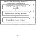
- FIG. 7 is a schematic block diagram of a device for indicating in-device coexistence interference according to an embodiment of the present disclosure.
- the method for indicating in-device coexistence interference shown in this embodiment can be applied to terminals such as mobile phones, tablet computers, and wearable devices.
- the terminal can be used as a user equipment to communicate with a base station, wherein it can communicate with the base station based on 5G NR.
- the device for indicating in-device coexistence interference may include:
- the information of the sub-band includes: a frequency offset of a frequency point of the sub-band with respect to the carrier frequency, and a bandwidth of the sub-band.
- FIG. 8 is a schematic block diagram showing another device for indicating in-device coexistence interference according to an embodiment of the present disclosure. As shown in FIG. 8 , the device further includes:
- the information of the sub-band includes: the frequency point of the sub-band, and the bandwidth of the sub-band.
- FIG. 9 is a schematic block diagram showing another device for indicating in-device coexistence interference according to an embodiment of the present disclosure. As shown in FIG. 9 , the device further includes:
- the carrier contains a plurality of sub-bands, and the information of the sub-band includes: identification information associated with the sub-band.
- the sub-band is a bandwidth part.
- the information sending module is further configured to send information of an interference direction of the carrier to the base station.
- the terminal communicates based on a combination of a plurality of carriers, and if the combination of the plurality of carriers suffers or causes interference, the information of the sub-band includes: combination information of sub-bands in the plurality of carriers that suffer or cause interference.
- the information sending module is further configured to send information of degree to which the carrier causes or suffers interference, to the base station.
- the information of degree includes at least one of the follows: an identification of degree, and a decibel value.
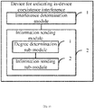
- FIG. 10 is a schematic block diagram showing another device for indicating in-device coexistence interference according to an embodiment of the present disclosure.
- the information sending module 2 includes:
- the relevant part can be refer to the part of the description of the method embodiments.
- the device embodiments described above are merely illustrative, wherein the modules described as separate components may or may not be physically separated, and the component displayed as a module may or may not be a physical module, that is, it may be located in one place, or it can be distributed to a plurality of network modules.
- a part or all of the modules can be selected according to actual needs to achieve the objects of the solutions of the embodiments, and those of ordinary skill in the art can understand and implement without creative work.
- the present disclosure further provides an electronic device, including:
- the present disclosure further provides a computer-readable storage medium, on which a computer program is stored, and when the program is executed by a processor, the steps in the methods for indicating in-device coexistence interference described in any of the foregoing embodiments are realized.
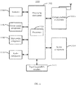
- FIG. 11 is a schematic block diagram showing an apparatus 1100 for in-device coexistence interference according to an embodiment of the present disclosure.
- the apparatus 1100 may be a mobile phone, a computer, a digital broadcasting terminal, a messaging device, a game console, a tablet device, a medical device, a fitness device, a personal digital assistant, etc.
- the apparatus 1100 may include one or more of the following components: a processing component 1102, a memory 1104, a power supply component 1106, a multimedia component 1108, an audio component 1110, an input/output (I/O) interface 1112, a sensor component 1114, and a communication component 1116.
- a processing component 1102 a memory 1104, a power supply component 1106, a multimedia component 1108, an audio component 1110, an input/output (I/O) interface 1112, a sensor component 1114, and a communication component 1116.
- the processing component 1102 generally controls the overall operations of the apparatus 1100, such as operations associated with display, telephone calls, data communications, camera operations, and recording operations.
- the processing component 1102 may include one or more processors 1120 to execute instructions, to complete all or a part of the steps of the foregoing method.
- the processing component 1102 may include one or more modules, to facilitate the interaction between the processing component 1102 and other components.
- the processing component 1102 may include a multimedia module, to facilitate the interaction between the multimedia component 1108 and the processing component 1102.
- the memory 1104 is configured to store various types of data, to support operations on the apparatus 1100. Examples of these data include: instructions for any application or method operating on the apparatus 1100, contact data, phone book data, messages, pictures, videos, etc.
- the memory 1104 can be realized by any type of volatile or non-volatile storage device or their combination, such as static random access memory (SRAM), electrically erasable programmable read-only memory (EEPROM), erasable and Programmable read-only memory (EPROM), programmable read-only memory (PROM), read-only memory (ROM), magnetic memory, flash memory, magnetic disk or optical disk.
- SRAM static random access memory
- EEPROM electrically erasable programmable read-only memory
- EPROM erasable and Programmable read-only memory
- PROM programmable read-only memory
- ROM read-only memory
- magnetic memory flash memory
- flash memory magnetic disk or optical disk.
- the power supply component 1106 provides power for various components of the apparatus 1100.
- the power supply component 1106 may include a power management system, one or more power supplies, and other components associated with the generation, management, and distribution of power for the apparatus 1100.
- the multimedia component 1108 includes a screen that provides an output interface between the apparatus 1100 and the user.
- the screen may include a liquid crystal display (LCD) and a touch panel (TP). If the screen includes a touch panel, the screen may be realized as a touch screen, to receive input signals from the user.
- the touch panel includes one or more touch sensors, to sense touch, sliding, and gestures on the touch panel. The touch sensor may not only sense the boundary of a touch or slide action, but also detect the duration and pressure related to the touch or slide operation.
- the multimedia component 1108 includes a front camera and/or a rear camera. When the apparatus 1100 is in an operation mode, such as a shooting mode or a video mode, the front camera and/or the rear camera can receive external multimedia data. Each front camera and rear camera can be a fixed optical lens system, or have focal length and optical zoom capability.
- the audio component 1110 is configured to output and/or input audio signals.
- the audio component 1110 includes a microphone (MIC), and when the apparatus 1100 is in an operation mode, such as a call mode, a recording mode, and a voice recognition mode, the microphone is configured to receive external audio signals.
- the received audio signal may be further stored in the memory 1104 or sent via the communication component 1116.
- the audio component 1110 further includes a speaker for outputting audio signals.
- the I/O interface 1112 provides an interface between the processing component 1102 and a peripheral interface module.
- the above-mentioned peripheral interface module may be a keyboard, a click wheel, a button, and the like. These buttons may include but are not limited to: home button, volume button, start button, and lock button.
- the sensor component 1114 includes one or more sensors for providing various aspects of state evaluation for the apparatus 1100.
- the sensor component 1114 can detect the on/off state of the apparatus 1100, and the relative positioning of components.
- the component is the display and the keypad of the apparatus 1100.
- the sensor component 1114 can further detect the position change of the apparatus 1100 or a component of the apparatus 1100, the presence or absence of contact between the user and the apparatus 1100, the orientation or acceleration/deceleration of the apparatus 1100, and the temperature change of the apparatus 1100.
- the sensor component 1114 may include a proximity sensor configured to detect the presence of nearby objects without physical contact.
- the sensor component 1114 may further include a light sensor, such as a CMOS or CCD image sensor, for use in imaging applications.
- the sensor component 1114 may further include an acceleration sensor, a gyroscope sensor, a magnetic sensor, a pressure sensor or a temperature sensor.
- the communication component 1116 is configured to facilitate wired or wireless communication between the apparatus 1100 and other devices.
- the apparatus 1100 can access a wireless network based on a communication standard, such as WiFi, 2G or 3G, 4G LTE, 5G NR, or a combination thereof.
- the communication component 1116 receives a broadcast signal or broadcast related information from an external broadcast management system via a broadcast channel.
- the communication component 1116 further includes a near field communication (NFC) module, to facilitate short-range communication.
- the NFC module can be realized based on radio frequency identification (RFID) technology, infrared data association (IrDA) technology, ultra-wideband (UWB) technology, Bluetooth (BT) technology and other technologies.
- RFID radio frequency identification
- IrDA infrared data association
- UWB ultra-wideband
- Bluetooth Bluetooth
- the apparatus 1100 may be realized by one or more application specific integrated circuits (ASIC), digital signal processors (DSP), digital signal processing devices (DSPD), programmable logic devices (PLD), field programmable gate array (FPGA), a controller, a microcontroller, a microprocessor, or other electronic components, to implement the method described in any of the foregoing embodiments.
- ASIC application specific integrated circuits
- DSP digital signal processors
- DSPD digital signal processing devices
- PLD programmable logic devices
- FPGA field programmable gate array
- controller a controller
- microcontroller a microcontroller
- microprocessor or other electronic components
- a non-transitory computer-readable storage medium including instructions such as a memory 1104 including instructions, and the foregoing instructions may be executed by the processor 1120 of the apparatus 1100, to complete the foregoing method.
- the non-transitory computer-readable storage medium may be ROM, random access memory (RAM), CD-ROM, magnetic tape, floppy disk, optical data storage device, etc.
Landscapes
- Engineering & Computer Science (AREA)
- Signal Processing (AREA)
- Computer Networks & Wireless Communication (AREA)
- Quality & Reliability (AREA)
- Mobile Radio Communication Systems (AREA)
Applications Claiming Priority (1)
| Application Number | Priority Date | Filing Date | Title |
|---|---|---|---|
| PCT/CN2019/091759 WO2020252664A1 (zh) | 2019-06-18 | 2019-06-18 | 设备内共存干扰指示方法和装置 |
Publications (2)
| Publication Number | Publication Date |
|---|---|
| EP3989657A1 true EP3989657A1 (de) | 2022-04-27 |
| EP3989657A4 EP3989657A4 (de) | 2023-01-25 |
Family
ID=68419113
Family Applications (1)
| Application Number | Title | Priority Date | Filing Date |
|---|---|---|---|
| EP19934286.6A Pending EP3989657A4 (de) | 2019-06-18 | 2019-06-18 | Verfahren und vorrichtung zur anzeige von koexistenzinterferenz in einer vorrichtung |
Country Status (4)
| Country | Link |
|---|---|
| US (1) | US12192150B2 (de) |
| EP (1) | EP3989657A4 (de) |
| CN (2) | CN110431904B (de) |
| WO (1) | WO2020252664A1 (de) |
Cited By (1)
| Publication number | Priority date | Publication date | Assignee | Title |
|---|---|---|---|---|
| EP4598089A4 (de) * | 2022-09-27 | 2025-10-22 | Beijing Xiaomi Mobile Software Co Ltd | Verfahren und vorrichtung zur meldung von interferenzfrequenzinformationen |
Families Citing this family (5)
| Publication number | Priority date | Publication date | Assignee | Title |
|---|---|---|---|---|
| KR20240156453A (ko) * | 2022-03-11 | 2024-10-29 | 베이징 시아오미 모바일 소프트웨어 컴퍼니 리미티드 | 간섭 정보 보고, 주파수 범위 결정 방법 및 장치 |
| CN115087111A (zh) * | 2022-05-18 | 2022-09-20 | 北京小米移动软件有限公司 | 频带资源处理方法及装置、电子设备、存储介质 |
| WO2024011516A1 (en) * | 2022-07-14 | 2024-01-18 | Zte Corporation | Methods and devices for reporting in-device coexistence interference |
| WO2024092606A1 (zh) * | 2022-11-03 | 2024-05-10 | Oppo广东移动通信有限公司 | 无线通信的方法、终端设备和网络设备 |
| WO2024073993A1 (en) * | 2023-02-03 | 2024-04-11 | Lenovo (Beijing) Limited | Method and apparatus for avoiding in-device coexistence interference |
Family Cites Families (19)
| Publication number | Priority date | Publication date | Assignee | Title |
|---|---|---|---|---|
| CN102457885B (zh) | 2010-10-29 | 2016-03-30 | 中兴通讯股份有限公司 | 一种测量处理方法及系统 |
| CN102595543A (zh) * | 2011-01-10 | 2012-07-18 | 中兴通讯股份有限公司 | 一种终端内多种无线技术共存的通信方法和系统 |
| KR20120092072A (ko) * | 2011-02-10 | 2012-08-20 | 주식회사 팬택 | 무선통신 시스템에서 기기내 공존 간섭을 조정하는 장치 및 방법 |
| US9137804B2 (en) * | 2011-06-21 | 2015-09-15 | Mediatek Inc. | Systems and methods for different TDD configurations in carrier aggregation |
| RU2627734C2 (ru) | 2011-12-05 | 2017-08-11 | Самсунг Электроникс Ко., Лтд. | Способ и система для обработки помех сосуществования внутри устройства в пользовательском оборудовании |
| CN103391180A (zh) | 2012-05-10 | 2013-11-13 | 中国移动通信集团公司 | 一种终端内不同通信模块间共存的方法和装置 |
| KR20130126382A (ko) | 2012-05-11 | 2013-11-20 | 주식회사 팬택 | 다수 요소 반송파 시스템에서 기기 내 공존 간섭을 제어하는 장치 및 방법 |
| GB2512877A (en) * | 2013-04-09 | 2014-10-15 | Nec Corp | Communication system |
| US20160135213A1 (en) * | 2013-07-04 | 2016-05-12 | Qualcomm Incorporated | Communications associated with a user equipment capable of communicating with multiple radio access technologies |
| CN104521284B (zh) | 2013-07-31 | 2018-05-04 | 华为技术有限公司 | 切换方法、基站和用户设备 |
| WO2017030480A1 (en) * | 2015-08-14 | 2017-02-23 | Telefonaktiebolaget Lm Ericsson (Publ) | Signaling of idc problems |
| CN107113012B (zh) * | 2015-08-31 | 2019-11-29 | 华为技术有限公司 | 调度方法和设备 |
| US10624108B2 (en) * | 2017-04-05 | 2020-04-14 | Qualcomm Incorporated | Coexistence interference mitigation in wireless systems |
| DE112017008206T5 (de) | 2017-11-17 | 2020-08-13 | Apple Inc. | Vorübergehende Behandlung der Funktionen drahtloser Kommunikationsvorrichtungen |
| CN108401537A (zh) | 2018-02-11 | 2018-08-14 | 北京小米移动软件有限公司 | 设备内共存干扰协调方法、装置、用户设备及通信设备 |
| KR102547937B1 (ko) * | 2018-08-08 | 2023-06-26 | 삼성전자주식회사 | 무선 통신 시스템에서 데이터를 송수신하는 방법 및 장치 |
| CN118055503A (zh) * | 2019-02-01 | 2024-05-17 | 华为技术有限公司 | 一种通信的方法和装置 |
| US11388637B1 (en) * | 2021-01-08 | 2022-07-12 | Qualcomm Incorporated | Cell selection for conditional handover |
| US20240237107A1 (en) * | 2021-05-07 | 2024-07-11 | Telefonaktiebolaget Lm Ericsson (Publ) | Methods and Apparatuses for Configuring a Multi-Link Wireless Local Area Network Connection Between a Wireless Device and a First Wireless Local Area Network Termination Node |
-
2019
- 2019-06-18 WO PCT/CN2019/091759 patent/WO2020252664A1/zh not_active Ceased
- 2019-06-18 CN CN201980001108.3A patent/CN110431904B/zh active Active
- 2019-06-18 CN CN202311115136.2A patent/CN117014095A/zh active Pending
- 2019-06-18 US US17/620,664 patent/US12192150B2/en active Active
- 2019-06-18 EP EP19934286.6A patent/EP3989657A4/de active Pending
Cited By (1)
| Publication number | Priority date | Publication date | Assignee | Title |
|---|---|---|---|---|
| EP4598089A4 (de) * | 2022-09-27 | 2025-10-22 | Beijing Xiaomi Mobile Software Co Ltd | Verfahren und vorrichtung zur meldung von interferenzfrequenzinformationen |
Also Published As
| Publication number | Publication date |
|---|---|
| CN117014095A (zh) | 2023-11-07 |
| US20220360416A1 (en) | 2022-11-10 |
| WO2020252664A1 (zh) | 2020-12-24 |
| CN110431904B (zh) | 2023-10-10 |
| EP3989657A4 (de) | 2023-01-25 |
| US12192150B2 (en) | 2025-01-07 |
| CN110431904A (zh) | 2019-11-08 |
Similar Documents
| Publication | Publication Date | Title |
|---|---|---|
| US12192150B2 (en) | Method and device for indication of in-device coexistence interference | |
| US12127240B2 (en) | Methods and apparatuses for triggering bandwidth part handover, and methods and apparatuses for information configuration | |
| US11191085B2 (en) | Method and apparatus for coordinating in-device coexistence interference, user equipment and communication device | |
| EP3651530B1 (de) | Verfahren und vorrichtung zur interferenzkoordination, basisstation und benutzergerät | |
| US12432764B2 (en) | Method for in-device coexistence interference indication and method and apparatus for in-device coexistence interference receiving | |
| JP7253078B2 (ja) | ページング応答方法と装置、ページング方法と装置 | |
| US11350394B2 (en) | Resource configuration method, apparatus, user equipment, and base station | |
| US12382493B2 (en) | Slot format indication method and apparatus | |
| EP3716665A1 (de) | Übertragungskonfigurationsverfahren und -apparat | |
| US20250150876A1 (en) | Measurement method, terminal, and network device and non-transitory computer-readable storage medium | |
| WO2021012114A1 (zh) | 设备内共存干扰指示方法、接收方法和装置 | |
| US11503642B2 (en) | Method and device for determining an uplink-downlink switching point | |
| US11800547B2 (en) | Information transmission method and device | |
| US12549974B2 (en) | Method and apparatus for detecting IDC, and method and apparatus for indicating IDC detection | |
| US11937296B2 (en) | Monitoring method and apparatus, device, and storage medium | |
| US11812386B2 (en) | Configuration adjustment methods, apparatuses, electronic device and computer readable storage medium | |
| US11799705B2 (en) | Message transmission method and device | |
| JP7659127B2 (ja) | 端末能力報告方法及び装置、並びに記憶媒体 | |
| CN110603847B (zh) | 小区重选方法和装置、电子设备以及计算机可读存储介质 | |
| US20260025821A1 (en) | Methods and apparatus for determining number of uplink transmission links, communication apparatus and storage medium | |
| US20240275570A1 (en) | Information configuration method and apparatus, user equipment, base station, and storage medium |
Legal Events
| Date | Code | Title | Description |
|---|---|---|---|
| STAA | Information on the status of an ep patent application or granted ep patent |
Free format text: STATUS: THE INTERNATIONAL PUBLICATION HAS BEEN MADE |
|
| PUAI | Public reference made under article 153(3) epc to a published international application that has entered the european phase |
Free format text: ORIGINAL CODE: 0009012 |
|
| STAA | Information on the status of an ep patent application or granted ep patent |
Free format text: STATUS: REQUEST FOR EXAMINATION WAS MADE |
|
| 17P | Request for examination filed |
Effective date: 20220113 |
|
| AK | Designated contracting states |
Kind code of ref document: A1 Designated state(s): AL AT BE BG CH CY CZ DE DK EE ES FI FR GB GR HR HU IE IS IT LI LT LU LV MC MK MT NL NO PL PT RO RS SE SI SK SM TR |
|
| DAV | Request for validation of the european patent (deleted) | ||
| DAX | Request for extension of the european patent (deleted) | ||
| A4 | Supplementary search report drawn up and despatched |
Effective date: 20221223 |
|
| RIC1 | Information provided on ipc code assigned before grant |
Ipc: H04W 88/06 20090101ALI20221219BHEP Ipc: H04L 5/00 20060101ALI20221219BHEP Ipc: H04J 11/00 20060101ALI20221219BHEP Ipc: H04W 72/04 20090101AFI20221219BHEP |
|
| STAA | Information on the status of an ep patent application or granted ep patent |
Free format text: STATUS: EXAMINATION IS IN PROGRESS |
|
| 17Q | First examination report despatched |
Effective date: 20251002 |