EP3990102B1 - Steuerung der funktionellen elektrischen stimulation mit aktionspotentialen einer motoreinheit - Google Patents
Steuerung der funktionellen elektrischen stimulation mit aktionspotentialen einer motoreinheit Download PDFInfo
- Publication number
- EP3990102B1 EP3990102B1 EP20743425.9A EP20743425A EP3990102B1 EP 3990102 B1 EP3990102 B1 EP 3990102B1 EP 20743425 A EP20743425 A EP 20743425A EP 3990102 B1 EP3990102 B1 EP 3990102B1
- Authority
- EP
- European Patent Office
- Prior art keywords
- electrodes
- action potentials
- extracted
- garment
- potentials
- Prior art date
- Legal status (The legal status is an assumption and is not a legal conclusion. Google has not performed a legal analysis and makes no representation as to the accuracy of the status listed.)
- Active
Links
Images




Classifications
-
- A—HUMAN NECESSITIES
- A61—MEDICAL OR VETERINARY SCIENCE; HYGIENE
- A61N—ELECTROTHERAPY; MAGNETOTHERAPY; RADIATION THERAPY; ULTRASOUND THERAPY
- A61N1/00—Electrotherapy; Circuits therefor
- A61N1/18—Applying electric currents by contact electrodes
- A61N1/32—Applying electric currents by contact electrodes alternating or intermittent currents
- A61N1/36—Applying electric currents by contact electrodes alternating or intermittent currents for stimulation
- A61N1/36014—External stimulators, e.g. with patch electrodes
- A61N1/3603—Control systems
- A61N1/36031—Control systems using physiological parameters for adjustment
-
- A—HUMAN NECESSITIES
- A61—MEDICAL OR VETERINARY SCIENCE; HYGIENE
- A61B—DIAGNOSIS; SURGERY; IDENTIFICATION
- A61B5/00—Measuring for diagnostic purposes; Identification of persons
- A61B5/103—Measuring devices for testing the shape, pattern, colour, size or movement of the body or parts thereof, for diagnostic purposes
- A61B5/11—Measuring movement of the entire body or parts thereof, e.g. head or hand tremor or mobility of a limb
-
- A—HUMAN NECESSITIES
- A61—MEDICAL OR VETERINARY SCIENCE; HYGIENE
- A61B—DIAGNOSIS; SURGERY; IDENTIFICATION
- A61B5/00—Measuring for diagnostic purposes; Identification of persons
- A61B5/24—Detecting, measuring or recording bioelectric or biomagnetic signals of the body or parts thereof
- A61B5/316—Modalities, i.e. specific diagnostic methods
- A61B5/389—Electromyography [EMG]
- A61B5/395—Details of stimulation, e.g. nerve stimulation to elicit EMG response
-
- A—HUMAN NECESSITIES
- A61—MEDICAL OR VETERINARY SCIENCE; HYGIENE
- A61B—DIAGNOSIS; SURGERY; IDENTIFICATION
- A61B5/00—Measuring for diagnostic purposes; Identification of persons
- A61B5/48—Other medical applications
- A61B5/4851—Prosthesis assessment or monitoring
-
- A—HUMAN NECESSITIES
- A61—MEDICAL OR VETERINARY SCIENCE; HYGIENE
- A61B—DIAGNOSIS; SURGERY; IDENTIFICATION
- A61B5/00—Measuring for diagnostic purposes; Identification of persons
- A61B5/68—Arrangements of detecting, measuring or recording means, e.g. sensors, in relation to patient
- A61B5/6801—Arrangements of detecting, measuring or recording means, e.g. sensors, in relation to patient specially adapted to be attached to or worn on the body surface
- A61B5/6813—Specially adapted to be attached to a specific body part
- A61B5/6824—Arm or wrist
-
- A—HUMAN NECESSITIES
- A61—MEDICAL OR VETERINARY SCIENCE; HYGIENE
- A61B—DIAGNOSIS; SURGERY; IDENTIFICATION
- A61B5/00—Measuring for diagnostic purposes; Identification of persons
- A61B5/72—Signal processing specially adapted for physiological signals or for diagnostic purposes
- A61B5/7235—Details of waveform analysis
- A61B5/725—Details of waveform analysis using specific filters therefor, e.g. Kalman or adaptive filters
-
- A—HUMAN NECESSITIES
- A61—MEDICAL OR VETERINARY SCIENCE; HYGIENE
- A61B—DIAGNOSIS; SURGERY; IDENTIFICATION
- A61B5/00—Measuring for diagnostic purposes; Identification of persons
- A61B5/72—Signal processing specially adapted for physiological signals or for diagnostic purposes
- A61B5/7235—Details of waveform analysis
- A61B5/7264—Classification of physiological signals or data, e.g. using neural networks, statistical classifiers, expert systems or fuzzy systems
- A61B5/7267—Classification of physiological signals or data, e.g. using neural networks, statistical classifiers, expert systems or fuzzy systems involving training the classification device
-
- A—HUMAN NECESSITIES
- A61—MEDICAL OR VETERINARY SCIENCE; HYGIENE
- A61F—FILTERS IMPLANTABLE INTO BLOOD VESSELS; PROSTHESES; DEVICES PROVIDING PATENCY TO, OR PREVENTING COLLAPSING OF, TUBULAR STRUCTURES OF THE BODY, e.g. STENTS; ORTHOPAEDIC, NURSING OR CONTRACEPTIVE DEVICES; FOMENTATION; TREATMENT OR PROTECTION OF EYES OR EARS; BANDAGES, DRESSINGS OR ABSORBENT PADS; FIRST-AID KITS
- A61F2/00—Filters implantable into blood vessels; Prostheses, i.e. artificial substitutes or replacements for parts of the body; Appliances for connecting them with the body; Devices providing patency to, or preventing collapsing of, tubular structures of the body, e.g. stents
- A61F2/50—Prostheses not implantable in the body
- A61F2/68—Operating or control means
- A61F2/70—Operating or control means electrical
- A61F2/72—Bioelectric control, e.g. myoelectric
-
- A—HUMAN NECESSITIES
- A61—MEDICAL OR VETERINARY SCIENCE; HYGIENE
- A61F—FILTERS IMPLANTABLE INTO BLOOD VESSELS; PROSTHESES; DEVICES PROVIDING PATENCY TO, OR PREVENTING COLLAPSING OF, TUBULAR STRUCTURES OF THE BODY, e.g. STENTS; ORTHOPAEDIC, NURSING OR CONTRACEPTIVE DEVICES; FOMENTATION; TREATMENT OR PROTECTION OF EYES OR EARS; BANDAGES, DRESSINGS OR ABSORBENT PADS; FIRST-AID KITS
- A61F6/00—Contraceptive devices; Pessaries; Applicators therefor
- A61F6/06—Contraceptive devices; Pessaries; Applicators therefor for use by females
- A61F6/08—Pessaries, i.e. devices worn in the vagina to support the uterus, remedy a malposition or prevent conception, e.g. combined with devices protecting against contagion
-
- A—HUMAN NECESSITIES
- A61—MEDICAL OR VETERINARY SCIENCE; HYGIENE
- A61N—ELECTROTHERAPY; MAGNETOTHERAPY; RADIATION THERAPY; ULTRASOUND THERAPY
- A61N1/00—Electrotherapy; Circuits therefor
- A61N1/02—Details
- A61N1/04—Electrodes
- A61N1/0404—Electrodes for external use
- A61N1/0408—Use-related aspects
- A61N1/0452—Specially adapted for transcutaneous muscle stimulation [TMS]
-
- A—HUMAN NECESSITIES
- A61—MEDICAL OR VETERINARY SCIENCE; HYGIENE
- A61N—ELECTROTHERAPY; MAGNETOTHERAPY; RADIATION THERAPY; ULTRASOUND THERAPY
- A61N1/00—Electrotherapy; Circuits therefor
- A61N1/02—Details
- A61N1/04—Electrodes
- A61N1/0404—Electrodes for external use
- A61N1/0472—Structure-related aspects
- A61N1/0484—Garment electrodes worn by the patient
-
- A—HUMAN NECESSITIES
- A61—MEDICAL OR VETERINARY SCIENCE; HYGIENE
- A61N—ELECTROTHERAPY; MAGNETOTHERAPY; RADIATION THERAPY; ULTRASOUND THERAPY
- A61N1/00—Electrotherapy; Circuits therefor
- A61N1/02—Details
- A61N1/04—Electrodes
- A61N1/05—Electrodes for implantation or insertion into the body, e.g. heart electrode
- A61N1/0551—Spinal or peripheral nerve electrodes
-
- A—HUMAN NECESSITIES
- A61—MEDICAL OR VETERINARY SCIENCE; HYGIENE
- A61N—ELECTROTHERAPY; MAGNETOTHERAPY; RADIATION THERAPY; ULTRASOUND THERAPY
- A61N1/00—Electrotherapy; Circuits therefor
- A61N1/18—Applying electric currents by contact electrodes
- A61N1/32—Applying electric currents by contact electrodes alternating or intermittent currents
- A61N1/36—Applying electric currents by contact electrodes alternating or intermittent currents for stimulation
- A61N1/36003—Applying electric currents by contact electrodes alternating or intermittent currents for stimulation of motor muscles, e.g. for walking assistance
-
- G—PHYSICS
- G16—INFORMATION AND COMMUNICATION TECHNOLOGY [ICT] SPECIALLY ADAPTED FOR SPECIFIC APPLICATION FIELDS
- G16H—HEALTHCARE INFORMATICS, i.e. INFORMATION AND COMMUNICATION TECHNOLOGY [ICT] SPECIALLY ADAPTED FOR THE HANDLING OR PROCESSING OF MEDICAL OR HEALTHCARE DATA
- G16H15/00—ICT specially adapted for medical reports, e.g. generation or transmission thereof
-
- G—PHYSICS
- G16—INFORMATION AND COMMUNICATION TECHNOLOGY [ICT] SPECIALLY ADAPTED FOR SPECIFIC APPLICATION FIELDS
- G16H—HEALTHCARE INFORMATICS, i.e. INFORMATION AND COMMUNICATION TECHNOLOGY [ICT] SPECIALLY ADAPTED FOR THE HANDLING OR PROCESSING OF MEDICAL OR HEALTHCARE DATA
- G16H20/00—ICT specially adapted for therapies or health-improving plans, e.g. for handling prescriptions, for steering therapy or for monitoring patient compliance
- G16H20/30—ICT specially adapted for therapies or health-improving plans, e.g. for handling prescriptions, for steering therapy or for monitoring patient compliance relating to physical therapies or activities, e.g. physiotherapy, acupressure or exercising
-
- G—PHYSICS
- G16—INFORMATION AND COMMUNICATION TECHNOLOGY [ICT] SPECIALLY ADAPTED FOR SPECIFIC APPLICATION FIELDS
- G16H—HEALTHCARE INFORMATICS, i.e. INFORMATION AND COMMUNICATION TECHNOLOGY [ICT] SPECIALLY ADAPTED FOR THE HANDLING OR PROCESSING OF MEDICAL OR HEALTHCARE DATA
- G16H40/00—ICT specially adapted for the management or administration of healthcare resources or facilities; ICT specially adapted for the management or operation of medical equipment or devices
- G16H40/60—ICT specially adapted for the management or administration of healthcare resources or facilities; ICT specially adapted for the management or operation of medical equipment or devices for the operation of medical equipment or devices
- G16H40/63—ICT specially adapted for the management or administration of healthcare resources or facilities; ICT specially adapted for the management or operation of medical equipment or devices for the operation of medical equipment or devices for local operation
-
- G—PHYSICS
- G16—INFORMATION AND COMMUNICATION TECHNOLOGY [ICT] SPECIALLY ADAPTED FOR SPECIFIC APPLICATION FIELDS
- G16H—HEALTHCARE INFORMATICS, i.e. INFORMATION AND COMMUNICATION TECHNOLOGY [ICT] SPECIALLY ADAPTED FOR THE HANDLING OR PROCESSING OF MEDICAL OR HEALTHCARE DATA
- G16H40/00—ICT specially adapted for the management or administration of healthcare resources or facilities; ICT specially adapted for the management or operation of medical equipment or devices
- G16H40/60—ICT specially adapted for the management or administration of healthcare resources or facilities; ICT specially adapted for the management or operation of medical equipment or devices for the operation of medical equipment or devices
- G16H40/67—ICT specially adapted for the management or administration of healthcare resources or facilities; ICT specially adapted for the management or operation of medical equipment or devices for the operation of medical equipment or devices for remote operation
-
- G—PHYSICS
- G16—INFORMATION AND COMMUNICATION TECHNOLOGY [ICT] SPECIALLY ADAPTED FOR SPECIFIC APPLICATION FIELDS
- G16H—HEALTHCARE INFORMATICS, i.e. INFORMATION AND COMMUNICATION TECHNOLOGY [ICT] SPECIALLY ADAPTED FOR THE HANDLING OR PROCESSING OF MEDICAL OR HEALTHCARE DATA
- G16H50/00—ICT specially adapted for medical diagnosis, medical simulation or medical data mining; ICT specially adapted for detecting, monitoring or modelling epidemics or pandemics
- G16H50/30—ICT specially adapted for medical diagnosis, medical simulation or medical data mining; ICT specially adapted for detecting, monitoring or modelling epidemics or pandemics for calculating health indices; for individual health risk assessment
-
- G—PHYSICS
- G16—INFORMATION AND COMMUNICATION TECHNOLOGY [ICT] SPECIALLY ADAPTED FOR SPECIFIC APPLICATION FIELDS
- G16H—HEALTHCARE INFORMATICS, i.e. INFORMATION AND COMMUNICATION TECHNOLOGY [ICT] SPECIALLY ADAPTED FOR THE HANDLING OR PROCESSING OF MEDICAL OR HEALTHCARE DATA
- G16H50/00—ICT specially adapted for medical diagnosis, medical simulation or medical data mining; ICT specially adapted for detecting, monitoring or modelling epidemics or pandemics
- G16H50/50—ICT specially adapted for medical diagnosis, medical simulation or medical data mining; ICT specially adapted for detecting, monitoring or modelling epidemics or pandemics for simulation or modelling of medical disorders
Definitions
- FES functional electrical stimulation
- EMG electromyography
- SCI spinal cord injury
- FES devices apply electrical stimulation via surface or intramuscular electrodes in order to stimulate muscle contraction and consequent motion of an arm, leg, hand, or other body part.
- Use of surface electrodes, as opposed to intramuscular electrodes, is advantageously painless and non-invasive.
- an FES device operatively connected with the paralyzed body portion has the potential to restore volitional control of the hand, forearm, and wrist.
- BCI brain-computer interface
- This approach has certain disadvantages, notably the invasive nature of the intracortical electrodes and the complexity of brain electrical activity. Even assuming the electrodes are measuring only motor cortex activity, this activity encompasses volitional intent relating to the entire patient's body. This makes decoding volitional intent as respecting a specific body part (e.g., the wrist, or even more precisely a particular muscle of the wrist) challenging. In the case of a stroke patient, effects of the stroke on brain electrical activity may further complicate the decoding of the brain electrical activity.
- Patent application WO2016/196797 discloses systems, methods, and devices for interpreting neural signals to determine a desired movement of a target, transmitting electrical signals to the target, and dynamically monitoring subsequent neural signals or movement of the target to change the signal being delivered if necessary, so that the desired movement is achieved.
- the neural signals are decoded using a feature extractor, decoder(s) and a body state observer to determine the electrical signals that should be sent.
- a therapeutic or diagnostic device comprises a wearable electrodes garment including electrodes disposed to contact skin when the wearable electrodes garment is worn, and an electronic controller operatively connected with the electrodes.
- the electronic controller is programmed to perform a method including receiving surface electromyography (EMG) signals via the electrodes and extracting one or more motor unit (MU) action potentials from the surface EMG signals.
- the method may further include identifying an intended movement based at least on feature representing the one or more extracted MU action potentials and delivering functional electrical stimulation (FES) effective to implement the intended movement via the electrodes of the wearable electrodes garment.
- the method may further include generating a patient performance report based at least on a comparison of features representing the one or more extracted MU action potentials and features representing expected and/or baseline MU action potentials for a known intended movement.
- a therapeutic device comprises a wearable electrodes garment including electrodes disposed to contact skin when the wearable electrodes garment is worn, and electronic controller operatively connected with the electrodes.
- the electronic processor is programmed to perform a method including: receiving surface EMG signals via the electrodes; extracting one or more MU action potentials from the surface EMG signals wherein each MU comprises a motor neuron and skeletal muscle fibers innervated by that motor neuron and each MU action potential comprises the electrical signal carried by the motor neuron of the corresponding MU; identifying an intended movement based on features including at least features representing the one or more extracted MU action potentials; and delivering FES effective to implement the intended movement via the electrodes of the wearable electrodes garment.
- a therapeutic or diagnostic method comprises receiving surface EMG signals via electrodes of a wearable electrodes garment and, using an electronic processor: extracting one or more motor unit (MU) action potentials from the surface EMG signals; and one of (i) identifying an intended movement based at least on the one or more extracted MU action potentials delivering functional electrical stimulation (FES) effective to implement the intended movement via the electrodes of the wearable electrodes garment or (ii) generating a patient performance report based at least on a comparison of the one or more extracted MU action potentials and expected and/or baseline MU action potentials for a known intended movement wherein each MU comprises a motor neuron and skeletal muscle fibers innervated by that motor neuron and each MU action potential comprises the electrical signal carried by the motor neuron of the corresponding MU.
- FES functional electrical stimulation
- EMG electromyography
- EMG signals for volitional FES control is challenging. If EMG signals are present at all in the paralyzed body part, they are expected to be greatly attenuated compared with EMG signals in a healthy person. This might be countered to some degree by use of intramuscular electrodes (e.g. needle electrodes) to measure the EMG signals, but invasive intramuscular electrodes are often unacceptable to the patient in the case of a wrist, arm, or other flexing body part.
- Surface EMG signals can be measured using electrodes contacting the skin, which may be more acceptable to the patient.
- the surface EMG signals are weaker than intramuscular EMG signals (and, as noted, the EMG signals are already expected to be greatly attenuated in the paralyzed body part due to the paralysis).
- a still further difficulty is that the EMG signals can be difficult to decode, as they are not direct metrics of volitional intent but rather are a measure of muscular activity stimulated by the volitional intent.
- the muscular contractions producing the EMG signals in a paralyzed body part may not simply be attenuated versions of the intended muscular contractions, but instead may include involuntary tremors or other non-volitional muscle activity.
- measuring motor unit provides additional information that can be used in addressing the above-mentioned difficulties.
- a motor unit is the combination of a motor neuron and the skeletal muscle fibers innervated by that motor neuron.
- the MU action potential is the electrical signal carried by the motor neuron.
- the MU action potential directly captures the volitional intent of the paralyzed patient (albeit likely attenuated due to the paralysis).
- the volitional intent to perform a movement of a body part translates, at the MU level, into various parameters such as (in the illustrative examples): (i) the number of MUs recruited to perform the movement; and (ii) the discharge rate (aka firing rate, pulse rate) of the recruited motor units.
- the number of distinct MU action potentials is extracted by Convolutional Kernel Compensation (CKC) decomposition which has been shown to be effective to extract MU action potentials.
- CKC Convolutional Kernel Compensation
- the CKC decomposition thus yields the number of MUs recruited as the number of distinct extracted MU action potentials.
- Other techniques for extracting the MU action potentials are also contemplated, such as wavelet decomposition.
- Analysis of the discharge pattern of each distinct MU action potential provides information about discharge rate for that MU. More particularly, in the illustrative examples the discharge rate is characterized as a "mean firing rate” or “mean discharge rate” in pulses per second (pps). Additionally, the discharge pattern of each MU action potential is characterized in the illustrative examples by an Interpulse Interval (ISI) variability which is the average ISI of the MU divided by the ISI standard deviation for the MU, in a percentage value. High ISI variability may be an indication of synaptic noise. As a further quality metric, the Pulse-to-Noise Ratio (PNR) in dB is computed for the discharge pattern.
- ISI Interpulse Interval
- PNR Pulse-to
- EMG electromyography
- MU action potentials extracted as described above.
- EMG signals may not unambiguously correlate with the patient's volitional intent in detail (for example, due to involuntary tremors which also induce EMG signals), it is reasonable to expect that EMG signals will predominantly arise from the muscles that the patient intends to contract. For example, if the patient's volitional intent is to move the index finger, then the EMG signals should predominantly arise from the index finger, and not (for example) from the thumb.
- the EMG decoding indicates the patient intends to move the index finger and the number of MU action potentials is low and have low discharge frequencies, it may be determined that the patient intends to lightly tap something with the index finger; whereas, if the EMG decoding indicates the patient intends to move the index finger and the number of MU action potentials is high and have high discharge frequencies, it may be determined that the patient intends to strongly grasp something using the index finger.
- the MU actions potential features can be used instead of, or together with, decoded EMG signals for identifying the type and force of movement intended by the patient.
- an illustrative wearable electrodes garment 10 comprises a sleeve designed to be worn around the forearm of a patient.
- the electrodes sleeve 10 is shown unwrapped with the side that contacts the forearm in view in the upper drawing D1 of FIGURE 1 .
- This view reveals an array of surface electrodes 12 that contact the skin to measure surface potentials on the skin of the forearm.
- the illustrative embodiment includes 150 electrodes, which are 12 mm diameter stainless steel discs with an interelectrode distance of approximately 15 mm, spanning from the wrist to the elbow joint. This is merely an illustrative layout; in general, the number of electrodes may vary, e.g.
- the electrodes may be used for a larger-size sleeve, or fewer than 150 electrodes may be used for a smaller sized sleeve, or more or fewer electrodes may be used in a sleeve of a given size to provide higher or lower spatial resolution, respectively.
- the mentioned size and specific manufacture of the electrodes is merely a nonlimiting illustrative example.
- the electrodes should be distributed over the skin contacted by the garment 10 with sufficient number and density to provide high density EMG (HDEMG) measurements at least in regions for which HDEMG measurements are desired.
- HDEMG high density EMG
- the garment will include at least 50 electrodes to provide HDEMG measurements, although fewer than 50 electrodes is also contemplated.
- the middle drawing D2 of FIGURE 1 illustrates the electrodes sleeve 10 wrapped onto a forearm of a patient. In this view the electrodes 12 are not visible as they are contacting the skin of the forearm. (However, as seen in the middle drawing D2, the illustrative electrodes sleeve 10 includes two-character digit-letter designators of the underlying electrodes. These designators are optional).
- the wearable electrodes garment is suitably configured to be worn on the anatomical body part for which EMG signals are to be detected and/or FES support is to be delivered (e.g. forearm, wrist, hand, leg, ankle, various combinations thereof, and/or so forth).
- a wrap-around (or otherwise wearable) electrodes garment such as the wrap-around forearm electrodes sleeve 10 of FIGURE 1 advantageously can be designed to fit patients of various forearm sizes (and possibly even legs); however, for improved comfort it is contemplated to employ a fitted sleeve, sock, or the like that may not be of a wrap-around design but that is fitted or sized for the particular patient.
- the term "paralyzed" body part may sometimes be employed as a designation of the body part on which the electrodes garment is worn; however, the term “paralyzed” should be understood to encompass a partially paralyzed body part or a body part that has some motion but not well controlled motion, for example such as may be the case for stroke debilitation.
- the lower drawing D3 shows a motor unit (MU) action potentials based electronic controller 20 receives surface EMG signals from the electrodes 12 of the electrodes sleeve 10, and generates FES control signals delivered to the electrodes 12 to perform functional electrical stimulation of the forearm (in the illustrative case) or other body part on which the electrodes garment is worn.
- the controller 20 also preferably removes any FES evoked artifacts that can corrupt the volitional EMG data.
- These artifacts can be stimulation induced artifacts, as well as M-wave artifacts due to the movement of the FES-activated muscles.
- the EMG signals may be received, and the FES signals delivered, via electrical conductors implemented as wires, circuitry of a flexible printed circuit board (PCB) or a rigid PCB or combinations thereof, or the like.
- the electrodes garment 10 may include a flexible PCB (not shown) via which EMG and FES signals are distributed from/to the electrodes 12.
- wiring may be woven into fabric of the electrodes garment 10, and/or so forth.
- the PCB(s), wiring, or other circuitry provides separate channels for each electrode 12, so that the surface EMG signal of each electrode can be individually received and a distinct FES signal sent to each individual electrode.
- two or more physical electrodes wired to a single channel, for example if the electrodes are smaller than the spatial resolution desired for a certain region of the anatomy - in such a case the two or more commonly wired electrodes are treated as a single electrode.
- This kind of differential or bipolar mode can also be advantageous to reduce noise.
- the same set of 150 electrodes are used for both reading surface EMG signals and delivering FES (with suitable time domain multiplexing)
- a wireless connection such as Bluetooth
- a flexible PCB secured with or into the garment may be used to distribute signals to/from the electrodes 12.
- separate independent sets of EMG and FES electrodes across the interface can be used for sensing and stimulation.
- the method of choosing these separate sets of EMG and FES electrodes may include a personalized mapping or a consistent standardized set of EMG and FES electrode groups .
- an injured patient may have sparse EMG signal only in certain parts of the given limb (e.g., due to a stroke or other injury). Therefore, the EMG recording electrode locations may need to be personalized to the specific target muscles that emit a sufficient EMG signal. In this scenarios, other electrodes may not be able to record any EMG signal, and can therefore be excluded or used for separate functions.
- standardized independent sets of EMG and FES electrodes can have a fixed location sufficient to record the needed EMG signals and stimulate the needed muscles with FES. This can be achieved by leveraging the known gross anatomy of the target muscle's location or another method.
- EMG and FES electrodes can be used for sensing and stimulation.
- EMG can be sensed and used to rapidly produce FES on the same electrode or vice versa.
- Electronics execute suitably fast switching between sense and stimulation modes and prevents system damage or recording signal artifact (i.e., 'EMG mode' vs. ⁇ FES mode').
- the two approaches can be combined or used separately using EMG or FES electrodes on separate electrode array interfaces (e.g., multiple devices distributed over separate body parts).
- two sleeves can be used on both the right and left arm. EMG can be recorded on a sleeve located on the right arm and used to trigger FES located on the left arm.
- surface EMG signals is used herein to denote the electrical surface potentials received via the electrodes 12. It is recognized herein that these "surface EMG signals” are actually a superposition of EMG signals (that is, electrical activity produced by skeletal muscles) and MU activation potentials (that is, electrical signals delivered by motor neurons to the muscles). However, the electrical activity produced by skeletal muscles is much stronger than the MU activation potentials, and hence the electrical activity produced by skeletal muscles is the dominant signal component of the measured surface potentials. Moreover, the surface potentials measured by surface electrodes disposed over musculature are commonly referred to in the literature as "surface EMG signals". Accordingly, that term is used herein, with the understanding that the surface EMG signals also include a lesser component comprising MU activation potentials.
- the MU action potentials-based electronic controller 20 is suitably implemented as an electronic device comprising an electronic processor 22 (e.g. a microprocessor or microcontroller or combination of microprocessors and/or microcontrollers) operatively connected with the electrodes 12 and that reads and executes instructions (e.g. software or firmware) stored on a non-transitory storage medium 24 (e.g. a hard disk drive or other magnetic storage medium and/or a flash memory or solid state drive, SSD, or other electronic storage medium and/or an optical disk or other optical storage medium, various combinations thereof, or so forth) to perform the operations as described herein (e.g. with reference to FIGURE 2 for FES control embodiments, and/or FIGURE 3 for diagnostic embodiments).
- an electronic processor 22 e.g. a microprocessor or microcontroller or combination of microprocessors and/or microcontrollers
- a non-transitory storage medium 24 e.g. a hard disk drive or other magnetic storage medium and/or a flash memory or solid state
- the electronic controller 20 is programmed to perform the process of FIGURE 2 , and/or the process of FIGURE 3 , and/or variants thereof.
- the electronic controller 20 further includes analog-to-digital (A/D) circuitry and optionally other electronics (e.g. an amplifier) for receiving and digitizing the surface EMG signals (generically indicated by element 26 in FIGURE 1 ); and a pulse generator 28 for generating FES pulses to be delivered to the electrodes 12.
- A/D analog-to-digital
- other electronics e.g. an amplifier
- a pulse generator 28 for generating FES pulses to be delivered to the electrodes 12.
- the electronic controller 20 may be integrated into the wearable electrodes garment 10 (e.g.
- the electrodes garment 10 may be a belt-worn electronics module connected with the electrodes garment 10 by a wire bundle or cable (optionally connecting via a detachable electrical connector such as a plug, socket, or so forth) or by a Bluetooth or other wireless connection, or may be a desktop computer or the like (in which case patient mobility when wearing the connected electrodes garment is limited).
- the electronic controller 20 receives surface EMG signals 30, which are assumed to be in digital form (e.g. processed by the A/D 26).
- the surface EMG signals 30 are predominantly electrical activity produced by skeletal muscles, but also include MU activation potentials as a substantially weaker component.
- pre-processing such as filtering, smoothing, resampling, or the like is performed to condition the surface EMG signals 30 for further processing. (It is contemplated for some of this preprocessing to be performed in the analog domain prior to the A/D 26).
- the surface EMG signals are sampled at 30 kHz, bandpass filtered (e.g. with a passband of around a few Hertz to around 7500 Hz or narrower in some embodiments) and resampled at 3 kHz.
- the preprocessing 32 may also remove FES-induced artifacts.
- the FES not only causes the muscles to contract, it also creates an artifact that becomes present in the EMG data.
- This artifact includes a brief period of hardware saturation, followed by an M-wave (response of muscles due to extreme depolarization from FES), followed by an H-wave (response due to the H-reflex). This artifact is suitably removed as part of the preprocessing 32.
- the resulting pre-processed surface EMG signals are then processed to generate features drawn from the surface EMG signals (neglecting the impact of the much weaker MU action potentials) and to extract the much weaker MU action potentials which are then also characterized by selected features.
- the pre-processed surface EMG signals undergo principal component analysis (PCA) 34 and the one, two, three, or possibly more most discriminative (i.e. most principal) components output by the PCA 34 serve as features representing the EMG signals. Additionally, one or more regions of high neural activity 36 may be identified which can provide gross anatomical information useful for identifying the movement.
- PCA principal component analysis
- a convolutional kernel compensation (CKC) decomposition 40 is performed on the pre-processed surface EMG signals to generate one or more MU activation potentials.
- the CKC decomposition is an illustrative example, and more generally other approaches such as Wavelet decomposition can be employed for decomposing EMG and extracting MU activity. See Wang et al., "The Analysis of Surface EMG Signals with the Wavelet-Based Correlation Dimension Method", Computational and Mathematical Methods in Medicine Volume 2014, Article ID 284308 (2014 ); Li et al., "Wavelet-based detection on MUAPs decomposed from sEMG under different levels of muscle isometric contraction", Proc.
- a discharge rate specifically in the illustrative examples a mean firing rate (i.e. mean discharge rate) in pulses per second (pps); the Interpulse Interval (ISI) variability in a percentage value; and the Pulse-to-Noise Ratio (PNR) in dB.
- a mean firing rate i.e. mean discharge rate
- ISI Interpulse Interval
- PNR Pulse-to-Noise Ratio
- the output of the second path via the operation 44 includes (at least) an identification of a set of one or more MUs and the discharge (i.e. firing) rate for each identified MU.
- the features presenting the EMG information e.g. from the illustrative principal components analysis 34, optionally along with the identified region(s) of high neural activity 36
- the features representing the reliable MU activation potentials are combined to identify the intended movement.
- the identified region(s) of high neural activity 36 is used to apply a region-specific movement classifier that receives as input the EMG and MU activation potential(s) features (e.g., the principal components from the principal components analysis 34 and the number of MU activation potentials and discharge rates for these as output by the operation 44). More generally, various anatomical regions are associated with movement models parameterized by EMG information and MU activation potential(s) information.
- the output of the region-specific movement classifier(s) is the identification of the intended movement.
- the region-specific movement classifier(s) may be (optionally multinomial) logistic regression classifiers, SVM classifiers, ANNs, or other ML component(s) that are pre-trained by having the patient (or a cohort of similar patients) perform various volitional movements while measuring surface EMG signals and processing via operations 40, 42, 44 to generate MU activation potential(s) information labeled by the known intended movements that is then used to train the ML component(s) to provide the pre-trained anatomical part-specific movement classifier(s).
- the FES control signals appropriate to implement the intended movement identified in the operation 46 are determined.
- This can employ the same type of processing employed in brain-computer interface (BCI) driven FES, except that here the input intended movement in provided by the processing/information 32, 34, 36, 40, 42, 44 of FIGURE 2 rather than being provided by intracortical data acquired and decoded by a BCI.
- the output of the operation 46 is used to operate the pulse generator 28 to generate desired FES pulses that are applied by the electrodes 12.
- the wearable electrodes sleeve or other garment 10 is used as a diagnostic device, rather than for delivery of FES.
- the electrodes 12 of the electrodes sleeve 10 are used to acquire the surface EMG signals 30, but are not used to deliver FES to the body part.
- the pulse generator 28 of FIGURE 1 can be omitted from the electronic controller 20.
- the electronic controller 20 of this variant embodiment performs the analyses 32, 34, 40, 42, 44 of the sampled surface EMG signals 30 as described with reference to FIGURE 2 .
- these analyses are performed on the sampled surface EMG signals 30 acquired while the patient is performing (or attempting/intending to perform) a known intended movement 50.
- the patient may be asked to touch an object using the index finger, and the surface EMG signals 30 are acquired and analyzed while the patient is performing (or attempting to perform) the action of touching the object using the index finger. Since the intended movement 50 is known, the region identification 36 and the movement identification 46 of the FES delivery embodiment of FIGURE 2 are omitted in the diagnostic device of FIGURE 3 .
- the resulting EMG features and the reliable MU activation potentials and corresponding discharge patterns output by the operations 32, 34, 40, 42, 44 are compared with corresponding baseline EMG features and MU activation potentials and baseline discharge patterns 52 for the known intended movement 50.
- the baseline values 52 are suitably baseline values obtained for the patient in an earlier session. (Accordingly, the presently acquired EMG and MU values are stored in the storage 52 for possible use as a baseline in a subsequent session). Based on the comparison of the current EMG and MU values with the baseline values, a patient performance report 54 is generated for the intended movement 50.
- the goal of rehabilitation therapy is to observe improvement in the current session compared with the baseline performance 52, and this improvement (or lack of improvement; or degradation in performance compared with the baseline if this is indeed the case) is summarized in the patient performance report 54.
- the report may also provide trendlines of the performance over a series of sessions so as to graphically represent patient performance over time.
- the movement identification 46 is omitted, and the generation of the performance report 54 is based only on the comparison of the extracted MU action potentials versus the baseline MU action potentials.
- expected MU activation potentials with expected discharge patterns are suitably obtained by performing the diagnostic process on healthy patients (e.g., patients who do not have SCI, stroke, or otherwise-produced debilitation of the index finger).
- the report 54 then provides metrics of how closely the patient's performance, as measured by the EMG information and the reliable MU activation potentials (e.g. the number of recruited MUs) and their characteristics (e.g. PNR, discharge rate, ISI variability of the reliable MU activation signals) matches up with the expected MU activation potentials and expected characteristics.
- This assessment approach can be used instead of, or in addition to, the illustrated comparison with baseline values 52 from an earlier session.
- the therapeutic or diagnostic device does not include a brain-computer interface (BCI), and does not employ intracortical signals in performing the FES therapy or patient performance diagnostics.
- BCI brain-computer interface
- the study participant was a 32 year old male with a C5 motor and C6 sensory American Spinal Injury Association Impairment Scale B spinal cord injury sustained 14 years prior to the experiment. Data were collected as part of an ongoing intracortical brain-computer interface trial conducted under and FDA Investigational Device Exemption and approved by the University of Pittsburgh Institutional Review Board (NCT01894802). Informed consent was obtained prior to any experimental procedures. Intracortical data were not used in the experiments presented here. The participant had normal strength of the elbow flexors and was able to extend his wrist fully with gravity removed but not against gravity with resistance. He had no volitional movement of the elbow extensors, wrist flexors, finger flexors, or finger abductors.
- the participant was seated in front of a monitor and cued to attempt a series of movements involving the digits, hand, wrist, and elbow. Specifically, the subject was instructed to flex/extend each digit, close/open his hand, flex/extend and pronate/supinate his wrist, and flex/extend his elbow.
- a sleeve electrode array (Battelle Memorial Institute, Columbus, OH) containing 150 electrodes was used to measure EMG activity in the extensor and flexor muscles of the forearm during each of the movement trials ( FIGURE 1 , upper and middle drawings D1 and D2).
- the electrodes were 12 mm diameter stainless steel discs with an interelectrode distance of approximately 15 mm, spanning from the wrist to the elbow joint.
- Monopolar EMG signals were sampled at 30 kHz.
- EMG signals were bandpass filtered (3rd order zero-lag Butterworth digital filter, pass-band 10-500 Hz) and resampled at 3000 Hz. Two (open) channels were removed before further processing.
- Classification of five digit tasks was performed using the filtered and smoothed EMG signals across all 150 channels of the electrode array.
- the raw EMG signals were band-pass filtered (zero-lag 4th-order Butterworth digital filter, pass-band 75-7500 Hz), smoothed (zero-lag 4thorder Butterworth digital filter, cutoff frequency 10 Hz), and resampled at 3000 Hz.
- Principal component analysis (PCA) was performed on the smoothed signal across channels, and two components were found to account for >95% of the variance and used for classification.
- Multinomial logistic regression was used to classify movements of the five digits over eight movement periods per digit with leave-one-out cross-validation. One set from each fold was used for testing and the remaining seven sets were used for training. This corresponds to a specific embodiment of the operations 32, 34, 36, of FIGURES 2 and 3 .
- EMG signals were decomposed into the constituent trains of MU action potentials using the convolution kernel compensation algorithm. Only MUs that showed reliable discharge patterns were selected for the analysis. Spike trains were then represented as binary signals. The spike trains extracted from the EMG were used to trigger a bidimensional average of the global surface EMG to extract the MU action potential waveforms for each channel of the grids. After the blind source separation, we further tested the accuracy of the decomposition by checking the individual MU action potential visually. This analysis was performed by an experienced investigator. This corresponds to a specific embodiment of operation 40 of FIGURES 2 and 3 , with the selection of only MUs that showed reliable discharge patterns for the analysis corresponding to operation 44 of FIGURES 2 and 3 .
- Neural connectivity analysis was performed by computing the coherence function between motor neuron discharge timings. From this analysis, common oscillations in the beta band (>20 Hz) are believed to arise from cortical neurons, and the peak at 10 Hz has been related to the tremor frequency, whilst the lower band reflects the effective neural drive to the muscle ( ⁇ 5 Hz).
- the coherence functions were computed from non-overlapping 1-s Hanning windows.
- the coherence bias was identified as the average coherence value in the frequency range 100-250 Hz.
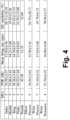
- ISI variability was the average motor unit ISI divided by the ISI standard deviation for each motor unit. This value was then averaged across all motor units. The results are presented in the "ISI variability (%)" column of the table of FIGURE 4 .
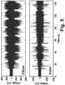
- FIGURE 5 shows the band-pass filtered EMG signal on a single channels for elbow flexion and extension (top plot of FIGURE 5 ) and index flexion and extension (bottom plot of FIGURE 5 ).
- the movement periods are easily discriminated from rest during the elbow trial while attempted movements of the index finger are difficult to distinguish visually.
- this myoelectric activity with minimal post-processing, was robust enough to allow for successful discrimination of all five fingers during attempted flexion and extension movements. It should be noted that the subject attempted the motions for which EMG activity are reported in FIGURE 5 without generating detectable motion.
- the classification results are shown in FIGURE 6 , where classification of five digit tasks was performed using multiple linear regression with leave-one-out cross-validation used to classify attempted movements of the five digits during eight movement periods per digit.
- the accuracy of each decoded movement was calculated as the proportion of samples classified correctly out of all samples of the movement. Thumb finger trials were classified with the highest accuracy (88%), followed by middle (76%), index (67%), pinky (65%), and, lastly, ring (33%). The digits most often confused were ring and pinky and index and middle.
- the "MUs" column reports the number of identified motor units (MUs) during the individual digit tasks and joint movements.
- PNR pulse-to-noise ratio
- pps mean firing rate
- ISI variability %
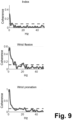
- FIGURES 7 , 8 , and 9 present extracted MU activity in graphical formats, and show the extracted motor unit spike instants for two representative movement trials, index flexion and extension and elbow flexion and extension. Interestingly, some motor units showed a tonic activity whilst other were activated in bursts during the dynamic tasks, reflecting common strategies of joint movements as in intact individuals. Moreover, The average discharge rate and the interspike intervals (see table of FIGURE 4 ) showed similar values as those that have been observed in healthy subjects.
- more complex hand movements may be similarly classified, such as multiple grasp types, and proportional control of those movements with a comparison of input features from both the composite EMG signal and the decomposed MU activity.
- a higher number of identified MU units with higher discharge rates is expected to correspond to a higher force (albeit possibly with coarser control) intended action; whereas, a smaller number of MU units with lower discharge rates is expected to correspond to a more precisely controlled, lower force intended action
- intracortical activity is recorded, e.g. via an intracortical electrode or electrodes array
- the described experiments demonstrate that myoelectric activity can be detected and decoded from the forearm of a person with tetraplegia without motion of the hand or fingers, providing a robust control signal for neuroprosthetics and other assistive technologies.
- This EMG activity can be decomposed into individual MUs, which can provide insight into spinal network reorganization and recovery following neurological injuries, such as SCI and stroke.
Landscapes
- Health & Medical Sciences (AREA)
- Engineering & Computer Science (AREA)
- Life Sciences & Earth Sciences (AREA)
- Public Health (AREA)
- Biomedical Technology (AREA)
- General Health & Medical Sciences (AREA)
- Medical Informatics (AREA)
- Animal Behavior & Ethology (AREA)
- Veterinary Medicine (AREA)
- Heart & Thoracic Surgery (AREA)
- Biophysics (AREA)
- Pathology (AREA)
- Physics & Mathematics (AREA)
- Primary Health Care (AREA)
- Epidemiology (AREA)
- Surgery (AREA)
- Molecular Biology (AREA)
- Nuclear Medicine, Radiotherapy & Molecular Imaging (AREA)
- Radiology & Medical Imaging (AREA)
- Physiology (AREA)
- Artificial Intelligence (AREA)
- Physical Education & Sports Medicine (AREA)
- Business, Economics & Management (AREA)
- General Business, Economics & Management (AREA)
- Cardiology (AREA)
- Vascular Medicine (AREA)
- Databases & Information Systems (AREA)
- Data Mining & Analysis (AREA)
- Oral & Maxillofacial Surgery (AREA)
- Signal Processing (AREA)
- Psychiatry (AREA)
- Computer Vision & Pattern Recognition (AREA)
- Transplantation (AREA)
- Mathematical Physics (AREA)
- Fuzzy Systems (AREA)
- Evolutionary Computation (AREA)
- Dentistry (AREA)
- Reproductive Health (AREA)
- Neurology (AREA)
- Orthopedic Medicine & Surgery (AREA)
Claims (15)
- Elektromyographie-Vorrichtung, umfassend:ein tragbares Elektrodenkleidungsstück (10), das Elektroden (12) enthält, die für einen Kontakt mit der Haut, wenn das tragbare Elektrodenkleidungsstück (10 getragen wird, angeordnet sind,eine elektronische Steuereinrichtung (20), die operativ mit den Elektroden (12) verbunden ist und programmiert ist zum Durchführen eines Verfahrens, das die folgenden Schritte umfasst:Empfangen von Oberflächen-Elektromyographie (EMG)-Signalen (30) über die Elektroden (12),Extrahieren eines oder mehrerer Motoreinheit (Motor Unit bzw. MU)-Aktionspotentiale aus den Oberflächen-EMG-Signalen (30), wobei jede MU ein Motorneuron und durch das Motorneuron innervierte Skelettmuskelfasern umfasst und jedes MU-Aktionspotential das durch das Motorneuron der entsprechenden MU getragene elektrische Signal umfasst, undwenigstens eines der Folgenden:(i) Identifizieren einer gewünschten Bewegung (50) basierend wenigstens auf Merkmalen, die das eine oder die mehreren extrahierten MU-Aktionspotentiale wiedergeben, und Zuführen einer funktionalen elektrischen Stimulation (FES), die effektiv ist für das Implementieren der gewünschten Bewegung (50), über die Elektroden (12) des tragbaren Elektrodenkleidungsstücks (10), oder(ii) Erzeugen eines Performanzberichts (54) basierend wenigstens auf einem Vergleich von Merkmalen, die das eine oder die mehreren extrahierten MU-Aktionspotentiale wiedergeben, und von Merkmalen, die erwartete und/oder grundlegende MU-Aktionspotentiale für eine bekannte gewünschte Bewegung (50) wiedergeben.
- Elektromyographie-Vorrichtung nach Anspruch 1, wobei das Extrahieren eines oder mehrerer MU-Aktionspotentiale aus den Oberflächen-EMG-Signalen (30) das Durchführen einer konvolutionellen Kernel-Kompensation (Convolutional Kernel Compensation CKC)-Dekompensation (40) auf den Oberflächen-EMG-Signalen (30) für das Erzeugen des einen oder der mehreren MU-Aktivierungspotentiale umfasst.
- Elektromyographie-Vorrichtung nach einem der Ansprüche 1-2, wobei das Extrahieren des einen oder der mehreren MU-Aktionspotentiale aus den Oberflächen-EMG-Signalen (30) weiterhin das Berechnen eines oder mehrerer Merkmale jedes MU-Aktionspotentials umfasst.
- Elektromyographie-Vorrichtung nach Anspruch 3, wobei:
das Extrahieren eines oder mehrerer MU-Aktionspotentiale aus den Oberflächen-EMG-Signalen (30) das Erhalten nur derjenigen des einen oder der mehreren MU-Aktionspotentiale, die ein zuverlässiges Entladungsmusterwie durch eines oder mehrere der Merkmale angegeben aufweisen, umfasst. - Elektromyographie-Vorrichtung nach einem der Ansprüche 1 bis 4, wobei:das durch die elektronische Steuereinrichtung (20) durchgeführte Verfahren weiterhin das Identifizieren wenigstens eines Bereichs mit einer hohen neuronalen Aktivität (36) basierend auf den Oberflächen-EMG-Signalen (30) umfasst,wobei die gewünschte Bewegung (50) basierend auf dem wenigstens einen Bereich mit einer hohen neuronalen Aktivität (36) und den Merkmalen, die das eine oder die mehreren extrahierten MU-Aktionspotentiale wiedergeben, identifiziert wird.
- Elektromyographie-Vorrichtung nach Anspruch 5, wobei der Klassifizierer auf Merkmale angewendet wird, die wenigstens eine oder mehrere durch die Hauptsächliche-Komponenten-Analyse (Principal Component Analysis bzw. PCA) extrahierte hauptsächliche Komponenten der Oberflächen-EMG-Signale (30) enthalten.
- Elektromyographie-Vorrichtung nach einem der Ansprüche 5-6, wobei das Identifizieren der gewünschten Bewegung (50) das Anwenden einer oder mehrerer Klassifizierer, die spezifisch für den identifizierten wenigstens einen Bereich mit einer hohen neuronalen Aktivität (36) sind, auf die Merkmale, die wenigstens die Merkmale, die das eine oder die mehreren extrahierten MU-Aktionspotentiale wiedergeben, für das Identifizieren der gewünschten Bewegung (50) umfasst.
- Elektromyographie-Vorrichtung nach Anspruch 7, wobei die Merkmale, die das eine oder die mehreren extrahierten MU-Aktionspotentiale wiedergeben, eine Anzahl von MU-Aktivierungspotentialen und Entladungsraten für die MU-Aktivierungspotentiale enthalten.
- Elektromyographie-Vorrichtung nach einem der Ansprüche 1-8, wobei:
das durch die elektronische Steuereinrichtung (20) durchgeführte Verfahren (ii) das Erzeugen eines Performanzberichts (54) basierend wenigstens auf einem Vergleich von Merkmalen, die das eine oder die mehreren extrahierten MU-Aktionspotentiale wiedergeben, und von Merkmalen, die erwartete und/oder grundlegende MU-Aktionspotentiale für eine bekannte gewünschte Bewegung (50) wiedergeben, umfasst. - Elektromyographie-Vorrichtung nach einem der Ansprüche 1-9, wobei das tragbare Elektrodenkleidungsstück (10) wenigstens 50 Elektroden (12) umfasst, die für einen Kontakt mit der Haut, wenn das tragbare Elektrodenkleidungsstück (10) getragen wird, angeordnet sind, und/oder
wobei das tragbare Elektrodenkleidungsstück (10) ein tragbarer Elektrodenärmel (10) ist. - Elektromyographie-Vorrichtung nach Anspruch 1, wobei:
das durch die elektronische Steuereinrichtung (20) durchgeführte Verfahren (i) das Identifizieren einer gewünschten Bewegung (50) basierend wenigstens auf Merkmalen, die ein oder mehrere extrahierte MU-Aktionspotentiale wiedergeben, und das Zuführen einer funktionellen elektrischen Stimulation (FES), die effektiv ist für das Implementieren der gewünschten Bewegung (50), über die Elektroden (12) des tragbaren Elektrodenkleidungsstücks (10) umfasst. - Elektromyographie-Vorrichtung nach Anspruch 11, wobei das Extrahieren eines oder mehrerer MU-Aktionspotentiale aus den Oberflächen-EMG-Signalen (30) umfasst:
Berechnen eines oder mehrerer Merkmale jedes MU-Aktionspotentials. - Elektromyographie-Vorrichtung nach Anspruch 12, wobei das eine oder die mehreren für jedes MU-Aktionspotential berechneten Merkmale eine oder mehrere Eigenschaften der Gruppe umfassen, die aus einer Interpuls-Intervall (ISI)-Variabilität und einem Puls-zu-Rauschen-Verhältnis (PNR) besteht.
- Elektromyographie-Vorrichtung nach einem der Ansprüche 11-13, wobei das Identifizieren der gewünschten Bewegung (50) weiterhin auf Merkmalen basiert, die eine oder mehrere durch eine Hauptsächliche-Komponenten-Analyse (Principal Component Analysis bzw. PCA) (34) extrahierte hauptsächliche Komponenten der Oberflächen-EMG-Signale (30) umfassen, und/oderwobei das Identifizieren der gewünschten Bewegung (50) das Anwenden eines oder mehrerer Klassifizierer, die spezifisch für einen basierend auf den EMG-Signalen (30) identifizierten Bereich mit einer hohen neuronalen Aktivität (36) sind, umfasst, und/oder wobei die Merkmale, die das eine oder die mehreren extrahierten MU-Aktionspotentiale wiedergeben, eine Anzahl des einen oder der mehreren extrahierten MU-Aktionspotentiale und Entladungsraten für das eine oder die mehreren MU-Aktivierungspotentiale enthält, und/oderwobei das tragbare Elektrodenkleidungsstück (10) wenigstens 50 Elektroden (12) umfasst, die für einen Kontakt mit der Haut, wenn das tragbare Elektrodenkleidungsstück (10) getragen wird, angeordnet sind,wobei die Elektromyographie-Vorrichtung keine Gehirn-Computer-Schnittstelle (Brain-Computer interface bzw. BCI) umfasst.
- Elektromyographie-Verfahren, umfassend:Empfangen von Oberflächen-Elektromyographie (EMG)-Signalen (30) über Elektroden 12 eines tragbaren Elektrodenkleidungsstücks (10), undVerwenden eines elektronischen Prozessors (22) zum:Extrahieren eines oder mehrerer Motoreinheit (Motor Unit bzw. MU)-Aktionspotentiale aus den Oberflächen-EMG-Signalen (30), wobei jede MU ein Motorneuron und durch das Motorneuron innervierte Skelettmuskelfasern umfasst und jedes MU-Aktionspotential das durch das Motorneuron der entsprechenden MU getragene elektrische Signal umfasst, undeines der Folgenden:(i) Identifizieren einer gewünschten Bewegung (50) basierend wenigstens auf dem einen oder den mehreren extrahierten MU-Aktionspotentialen, und Zuführen einer funktionalen elektrischen Stimulation (FES), die effektiv ist für das Implementieren der gewünschten Bewegung (50), über die Elektroden (12) des tragbaren Elektrodenkleidungsstücks (10), oder(ii) Erzeugen eines Performanzberichts (54) basierend wenigstens auf einem Vergleich des einen oder der mehreren extrahierten MU-Aktionspotentiale und erwarteten und/oder grundlegenden MU-Aktionspotentialen für eine bekannte gewünschte Bewegung (50).
Applications Claiming Priority (2)
| Application Number | Priority Date | Filing Date | Title |
|---|---|---|---|
| US201962868317P | 2019-06-28 | 2019-06-28 | |
| PCT/US2020/039809 WO2020264286A1 (en) | 2019-06-28 | 2020-06-26 | Control of functional electrical stimulation using motor unit action potentials |
Publications (2)
| Publication Number | Publication Date |
|---|---|
| EP3990102A1 EP3990102A1 (de) | 2022-05-04 |
| EP3990102B1 true EP3990102B1 (de) | 2024-10-09 |
Family
ID=71728896
Family Applications (1)
| Application Number | Title | Priority Date | Filing Date |
|---|---|---|---|
| EP20743425.9A Active EP3990102B1 (de) | 2019-06-28 | 2020-06-26 | Steuerung der funktionellen elektrischen stimulation mit aktionspotentialen einer motoreinheit |
Country Status (5)
| Country | Link |
|---|---|
| US (1) | US11524160B2 (de) |
| EP (1) | EP3990102B1 (de) |
| CA (1) | CA3144966A1 (de) |
| IL (1) | IL289347B2 (de) |
| WO (1) | WO2020264286A1 (de) |
Families Citing this family (14)
| Publication number | Priority date | Publication date | Assignee | Title |
|---|---|---|---|---|
| WO2021242775A1 (en) * | 2020-05-27 | 2021-12-02 | The Johns Hopkins University | System and method for implantable muscle interface |
| WO2021248010A1 (en) | 2020-06-06 | 2021-12-09 | Battelle Memorial Institute | High-definition electrical stimulation for enhanced spatial awareness and target alignment in weapon aiming applications |
| EP4162346A1 (de) | 2020-06-06 | 2023-04-12 | Battelle Memorial Institute | Nichtverbales kommunikationsfunk- und nichtverbales kommunikationssystem mit mehreren nichtverbalen kommunikationsfunkgeräten |
| WO2021248007A1 (en) | 2020-06-06 | 2021-12-09 | Battelle Memorial Institute | Portable and wearable hand-grasp neuro-orthosis |
| US20230263421A1 (en) * | 2020-07-30 | 2023-08-24 | Battelle Memorial Institute | Electrical impedance tomography based method for functional electrical stimulation and electromyography garment |
| KR102740215B1 (ko) * | 2021-05-07 | 2024-12-10 | 주식회사 엑소시스템즈 | 근전도 신호를 사용하는 기능성 전기자극 생성 시스템 |
| US12172011B2 (en) | 2021-08-09 | 2024-12-24 | Cionic, Inc. | Adaptive stimulation array for motor control |
| US11931571B2 (en) | 2021-08-09 | 2024-03-19 | Cionic, Inc. | Adaptive stimulation array calibration |
| WO2023018539A1 (en) * | 2021-08-09 | 2023-02-16 | Cionic, Inc. | Adaptive stimulation array for motor control |
| US12555414B2 (en) | 2021-08-25 | 2026-02-17 | Battelle Memorial Institute | Neuromuscular electrical stimulation controlled by computer vision |
| US20230062326A1 (en) | 2021-08-25 | 2023-03-02 | Battelle Memorial Institute | Guided rehabilitation to relearn motor control using neuromuscular electrical stimulation |
| US12589240B2 (en) * | 2022-03-11 | 2026-03-31 | AxioBionics LLC | Muscle stimulation system |
| US20240225482A9 (en) * | 2022-10-25 | 2024-07-11 | Battelle Memorial Institute | Lower limb sleeve for detecting and overcoming freeze of gait |
| WO2025089740A1 (ko) * | 2023-10-27 | 2025-05-01 | 주식회사 엑소시스템즈 | 신경근육계 신호 분석을 수행하는 방법 및 장치 |
Family Cites Families (7)
| Publication number | Priority date | Publication date | Assignee | Title |
|---|---|---|---|---|
| US9155487B2 (en) * | 2005-12-21 | 2015-10-13 | Michael Linderman | Method and apparatus for biometric analysis using EEG and EMG signals |
| EP2241246A1 (de) * | 2009-04-14 | 2010-10-20 | Koninklijke Philips Electronics N.V. | Verwendung von Erkennung der Muskelspannung zur Lokalisierung einer Stelle auf der Haut zur Messung eines Analyten |
| EP4201469B1 (de) | 2012-12-05 | 2026-01-21 | Battelle Memorial Institute | Manschette für neuromuskulare stimulation |
| US9884179B2 (en) | 2012-12-05 | 2018-02-06 | Bbattelle Memorial Institute | Neural sleeve for neuromuscular stimulation, sensing and recording |
| EP3782696B1 (de) * | 2015-06-02 | 2022-12-28 | Battelle Memorial Institute | Systeme zur neuronalen überbrückung des nervensystems |
| US12151101B2 (en) * | 2015-06-02 | 2024-11-26 | Battelle Memorial Institute | Non-invasive eye-tracking control of neuromuscular stimulation system |
| US20170312576A1 (en) | 2016-04-02 | 2017-11-02 | Senthil Natarajan | Wearable Physiological Sensor System for Training and Therapeutic Purposes |
-
2020
- 2020-06-26 EP EP20743425.9A patent/EP3990102B1/de active Active
- 2020-06-26 CA CA3144966A patent/CA3144966A1/en active Pending
- 2020-06-26 US US16/913,706 patent/US11524160B2/en active Active
- 2020-06-26 WO PCT/US2020/039809 patent/WO2020264286A1/en not_active Ceased
- 2020-06-26 IL IL289347A patent/IL289347B2/en unknown
Also Published As
| Publication number | Publication date |
|---|---|
| IL289347B1 (en) | 2025-02-01 |
| US20200406035A1 (en) | 2020-12-31 |
| CA3144966A1 (en) | 2020-12-30 |
| US11524160B2 (en) | 2022-12-13 |
| BR112021026583A2 (pt) | 2022-05-24 |
| IL289347A (en) | 2022-02-01 |
| WO2020264286A1 (en) | 2020-12-30 |
| EP3990102A1 (de) | 2022-05-04 |
| IL289347B2 (en) | 2025-06-01 |
Similar Documents
| Publication | Publication Date | Title |
|---|---|---|
| EP3990102B1 (de) | Steuerung der funktionellen elektrischen stimulation mit aktionspotentialen einer motoreinheit | |
| Yang et al. | EEG-and EMG-driven poststroke rehabilitation: A review | |
| Gerloff et al. | The role of the human motor cortex in the control of complex and simple finger movement sequences. | |
| Bai et al. | A high performance sensorimotor beta rhythm-based brain–computer interface associated with human natural motor behavior | |
| Farrell | A comparison of the effects of electrode implantation and targeting on pattern classification accuracy for prosthesis control | |
| US20230065510A1 (en) | Control of functional electrical stimulation using motor unit action potentials | |
| US6936012B2 (en) | Method and apparatus for identifying constituent signal components from a plurality of evoked physiological composite signals | |
| Rak et al. | Brain-computer interface as measurement and control system the review paper | |
| Qian et al. | A motor imagery-based online interactive brain-controlled switch: paradigm development and preliminary test | |
| WO2016033686A1 (en) | Method and system for brain activity signal-based treatment and/or control of user devices | |
| Kæseler et al. | Feature and classification analysis for detection and classification of tongue movements from single-trial pre-movement EEG | |
| Tang et al. | Bayesian spatial filters for source signal extraction: A study in the peripheral nerve | |
| IL296879A (en) | System and method for mapping muscle activation | |
| Ting et al. | A wearable neural interface for detecting and decoding attempted hand movements in a person with tetraplegia | |
| Alzahrani et al. | A comparison of conventional and tri-polar EEG electrodes for decoding real and imaginary finger movements from one hand | |
| Xia et al. | Extracting individual muscle drive and activity from high-density surface electromyography signals based on the center of gravity of motor unit | |
| Khan et al. | Brain–computer interface for single-trial EEG classification for wrist movement imagery using spatial filtering in the gamma band | |
| Kæseler et al. | Detection and classification of tongue movements from single-trial EEG | |
| US20250359799A1 (en) | Electromyography devices and methods with filtering of electromyography signals | |
| Zhou et al. | Surface electromyogram analysis of the direction of isometric torque generation by the first dorsal interosseous muscle | |
| Gevins | Quantitative human neurophysiology | |
| Bogdanov et al. | Development of a neurodevice with a biological feedback for compensating for lost motor functions | |
| BR112021026583B1 (pt) | Dispositivo de eletromiografia e método de eletromiografia | |
| Irimia et al. | Improved method to perform FES&BCI based rehabilitation | |
| Foldes et al. | Stability of MEG for real-time neurofeedback |
Legal Events
| Date | Code | Title | Description |
|---|---|---|---|
| STAA | Information on the status of an ep patent application or granted ep patent |
Free format text: STATUS: UNKNOWN |
|
| STAA | Information on the status of an ep patent application or granted ep patent |
Free format text: STATUS: THE INTERNATIONAL PUBLICATION HAS BEEN MADE |
|
| PUAI | Public reference made under article 153(3) epc to a published international application that has entered the european phase |
Free format text: ORIGINAL CODE: 0009012 |
|
| STAA | Information on the status of an ep patent application or granted ep patent |
Free format text: STATUS: REQUEST FOR EXAMINATION WAS MADE |
|
| 17P | Request for examination filed |
Effective date: 20220113 |
|
| AK | Designated contracting states |
Kind code of ref document: A1 Designated state(s): AL AT BE BG CH CY CZ DE DK EE ES FI FR GB GR HR HU IE IS IT LI LT LU LV MC MK MT NL NO PL PT RO RS SE SI SK SM TR |
|
| DAV | Request for validation of the european patent (deleted) | ||
| DAX | Request for extension of the european patent (deleted) | ||
| STAA | Information on the status of an ep patent application or granted ep patent |
Free format text: STATUS: EXAMINATION IS IN PROGRESS |
|
| 17Q | First examination report despatched |
Effective date: 20230309 |
|
| P01 | Opt-out of the competence of the unified patent court (upc) registered |
Effective date: 20230530 |
|
| GRAP | Despatch of communication of intention to grant a patent |
Free format text: ORIGINAL CODE: EPIDOSNIGR1 |
|
| STAA | Information on the status of an ep patent application or granted ep patent |
Free format text: STATUS: GRANT OF PATENT IS INTENDED |
|
| RIC1 | Information provided on ipc code assigned before grant |
Ipc: A61N 1/36 20060101ALI20231206BHEP Ipc: A61F 4/00 20060101ALI20231206BHEP Ipc: A61F 2/72 20060101ALI20231206BHEP Ipc: A61B 5/11 20060101ALI20231206BHEP Ipc: A61B 5/375 20210101ALI20231206BHEP Ipc: A61N 1/05 20060101AFI20231206BHEP |
|
| INTG | Intention to grant announced |
Effective date: 20240103 |
|
| GRAJ | Information related to disapproval of communication of intention to grant by the applicant or resumption of examination proceedings by the epo deleted |
Free format text: ORIGINAL CODE: EPIDOSDIGR1 |
|
| STAA | Information on the status of an ep patent application or granted ep patent |
Free format text: STATUS: EXAMINATION IS IN PROGRESS |
|
| INTC | Intention to grant announced (deleted) | ||
| GRAP | Despatch of communication of intention to grant a patent |
Free format text: ORIGINAL CODE: EPIDOSNIGR1 |
|
| STAA | Information on the status of an ep patent application or granted ep patent |
Free format text: STATUS: GRANT OF PATENT IS INTENDED |
|
| INTG | Intention to grant announced |
Effective date: 20240528 |
|
| GRAS | Grant fee paid |
Free format text: ORIGINAL CODE: EPIDOSNIGR3 |
|
| GRAA | (expected) grant |
Free format text: ORIGINAL CODE: 0009210 |
|
| STAA | Information on the status of an ep patent application or granted ep patent |
Free format text: STATUS: THE PATENT HAS BEEN GRANTED |
|
| AK | Designated contracting states |
Kind code of ref document: B1 Designated state(s): AL AT BE BG CH CY CZ DE DK EE ES FI FR GB GR HR HU IE IS IT LI LT LU LV MC MK MT NL NO PL PT RO RS SE SI SK SM TR |
|
| REG | Reference to a national code |
Ref country code: CH Ref legal event code: EP |
|
| REG | Reference to a national code |
Ref country code: DE Ref legal event code: R096 Ref document number: 602020039098 Country of ref document: DE |
|
| REG | Reference to a national code |
Ref country code: IE Ref legal event code: FG4D |
|
| REG | Reference to a national code |
Ref country code: LT Ref legal event code: MG9D |
|
| REG | Reference to a national code |
Ref country code: NL Ref legal event code: MP Effective date: 20241009 |
|
| REG | Reference to a national code |
Ref country code: AT Ref legal event code: MK05 Ref document number: 1729928 Country of ref document: AT Kind code of ref document: T Effective date: 20241009 |
|
| PG25 | Lapsed in a contracting state [announced via postgrant information from national office to epo] |
Ref country code: NL Free format text: LAPSE BECAUSE OF FAILURE TO SUBMIT A TRANSLATION OF THE DESCRIPTION OR TO PAY THE FEE WITHIN THE PRESCRIBED TIME-LIMIT Effective date: 20241009 |
|
| PG25 | Lapsed in a contracting state [announced via postgrant information from national office to epo] |
Ref country code: NL Free format text: LAPSE BECAUSE OF FAILURE TO SUBMIT A TRANSLATION OF THE DESCRIPTION OR TO PAY THE FEE WITHIN THE PRESCRIBED TIME-LIMIT Effective date: 20241009 |
|
| PG25 | Lapsed in a contracting state [announced via postgrant information from national office to epo] |
Ref country code: IS Free format text: LAPSE BECAUSE OF FAILURE TO SUBMIT A TRANSLATION OF THE DESCRIPTION OR TO PAY THE FEE WITHIN THE PRESCRIBED TIME-LIMIT Effective date: 20250209 Ref country code: PT Free format text: LAPSE BECAUSE OF FAILURE TO SUBMIT A TRANSLATION OF THE DESCRIPTION OR TO PAY THE FEE WITHIN THE PRESCRIBED TIME-LIMIT Effective date: 20250210 Ref country code: HR Free format text: LAPSE BECAUSE OF FAILURE TO SUBMIT A TRANSLATION OF THE DESCRIPTION OR TO PAY THE FEE WITHIN THE PRESCRIBED TIME-LIMIT Effective date: 20241009 |
|
| PG25 | Lapsed in a contracting state [announced via postgrant information from national office to epo] |
Ref country code: FI Free format text: LAPSE BECAUSE OF FAILURE TO SUBMIT A TRANSLATION OF THE DESCRIPTION OR TO PAY THE FEE WITHIN THE PRESCRIBED TIME-LIMIT Effective date: 20241009 |
|
| PG25 | Lapsed in a contracting state [announced via postgrant information from national office to epo] |
Ref country code: BG Free format text: LAPSE BECAUSE OF FAILURE TO SUBMIT A TRANSLATION OF THE DESCRIPTION OR TO PAY THE FEE WITHIN THE PRESCRIBED TIME-LIMIT Effective date: 20241009 |
|
| PG25 | Lapsed in a contracting state [announced via postgrant information from national office to epo] |
Ref country code: ES Free format text: LAPSE BECAUSE OF FAILURE TO SUBMIT A TRANSLATION OF THE DESCRIPTION OR TO PAY THE FEE WITHIN THE PRESCRIBED TIME-LIMIT Effective date: 20241009 |
|
| PG25 | Lapsed in a contracting state [announced via postgrant information from national office to epo] |
Ref country code: NO Free format text: LAPSE BECAUSE OF FAILURE TO SUBMIT A TRANSLATION OF THE DESCRIPTION OR TO PAY THE FEE WITHIN THE PRESCRIBED TIME-LIMIT Effective date: 20250109 |
|
| PG25 | Lapsed in a contracting state [announced via postgrant information from national office to epo] |
Ref country code: LV Free format text: LAPSE BECAUSE OF FAILURE TO SUBMIT A TRANSLATION OF THE DESCRIPTION OR TO PAY THE FEE WITHIN THE PRESCRIBED TIME-LIMIT Effective date: 20241009 Ref country code: GR Free format text: LAPSE BECAUSE OF FAILURE TO SUBMIT A TRANSLATION OF THE DESCRIPTION OR TO PAY THE FEE WITHIN THE PRESCRIBED TIME-LIMIT Effective date: 20250110 Ref country code: AT Free format text: LAPSE BECAUSE OF FAILURE TO SUBMIT A TRANSLATION OF THE DESCRIPTION OR TO PAY THE FEE WITHIN THE PRESCRIBED TIME-LIMIT Effective date: 20241009 |
|
| PG25 | Lapsed in a contracting state [announced via postgrant information from national office to epo] |
Ref country code: PL Free format text: LAPSE BECAUSE OF FAILURE TO SUBMIT A TRANSLATION OF THE DESCRIPTION OR TO PAY THE FEE WITHIN THE PRESCRIBED TIME-LIMIT Effective date: 20241009 |
|
| PG25 | Lapsed in a contracting state [announced via postgrant information from national office to epo] |
Ref country code: RS Free format text: LAPSE BECAUSE OF FAILURE TO SUBMIT A TRANSLATION OF THE DESCRIPTION OR TO PAY THE FEE WITHIN THE PRESCRIBED TIME-LIMIT Effective date: 20250109 |
|
| PG25 | Lapsed in a contracting state [announced via postgrant information from national office to epo] |
Ref country code: SM Free format text: LAPSE BECAUSE OF FAILURE TO SUBMIT A TRANSLATION OF THE DESCRIPTION OR TO PAY THE FEE WITHIN THE PRESCRIBED TIME-LIMIT Effective date: 20241009 |
|
| PGFP | Annual fee paid to national office [announced via postgrant information from national office to epo] |
Ref country code: DE Payment date: 20250509 Year of fee payment: 6 |
|
| PG25 | Lapsed in a contracting state [announced via postgrant information from national office to epo] |
Ref country code: DK Free format text: LAPSE BECAUSE OF FAILURE TO SUBMIT A TRANSLATION OF THE DESCRIPTION OR TO PAY THE FEE WITHIN THE PRESCRIBED TIME-LIMIT Effective date: 20241009 |
|
| PGFP | Annual fee paid to national office [announced via postgrant information from national office to epo] |
Ref country code: GB Payment date: 20250508 Year of fee payment: 6 |
|
| REG | Reference to a national code |
Ref country code: DE Ref legal event code: R097 Ref document number: 602020039098 Country of ref document: DE |
|
| PG25 | Lapsed in a contracting state [announced via postgrant information from national office to epo] |
Ref country code: EE Free format text: LAPSE BECAUSE OF FAILURE TO SUBMIT A TRANSLATION OF THE DESCRIPTION OR TO PAY THE FEE WITHIN THE PRESCRIBED TIME-LIMIT Effective date: 20241009 |
|
| PGFP | Annual fee paid to national office [announced via postgrant information from national office to epo] |
Ref country code: FR Payment date: 20250512 Year of fee payment: 6 |
|
| PG25 | Lapsed in a contracting state [announced via postgrant information from national office to epo] |
Ref country code: RO Free format text: LAPSE BECAUSE OF FAILURE TO SUBMIT A TRANSLATION OF THE DESCRIPTION OR TO PAY THE FEE WITHIN THE PRESCRIBED TIME-LIMIT Effective date: 20241009 |
|
| PG25 | Lapsed in a contracting state [announced via postgrant information from national office to epo] |
Ref country code: SK Free format text: LAPSE BECAUSE OF FAILURE TO SUBMIT A TRANSLATION OF THE DESCRIPTION OR TO PAY THE FEE WITHIN THE PRESCRIBED TIME-LIMIT Effective date: 20241009 |
|
| PG25 | Lapsed in a contracting state [announced via postgrant information from national office to epo] |
Ref country code: CZ Free format text: LAPSE BECAUSE OF FAILURE TO SUBMIT A TRANSLATION OF THE DESCRIPTION OR TO PAY THE FEE WITHIN THE PRESCRIBED TIME-LIMIT Effective date: 20241009 |
|
| PG25 | Lapsed in a contracting state [announced via postgrant information from national office to epo] |
Ref country code: IT Free format text: LAPSE BECAUSE OF FAILURE TO SUBMIT A TRANSLATION OF THE DESCRIPTION OR TO PAY THE FEE WITHIN THE PRESCRIBED TIME-LIMIT Effective date: 20241009 |
|
| PLBE | No opposition filed within time limit |
Free format text: ORIGINAL CODE: 0009261 |
|
| STAA | Information on the status of an ep patent application or granted ep patent |
Free format text: STATUS: NO OPPOSITION FILED WITHIN TIME LIMIT |
|
| PG25 | Lapsed in a contracting state [announced via postgrant information from national office to epo] |
Ref country code: SE Free format text: LAPSE BECAUSE OF FAILURE TO SUBMIT A TRANSLATION OF THE DESCRIPTION OR TO PAY THE FEE WITHIN THE PRESCRIBED TIME-LIMIT Effective date: 20241009 |
|
| 26N | No opposition filed |
Effective date: 20250710 |
|
| REG | Reference to a national code |
Ref country code: CH Ref legal event code: H13 Free format text: ST27 STATUS EVENT CODE: U-0-0-H10-H13 (AS PROVIDED BY THE NATIONAL OFFICE) Effective date: 20260127 |
|
| PG25 | Lapsed in a contracting state [announced via postgrant information from national office to epo] |
Ref country code: MC Free format text: LAPSE BECAUSE OF FAILURE TO SUBMIT A TRANSLATION OF THE DESCRIPTION OR TO PAY THE FEE WITHIN THE PRESCRIBED TIME-LIMIT Effective date: 20241009 |
|
| PG25 | Lapsed in a contracting state [announced via postgrant information from national office to epo] |
Ref country code: LU Free format text: LAPSE BECAUSE OF NON-PAYMENT OF DUE FEES Effective date: 20250626 |
|
| REG | Reference to a national code |
Ref country code: BE Ref legal event code: MM Effective date: 20250630 |
|
| PG25 | Lapsed in a contracting state [announced via postgrant information from national office to epo] |
Ref country code: IE Free format text: LAPSE BECAUSE OF NON-PAYMENT OF DUE FEES Effective date: 20250626 |
|
| PG25 | Lapsed in a contracting state [announced via postgrant information from national office to epo] |
Ref country code: BE Free format text: LAPSE BECAUSE OF NON-PAYMENT OF DUE FEES Effective date: 20250630 |
|
| PG25 | Lapsed in a contracting state [announced via postgrant information from national office to epo] |
Ref country code: CH Free format text: LAPSE BECAUSE OF NON-PAYMENT OF DUE FEES Effective date: 20250630 |