EP3990212B1 - Porte-buse pour tête de traitement laser d'un système de traitement laser ; procédé d'engagement et de désengagement d'une buse laser par rapport à un porte-buse d'une tête de traitement laser d'un système de traitement laser - Google Patents
Porte-buse pour tête de traitement laser d'un système de traitement laser ; procédé d'engagement et de désengagement d'une buse laser par rapport à un porte-buse d'une tête de traitement laser d'un système de traitement laser Download PDFInfo
- Publication number
- EP3990212B1 EP3990212B1 EP20742997.8A EP20742997A EP3990212B1 EP 3990212 B1 EP3990212 B1 EP 3990212B1 EP 20742997 A EP20742997 A EP 20742997A EP 3990212 B1 EP3990212 B1 EP 3990212B1
- Authority
- EP
- European Patent Office
- Prior art keywords
- pawls
- nozzle
- hollow body
- pawl
- laser
- Prior art date
- Legal status (The legal status is an assumption and is not a legal conclusion. Google has not performed a legal analysis and makes no representation as to the accuracy of the status listed.)
- Active
Links
Images



Classifications
-
- B—PERFORMING OPERATIONS; TRANSPORTING
- B23—MACHINE TOOLS; METAL-WORKING NOT OTHERWISE PROVIDED FOR
- B23K—SOLDERING OR UNSOLDERING; WELDING; CLADDING OR PLATING BY SOLDERING OR WELDING; CUTTING BY APPLYING HEAT LOCALLY, e.g. FLAME CUTTING; WORKING BY LASER BEAM
- B23K26/00—Working by laser beam, e.g. welding, cutting or boring
- B23K26/36—Removing material
- B23K26/38—Removing material by boring or cutting
-
- B—PERFORMING OPERATIONS; TRANSPORTING
- B23—MACHINE TOOLS; METAL-WORKING NOT OTHERWISE PROVIDED FOR
- B23K—SOLDERING OR UNSOLDERING; WELDING; CLADDING OR PLATING BY SOLDERING OR WELDING; CUTTING BY APPLYING HEAT LOCALLY, e.g. FLAME CUTTING; WORKING BY LASER BEAM
- B23K37/00—Auxiliary devices or processes, not specially adapted for a procedure covered by only one of the other main groups of this subclass
- B23K37/02—Carriages for supporting the welding or cutting element
- B23K37/0241—Attachments between the welding or cutting element and the carriage
-
- B—PERFORMING OPERATIONS; TRANSPORTING
- B23—MACHINE TOOLS; METAL-WORKING NOT OTHERWISE PROVIDED FOR
- B23K—SOLDERING OR UNSOLDERING; WELDING; CLADDING OR PLATING BY SOLDERING OR WELDING; CUTTING BY APPLYING HEAT LOCALLY, e.g. FLAME CUTTING; WORKING BY LASER BEAM
- B23K26/00—Working by laser beam, e.g. welding, cutting or boring
- B23K26/14—Working by laser beam, e.g. welding, cutting or boring using a fluid stream, e.g. a jet of gas, in conjunction with the laser beam; Nozzles therefor
- B23K26/1462—Nozzles; Features related to nozzles
-
- B—PERFORMING OPERATIONS; TRANSPORTING
- B23—MACHINE TOOLS; METAL-WORKING NOT OTHERWISE PROVIDED FOR
- B23K—SOLDERING OR UNSOLDERING; WELDING; CLADDING OR PLATING BY SOLDERING OR WELDING; CUTTING BY APPLYING HEAT LOCALLY, e.g. FLAME CUTTING; WORKING BY LASER BEAM
- B23K26/00—Working by laser beam, e.g. welding, cutting or boring
- B23K26/14—Working by laser beam, e.g. welding, cutting or boring using a fluid stream, e.g. a jet of gas, in conjunction with the laser beam; Nozzles therefor
- B23K26/1462—Nozzles; Features related to nozzles
- B23K26/1482—Detachable nozzles, e.g. exchangeable or provided with breakaway lines
-
- B—PERFORMING OPERATIONS; TRANSPORTING
- B23—MACHINE TOOLS; METAL-WORKING NOT OTHERWISE PROVIDED FOR
- B23K—SOLDERING OR UNSOLDERING; WELDING; CLADDING OR PLATING BY SOLDERING OR WELDING; CUTTING BY APPLYING HEAT LOCALLY, e.g. FLAME CUTTING; WORKING BY LASER BEAM
- B23K26/00—Working by laser beam, e.g. welding, cutting or boring
- B23K26/70—Auxiliary operations or equipment
-
- B—PERFORMING OPERATIONS; TRANSPORTING
- B23—MACHINE TOOLS; METAL-WORKING NOT OTHERWISE PROVIDED FOR
- B23K—SOLDERING OR UNSOLDERING; WELDING; CLADDING OR PLATING BY SOLDERING OR WELDING; CUTTING BY APPLYING HEAT LOCALLY, e.g. FLAME CUTTING; WORKING BY LASER BEAM
- B23K26/00—Working by laser beam, e.g. welding, cutting or boring
- B23K26/70—Auxiliary operations or equipment
- B23K26/702—Auxiliary equipment
-
- B—PERFORMING OPERATIONS; TRANSPORTING
- B23—MACHINE TOOLS; METAL-WORKING NOT OTHERWISE PROVIDED FOR
- B23Q—DETAILS, COMPONENTS, OR ACCESSORIES FOR MACHINE TOOLS, e.g. ARRANGEMENTS FOR COPYING OR CONTROLLING; MACHINE TOOLS IN GENERAL CHARACTERISED BY THE CONSTRUCTION OF PARTICULAR DETAILS OR COMPONENTS; COMBINATIONS OR ASSOCIATIONS OF METAL-WORKING MACHINES, NOT DIRECTED TO A PARTICULAR RESULT
- B23Q3/00—Devices holding, supporting, or positioning work or tools, of a kind normally removable from the machine
- B23Q3/155—Arrangements for automatic insertion or removal of tools, e.g. combined with manual handling
- B23Q3/1556—Arrangements for automatic insertion or removal of tools, e.g. combined with manual handling of non-rotary tools
-
- F—MECHANICAL ENGINEERING; LIGHTING; HEATING; WEAPONS; BLASTING
- F16—ENGINEERING ELEMENTS AND UNITS; GENERAL MEASURES FOR PRODUCING AND MAINTAINING EFFECTIVE FUNCTIONING OF MACHINES OR INSTALLATIONS; THERMAL INSULATION IN GENERAL
- F16L—PIPES; JOINTS OR FITTINGS FOR PIPES; SUPPORTS FOR PIPES, CABLES OR PROTECTIVE TUBING; MEANS FOR THERMAL INSULATION IN GENERAL
- F16L37/00—Couplings of the quick-acting type
- F16L37/08—Couplings of the quick-acting type in which the connection between abutting or axially overlapping ends is maintained by locking members
- F16L37/12—Couplings of the quick-acting type in which the connection between abutting or axially overlapping ends is maintained by locking members using hooks, pawls, or other movable or insertable locking members
-
- H—ELECTRICITY
- H05—ELECTRIC TECHNIQUES NOT OTHERWISE PROVIDED FOR
- H05H—PLASMA TECHNIQUE; PRODUCTION OF ACCELERATED ELECTRICALLY-CHARGED PARTICLES OR OF NEUTRONS; PRODUCTION OR ACCELERATION OF NEUTRAL MOLECULAR OR ATOMIC BEAMS
- H05H1/00—Generating plasma; Handling plasma
- H05H1/24—Generating plasma
- H05H1/26—Plasma torches
- H05H1/32—Plasma torches using an arc
- H05H1/34—Details, e.g. electrodes, nozzles
Definitions
- the present invention generally relates to locking mechanisms on male and female components of a material processing system, such as an industrial laser cutting systems, and more particularly to a nozzle holder for a laser processing head of a laser processing system, and a method for engaging and disengaging a laser nozzle relative to a nozzle holder of a laser processing head in a laser processing system according to the preamble of claims 1 and 12 (see for example US 2005/061790 A1 ).
- a plasma arc torch generally includes an electrode, a nozzle having a central exit orifice mounted within a torch body, electrical connections, passages for cooling, and passages for arc control fluids (e.g., plasma gas).
- the plasma arc torch produces a plasma arc, which is a constricted jet of an ionized gas with high temperature and sufficient momentum to assist with removal of molten metal.
- a liquid jet cutting system which includes multiple consumables (e.g., a nozzle and an orifice in a cutting head), is configured to cut a workpiece by applying a jet of liquid, such as water, at high velocity to rapidly erode the workpiece.
- a laser cutting system which generally includes a nozzle, a gas stream, an optical system, and a high-power laser for generating a laser beam, is configured to pass the laser beam and gas stream through the nozzle to impinge upon a workpiece to cut or otherwise modify the workpiece.
- Connection mechanisms can be used to couple various components together in a material processing system. In some cases, these connection mechanisms can facilitate quick connection and disconnection of the components. In general, connection mechanisms have been available for pneumatic (air hoses) as well as hydraulic lines. Of these, a few connection designs support "push fit”, “push lock”, or “push to connect” type locking mechanisms that allow installation of a male component (e.g., a plug) into a female component (e.g., a receiver/holder) until the male component is locked into place.
- a male component e.g., a plug
- female component e.g., a receiver/holder
- Removal of the male component requires retraction of a sleeve that interfaces mechanically with the locking units between the male and female components, which in turn allows these locking units to fall out of contact with the mated male component such that the male component is free for removal from the female component.
- removal of the sleeve does not necessitate the disengagement of the locking units, which is accomplished instead via gravity or application of additional external force.
- These designs have extended into the material processing space, such as for a laser nozzle in a laser cutting system where alignment of the laser nozzle within the system is more crucial than that of the air hoses.
- locking units are typically of the following type: balls, bars, or pins.
- FIG. 1 shows a prior art pneumatic connection mechanism 100 employing a set of one or more locking balls 102 as the locking unit between a male component 104 and a female component 106.
- the male component 104 can be a plug
- the female component 106 can be a socket.
- a retractable sleeve 108 can be coupled to the female component 106 and configured to be translated away from the locking balls 102 by a spring mechanism 110 to permit the release of the locking balls 102 relative to the male component 104 without mechanically actuating the withdrawal of the locking balls 102 from the engaged position. Instead, the locking balls 102 are withdrawn by rolling backward in the channel by gravity or from the disengagement force applied to the male component 104.
- an O-ring 112 is used to provide an air-tight seal and minimize air flow in the vicinity.
- FIG. 2 shows another prior art pneumatic connection mechanism that includes a female component 206 employing a set of one or more locking pins 202 for engagement with a male component (not shown).
- the male component can be disposed into the female component 206 via a distal opening 204 that is located opposite of the proximal end 208 of the female component 206.
- a retractable sleeve 212 can be coupled to the female component 206 and configured to be translated away from the locking pins 202 by a spring mechanism 210 to release the locking pins 202 relative to the male component without actuating the withdrawal of the locking pins 202 from the engaged position.
- the connection mechanism of FIG. 2 operates in substantially the same manner as the mechanism of FIG.
- a pressurized gas is released when the male component is fully inserted into the female component 206.
- the male component is adapted to depress a spring 216 connected to a valve 214 to separate the valve 214 from a valve seal 218, thereby creating a gap through which the pressurized gas travels.
- FIGS. 3a-c show yet another prior art pneumatic connection mechanism that includes a female component 300 employing a set of one or more locking bars 302 for engagement with a male component (not shown).
- FIG. 3b shows the female component 300 with three locking bars 302
- FIG. 3c shows the female component 300 with two locking bars 302.
- the locking bars 302 of the female component 300 are adapted to roll into their respective grooves (not shown) on the wall of the hollow body 306 of the female component 300 for engagement with the male component disposed inside of the hollow body 306.
- a retractable sleeve 308 can be coupled to the female component 300 and configured to be translated away from the locking bars 302 by a spring mechanism 310 to release the locking bars 302 for subsequent withdrawal from their respective grooves. Similar to the prior art designs of FIGS. 1 and 2 , translation of the sleeve 308 away from the locking bars 302 does not actively drive the withdrawal of the locking bars 302 from the engaged position. Instead, the locking bars 302 are withdrawn by rolling backward in their respective grooves by gravity or from the disengagement force applied to the male component.
- FIG. 4 shows yet another prior art pneumatic connection mechanism that includes a female component 800 employing a set of one or more locking pins 802 for engagement with a male component (not shown).
- the male component can be disposed into the hollow body 806 of the female component 800 via a distal opening 804 that is located opposite of the proximal end 808 of the female component 800.
- the locking pins 802 of the female component 800 are adapted to be inserted into their respective channels on the wall of the hollow body 806 of the female component 800 for engagement with the male component inside of the hollow body 806.
- a retractable sleeve 810 can be coupled to the female component 800 and configured to be translated away from the locking pins 802 by a spring mechanism 812 to release the locking pins 802 for subsequent withdrawal from their respective channels. Again, similar to the prior art designs of FIGS. 1-3c , translation of the sleeve 810 away from the locking pins 802 does not actively drive the withdrawal of the locking pins 802 from the engaged position. Instead, the locking pins 802 are withdrawn by rolling backward in their respective channels by gravity or from the disengagement force applied to the male component.
- a pressurized gas is released when the male component is fully inserted into the female component 800, which depresses a spring 816 connected to a valve 814 to separate the valve 814 from a valve washer 818, thereby creating a gap through which the pressurized gas travels.
- the ball, pin and bar locking units in the exemplary pneumatic connection mechanisms of FIGS. 1-4 are complex, difficult to manufacture, generate inconsistent engagement, and provide limited tolerance alignment via the relatively large contact areas where the mating components meet.
- these designs produce an inconsistent and/or undesirable holding force on components as a result of their indirect application of retention force.
- the pins, balls or bars of the prior art female components may not be fully inserted in their channels when making contact with the male component in the engaged position, thus cannot guarantee tight retention of the male component to the female component.
- these designs require multiple steps for disengaging the male component from the female component, such as retracting the sleeve followed by orienting the components to facilitate disengagement by gravity or pushing on the male component a certain way to achieve disengagement.
- connection mechanism designs that remedy these deficiencies while supporting quick connect and disconnect of components in a material processing system, such as between a nozzle and a nozzle holder in a laser cutting system.
- the present invention provides a locking mechanism for material processing systems with industrial cutting components (e.g., laser consumables, laser nozzles, plasma cutting consumables, plasma nozzles, plasma electrodes, plasma cartridges, plasma torches, etc.).
- the locking mechanism of the present invention can support interchangeability with existing systems/products (e.g., existing laser nozzles).
- existing laser nozzles e.g., existing laser nozzles.
- the instant locking mechanism improves alignment of the mating components using smaller contact areas while offering reliable, easy and quick connection and disconnection, as well as improved holding force using direct application of retention force (e.g., applied in both axial and radial directions).
- the present invention in one aspect, defines a nozzle holder for a laser processing head of a laser processing system according to claim 1.
- the present invention defines a method for engaging and disengaging a laser nozzle relative to a nozzle holder of a laser processing head in a laser processing system according to claim 12.
- the method also includes applying a force in a proximal direction on the pawl retractor that is in physical contact with a distal flange of each of the plurality of pawls and displacing, radially and longitudinally by the pawl retractor; the plurality of pawls away from respective ones of the plurality of apertures, thereby disengaging the laser nozzle from the nozzle holder.
- each of the plurality of pawls defines a pawl body having a proximal portion and a distal portion with a second longitudinal axis extending therebetween.
- the distal portion is configured to facilitate engagement of the pawl with the laser nozzle and the proximal portion is configured to facilitate disengagement of the pawl from the laser nozzle.
- the second longitudinal axis is oriented at a non-normal angle relative to the longitudinal axis of the hollow body when at least a portion of the pawl body is located within the corresponding aperture.
- each pawl includes a substantially globular tip configured to extend through the corresponding aperture to engage with a complementarily-shaped groove of the laser nozzle.
- the proximal portion of each pawl includes at least one flange configured to maintain physical contact with the pawl retractor of the sleeve.
- the flange extends in a normal direction relative to the second longitudinal axis of the pawl body.
- the pawl retractor is configured to engage the flanges of respective ones of the plurality of pawls to physically displace the pawls and retract the pawls from the plurality of apertures for disengagement from the laser nozzle.
- the plurality of pawls comprise three pawls located about 120 degrees apart circumferentially about the hollow body.
- the sleeve includes a proximal portion and a distal portion.
- the proximal portion is configured to connect to the hollow body, and the distal portion includes the pawl retractor.
- the sleeve further includes a thread engagement section disposed on an interior surface of the sleeve at the proximal portion. The thread engagement section is configured to matingly engage a cutting head of the laser processing system.
- the sleeve further includes a spring disposed between the proximal portion and the distal portion.
- the spring is configured to exert a biasing force to axially and radially displace the plurality of pawls relative to the longitudinal axis such that the plurality of pawls extend through the respective ones of the plurality of apertures to engage the laser nozzle.
- the plurality of pawls when the spring is extended, are adapted to create an effective inner diameter of the hollow body that is smaller than an outer diameter of the laser nozzle.
- the pawl retractor maintains physical contact with a proximal portion of each of the plurality of pawls. The pawl retractor is slidable along the longitudinal axis and configured to overcome the biasing force of the spring to radially and axially displace the pawls away from respective ones of the apertures for disengagement from the laser nozzle.
- the hollow body, the plurality of pawls and the sleeve are made from at least one electrically conductive material.
- the nozzle holder can form a conductive current path therethrough.
- a sealing surface is disposed on the inner wall of the hollow body. The sealing surface is configured to receive an O-ring that sealingly engages a corresponding surface of the laser nozzle retained to the nozzle holder by the plurality of pawls.
- FIGS. 5a and 5b show a sectional view and an exploded view, respectively, of a female component 404 prior to engagement to a male component 402 of a material processing system, according to some embodiments of the present invention.
- the male and female component 402, 404 incorporate complementary, pneumatic push-fit connection mechanisms that enable their engagement and disengagement relative to each other.
- the male component is illustrated as a laser nozzle 402 for a laser cutting system
- the female component is illustrated as a laser holder 404 of the laser cutting system.
- the connection mechanisms of FIGS. 5a and 5b can be easily adapted to connect other components of a laser cutting system, or components of a different industrial material processing system, such as a plasma or waterjet cutting system.
- the nozzle holder 404 generally includes (i) a substantially cylindrical hollow body 406 shaped to matingly receive and engage the laser nozzle 402, (ii) multiple pawls 426 disposed about the hollow body 406, and (iii) a sleeve 418 coupled to the hollow body 406 while substantially surrounding at least a section of the hollow body 406 and the pawls 426.
- the hollow body 406 of the nozzle holder 404 defines a proximal end 408 and a distal end 410 with a longitudinal axis A extending therethrough.
- the distal end 410 is the end that is closest to a workpiece during an operation of the laser head in which the nozzle holder 404 is installed, and the proximal end 408 is opposite of the distal end 410.
- the distal end 410 of the hollow body 406 includes an opening 411 for receiving the laser nozzle 402.
- multiple apertures 412 are dispersed around a circumference of the hollow body 406, where each aperture 412 extends from an inner wall 414 to an outer wall 416 of the hollow body 406.
- three or more apertures 412 are disposed evenly around a circumference of the hollow body 406 (e.g., about 120 degrees apart circumferentially about the hollow body 406).
- the multiple pawls 426 of the holder 404 are configured to operably engage the laser nozzle 402 within the hollow body 406 by extending through respective ones of the multiple apertures 412 of the hollow body 406.
- the pawls 426 are generally located around an outer circumference of the hollow body 406 at about the same radial locations as the apertures 412. In some embodiments, three or more pawls 426 are disposed evenly around an outer circumference of the hollow body 406 (e.g., about 120 degrees apart circumferentially about the hollow body 406).
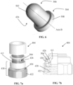
- FIG. 6 shows an exemplary configuration of a pawl 426 of the connection mechanism for the female component (e.g., the nozzle holder) 404 of FIGS.
- each pawl 426 defines a pawl body 502 having a proximal portion 504 and a distal portion 506 with a longitudinal axis B extending therebetween.
- the distal portion 506 of the pawl body 502 is configured to facilitate engagement of the pawl 426 with the laser nozzle 402 located in the hollow body 406.
- the distal portion 506 of each pawl body 502 can include a substantially curved (e.g., globular) tip configured to extend through the corresponding aperture 412 in the hollow body 406 to engage with a complementarily-shaped groove 431 of the laser nozzle 402 (as shown in FIGS. 5a and 5b ).
- each pawl body 502 is configured to facilitate disengagement of the pawl 426 from the laser nozzle 402.
- the proximal portion 504 of the pawl body 502 includes at least one flange 508 that extends substantially perpendicular (i.e., normal) to the longitudinal axis B of the pawl body 502.
- the flange 508 of the pawl 426 is adapted to contact a portion of the sleeve 418 of the nozzle holder 404, where the sleeve 418 can displace the pawl 426 away from the groove 431 and the aperture 412, thereby disengaging the nozzle holder 404 from the laser nozzle 402. Details regarding these disengagement features are described below.
- the sleeve 418 of the nozzle holder 404 is coupled to the hollow body 406 and substantially surrounds at least a portion of the outer wall 416 of the hollow body 406.
- the sleeve 418 includes a distal portion 420, a proximal portion 422 and a spring 430 disposed between the distal and proximal portions 420, 422.
- the proximal portion 422 of the sleeve 418 is configured to couple the sleeve 418 to the hollow body 406, such as via press fit.
- the proximal portion 422 of the sleeve 418 can include one or more thread engagement sections 432 disposed on an interior surface to matingly engage a cutting head (not shown).
- the sleeve 418 also substantially surrounds the pawls 426 such that at least a portion of each pawl 426 (e.g., the proximal portion 504) is disposed between the distal portion 420 and the proximal portion 422 of the sleeve 418.
- FIGS. 7a and b show an exploded view and a partial cross-sectional view, respectively of a pawl 426 in relation to various elements of the sleeve 418 of the female component (e.g., the nozzle holder) 404 of FIGS. 5a and 5b , according to some embodiments of the present invention.
- the distal end of the spring 430 of the sleeve 418 can be in physical communication with the proximal portion 504 of each pawl 426, either directly contacting the proximal portion 504 or via an intermediate translator 436 sandwiched between the spring 430 and the pawl 426.
- the intermediate translator 436 is configured as a ramp that drives/guides the corresponding pawl 426 into the respective aperture 412 during engagement or away from the aperture 412 during disengagement.
- the proximal end of the spring 430 can be in physical communication with (e.g., directly contacting) the proximal portion 422 of the sleeve 418, which is affixed to the hollow body 406 as described above.
- the proximal end of the spring 430 is affixed to the proximal portion 422 of the sleeve 418.
- the spring 430 is configured to exert a biasing force in the distal direction on the proximal portion 504 of each pawl 426, either via direct contact or via the intermediate translator 436, to axially and radially (e.g., diagonally) displace the pawl 426 relative to longitudinal axis A, such that the pawl 426 extends through its corresponding aperture 412 in the hollow body 406.
- each pawl 426 is urged to nest within its corresponding aperture 412.
- longitudinal axis B of each pawl body 502 is oriented at a non-normal angle relative to longitudinal A axis of the hollow body 402 while each pawl 426 resides in its corresponding aperture 412.
- FIGS. 8a and 8b show a sectional view and a side view, respectively, of the female component (e.g., the nozzle holder) 402 and the male component (e.g., the laser nozzle) 404 of FIGS. 5a and 5b after engagement, according to some embodiments of the present invention.
- the pawls 426 nest in their respective apertures 412 with their globular tips at the distal end 506 inter-fit with groove 431 of the laser nozzle 402.
- the pawls 426 are adapted to create an effective inner diameter of the hollow body 406 that is smaller than an outer diameter of the laser nozzle 402. Because the pawls 426 are translatable within their respective apertures 412 in both radial and axial directions, they can create a dynamic/adjustable inner diameter that precisely fit the groove 431 of the nozzle 402 (e.g., dynamically adjustable to achieve a tolerance fit). Further, in the engaged position, direct and precise contact between the nozzle holder 404 and nozzle 402 is achieved via the pawls 426.
- the distal portion 420 of the sleeve 418 is adapted to define a pawl retractor 428 that maintains physical contact with the proximal portion 504, such as the flange 508, of each pawl 426.
- the pawl retractor 428 is translatable/slidable along longitudinal axis A.
- the pawl retractor 428 is configured to engage the flanges 508 of the respective pawls 426 and, upon receiving an external force in the proximal direction, to overcome the biasing force of the spring 430 and physically displace/retract the pawls 426 from their apertures 412 for disengagement from the laser nozzle 402.
- the force exerted by the pawl retractor 428 on the flange 508 causes displacement of the pawl 426 both axially and radially (e.g., diagonally) relative to longitudinal axis A.
- the external force applied to the pawl retractor 428 for the purpose of disengagement is from a human operator or a changing machine.
- the nozzle holder 404 includes a sealing surface disposed on the inner wall 414 of the hollow body 406.
- the sealing surface configured to receive an O-ring 440 that sealingly engages a corresponding surface of the laser nozzle 402 retained to the nozzle holder 402 by the pawls 426 in the engaged position.
- the hollow body 406, the plurality of pawls 426 and the sleeve 418 are made from at least one electrically conductive material, such as the same conductive material or different conductive materials.
- the nozzle holder 404 can form a conductive current path therethrough for conducting a current to and from the laser nozzle 402 upon engagement.
- the usage of the pawls 426 in the female component (e.g., the nozzle holder) 404 for engagement with the male component (e.g., the laser nozzle 402) provides a closer and more precise location of contact between the two components 402, 404 (e.g., at the tip/distal portions 504 of the pawls).
- the force used to engage the two components 402, 404 is more directly applied for enhanced security.
- locating the retraction mechanism at the proximal portions 506 of the pawls 426 e.g., at the flange 508) allows the pawls 426 to reside closer to the entry/exit port adjacent to the distal opening 410 of the nozzle holder 404.
- the pawls 426 reside in the retraction mechanism itself (e.g., in physical contact with the pawl retractor 428), the pawls 426 are pulled away by the pawl retractor 428 during disengagement whereas additional pushing force needs to be applied to the male component to achieve disengagement or the components need to be oriented in a certain way to encourage disengagement by gravity.
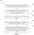
- FIG. 9 shows an exemplary process 900 for operating the connection mechanisms of the female and male components of FIGS. 5a and 5b , according to some embodiments of the present invention.
- the male component e.g., the laser nozzle
- the laser nozzle 402 includes a connection feature, such as the groove 431 that is circumferentially disposed around an outer surface of the nozzle 402.
- the female component e.g., the nozzle holder 404
- the nozzle 402 is first disposed into the substantially cylindrical hollow body 406 of the nozzle holder 404 via the distal opening 410 of the hollow body 406 (step 906).
- the spring 430 in the sleeve 418 of the nozzle holder 404 that substantially surrounds at least a portion of the outer wall 416 of the hollow body 406 is configured to bias one or more pawls 426 of the sleeve 418 for engagement with the nozzle 402 in the hollow body 406 (step 908).
- the spring 430 is adapted to exert a biasing force in the distal direction on the proximal portion 504 of each pawl 426, via either direct contact with the proximal portion 504 or an intermediate translator 436 of the sleeve 418.
- the force exerted by the spring 430 is adapted to displace the pawls 426 both radially and longitudinally with respect to longitudinal axis A of the hollow body 406, such that the pawls 426 extend through their corresponding apertures 412 on the hollow body 406 (step 910). Extension of the pawls 426 through the apertures 412 allow the distal portion 506 of each pawl 426 to inter-fit into the groove 431 of the laser nozzle 402 within the hollow body 406, thereby realizing a secure engagement between the laser nozzle 402 and the nozzle holder 404.
- an external force (in the proximal direction along longitudinal axis A) is applied to the translatable pawl retractor 428 at the distal portion 420 of the sleeve 418.
- the pawl retractor 428 is configured to maintain physical contact with the proximal portion 504 of each of the pawls 426, such as with the flange 508 on each pawl 426.
- the external force applied to the pawl retractor 428 displaces the pawl retractor 428 in the proximal direction, which in turn displaces (e.g., drives) the pawls 426 both longitudinally and radially (with respect to longitudinal axis A) to retract from their respective apertures 412, thereby disengaging the pawls 426 from the groove 431 of the nozzle 402.
- the female component 404 actuates disengagement with the male component 402.
- the nozzle 402 can be removed from the hollow body 406 of the nozzle holder 404 without any impediment.
Landscapes
- Engineering & Computer Science (AREA)
- Physics & Mathematics (AREA)
- Optics & Photonics (AREA)
- Mechanical Engineering (AREA)
- Plasma & Fusion (AREA)
- General Engineering & Computer Science (AREA)
- Spectroscopy & Molecular Physics (AREA)
- Laser Beam Processing (AREA)
Claims (13)
- Porte-buse (404) pour une tête de traitement laser d'un système de traitement laser, le porte-buse comprenant :un corps creux (406) façonné pour entrer en prise par accouplement avec une buse laser, le corps creux définissant un axe longitudinal s'étendant à travers celui-ci,le porte-buse (404) étant caractérisé par ce qui suit :le corps creux (406) définissant en outre une pluralité d'ouvertures (412) se dispersant autour d'une circonférence du corps creux, chaque ouverture s'étendant depuis une paroi intérieure jusqu'à une paroi extérieure du corps creux ;une pluralité de cliquets (426) configurés pour entrer fonctionnellement en prise avec la buse laser à l'intérieur du corps creux, dans lequel chaque cliquet a (i) une partie distale (506) configurée pour s'étendre à travers une correspondante de la pluralité d'ouvertures du corps creux pour entrer fonctionnellement en prise avec la buse laser et (ii) une partie proximale (504) configurée pour faciliter la séparation du cliquet de la buse laser ; etun manchon (418) couplé au corps creux tout en entourant sensiblement au moins une partie du corps creux et la pluralité de cliquets, le manchon incluant un rétracteur de cliquet qui est mobile le long de l'axe longitudinal avec le manchon pour appliquer une force externe sur les parties proximales de la pluralité de cliquets pour déplacer physiquement la pluralité de cliquets axialement et radialement relativement à l'axe longitudinal en éloignement du corps creux pour la séparation de la pluralité de cliquets de la buse laser, dans lequel le rétracteur de cliquet maintient un contact physique avec une partie proximale (504) de chacun de la pluralité de cliquets.
- Porte-buse de la revendication 1, dans lequel chacun de la pluralité de cliquets définit un corps de cliquet ayant la partie proximale et la partie distale avec un second axe longitudinal s'étendant entre celles-ci, dans lequel la partie distale est configurée pour faciliter l'entrée en prise du cliquet avec la buse laser et dans lequel la partie proximale est configurée pour faciliter la séparation du cliquet de la buse laser.
- Porte-buse de la revendication 2, dans lequel le second axe longitudinal est orienté à un angle non normal relativement à l'axe longitudinal du corps creux lorsqu'au moins une partie du corps de cliquet est située à l'intérieur de l'ouverture correspondante.
- Porte-buse de la revendication 2, dans lequel la partie distale de chaque cliquet inclut un bout sensiblement globulaire configuré pour s'étendre à travers l'ouverture correspondante pour entrer en prise avec une rainure façonnée de façon complémentaire de la buse laser.
- Porte-buse de la revendication 2, dans lequel la partie proximale de chaque cliquet inclut au moins une bride configurée pour maintenir un contact physique avec le rétracteur de cliquet du manchon,dans lequel facultativement a) la bride s'étend dans une direction normal relativement au second axe longitudinal du corps de cliquet ; et/oub) le rétracteur de cliquet est configuré pour entrer en prise avec les brides de cliquets respectifs de la pluralité de cliquets pour déplacer physiquement les cliquets et rétracter les cliquets depuis la pluralité d'ouvertures pour la séparation de la buse laser.
- Porte-buse de la revendication 1, dans lequel la pluralité de cliquets comprennent trois cliquets situés de façon espacée d'environ 120 degrés circonférentiellement autour du corps creux.
- Porte-buse de la revendication 1, dans lequel le manchon inclut une partie proximale et une partie distale, la partie proximale étant configurée pour se relier au corps creux, et la partie distale inclut le rétracteur de cliquet.
- Porte-buse de la revendication 7, dans lequel le manchon inclut en outre une section d'entrée en prise à filet disposée sur une surface intérieure du manchon au niveau de la partie proximale, la section d'entrée en prise à filet étant configurée pour entrer en prise par accouplement avec une tête de coupe du système de traitement laser.
- Porte-buse de la revendication 7, dans lequel le manchon inclut en outre un ressort disposé entre la partie proximale et la partie distale,dans lequel facultativement a) le ressort est configuré pour exercer une force de sollicitation pour déplacer axialement et radialement la pluralité de cliquets relativement à l'axe longitudinal de manière telle que la pluralité de cliquets s'étendent à travers les ouvertures respectives de la pluralité d'ouvertures pour entrer en prise avec la buse laser,dans lequel, plus facultativement, lorsque le ressort est étendu, la pluralité de cliquets sont adaptés pour créer un diamètre intérieur efficace du corps creux qui est plus petit qu'un diamètre extérieur de la buse laser ; et/oub) le rétracteur de cliquet maintient un contact physique avec une extrémité proximale de chacun de la pluralité de cliquets, le rétracteur de cliquet pouvant coulisser le long de l'axe longitudinal et étant configuré pour surpasser la force de sollicitation du ressort pour déplacer radialement et axialement les cliquets en éloignement d'ouvertures respectives des ouvertures pour la séparation de la buse laser.
- Porte-buse de la revendication 1, dans lequel a) le corps creux, la pluralité de cliquets, et le manchon sont faits d'au moins un matériau électroconducteur,dans lequel facultativement le porte-buse forme un chemin de courant conducteur à travers celui-ci ; et/oub) la buse comprenant en outre une surface d'étanchéité disposée sur la paroi intérieure du corps creux, la surface d'étanchéité étant configurée pour recevoir un joint torique qui entre en prise étanche avec une surface correspondante de la buse laser qui est retenue sur le porte-buse par la pluralité de cliquets.
- Porte-buse de la revendication 1, dans lequel le manchon comprend en outre :une partie distale comprenant le rétracteur de cliquet en contact physique avec une bride de chacun de la pluralité de cliquets ;une partie proximale configurée pour se relier au corps creux ;un ressort disposé entre la partie proximale du manchon et la partie distale du manchon, le ressort étant configuré pour exercer une force de sollicitation sur la pluralité de cliquets pour déplacer longitudinalement et radialement la pluralité de cliquets, de manière telle que les cliquets s'étendent à travers des ouvertures respectives de la pluralité d'ouvertures pour entrer en prise avec la buse laser,dans lequel le rétracteur de cliquet est adapté pour surpasser la force de sollicitation du ressort pour déplacer longitudinalement et radialement la pluralité de cliquets en éloignement d'ouvertures respectives des ouvertures pour la séparation de la buse laser.
- Procédé pour mettre en prise et séparer une buse laser (402) relativement à un porte-buse (404) d'une tête de traitement laser dans un système de traitement laser, le procédé comprenant :la fourniture de la buse laser (402) ayant une rainure (431) circonférentiellement disposée autour d'une surface extérieure de la buse laser ;le procédé étant caractérisé par les étapes suivantes :la fourniture du porte-buse ayant (i) un corps creux façonné pour entrer en prise par accouplement avec la buse laser, le corps creux définissant un axe longitudinal s'étendant à travers celui-ci, (ii) une pluralité d'ouvertures se dispersant autour d'une circonférence du corps creux, chaque ouverture s'étendant depuis une paroi intérieure jusqu'à une paroi extérieure du corps creux, (iii) une pluralité de cliquets, dans lequel chaque cliquet a une partie distale (506) configurée pour s'étendre à travers une correspondante de la pluralité d'ouvertures du corps creux pour entrer fonctionnellement en prise avec la buse laser et une partie proximale (504) configurée pour faciliter la séparation du cliquet de la buse laser ; et (iv) un manchon disposé autour du corps creux et de la pluralité de cliquets, le manchon (418) incluant un rétracteur de cliquet (428) qui est mobile le long de l'axe longitudinal pour déplacer physiquement la pluralité de cliquets axialement et radialement relativement à l'axe longitudinal pour la séparation de la pluralité de cliquets de la buse laser ;la disposition de la buse laser dans le corps creux du porte-buse ;la sollicitation, par un ressort situé dans le manchon, dans une direction distale, d'une extrémité proximale de chacun de la pluralité de cliquets ;le déplacement, radialement et longitudinalement, par le rétracteur de cliquet par rapport à l'axe longitudinal, de la pluralité de cliquets sur la base de la sollicitation par le ressort, de manière telle que les cliquets s'étendent à travers la pluralité d'ouvertures pour entrer en prise avec la rainure de la buse laser.
- Procédé de la revendication 12, comprenant en outre :l'application d'une force dans une direction proximale sur le rétracteur de cliquet qui est en contact physique avec une bride distale de chacun de la pluralité de cliquets ; etle déplacement, radialement et longitudinalement, par le rétracteur de cliquet, de la pluralité de cliquets en éloignement d'ouvertures respectives de la pluralité d'ouvertures par le biais du contact physique du rétracteur de cliquetavec la bride distale de chacun de la pluralité de cliquets, ainsi séparant la buse laser du porte-buse.
Applications Claiming Priority (2)
| Application Number | Priority Date | Filing Date | Title |
|---|---|---|---|
| US201962866249P | 2019-06-25 | 2019-06-25 | |
| PCT/US2020/039565 WO2020264122A1 (fr) | 2019-06-25 | 2020-06-25 | Mécanismes de verrouillage dans un système de traitement de matériau |
Publications (3)
| Publication Number | Publication Date |
|---|---|
| EP3990212A1 EP3990212A1 (fr) | 2022-05-04 |
| EP3990212C0 EP3990212C0 (fr) | 2025-06-04 |
| EP3990212B1 true EP3990212B1 (fr) | 2025-06-04 |
Family
ID=71670415
Family Applications (1)
| Application Number | Title | Priority Date | Filing Date |
|---|---|---|---|
| EP20742997.8A Active EP3990212B1 (fr) | 2019-06-25 | 2020-06-25 | Porte-buse pour tête de traitement laser d'un système de traitement laser ; procédé d'engagement et de désengagement d'une buse laser par rapport à un porte-buse d'une tête de traitement laser d'un système de traitement laser |
Country Status (4)
| Country | Link |
|---|---|
| US (1) | US11975407B2 (fr) |
| EP (1) | EP3990212B1 (fr) |
| CN (1) | CN114258334B (fr) |
| WO (1) | WO2020264122A1 (fr) |
Families Citing this family (2)
| Publication number | Priority date | Publication date | Assignee | Title |
|---|---|---|---|---|
| CN115446486B (zh) * | 2022-10-26 | 2023-04-21 | 楚能新能源股份有限公司 | 一种激光焊铜嘴 |
| JP1740862S (ja) * | 2022-12-15 | 2023-04-04 | レーザー加工用ノズル |
Family Cites Families (10)
| Publication number | Priority date | Publication date | Assignee | Title |
|---|---|---|---|---|
| US4625918A (en) * | 1983-07-29 | 1986-12-02 | Diesel Kiki Co., Ltd. | Fuel injection valve |
| JP2989318B2 (ja) * | 1991-06-12 | 1999-12-13 | 株式会社アマダ | レーザ加工ヘッド |
| JPH11221691A (ja) | 1998-02-04 | 1999-08-17 | Matsushita Electric Ind Co Ltd | レーザ加工装置 |
| DE50312360D1 (de) * | 2003-08-09 | 2010-03-11 | Trumpf Werkzeugmaschinen Gmbh | Laserbearbeitungsdüsenkupplung |
| JP2005334921A (ja) | 2004-05-26 | 2005-12-08 | Yamazaki Mazak Corp | レーザ加工機におけるノズルチェンジマガジン |
| JP4723456B2 (ja) | 2006-10-27 | 2011-07-13 | 三菱電機株式会社 | 加工ヘッドおよびノズル交換装置およびレーザ加工装置 |
| US7673911B2 (en) * | 2008-03-06 | 2010-03-09 | Liu Hsiu-Hsiung | Safety type quick connector |
| DE502008000686D1 (de) | 2008-04-09 | 2010-07-01 | Bystronic Laser Ag | Vorrichtung und Verfahren zum automatischen Wechseln von Schneiddüsen |
| CN110326367B (zh) * | 2017-02-27 | 2023-08-08 | 海别得公司 | 用于焊炬系统的螺纹连接 |
| DE102018118076A1 (de) | 2018-07-26 | 2020-01-30 | Bystronic Laser Ag | Laserdüse, Düsenaufnahme, Düsenkupplung und Werkzeugmaschine |
-
2020
- 2020-06-25 EP EP20742997.8A patent/EP3990212B1/fr active Active
- 2020-06-25 US US16/911,917 patent/US11975407B2/en active Active
- 2020-06-25 CN CN202080059861.0A patent/CN114258334B/zh active Active
- 2020-06-25 WO PCT/US2020/039565 patent/WO2020264122A1/fr not_active Ceased
Also Published As
| Publication number | Publication date |
|---|---|
| CN114258334B (zh) | 2024-07-19 |
| CN114258334A (zh) | 2022-03-29 |
| EP3990212C0 (fr) | 2025-06-04 |
| US11975407B2 (en) | 2024-05-07 |
| WO2020264122A1 (fr) | 2020-12-30 |
| EP3990212A1 (fr) | 2022-05-04 |
| US20200406396A1 (en) | 2020-12-31 |
Similar Documents
| Publication | Publication Date | Title |
|---|---|---|
| EP3443819B1 (fr) | Système de découpage à l'arc, comprenant un tube de fluide de refroidissement et autres consommables, et procédés de fonctionnement associés | |
| EP3022994B1 (fr) | Appareil et procédé permettant de fixer une électrode pour torche à plasma | |
| EP1478485B1 (fr) | Torche a plasma d'arc fonctionnant en double mode | |
| EP3990212B1 (fr) | Porte-buse pour tête de traitement laser d'un système de traitement laser ; procédé d'engagement et de désengagement d'une buse laser par rapport à un porte-buse d'une tête de traitement laser d'un système de traitement laser | |
| KR100940385B1 (ko) | 플라즈마 아크 토치용 냉각제 튜브, 냉각제 튜브를 포함하는 플라즈마 아크 토치 및 냉각제 튜브의 정렬을 위한 방법 | |
| EP2022299B1 (fr) | Torche de découpe à plasma d'arc refroidie au gaz | |
| US10098217B2 (en) | Composite consumables for a plasma arc torch | |
| JPH06198450A (ja) | プラズマ切断トーチ | |
| US20070210035A1 (en) | Electrode for a contact start plasma arc torch and contact start plasma arc torch employing such electrodes | |
| US20070145022A1 (en) | Dual mode plasma arc torch | |
| US9662747B2 (en) | Composite consumables for a plasma arc torch | |
| US9370088B2 (en) | Method and apparatus for recycling shield gas in a plasma arc torch | |
| US20170181261A1 (en) | Internally energized electrode of a plasma arc torch | |
| US20210146468A1 (en) | Systems and Methods for Separating Consumables Under Pressure in a Plasma Arc Torch | |
| US6888093B2 (en) | Apparatus for proper alignment of components in a plasma arc torch | |
| US10543559B2 (en) | Electric arc cutting or welding torch with rapid assembly system | |
| JPH10225773A (ja) | カセット式プラズマトーチ | |
| WO2017112769A1 (fr) | Électrode, alimentée en interne, d'un chalumeau à arc de plasma | |
| JP2002079378A (ja) | ティグ溶接用トーチ |
Legal Events
| Date | Code | Title | Description |
|---|---|---|---|
| STAA | Information on the status of an ep patent application or granted ep patent |
Free format text: STATUS: UNKNOWN |
|
| STAA | Information on the status of an ep patent application or granted ep patent |
Free format text: STATUS: THE INTERNATIONAL PUBLICATION HAS BEEN MADE |
|
| PUAI | Public reference made under article 153(3) epc to a published international application that has entered the european phase |
Free format text: ORIGINAL CODE: 0009012 |
|
| STAA | Information on the status of an ep patent application or granted ep patent |
Free format text: STATUS: REQUEST FOR EXAMINATION WAS MADE |
|
| 17P | Request for examination filed |
Effective date: 20220114 |
|
| AK | Designated contracting states |
Kind code of ref document: A1 Designated state(s): AL AT BE BG CH CY CZ DE DK EE ES FI FR GB GR HR HU IE IS IT LI LT LU LV MC MK MT NL NO PL PT RO RS SE SI SK SM TR |
|
| DAV | Request for validation of the european patent (deleted) | ||
| DAX | Request for extension of the european patent (deleted) | ||
| RIN1 | Information on inventor provided before grant (corrected) |
Inventor name: KNAPP, DAVID, K. Inventor name: HARP, CARMEN Inventor name: BOUTHILLIER, DAVID, L. |
|
| STAA | Information on the status of an ep patent application or granted ep patent |
Free format text: STATUS: EXAMINATION IS IN PROGRESS |
|
| 17Q | First examination report despatched |
Effective date: 20240216 |
|
| GRAP | Despatch of communication of intention to grant a patent |
Free format text: ORIGINAL CODE: EPIDOSNIGR1 |
|
| STAA | Information on the status of an ep patent application or granted ep patent |
Free format text: STATUS: GRANT OF PATENT IS INTENDED |
|
| INTG | Intention to grant announced |
Effective date: 20241010 |
|
| GRAJ | Information related to disapproval of communication of intention to grant by the applicant or resumption of examination proceedings by the epo deleted |
Free format text: ORIGINAL CODE: EPIDOSDIGR1 |
|
| STAA | Information on the status of an ep patent application or granted ep patent |
Free format text: STATUS: EXAMINATION IS IN PROGRESS |
|
| GRAP | Despatch of communication of intention to grant a patent |
Free format text: ORIGINAL CODE: EPIDOSNIGR1 |
|
| STAA | Information on the status of an ep patent application or granted ep patent |
Free format text: STATUS: GRANT OF PATENT IS INTENDED |
|
| INTC | Intention to grant announced (deleted) | ||
| INTG | Intention to grant announced |
Effective date: 20250219 |
|
| GRAS | Grant fee paid |
Free format text: ORIGINAL CODE: EPIDOSNIGR3 |
|
| GRAA | (expected) grant |
Free format text: ORIGINAL CODE: 0009210 |
|
| STAA | Information on the status of an ep patent application or granted ep patent |
Free format text: STATUS: THE PATENT HAS BEEN GRANTED |
|
| AK | Designated contracting states |
Kind code of ref document: B1 Designated state(s): AL AT BE BG CH CY CZ DE DK EE ES FI FR GB GR HR HU IE IS IT LI LT LU LV MC MK MT NL NO PL PT RO RS SE SI SK SM TR |
|
| REG | Reference to a national code |
Ref country code: GB Ref legal event code: FG4D |
|
| REG | Reference to a national code |
Ref country code: CH Ref legal event code: EP |
|
| REG | Reference to a national code |
Ref country code: IE Ref legal event code: FG4D |
|
| U01 | Request for unitary effect filed |
Effective date: 20250605 |
|
| U07 | Unitary effect registered |
Designated state(s): AT BE BG DE DK EE FI FR IT LT LU LV MT NL PT RO SE SI Effective date: 20250613 |
|
| U20 | Renewal fee for the european patent with unitary effect paid |
Year of fee payment: 6 Effective date: 20250827 |
|
| PG25 | Lapsed in a contracting state [announced via postgrant information from national office to epo] |
Ref country code: ES Free format text: LAPSE BECAUSE OF FAILURE TO SUBMIT A TRANSLATION OF THE DESCRIPTION OR TO PAY THE FEE WITHIN THE PRESCRIBED TIME-LIMIT Effective date: 20250604 |
|
| PG25 | Lapsed in a contracting state [announced via postgrant information from national office to epo] |
Ref country code: NO Free format text: LAPSE BECAUSE OF FAILURE TO SUBMIT A TRANSLATION OF THE DESCRIPTION OR TO PAY THE FEE WITHIN THE PRESCRIBED TIME-LIMIT Effective date: 20250904 Ref country code: GR Free format text: LAPSE BECAUSE OF FAILURE TO SUBMIT A TRANSLATION OF THE DESCRIPTION OR TO PAY THE FEE WITHIN THE PRESCRIBED TIME-LIMIT Effective date: 20250905 |
|
| PG25 | Lapsed in a contracting state [announced via postgrant information from national office to epo] |
Ref country code: PL Free format text: LAPSE BECAUSE OF FAILURE TO SUBMIT A TRANSLATION OF THE DESCRIPTION OR TO PAY THE FEE WITHIN THE PRESCRIBED TIME-LIMIT Effective date: 20250604 |
|
| PG25 | Lapsed in a contracting state [announced via postgrant information from national office to epo] |
Ref country code: HR Free format text: LAPSE BECAUSE OF FAILURE TO SUBMIT A TRANSLATION OF THE DESCRIPTION OR TO PAY THE FEE WITHIN THE PRESCRIBED TIME-LIMIT Effective date: 20250604 |
|
| PG25 | Lapsed in a contracting state [announced via postgrant information from national office to epo] |
Ref country code: RS Free format text: LAPSE BECAUSE OF FAILURE TO SUBMIT A TRANSLATION OF THE DESCRIPTION OR TO PAY THE FEE WITHIN THE PRESCRIBED TIME-LIMIT Effective date: 20250904 |
|
| PGFP | Annual fee paid to national office [announced via postgrant information from national office to epo] |
Ref country code: CZ Payment date: 20250724 Year of fee payment: 6 |
|
| PG25 | Lapsed in a contracting state [announced via postgrant information from national office to epo] |
Ref country code: IS Free format text: LAPSE BECAUSE OF FAILURE TO SUBMIT A TRANSLATION OF THE DESCRIPTION OR TO PAY THE FEE WITHIN THE PRESCRIBED TIME-LIMIT Effective date: 20251004 |
|
| PG25 | Lapsed in a contracting state [announced via postgrant information from national office to epo] |
Ref country code: SM Free format text: LAPSE BECAUSE OF FAILURE TO SUBMIT A TRANSLATION OF THE DESCRIPTION OR TO PAY THE FEE WITHIN THE PRESCRIBED TIME-LIMIT Effective date: 20250604 |
|
| PG25 | Lapsed in a contracting state [announced via postgrant information from national office to epo] |
Ref country code: SK Free format text: LAPSE BECAUSE OF FAILURE TO SUBMIT A TRANSLATION OF THE DESCRIPTION OR TO PAY THE FEE WITHIN THE PRESCRIBED TIME-LIMIT Effective date: 20250604 |
|
| REG | Reference to a national code |
Ref country code: CH Ref legal event code: H13 Free format text: ST27 STATUS EVENT CODE: U-0-0-H10-H13 (AS PROVIDED BY THE NATIONAL OFFICE) Effective date: 20260127 |
|
| PG25 | Lapsed in a contracting state [announced via postgrant information from national office to epo] |
Ref country code: MC Free format text: LAPSE BECAUSE OF FAILURE TO SUBMIT A TRANSLATION OF THE DESCRIPTION OR TO PAY THE FEE WITHIN THE PRESCRIBED TIME-LIMIT Effective date: 20250604 |
|
| PLBE | No opposition filed within time limit |
Free format text: ORIGINAL CODE: 0009261 |
|
| STAA | Information on the status of an ep patent application or granted ep patent |
Free format text: STATUS: NO OPPOSITION FILED WITHIN TIME LIMIT |
|
| PG25 | Lapsed in a contracting state [announced via postgrant information from national office to epo] |
Ref country code: IE Free format text: LAPSE BECAUSE OF NON-PAYMENT OF DUE FEES Effective date: 20250625 |
|
| REG | Reference to a national code |
Ref country code: CH Ref legal event code: L10 Free format text: ST27 STATUS EVENT CODE: U-0-0-L10-L00 (AS PROVIDED BY THE NATIONAL OFFICE) Effective date: 20260416 |
|
| PG25 | Lapsed in a contracting state [announced via postgrant information from national office to epo] |
Ref country code: CH Free format text: LAPSE BECAUSE OF NON-PAYMENT OF DUE FEES Effective date: 20250630 |