EP3990258B1 - Systèmes et procédé de fabrication additive de dispositifs dentaires à l'aide de résines photopolymères - Google Patents
Systèmes et procédé de fabrication additive de dispositifs dentaires à l'aide de résines photopolymères Download PDFInfo
- Publication number
- EP3990258B1 EP3990258B1 EP20757121.7A EP20757121A EP3990258B1 EP 3990258 B1 EP3990258 B1 EP 3990258B1 EP 20757121 A EP20757121 A EP 20757121A EP 3990258 B1 EP3990258 B1 EP 3990258B1
- Authority
- EP
- European Patent Office
- Prior art keywords
- layer
- layers
- amount
- areas
- pattern
- Prior art date
- Legal status (The legal status is an assumption and is not a legal conclusion. Google has not performed a legal analysis and makes no representation as to the accuracy of the status listed.)
- Active
Links
Images






Classifications
-
- A—HUMAN NECESSITIES
- A61—MEDICAL OR VETERINARY SCIENCE; HYGIENE
- A61C—DENTISTRY; APPARATUS OR METHODS FOR ORAL OR DENTAL HYGIENE
- A61C13/00—Dental prostheses; Making same
- A61C13/0003—Making bridge-work, inlays, implants or the like
- A61C13/0006—Production methods
- A61C13/0019—Production methods using three dimensional printing
-
- A—HUMAN NECESSITIES
- A61—MEDICAL OR VETERINARY SCIENCE; HYGIENE
- A61C—DENTISTRY; APPARATUS OR METHODS FOR ORAL OR DENTAL HYGIENE
- A61C7/00—Orthodontics, i.e. obtaining or maintaining the desired position of teeth, e.g. by straightening, evening, regulating, separating, or by correcting malocclusions
- A61C7/08—Mouthpiece-type retainers or positioners, e.g. for both the lower and upper arch
-
- A—HUMAN NECESSITIES
- A61—MEDICAL OR VETERINARY SCIENCE; HYGIENE
- A61C—DENTISTRY; APPARATUS OR METHODS FOR ORAL OR DENTAL HYGIENE
- A61C7/00—Orthodontics, i.e. obtaining or maintaining the desired position of teeth, e.g. by straightening, evening, regulating, separating, or by correcting malocclusions
- A61C7/12—Brackets; Arch wires; Combinations thereof; Accessories therefor
- A61C7/14—Brackets; Fixing brackets to teeth
- A61C7/146—Positioning or placement of brackets; Tools therefor
-
- B—PERFORMING OPERATIONS; TRANSPORTING
- B29—WORKING OF PLASTICS; WORKING OF SUBSTANCES IN A PLASTIC STATE IN GENERAL
- B29C—SHAPING OR JOINING OF PLASTICS; SHAPING OF MATERIAL IN A PLASTIC STATE, NOT OTHERWISE PROVIDED FOR; AFTER-TREATMENT OF THE SHAPED PRODUCTS, e.g. REPAIRING
- B29C64/00—Additive manufacturing, i.e. manufacturing of three-dimensional [3D] objects by additive deposition, additive agglomeration or additive layering, e.g. by 3D printing, stereolithography or selective laser sintering
- B29C64/10—Processes of additive manufacturing
- B29C64/106—Processes of additive manufacturing using only liquids or viscous materials, e.g. depositing a continuous bead of viscous material
- B29C64/124—Processes of additive manufacturing using only liquids or viscous materials, e.g. depositing a continuous bead of viscous material using layers of liquid which are selectively solidified
-
- B—PERFORMING OPERATIONS; TRANSPORTING
- B29—WORKING OF PLASTICS; WORKING OF SUBSTANCES IN A PLASTIC STATE IN GENERAL
- B29C—SHAPING OR JOINING OF PLASTICS; SHAPING OF MATERIAL IN A PLASTIC STATE, NOT OTHERWISE PROVIDED FOR; AFTER-TREATMENT OF THE SHAPED PRODUCTS, e.g. REPAIRING
- B29C64/00—Additive manufacturing, i.e. manufacturing of three-dimensional [3D] objects by additive deposition, additive agglomeration or additive layering, e.g. by 3D printing, stereolithography or selective laser sintering
- B29C64/10—Processes of additive manufacturing
- B29C64/106—Processes of additive manufacturing using only liquids or viscous materials, e.g. depositing a continuous bead of viscous material
- B29C64/124—Processes of additive manufacturing using only liquids or viscous materials, e.g. depositing a continuous bead of viscous material using layers of liquid which are selectively solidified
- B29C64/129—Processes of additive manufacturing using only liquids or viscous materials, e.g. depositing a continuous bead of viscous material using layers of liquid which are selectively solidified characterised by the energy source therefor, e.g. by global irradiation combined with a mask
-
- B—PERFORMING OPERATIONS; TRANSPORTING
- B29—WORKING OF PLASTICS; WORKING OF SUBSTANCES IN A PLASTIC STATE IN GENERAL
- B29C—SHAPING OR JOINING OF PLASTICS; SHAPING OF MATERIAL IN A PLASTIC STATE, NOT OTHERWISE PROVIDED FOR; AFTER-TREATMENT OF THE SHAPED PRODUCTS, e.g. REPAIRING
- B29C64/00—Additive manufacturing, i.e. manufacturing of three-dimensional [3D] objects by additive deposition, additive agglomeration or additive layering, e.g. by 3D printing, stereolithography or selective laser sintering
- B29C64/20—Apparatus for additive manufacturing; Details thereof or accessories therefor
- B29C64/264—Arrangements for irradiation
- B29C64/286—Optical filters, e.g. masks
-
- B—PERFORMING OPERATIONS; TRANSPORTING
- B29—WORKING OF PLASTICS; WORKING OF SUBSTANCES IN A PLASTIC STATE IN GENERAL
- B29C—SHAPING OR JOINING OF PLASTICS; SHAPING OF MATERIAL IN A PLASTIC STATE, NOT OTHERWISE PROVIDED FOR; AFTER-TREATMENT OF THE SHAPED PRODUCTS, e.g. REPAIRING
- B29C64/00—Additive manufacturing, i.e. manufacturing of three-dimensional [3D] objects by additive deposition, additive agglomeration or additive layering, e.g. by 3D printing, stereolithography or selective laser sintering
- B29C64/30—Auxiliary operations or equipment
- B29C64/386—Data acquisition or data processing for additive manufacturing
- B29C64/393—Data acquisition or data processing for additive manufacturing for controlling or regulating additive manufacturing processes
-
- B—PERFORMING OPERATIONS; TRANSPORTING
- B33—ADDITIVE MANUFACTURING TECHNOLOGY
- B33Y—ADDITIVE MANUFACTURING, i.e. MANUFACTURING OF THREE-DIMENSIONAL [3D] OBJECTS BY ADDITIVE DEPOSITION, ADDITIVE AGGLOMERATION OR ADDITIVE LAYERING, e.g. BY 3D PRINTING, STEREOLITHOGRAPHY OR SELECTIVE LASER SINTERING
- B33Y10/00—Processes of additive manufacturing
-
- B—PERFORMING OPERATIONS; TRANSPORTING
- B33—ADDITIVE MANUFACTURING TECHNOLOGY
- B33Y—ADDITIVE MANUFACTURING, i.e. MANUFACTURING OF THREE-DIMENSIONAL [3D] OBJECTS BY ADDITIVE DEPOSITION, ADDITIVE AGGLOMERATION OR ADDITIVE LAYERING, e.g. BY 3D PRINTING, STEREOLITHOGRAPHY OR SELECTIVE LASER SINTERING
- B33Y50/00—Data acquisition or data processing for additive manufacturing
- B33Y50/02—Data acquisition or data processing for additive manufacturing for controlling or regulating additive manufacturing processes
-
- B—PERFORMING OPERATIONS; TRANSPORTING
- B33—ADDITIVE MANUFACTURING TECHNOLOGY
- B33Y—ADDITIVE MANUFACTURING, i.e. MANUFACTURING OF THREE-DIMENSIONAL [3D] OBJECTS BY ADDITIVE DEPOSITION, ADDITIVE AGGLOMERATION OR ADDITIVE LAYERING, e.g. BY 3D PRINTING, STEREOLITHOGRAPHY OR SELECTIVE LASER SINTERING
- B33Y80/00—Products made by additive manufacturing
-
- A—HUMAN NECESSITIES
- A61—MEDICAL OR VETERINARY SCIENCE; HYGIENE
- A61C—DENTISTRY; APPARATUS OR METHODS FOR ORAL OR DENTAL HYGIENE
- A61C7/00—Orthodontics, i.e. obtaining or maintaining the desired position of teeth, e.g. by straightening, evening, regulating, separating, or by correcting malocclusions
- A61C7/002—Orthodontic computer assisted systems
Definitions
- US Patent No. 5,965,079 describes a method for stereolithographically making an object by alternating the order in which similar sets of vectors are exposed over two or more layers.
- additive manufacturing is the manufacturing of oral appliances and components.
- some aspects of additive manufacturing have made this approach less than ideally suited for at least some oral appliances.
- directly fabricated polymers may have less than ideal strength and can warp in at least some instances.
- the amount of light energy delivered to the initial layers can be substantially greater than the amount of light energy used to fabricate the rest of the part.
- the amount of light energy is related to the amount of polymer cross linking in the directly fabricated photopolymer.
- the light energy may be increased for the first layers to increase adhesion between the photopolymer and a fabricate platform. If the initial layers, also referred to as the 'burn in' layers, do not provide adequate adhesion, the part may not the fabricated successfully.
- the light energy can also be increased for the initial layers to compensate for inaccuracies in the initial levelling process, in which the application platform is less than ideally aligned with the optical beam components used to fabricate the layers. The light energy may reduce for the remaining layers, which can be directly fabricated with similar amounts of light energy.
- Changing the amount of light energy among the layers can cause warpage of the part in at least some instances. Delivering different amounts of light energy to different layers typically results in different amounts of crosslinking in the layers.
- the photopolymers can shrink when cured, and the amount of shrinkage can be related to the amount of crosslinking. Varying amounts of crosslinking and curing may produce different levels of shrinkage within a part. The differing amounts of shrinkage can lead to the development of internal stresses within the part that may manifest as warpage or curling.
- This effect can be further enhanced with directly fabricated parts in which the lateral dimensions of the part along the build platform area are large compared to the thickness of the part along the fabrication direction. Additionally, structures that are located away from the build platform may experience movement as the base structure warps. To decrease these effects, parts can be suspended away from the build platform and held there by thin pillars that join the part to the platform. However, such pillars may take additional time to fabricate and may be removed in a subsequent manufacturing step, increasing the time and complexity of the manufacturing process.
- an oral appliance comprises an elongate structure with a surface directly fabricated on a platform of a additive manufacturing machine, such as a 3D printer, in which the oral appliance comprises one or more structures to decrease deformation and decrease manufacturing steps, such as the removal of standoffs.
- the presently disclosed methods, apparatus and appliances are well suited for direct fabrication with deposition manufacturing, sometimes referred to as additive manufacturing or 3D printing, fused deposition modeling, stereo lithography (SLA), digital light projector (DLP) printing, continuous DLP, inkjet spray, and metal printing. Also, the presently disclosed methods and apparatus are well suited for the additive manufacturing of different materials onto a single appliance, such as inkjet printing with a plurality of different materials to fabricate an appliance comprising a plurality of different materials.
- the orthodontic appliances herein can be produced using direct fabrication, such as additive manufacturing techniques (also referred to herein as "3D printing").
- Additive manufacturing techniques can be categorized as follows: (1) vat photopolymerization (e.g., stereolithography), in which an object is constructed layer by layer from a vat of liquid photopolymer resin; (2) material jetting, in which material is jetted onto a build platform using either a continuous or drop on demand (DOD) approach; (3) binder jetting, in which alternating layers of a build material (e.g., a powder-based material) and a binding material (e.g., a liquid binder) are deposited by a print head; (4) fused deposition modeling (FDM), in which material is drawn though a nozzle, heated, and deposited layer by layer; (5) powder bed fusion, including but not limited to direct metal laser sintering (DMLS), electron beam melting (EBM), selective heat sintering (SHS), selective laser melting (S)
- DMLS direct metal
- stereolithography can be used to directly fabricate one or more of the appliances herein.
- stereolithography involves selective polymerization of a photosensitive resin (e.g., a photopolymer) according to a desired cross-sectional shape using light (e.g., ultraviolet light).
- the object geometry can be built up in a layer-by-layer fashion by sequentially polymerizing a plurality of object cross-sections.
- the appliances herein can be directly fabricated using selective laser sintering.
- selective laser sintering involves using a laser beam to selectively melt and fuse a layer of powdered material according to a desired cross-sectional shape in order to build up the object geometry.
- the appliances herein can be directly fabricated by fused deposition modeling.
- fused deposition modeling involves melting and selectively depositing a thin filament of thermoplastic polymer in a layer-by-layer manner in order to form an object.
- material jetting can be used to directly fabricate the appliances herein.
- material jetting involves jetting or extruding one or more materials onto a build surface in order to form successive layers of the object geometry.
- the direct fabrication methods provided herein build up the object geometry in a layer-by-layer fashion, with successive layers being formed in discrete build steps.
- direct fabrication methods that allow for continuous build-up of an object geometry can be used, referred to herein as "continuous direct fabrication.”
- continuous direct fabrication Various types of continuous direct fabrication methods can be used.
- the appliances herein are fabricated using "continuous liquid interphase printing," in which an object is continuously built up from a reservoir of photopolymerizable resin by forming a gradient of partially cured resin between the building surface of the object and a polymerization-inhibited "dead zone.”
- a semi-permeable membrane is used to control transport of a photopolymerization inhibitor (e.g., oxygen) into the dead zone in order to form the polymerization gradient.
- a photopolymerization inhibitor e.g., oxygen
- Continuous liquid interphase printing can achieve fabrication speeds about 25 times to about 100 times faster than other direct fabrication methods, and speeds about 1000 times faster can be achieved with the incorporation of cooling systems. Continuous liquid interphase printing is described in U.S. Patent Publication Nos. 2015/0097315 , 2015/0097316 , and 2015/0102532 .
- a continuous direct fabrication method can achieve continuous build-up of an object geometry by continuous movement of the build platform (e.g., along the vertical or Z-direction) during the irradiation phase, such that the hardening depth of the irradiated photopolymer is controlled by the movement speed. Accordingly, continuous polymerization of material on the build surface can be achieved.
- Such methods are described in U.S. Pat. No. 7,892,474 .
- a continuous direct fabrication method can involve extruding a composite material composed of a curable liquid material surrounding a solid strand.
- the composite material can be extruded along a continuous three-dimensional path in order to form the object.
- a continuous direct fabrication method utilizes a "heliolithography" approach in which the liquid photopolymer is cured with focused radiation while the build platform is continuously rotated and raised. Accordingly, the object geometry can be continuously built up along a spiral build path.
- a "heliolithography" approach in which the liquid photopolymer is cured with focused radiation while the build platform is continuously rotated and raised. Accordingly, the object geometry can be continuously built up along a spiral build path.
- the direct fabrication approaches provided herein are compatible with a wide variety of materials, including but not limited to one or more of the following: polymer matrix reinforced with ceramic or metallic polymers, a polyester, a co-polyester, a polycarbonate, a thermoplastic polyurethane, a polypropylene, a polyethylene, a polypropylene and polyethylene copolymer, an acrylic, a cyclic block copolymer, a polyetheretherketone, a polyamide, a polyethylene terephthalate, a polybutylene terephthalate, a polyetherimide, a polyethersulfone, a polytrimethylene terephthalate, a styrenic block copolymer (SBC), a silicone rubber, an elastomeric alloy, a thermoplastic elastomer (TPE), a thermoplastic vulcanizate (TPV) elastomer, a polyurethane elastomer, a block copolymer elasto
- the materials used for direct fabrication can be provided in an uncured form (e.g., as a liquid, resin, powder, etc.) and can be cured (e.g., by photopolymerization, light curing, gas curing, laser curing, crosslinking, etc.) in order to form an orthodontic appliance or a portion thereof.
- the properties of the material before curing may differ from the properties of the material after curing.
- the materials herein can exhibit sufficient strength, stiffness, durability, biocompatibility, etc. for use in an orthodontic appliance.
- the post-curing properties of the materials used can be selected according to the desired properties for the corresponding portions of the appliance.
- relatively rigid portions of the orthodontic appliance can be formed via direct fabrication using one or more of the following materials: a polyester, a co-polyester, a polycarbonate, a thermoplastic polyurethane, a polypropylene, a polyethylene, a polypropylene and polyethylene copolymer, an acrylic, a cyclic block copolymer, a polyetheretherketone, a polyamide, a polyethylene terephthalate, a polybutylene terephthalate, a polyetherimide, a polyethersulfone, and/or a polytrimethylene terephthalate.
- relatively elastic portions of the orthodontic appliance can be formed via direct fabrication using one or more of the following materials: a styrenic block copolymer (SBC), a silicone rubber, an elastomeric alloy, a thermoplastic elastomer (TPE), a thermoplastic vulcanizate (TPV) elastomer, a polyurethane elastomer, a block copolymer elastomer, a polyolefin blend elastomer, a thermoplastic co-polyester elastomer, and/or a thermoplastic polyamide elastomer.
- SBC styrenic block copolymer
- TPE thermoplastic elastomer
- TPV thermoplastic vulcanizate
- a multi-material direct fabrication method involves concurrently forming an object from multiple materials in a single manufacturing step using the same fabrication machine and method.
- a multi-tip extrusion apparatus can be used to selectively dispense multiple types of materials (e.g., resins, liquids, solids, or combinations thereof) from distinct material supply sources in order to fabricate an object from a plurality of different materials.
- materials e.g., resins, liquids, solids, or combinations thereof
- a multi-material direct fabrication method can involve forming an object from multiple materials in a plurality of sequential manufacturing steps.
- a first portion of the object can be formed from a first material in accordance with any of the direct fabrication methods herein, then a second portion of the object can be formed from a second material in accordance with methods herein, and so on, until the entirety of the object has been formed.
- the relative arrangement of the first and second portions can be varied as desired, e.g., the first portion can be partially or wholly encapsulated by the second portion of the object.
- the sequential manufacturing steps can be performed using the same fabrication machine or different fabrication machines, and can be performed using the same fabrication method or different fabrication methods.
- a sequential multi-manufacturing procedure can involve forming a first portion of the object using stereolithography and a second portion of the object using fused deposition modeling.
- Direct fabrication can provide various advantages compared to other manufacturing approaches. For instance, in contrast to indirect fabrication, direct fabrication permits production of an orthodontic appliance without utilizing any molds or templates for shaping the appliance, thus reducing the number of manufacturing steps involved and improving the resolution and accuracy of the final appliance geometry. Additionally, direct fabrication permits precise control over the three-dimensional geometry of the appliance, such as the appliance thickness. Complex structures and/or auxiliary components can be formed integrally as a single piece with the appliance shell in a single manufacturing step, rather than being added to the shell in a separate manufacturing step.
- direct fabrication is used to produce appliance geometries that would be difficult to create using alternative manufacturing techniques, such as appliances with very small or fine features, complex geometric shapes, undercuts, interproximal structures, shells with variable thicknesses, and/or internal structures (e.g., for improving strength with reduced weight and material usage).
- the direct fabrication approaches herein permit fabrication of an orthodontic appliance with feature sizes of less than or equal to about 5 ⁇ m, or within a range from about 5 ⁇ m to about 50 ⁇ m, or within a range from about 20 ⁇ m to about 50 ⁇ m.
- the direct fabrication techniques described herein can be used to produce appliances with substantially isotropic material properties, e.g., substantially the same or similar strengths along all directions.
- the direct fabrication approaches herein permit production of an orthodontic appliance with a strength that varies by no more than about 25%, about 20%, about 15%, about 10%, about 5%, about 1%, or about 0.5% along all directions. Additionally, the direct fabrication approaches herein can be used to produce orthodontic appliances at a faster speed compared to other manufacturing techniques.
- the direct fabrication approaches herein allow for production of an orthodontic appliance in a time interval less than or equal to about 1 hour, about 30 minutes, about 25 minutes, about 20 minutes, about 15 minutes, about 10 minutes, about 5 minutes, about 4 minutes, about 3 minutes, about 2 minutes, about 1 minutes, or about 30 seconds.
- Such manufacturing speeds allow for rapid "chair-side" production of customized appliances, e.g., during a routine appointment or checkup.
- the direct fabrication methods described herein implement process controls for various machine parameters of a direct fabrication system or device in order to ensure that the resultant appliances are fabricated with a high degree of precision. Such precision can be beneficial for ensuring accurate delivery of a desired force system to the teeth in order to effectively elicit tooth movements.
- Process controls can be implemented to account for process variability arising from multiple sources, such as the material properties, machine parameters, environmental variables, and/or post-processing parameters.
- Material properties may vary depending on the properties of raw materials, purity of raw materials, and/or process variables during mixing of the raw materials.
- resins or other materials for direct fabrication should be manufactured with tight process control to ensure little variability in photo-characteristics, material properties (e.g., viscosity, surface tension), physical properties (e.g., modulus, strength, elongation) and/or thermal properties (e.g., glass transition temperature, heat deflection temperature).
- Process control for a material manufacturing process can be achieved with screening of raw materials for physical properties and/or control of temperature, humidity, and/or other process parameters during the mixing process. By implementing process controls for the material manufacturing procedure, reduced variability of process parameters and more uniform material properties for each batch of material can be achieved. Residual variability in material properties can be compensated with process control on the machine, as discussed further herein.
- Machine parameters can include curing parameters.
- curing parameters can include power, curing time, and/or grayscale of the full image.
- curing parameters can include power, speed, beam size, beam shape and/or power distribution of the beam.
- curing parameters can include material drop size, viscosity, and/or curing power.
- gray scale can be measured and calibrated before, during, and/or at the end of each build, and/or at predetermined time intervals (e.g., every nth build, once per hour, once per day, once per week, etc.), depending on the stability of the system.
- material properties and/or photo-characteristics can be provided to the fabrication machine, and a machine process control module can use these parameters to adjust machine parameters (e.g., power, time, gray scale, etc.) to compensate for variability in material properties.
- environmental variables e.g., temperature, humidity, Sunlight or exposure to other energy/curing source
- machine parameters can be adjusted to compensate for environmental variables.
- post-processing of appliances includes cleaning, post-curing, and/or support removal processes.
- Relevant post-processing parameters can include purity of cleaning agent, cleaning pressure and/or temperature, cleaning time, post-curing energy and/or time, and/or consistency of support removal process. These parameters can be measured and adjusted as part of a process control scheme.
- appliance physical properties can be varied by modifying the post-processing parameters. Adjusting post-processing machine parameters can provide another way to compensate for variability in material properties and/or machine properties.
- oral components such as orthodontic devices and molds for orthodontic devices
- the methods and apparatus disclosed herein will find application many fields such implantable devices, cardiology, orthopedics, and generally product design within the healthcare industry. It may also be useful in other industries such as aviation, automotive, in particular for component fabrication etc.
- FIG. 1 illustrates an exemplary dental device 10 for positioning an attachment 12 on a patient's tooth 13.
- One or more the components of the device 10 can be directly fabricated to inhibit warpage as described herein, and the device 10 may comprise at least one component directly fabricated with at least one layer to inhibit warpage as described herein.
- the dental device 10 may comprise a body 16, an attachment 12 and one or more supports 14.
- the dental device 10 can be sized and shaped to be positioned on a plurality of a patient's teeth present in an upper or lower jaw.
- the body 16 may include many suitable structures for placement on one or more of the patient's teeth, such as a thin shell polymeric appliance comprising a plurality of teeth receiving cavities sized and shaped to receive the patient's teeth.
- the dental device 10 may couple to the attachment 12 by one or more supports 14, and the body 16 may comprise an opening so as to expose at least a portion of tooth 13 during placement of the attachment 12.
- the dental device 10 and the attachment 12 may be formed as a single component.
- the dental device 10 and the attachment 12 may be directly fabricated at the same time using additive manufacturing as described herein.
- some components of the dental device 10 are manufactured separately and coupled together prior to placement on the patient's teeth.
- a freestanding attachment 12 can be coupled to the supports 14 using conventional joining techniques such as plastic welding or adhesives prior to placing the dental device 10 on the patient's tooth.
- the attachment 12 coupled to the body 16 prior to placement on the patient's teeth can allow the attachment to be accurately positioned on the patient's tooth. Once the attachment 12 has been appropriately positioned on the patient's tooth, the attachment 12 can be adhered to the tooth.
- the attachment 12 can be used to apply beneficial forces to the tooth with polymeric shell dental appliances.
- the attachment can be used with the Invisalign ® treatment commercially available from Align Technology.
- the described devices and methods are applicable to the direct fabrication of the dental device 10 with the attachment 12 as a single component, direct fabrication of the dental device 10 with the attachment 12 as a separate component, or to the direct fabrication of the attachment 12.
- FIG. 2 illustrates the attachment 12 secured to a patient's tooth 13.
- the attachment 12 may be used as an anchor in orthodontic procedures and may enhance the performance of an orthodontic device in the movement of teeth.
- the attachment 12 may be bonded to the tooth by an adhesive.
- a surface of the attachment 12 may comprise a smooth surface to bond to the tooth, or have a texture to enhance the bonding between the tooth and the attachment 12.
- the surface bonded to the tooth may have an attachment surface that is complementary to a surface of the tooth to which it is being bonded.
- FIG. 3 shows an exemplary dental device 10 placed a patient's teeth.
- the device 10 may comprise at least one component fabricated with at least one layer to inhibit warpage, as described herein.
- the device 10 may comprise a surface 11, which has been directly fabricated on, for example, a stereolithographic 3-D printer.
- the surface 11 can be located on a side of the dental device opposite a tooth engaging surface of the device.
- the surface 11 may be located occlusal of the teeth.
- the surface 11 may be fabricated on a build platform, sometimes referred to a fabrication platform.
- the surface 11 may comprise one or more burn in layers, as described herein.
- the at least one layer to inhibit warpage may comprise structures located in the burn in layer or other layers of the device, e.g. stress relieving structures, or structures located on different layers away from surface 11, as described herein.
- the dental device 10 comprises a body 16, a plurality of attachments 12, a plurality of supports 14 that couple the attachments 12 to the body 16, a plurality of registration structures 18, and a plurality of support structures 20 that couple the registration structures 18 to the body 16.
- the body 16 may comprise one or more elongate structures 17.
- the body 16 may comprise a single U-shaped component comprising one or more elongate structures 17, or it may comprise a plurality of elongate structures 17 that may be joined together.
- the locations of each of the plurality of attachments on each of the teeth may be determined by a treatment professional with planning software, and the device 10 directly fabricated in accordance with the positions determined with the treatment planning software.
- the body 16 may provide a reference structure for positioning the attachments 12 relative to a patient's teeth while the registration structures 18 may secure and position the body 16 relative to the patient's teeth. While the registration structures can be placed on the patient's teeth in many ways, in some embodiments the registration structures are located on the body 16 for placement at mesial locations on the patient's teeth.
- the dental device 10 may be positioned in a patient's mouth with the registration structures 18 contacting the patient's teeth to orient the attachments 12 in a predetermined location. With the attachments 12 in the correct location, the attachment 12 may be bonded to the tooth. Once the attachments 12 are bonded to the tooth, the supports 14 may be removed from the attachments 12 freeing the dental device 10 from the patient's teeth. The dental device 10 may then be removed from the patient's mouth leaving the attachments 12 bonded to the patient's teeth in the desired locations, for example the predetermined locations.
- the elongate body 16 comprises one or more structures to decrease deformation, as described herein, to place the attachments 12 at the appropriate positions on the patient's teeth.
- the one or more elongate structures 17 of body 16 may comprise the one or more structures to decrease deformation, as described herein, to place attachments 12 at the appropriate locations on the patient's teeth.
- the surface 11 comprises a plurality of stress relieving structures, such as a plurality of platforms.
- the elongate structures 17 may comprise a layer to inhibit warpage of the surface 11, such as an opposing layer with a similar amount cross-lining and light exposure as the burn in layer of surface 11.
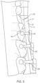
- FIGS. 4 and 5 show an exemplary dental device 10 in connection with a 3-D digital model 25 of a patient's teeth and FIG. 6 shows a portion of the dental device 10 in a free standing configuration.
- the 3-D digital model 25 can be used as a basis to generate instructions to directly fabricate one or more components of the dental device 10, and in some embodiments the entire dental device 10.
- One or more the components of the device 10 can be directly fabricated to inhibit warpage, as described herein, and the device 10 may comprise at least one component directly fabricated with at least one layer to inhibit warpage, as described herein.
- the device 10 may comprise a surface 11, which has been directly fabricated on an additive manufacturing device, such as 3-D printer. These structures to decrease warpage can be identified on the 3-D model prior to directly fabricating the dental device 10.
- the surface 11 can be located on a surface or in directly fabricated layers of the device opposite a tooth engaging side of the device or between the tooth engaging side of the device and a tooth engaging side or surface of the device, and surface 11 can be identified on model 25.
- the surface 11 may comprise one or more burn in layers, as described herein, and the model 11 configured accordingly.
- the at least one layer to inhibit warpage may comprises structures located in the burn in layer, e.g. stress relieving structures, or structures located on different layers away from surface 11, as described herein. Each of these structures can be identified on the 3-D model prior to directly fabricating the dental device 10.
- the one or more elongate structures 17 can be configured for directly fabricating with structures to inhibit warpage, as described herein.
- the dental device 10 comprises a body 16, a plurality of attachments 12, a plurality of supports 14 coupling the attachments 12 to the body 16, registration structures 18, and support structures 20 coupling the registration structures 18 to the body 16.
- FIG. 4 shows a vestibular view of the model 25 of the patient's teeth and the dental device 10.
- the dental device 10 is sized and shaped to complement a patient's teeth.
- the body 16 may include recesses 22 that receive an occlusal surface of at least one tooth.
- the recesses 22 may be shaped to complement the occlusal surface of a patient's tooth.
- the plurality of supports 14 may couple to the body 16 and extend around an attachment 12.
- a plurality of extensions 24 may extend from the support 14 to the attachment 12.
- the extensions 24 may have a weaker structure than the supports 14 such that the extensions 24 are breakable at a coupling point with the attachment 12. In use, after the attachment 12 is bonded to the tooth the extensions 24 may be broken at the coupling point and the dental device 10 may be removed from the patient's mouth, leaving the attachments 12 in place, and bonded to the patient's teeth.
- FIG. 5 shows a lingual view of a patient's teeth and shows the registration structures 18 interacting with the patient's teeth.
- Each registration structure 18 is coupled to the body 16 by a support structure 20.
- the registration structure 18 and the recesses 22 may secure the dental device 10 within a patient's mouth to position the attachments 12 at a predetermined position.
- FIG. 6 shows a dental device 10 after directly fabricating the device 10.
- the dental device 10 may be formed of a single structure or may be formed by a plurality of structures that are coupled together. For instance, each portion of the body 16 having a recess 22 for receiving a tooth may be formed separately from the remaining portions such that elements of the body 16 are joined by tooth receiving portions.
- the spacing between the attachments 12 and the registration structures 18 may be equal to the width of a patient's teeth at a particular location, or in some examples, the spacing may be slightly less that the width of a patients tooth such that an elastic deformation of the supports 14 or the support structures 20 is used to fit the dental device 10 over the patient's teeth. The resulting inward bias may help to position and hold the dental device 10 on the patient's teeth.
- FIG. 7 shows a cross section of an example dental device 10 showing an example directly fabricated resin layers 26.
- the dental device 10 is shown as having a body 32 and a structure 34 extending away from the body 32.
- structure 34 may comprise one or more of a support 14, a support structure 20 or one or more elongate structures 17.
- a dental device may comprise a plurality of structures 34 extending from the body 32, for example.
- a dental device may not have a support structure.
- the dental device 10 may be an orthodontic aligner and the layers 26 may be layers forming the orthodontic aligner, including the sidewalls of one or more tooth receiving cavities.
- the dental device 10 comprises a plurality of successively directly fabricated layers 26.
- a first layer 28 is directly fabricated directly on a build platform 30 and each successive layer is directly fabricated to each previous layer. If the build platform 30 is referenced as an X-Y plane with the Z axis extending away from the build platform 30, then the cross section of FIG. 7 is shown along a plane perpendicular to the build platform 30 and parallel to the Z axis and shows each successive layer building in the Z direction. Thus, each layer increases the dimension of the dental device in the Z direction as each directly fabricated resin layer is formed.
- the first layer 28 may comprise surface 11 of the dental device.
- the first layer 28 may be a occlusal or incisal surface of an orthodontic aligner, and the device can be fabricated by directly fabricating each layer of resin with a similar amount of cross linking, so as to decrease deformation.
- the amount of cross-linking may be controlled by adjusting the amount of light energy used to cure the resin.
- the amount of light energy is selected to be just above the amount of light energy to adhere the first layer 28 to the build platform 30.
- the dose may be delivered at a rate of 0.1 W/cm ⁇ 2.
- the amount may be between 90% and 110% of the amount, for example, so as to decrease deformation.
- the layers may be cured with an energy dose sufficient to cure the resin to its green strength.
- the layers may be cured with a dose of between 95% and 105% or between 90% and 110% of the green strength dose.
- the layers may be cured with a dose less than the green strength dose.
- the first layer may be cured with a dose sufficient to adhere the layer to the build platform and subsequent layers may be cured with a dose to cure the resin to its green strength.
- subsequent layers may be cured to less than their green strength, such as at least 5% less dose or 10% less dose.
- FIG. 8 shows a cross section of an example dental device 10 showing example layers for inhibiting warping of one or more components of the device, such as the body 16.
- the first layer 28 is directly fabricated using an amount of light energy selected to be above a minimum amount for adhering the first layer 28 to the build platform 30.
- Subsequent layers are cured with an amount of light sufficient to adhere the layer to the first layer 28 but maintain a consistent amount of light as layers are added.
- the first layer 28 may be cured with a light dose sufficient to adhere the first layer to the build platform provided at a rate of .15 W/cm ⁇ 2 and subsequent layers may be cured with a dose less than the dose of the first layer at a rate of . 05 W/cm ⁇ 2.
- each subsequent layer may have an amount of light, or dose that is less than 20% of the amount of light used to cure the first layer. In some examples, each subsequent layer may have a light amount that is between 95% and 105% of a median light amount for the subsequent layers. This approach can be combined with approaches to inhibit deformation, as described herein.
- FIG. 9 shows a cross section of an example dental device 10 showing example layers for inhibiting warping of the body 16.
- a first layer 28 is cured using an amount of light energy, a dose, sufficient to adhere the first layer 28 to the build platform 30.
- Another layer 36 can be directly fabricated similarly to first layer 28 so as to offset effects of stress of first layer 28.
- a plurality of subsequent layers 29 is cured using an amount of light energy less than the amount used to cure the first layer 28.
- the layer 36 can be directly fabricated with an amount of light similar to layer 28.
- the layer 28 may comprise an outer layer 36 of the body 16 opposite the first layer 28.
- the layer 36 can be cured using an amount of light energy similar to the amount of the first layer 28.
- the layers between the first layer 28 and the outer layer 36 may be fabricated with an amount of light energy that is less than 20% of the amount of light energy used to directly fabricate the first layer 28 and the outer layer 36, for example.
- layer 36 is shown as an outer layer, layer 36 may comprise an inner layer located a sufficient distance from layer 28 to decrease deformation. In some embodiments, layer 36 may be an intermediate layer between the first layer and a final layer.
- each of the layers between the first layer 28 and the outer layer 36 may be fabricated using a similar amount of light energy.
- the amount of light energy for the layers may be varied, but with a symmetrical relationship about a midline 38 of the body 16.
- each subsequent layer may be cured using an amount of light energy lower than the previous amount up to the middle layer or midline 38, between the first layer 28 and layer 36.
- Each subsequent layer would be cured with an amount of light energy that is similar to the opposite layer relative to the middle layer or midline 38. For example, if a first layer 28 were cured with a first dose amount, the second layer may be cured with a light energy of 20% lower dose than the first dose.
- a third, mid layer may be cured with a light energy of 50% lower dose than the first dose
- a fourth layer opposite the second layer relative to the middle layer or midline 38 may be cured with an amount of 20% lower dose than the first dose
- the outer layer 36, which is opposite the first layer 28 relative to the midline 38 may be cured with an amount of light energy of the first dose.
- each layer from the first layer to the midline may be cured with a dose that is stepwise reduced by 5%, 6%, 7%, 8%, 9%, 10%, 15% or 20% of the first dose and each layer from the midline to the outer layer may be cured with a dose that is stepwise increased by 5%, 6%, 7%, 8%, 9%, 10%, 15% or 20% of the first dose.
- each successive layer between the first layer and the midline or middle layer is cured with successively lower amounts of energy and every successive layer between the midline or middle layer and the outer layer is cured with greater amounts of energy.
- each subsequent layer between the first layer and the midline or middle layer is cured with 5%, 6%, 7%, 8%, 9%, 10%, 15% or 20% less than each previous layer.
- each layer between the midline or middle layer and the outer layer is cured with 5%, 6%, 7%, 8%, 9%, 10%, 15% or 20% less than each subsequent layer.
- FIG. 10 illustrates an example of a layer 40 of a body 16 having a pattern for inhibiting warpage.
- the layer 40 is viewed perpendicular to the build platform 30 and may represent a view of a single layer. In some embodiments, the layer 40 is shown as a curing mask for a layer. In some examples, a single layer may be fabricated using the pattern shown, or in other examples, the pattern may be repeated for multiple layers to form a platform.
- the layer 40 includes first areas 42 of resin cured using a light amount or first dose suitable for adhesion to the build platform 30 or a previous layer and second areas 44 of resin cured with a second dose or lower light amount or left uncured.
- the mask depicts areas 42 where light energy is provided to cure the layer and areas 44 where less or no light energy is provided to cure the layer.
- the first areas 42 may comprise surface 11 of the dental device 10.
- the resin in place of resin cured with a low light amount, the resin may be uncured such that no resin remains in the second areas when the part is removed from the build platform 30.
- the pattern of FIG. 10 alternates the first areas 42 and the second areas 44 in a checkerboard pattern.
- the pattern may cover the entire surface of the body contacting the build platform 30, or in some examples, the pattern may cover a limited area. These areas can be located on the first layer, for example.
- each layer formed of the object may be formed using a checkerboard, or alternating mask, such as that shown in FIG. 10 , for the internal structure of the object.
- the infill percentage of between first areas 42 and second areas 44 may be 50%, wherein the overall area of first areas and second areas is equal.
- the infill percentage may be 10%, wherein the first areas represent 10% of the cross-sectional area of the layer, while second areas 44, may represent 90% of the cross-sectional area of the layer.
- first areas may represent an amount equal to or greater than 5%, 10%, 15%, 20%, 25%, 30%, 35%, 40%, 45%, 50%, 55%, 60%, 65%, 70%, 75%, 80%, 85%, 90%, or 95% of the area of the layer while second areas represent an amount equal to or greater than 5%, 10%, 15%, 20%, 25%, 30%, 35%, 40%, 45%, 50%, 55%, 60%, 65%, 70%, 75%, 80%, 85%, 90%, or 95% of the area of the layer.
- the layer is continuous, in that the greater cured areas are connected across the layer, while in layers wherein the checkerboard pattern of a layer includes first areas with less than 50%, then the first layers may not connect across the layer and the layer is discontinuous.
- a layer may include a third area cured at a third dose.
- the third area similar to that of the first and second layers, may include an area equal to or greater than 5%, 10%, 15%, 20%, 25%, 30%, 35%, 40%, 45%, 50%, 55%, 60%, 65%, 70%, 75%, 80%, 85%, 90%, or 95% of the layer.
- FIG. 11 illustrates an example layer or cure mask 40 of a body 16 having a pattern suitable for inhibiting warpage of a dental device 10.
- the pattern of FIG. 11 includes first areas 42 of resin cured with a high light amount, such as a dose sufficient for the resin to achieve green strength or handling strength, and second areas 44 of resin having a low light amount or no light amount.
- the pattern of FIG. 11 is a tiled pattern, in which the first areas 42 of resin do not contact one another and are separated by the second areas 44 of resin having low or no curing. These areas 42 may comprise areas of the burn in layer, and may comprise areas of surface 11 of device 10.
- Areas 42 may represent an amount equal to or greater than 5%, 10%, 15%, 20%, 25%, 30%, 35%, 40%, 45%, 50%, 55%, 60%, 65%, 70%, 75%, 80%, 85%, 90%, or 95% infill in a layer.
- Layer or mask 40 in FIG. 11 is discontinuous in all directions. In some embodiments, the layer or mask 40 may be used for any of the layers of a directly fabricated device.
- a similar pattern shown in mask 40 may be used to form the internal portion of each layer of a deice.
- areas 42 of the layers form internal columns extending in the Z direction in the internal structure of a device, such as the sidewalls of an orthodontic aligner.
- FIG. 12 illustrates an example layer or cure mask 40 of a body 16 having a pattern suitable for inhibiting warpage of a dental device 10.
- the pattern of FIG. 12 comprises stripes of first areas 42 of resin cured with a high light amount, such as a dose sufficient for the resin to achieve green strength or handling strength, and stripes of second areas 44 of resin having a low light amount or no light amount.
- the pattern of FIG. 12 is a striped pattern.
- the stripes of first areas 42 may run perpendicular to the longest dimension of the body 16 adhered to the build platform 30. For example, if the body has a length greater than a width, then the stripes 42 may run the width of the body.
- These areas 42 may comprise areas of the burn in layer, and may comprise areas of surface 11 of device 10.
- Areas 42 may represent an amount equal to or greater than 5%, 10%, 15%, 20%, 25%, 30%, 35%, 40%, 45%, 50%, 55%, 60%, 65%, 70%, 75%, 80%, 85%, 90%, or 95% infill in a layer.
- the layer or mask 40 may be used for any of the layers of a directly fabricated device.
- a similar pattern shown in mask 40 may be used to form the internal portion of each layer of a deice.
- areas 42 of the layers form internal wall extending in the Z direction in the internal structure of a device, such as the sidewalls of an orthodontic aligner.
- the walls may be said to be continuous along the length of the wall in the internal structure of the device, but discontinuous in directions between walls.
- FIG. 13 illustrates an example cross section of a dental device.
- the dental device of FIG. 13 includes tapered platforms 46 that the reduce the amount of resin contacting the build platform 30.
- the tapered platform structures 46 may be arranged in any of the patterns described in reference to FIGS. 10 to 12 .
- the tapered platform structures 46 may extend through a plurality of layers. A plurality of grooves may extend between the plurality of platform structures 46.
- the layers may be cured using the previously described techniques to decrease deformation, e.g. warpage.
- These areas 42 may comprise areas of the burn in layer, and may comprise areas of surface 11 of device 10.
- These areas 42 may comprise areas of the burn in layer, and may comprise areas of surface 11 of device 10.
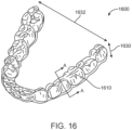
- FIG. 16 in orthodontic aligner 1600 is depicted.
- the orthodontic aligner 1600 may include a plurality of tooth receiving cavity 1610.
- the orthodontic aligner 1600 may be fabricated using additive manufacturing techniques such as those described herein.
- the additive manufacturing techniques described herein for reducing warpage and stress the fabricated part are well suited for devices having a low aspect ratio wherein the height along a build direction 1630 such as the Z axis is greater than the cross-sectional size 1632 of the device in an X - Y plane parallel to the build plate.
- the aspect ratio may be less than 0.25 (the height being one-fourth of the cross-sectional size), less than 0.2, less than 0.15, less than 0.1, or less than 0.05.
- the cross-sectional size may be a greatest distance between locations of the device within an X - Y plane.
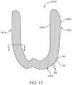
- FIG. 17 depicts a cross-section of the orthodontic aligner 1600 of FIG. 16 taken along A-A of a tooth receiving cavity 1610.
- the tooth receiving cavity 1610 includes a buccal sidewall 1620 a lingual sidewall 1614 and an occlusal wall 1616. Each sidewall includes an outward facing surface 1620 and an inward facing surface 1622.
- the cross-section depicted in FIG. 17 shows how the internal structure or infill may be formed or cured such that the material reaches is green strength.
- the tooth receiving cavity structure is formed using one or more of the masks discussed above. For example, the mask 40 depicted in FIG. 11 .
- the first areas 42 of each layer form columns 46 of green strength material within the structure of the aligner 1600 while the second areas 44 form portions of uncured or less cured resin between the columns 46.
- the columns may intersect the outer surfaces of the structure, such as the outward facing surface 1620 and the inward facing surface 1622.
- one or more of the infill columns 46 may begin at a first end on an external surface of the aligner and end at a second end on an external surface of the aligner.
- the orthodontic aligner 1600 is formed such that the lessor uncured volumes of resin corresponding to second areas 44 are held within the aligner between its external surfaces.
- the aligner may be subjected to a secondary curing process wherein the uncured material or resin corresponding to the areas 44 are cured along with the first areas 42 to an ultimate or final strength.
- FIG. 18 shows a cross section of the aligner along line B-B of FIG. 17 .
- the cross-section of the aligner 1600 shows a single layer of the aligner in Annex light plane parallel to the plane of a build platform on which the aligner 1600 is formed.
- the infill pattern 1624 may be similar to the mask 40 shown in FIG. 11 .
- the cured or green strength portions of the aligner are represented by first areas 42 and perimeters 1620 and 1622 that represent the outer or external surfaces of the aligner.
- first areas 42 may be intersected by the perimeters 1620, 1622.
- first area 48 is intersected by perimeters 1620 such that the first area 48 and the perimeters 1620 are continuous with each other.
- FIG. 19 shows a method 1900 for fabricating devices described herein.
- a three-dimensional model of the device such as an orthodontic device, is sliced into a plurality of layers. Slicing process divides the three-dimensional model into a plurality of two-dimensional layers each representing a portion of the height of the device represented by the three-dimensional model. For example, if a layer height is 10 ⁇ m then each layer would represent a 10 ⁇ m thick portion of the device.
- a first mask for a first of the plurality of layers is determined.
- a mask may be a two-dimensional, planar, representation of the cross-section of the device at a particular layer height. For a first layer of a model divided into 10 ⁇ m layer heights, a first layer may represent the cross-sectional structure of the device at a height between zero and 10 ⁇ m.
- a first mask may include a projected image of an external perimeter and an infill for a first curing operation for first areas of the first layer.
- a light energy dose and radiation strength may be determined for curing first areas of the device within the first layer. The light energy dose may be sufficient to cure a resin to its green strength and adhere the resin to the build plate. For subsequent layers the light energy dose may be sufficient to cure the resin to its green strength and adhere the resin to the previously cured layer.
- a second mask for the first layer of the plurality of layers be determined.
- the second mask may include a projected image of an infill for a second curing operation for second areas of the first layer.
- a second mask may include the perimeters, the first areas, and the second areas.
- a light energy dose and radiation strength may be determined for curing second areas of the device within the first layer.
- the light energy dose may be less than sufficient to cure a resin to its green strength.
- the curing dose provided during exposure of the first mask may be insufficient for the material to reach its green strength, however the first areas may be cured to their green strength upon receiving a second dose according to the second mask that includes a mask of the first areas, the second areas, and the perimeters.
- step 1930 the process may repeat the steps 1920 and 1930 for each of the layers of the plurality of layers of the three-dimensional model.
- instructions performing the plurality of layers may be output.
- Outputting the instructions may include storing the instructions or sending them to a fabrication machine, such as an additive manufacturing machine.
- a first layer of the plurality of layers of a device is cured using the first mask for the first dose.
- the first layer of the plurality of layers of the device is cured using the second mask at the second dose. Blocks 1950 and 1960 may be repeated for each of the plurality of layers of the device.
- a postprocessing or secondary curing process may occur.
- the device may be subject to a secondary curing process by which the resin in the device including both the green strength rather than resin and the less than green strength resin are cured to their final or ultimate strength.
- the additive manufacturing device 100 comprises a print head 102, such as a projector, and a build platform 104.
- the additive manufacturing device 100 comprises a processor 106, which includes a central processing unit (CPU) 108 and memory 110.
- the processor 106 can be configured with instructions to directly fabricate the appliance, as described herein.
- the instructions may comprise instructions to directly fabricate each of the plurality of layers along a direction of deposition in order to form the precursor appliance, as described herein.
- the print head 102 prints each of the plurality of layers and the separation distance between the print head 102 and the build platform 104 increases.
- the printhead may be a projector the projected light according to the masks discussed herein.
- FIG. 14 shows the additive manufacturing device 100 in a vertical orientation with a print head 102 located above a build platform 104
- the print head 102 can be located beneath the build platform 104.
- the direct fabrication process forms a single planar layer at a time that is approximately parallel to the build platform 104.
- the print head 102 may move away from the build platform 104 and a new layer is formed.
- the build platform 104 may move away from the print head 102.
- Each successive layer is built on the previous layer, for example on top of or beneath the previous layer.
- the additive manufacturing device 100 100 is shown in a vertical orientation, other orientations can be used to one or more of the components as described herein, for example horizontal or oblique orientations.
- FIG. 15 shows a schematic of a method 200 for manufacturing a dental device.
- direct fabrication configuration is selected to directly fabricate a plurality of layers of resin to form a body having a lower substantially planar surface and an upper surface.
- a plurality of layers are directly fabricated with each of the plurality of layers cured to have a similar amount of polymer cross-linking.
- a plurality of layers our directly fabricated with a first layer of the substantially planar surface and a second layer spaced from the first layer, in which each of the first layer and the second layer has an amount of polymer cross-linking greater than an amount of polymer cross-linking of a plurality of inner layers between the first layer and the second layer.
- a plurality of layers are directly fabricated with an increased dimension of the body in the direction of potential warping, so as to decrease deformation, e.g. in the Z direction as described herein.
- a plurality of layers are directly fabricated with the lower surface comprising a pattern of platforms defined with a plurality of grooves in the substantially planar surface.
- FIG. 15 shows a method of manufacturing a dental device, in accordance with some embodiments, a person of ordinary skill in the art will recognize many adaptations and variations. For example, the steps can be performed in a different order, some of the steps repeated and some of the steps removed.
- computing devices and systems described and/or illustrated herein broadly represent any type or form of computing device or system capable of executing computer-readable instructions, such as those contained within the modules described herein.
- these computing device(s) may each comprise at least one memory device and at least one physical processor.
- memory or “memory device,” as used herein, generally represents any type or form of volatile or non-volatile storage device or medium capable of storing data and/or computer-readable instructions.
- a memory device may store, load, and/or maintain one or more of the modules described herein.
- Examples of memory devices comprise, without limitation, Random Access Memory (RAM), Read Only Memory (ROM), flash memory, Hard Disk Drives (HDDs), Solid-State Drives (SSDs), optical disk drives, caches, variations or combinations of one or more of the same, or any other suitable storage memory.
- processor or "physical processor,” as used herein, generally refers to any type or form of hardware-implemented processing unit capable of interpreting and/or executing computer-readable instructions.
- a physical processor may access and/or modify one or more modules stored in the above-described memory device.
- Examples of physical processors comprise, without limitation, microprocessors, microcontrollers, Central Processing Units (CPUs), Field-Programmable Gate Arrays (FPGAs) that implement softcore processors, Application-Specific Integrated Circuits (ASICs), portions of one or more of the same, variations or combinations of one or more of the same, or any other suitable physical processor.
- the method steps described and/or illustrated herein may represent portions of a single application.
- one or more of these steps may represent or correspond to one or more software applications or programs that, when executed by a computing device, may cause the computing device to perform one or more tasks, such as the method step.
- one or more of the devices described herein may transform data, physical devices, and/or representations of physical devices from one form to another.
- one or more of the devices recited herein may receive image data of a sample to be transformed, transform the image data, output a result of the transformation to determine a 3D process, use the result of the transformation to perform the 3D process, and store the result of the transformation to produce an output image of the sample.
- one or more of the modules recited herein may transform a processor, volatile memory, non-volatile memory, and/or any other portion of a physical computing device from one form of computing device to another form of computing device by executing on the computing device, storing data on the computing device, and/or otherwise interacting with the computing device.
- computer-readable medium generally refers to any form of device, carrier, or medium capable of storing or carrying computer-readable instructions.
- Examples of computer-readable media comprise, without limitation, transmission-type media, such as carrier waves, and non-transitory-type media, such as magnetic-storage media (e.g., hard disk drives, tape drives, and floppy disks), optical-storage media (e.g., Compact Disks (CDs), Digital Video Disks (DVDs), and BLU-RAY disks), electronic-storage media (e.g., solid-state drives and flash media), and other distribution systems.
- transmission-type media such as carrier waves
- non-transitory-type media such as magnetic-storage media (e.g., hard disk drives, tape drives, and floppy disks), optical-storage media (e.g., Compact Disks (CDs), Digital Video Disks (DVDs), and BLU-RAY disks), electronic-storage media (e.g., solid-state drives and flash media),
- the processor as disclosed herein can be configured with instructions to perform any one or more steps of any method as disclosed herein.
Landscapes
- Engineering & Computer Science (AREA)
- Health & Medical Sciences (AREA)
- Materials Engineering (AREA)
- Chemical & Material Sciences (AREA)
- Manufacturing & Machinery (AREA)
- Oral & Maxillofacial Surgery (AREA)
- Animal Behavior & Ethology (AREA)
- Veterinary Medicine (AREA)
- Public Health (AREA)
- Dentistry (AREA)
- Epidemiology (AREA)
- Life Sciences & Earth Sciences (AREA)
- General Health & Medical Sciences (AREA)
- Optics & Photonics (AREA)
- Physics & Mathematics (AREA)
- Mechanical Engineering (AREA)
- Toxicology (AREA)
- General Engineering & Computer Science (AREA)
- Dental Preparations (AREA)
Claims (13)
- Procédé (200) de fabrication d'un dispositif oral (10), comprenant :la fabrication directe d'une pluralité de couches de résine photopolymère pour former un corps (16) comprenant une surface inférieure sensiblement plane et une surface supérieure ; etla surface inférieure plane étant fabriquée directement sur une plate-forme de construction, et au moins une première couche de la pluralité de couches étant durcie avec une première dose à une première résistance et au moins une deuxième couche de la pluralité de couches étant durcie avec une deuxième dose à une deuxième résistance afin d'empêcher le gauchissement du corps, une première couche sur la surface plane et une deuxième couche sur la surface supérieure étant directement fabriquées avec une quantité de réticulation de polymère supérieure à la quantité de réticulation de polymère d'une pluralité de couches intérieures entre la première couche et la deuxième couche, la quantité de réticulation étant commandée par la quantité d'énergie lumineuse utilisée pour durcir les couches.
- Procédé selon la revendication 1, le dispositif oral comprenant en outre au moins une attache (12) et au moins un support (14) couplant l'attache (12) au corps (16), le procédé comprenant en outre la fabrication directe d'une pluralité de couches de support pour former le support (14) et d'une pluralité de couches d'attache pour former l'attache (12).
- Procédé selon la revendication 1 ou selon la revendication 2, comprenant en outre la fabrication directe de la première couche et de la deuxième couche avec la même quantité de réticulation de polymère.
- Procédé selon l'une quelconque des revendications précédentes, comprenant en outre la fabrication directe de chaque couche de la pluralité intérieure de couches avec la même quantité de réticulation de polymère.
- Procédé selon l'une quelconque des revendications précédentes, le corps ayant une largeur, une longueur et une épaisseur, l'épaisseur étant au moins 0,25 fois la longueur du corps.
- Procédé selon l'une quelconque des revendications précédentes, comprenant en outre la fabrication directe de la surface inférieure avec un motif de plates-formes défini par une pluralité de rainures dans la surface.
- Procédé selon la revendication 6, le motif comprenant un ou plusieurs motifs parmi un motif de damier, un motif de tuile, ou un motif de bandes.
- Procédé selon l'une quelconque des revendications précédentes, comprenant en outre la fabrication directe des plates-formes pour avoir une zone comprise entre vingt-cinq pour cent et soixante-quinze pour cent d'une zone délimitée par un périmètre de la pluralité de plates-formes.
- Procédé selon la revendication 6, comprenant en outre la fabrication directe des plates-formes pour avoir une conicité qui s'élargit à partir d'une face d'une plate-forme vers la surface supérieure.
- Procédé selon la revendication 6, la surface inférieure ayant un motif comprenant des zones de résine ayant une quantité élevée de réticulation de polymère et des zones de résine ayant une quantité plus faible de réticulation de polymère.
- Procédé selon la revendication 10, le motif comprenant un ou plusieurs motifs parmi un motif de damier, un motif de tuile, ou un motif de bandes.
- Système de fabrication directe configuré pour fabriquer un dispositif oral conformément au procédé selon l'une quelconque des revendications 1 à 11.
- Programme informatique comprenant des instructions pour la mise en œuvre d'un procédé selon l'une quelconque des revendications 1 à 11.
Priority Applications (1)
| Application Number | Priority Date | Filing Date | Title |
|---|---|---|---|
| EP25151687.8A EP4537787A3 (fr) | 2019-07-29 | 2020-07-29 | Systèmes et procédé de fabrication additive de dispositifs dentaires à l'aide de résines photopolymères |
Applications Claiming Priority (2)
| Application Number | Priority Date | Filing Date | Title |
|---|---|---|---|
| US201962879845P | 2019-07-29 | 2019-07-29 | |
| PCT/US2020/044094 WO2021021948A1 (fr) | 2019-07-29 | 2020-07-29 | Systèmes et procédé de fabrication additive de dispositifs dentaires à l'aide de résines photopolymères |
Related Child Applications (1)
| Application Number | Title | Priority Date | Filing Date |
|---|---|---|---|
| EP25151687.8A Division EP4537787A3 (fr) | 2019-07-29 | 2020-07-29 | Systèmes et procédé de fabrication additive de dispositifs dentaires à l'aide de résines photopolymères |
Publications (3)
| Publication Number | Publication Date |
|---|---|
| EP3990258A1 EP3990258A1 (fr) | 2022-05-04 |
| EP3990258C0 EP3990258C0 (fr) | 2025-01-15 |
| EP3990258B1 true EP3990258B1 (fr) | 2025-01-15 |
Family
ID=72087251
Family Applications (2)
| Application Number | Title | Priority Date | Filing Date |
|---|---|---|---|
| EP20757121.7A Active EP3990258B1 (fr) | 2019-07-29 | 2020-07-29 | Systèmes et procédé de fabrication additive de dispositifs dentaires à l'aide de résines photopolymères |
| EP25151687.8A Pending EP4537787A3 (fr) | 2019-07-29 | 2020-07-29 | Systèmes et procédé de fabrication additive de dispositifs dentaires à l'aide de résines photopolymères |
Family Applications After (1)
| Application Number | Title | Priority Date | Filing Date |
|---|---|---|---|
| EP25151687.8A Pending EP4537787A3 (fr) | 2019-07-29 | 2020-07-29 | Systèmes et procédé de fabrication additive de dispositifs dentaires à l'aide de résines photopolymères |
Country Status (4)
| Country | Link |
|---|---|
| US (2) | US12115719B2 (fr) |
| EP (2) | EP3990258B1 (fr) |
| CN (2) | CN120533941A (fr) |
| WO (1) | WO2021021948A1 (fr) |
Families Citing this family (35)
| Publication number | Priority date | Publication date | Assignee | Title |
|---|---|---|---|---|
| US8030588B2 (en) | 2006-10-26 | 2011-10-04 | Align Technology, Inc. | System and method for sorting items |
| US7748199B2 (en) | 2006-11-28 | 2010-07-06 | Align Technology, Inc. | System and method for packaging of mass-fabricated custom items |
| US7957824B2 (en) | 2007-03-02 | 2011-06-07 | Align Technology, Inc. | Method and system for providing automated high scale fabrication of custom items |
| US8776391B1 (en) | 2007-04-13 | 2014-07-15 | Align Technology, Inc. | System for post-processing orthodontic appliance molds |
| US8765031B2 (en) | 2009-08-13 | 2014-07-01 | Align Technology, Inc. | Method of forming a dental appliance |
| US9108338B2 (en) | 2011-04-13 | 2015-08-18 | Align Technology, Inc. | Methods and systems for thermal forming an object |
| US9403238B2 (en) | 2011-09-21 | 2016-08-02 | Align Technology, Inc. | Laser cutting |
| US9943386B2 (en) | 2014-05-21 | 2018-04-17 | Align Technology, Inc. | Mold with weakened areas |
| US10888395B2 (en) | 2016-10-28 | 2021-01-12 | Align Technology, Inc. | Mold and aligner with cut line markings |
| CN114274691A (zh) | 2017-04-04 | 2022-04-05 | 阿莱恩技术有限公司 | 在矫正器上喷墨打印的方法 |
| CN115043974A (zh) | 2017-06-30 | 2022-09-13 | 阿莱恩技术有限公司 | 通过图案化曝光而用单一树脂制成的3d打印复合物 |
| US10783629B2 (en) | 2017-09-29 | 2020-09-22 | Align Technology, Inc. | Aligner image based quality control system |
| WO2020102757A1 (fr) | 2018-11-16 | 2020-05-22 | Align Technology, Inc. | Détection de défauts d'objets tridimensionnels (3d) faisant appel à une machine |
| CN113795218B (zh) | 2019-01-03 | 2023-07-04 | 阿莱恩技术有限公司 | 利用稳健参数优化方法的自动矫治器设计 |
| US20200290262A1 (en) | 2019-03-15 | 2020-09-17 | Align Technology, Inc. | Thermoforming multiple aligners in parallel |
| WO2020198331A1 (fr) | 2019-03-25 | 2020-10-01 | Align Technology, Inc. | Supports structurés variés pour aligneurs/embouchures imprimés en 3d |
| US11295444B2 (en) | 2019-04-01 | 2022-04-05 | Align Technology, Inc. | Vision and geometric approaches to detect defects in dental appliances |
| US11511485B2 (en) | 2019-04-02 | 2022-11-29 | Align Technology, Inc. | 3D printed objects with selective overcure regions |
| US11975463B2 (en) | 2019-12-11 | 2024-05-07 | AlignTechnology, Inc. | Attachments for handling and tracking fabricated custom objects |
| CN116568238A (zh) | 2020-10-09 | 2023-08-08 | 阿莱恩技术有限公司 | 多材料牙科设备及其制造技术 |
| US11958248B2 (en) | 2020-11-18 | 2024-04-16 | Align Technology, Inc. | Components with geometrical features to facilitate post-fabrication cleaning |
| US11897181B2 (en) | 2021-06-14 | 2024-02-13 | Align Technology, Inc. | Dynamic thermoforming of dental appliances |
| US12053925B2 (en) | 2021-10-14 | 2024-08-06 | Align Technology, Inc. | Recoating system including multiple blades |
| US12319002B2 (en) | 2021-10-28 | 2025-06-03 | Align Technology, Inc. | Systems for post-processing additively manufactured objects |
| US12263620B2 (en) | 2021-11-23 | 2025-04-01 | Align Technology, Inc. | Orthodontic aligner manufacturing and quality assessment system |
| US12544201B2 (en) | 2022-02-01 | 2026-02-10 | Align Technology, Inc. | Mold arch reinforcement and labeling for dental appliance manufacturing |
| US20230264428A1 (en) | 2022-02-23 | 2023-08-24 | Align Technology, Inc. | Indirect temperature monitoring for additive manufacturing |
| US20240033046A1 (en) * | 2022-07-29 | 2024-02-01 | SOVE, Inc. | Dental Device |
| WO2024040029A2 (fr) | 2022-08-15 | 2024-02-22 | Align Technology, Inc. | Procédés de production d'objets fabriqués de manière additive ayant des propriétés hétérogènes |
| EP4590489A2 (fr) | 2022-09-22 | 2025-07-30 | Cubicure GmbH | Plateformes de construction modulaires pour fabrication additive |
| WO2024092097A1 (fr) | 2022-10-26 | 2024-05-02 | Align Technology, Inc. | Systèmes de fabrication additive à substrats fixes |
| CN120112243A (zh) | 2022-10-26 | 2025-06-06 | 阿莱恩技术有限公司 | 具有机械互锁元件的材料和增材制造物品 |
| CN120225339A (zh) | 2022-11-01 | 2025-06-27 | 阿莱恩技术有限公司 | 用于增材制造的预制支撑结构和/或覆盖物 |
| BR102023000732A2 (pt) * | 2023-01-13 | 2024-01-30 | Do Rozario De Azevedo Mendes Lemos Maria | Dispositivo multi-alinhador ortodôntico envelope |
| WO2024182521A1 (fr) | 2023-02-28 | 2024-09-06 | Align Technology, Inc. | Additifs pour résines polymères d'impression 3d |
Family Cites Families (87)
| Publication number | Priority date | Publication date | Assignee | Title |
|---|---|---|---|---|
| US5965079A (en) * | 1995-04-25 | 1999-10-12 | 3D Systems, Inc. | Method and apparatus for making a three-dimensional object by stereolithography |
| US5204055A (en) * | 1989-12-08 | 1993-04-20 | Massachusetts Institute Of Technology | Three-dimensional printing techniques |
| US5868138A (en) | 1993-04-13 | 1999-02-09 | Silent Knight Ventures, Inc. | Dental appliance for treatment of snoring and obstructive sleep apnea |
| US5975893A (en) | 1997-06-20 | 1999-11-02 | Align Technology, Inc. | Method and system for incrementally moving teeth |
| US6322728B1 (en) * | 1998-07-10 | 2001-11-27 | Jeneric/Pentron, Inc. | Mass production of dental restorations by solid free-form fabrication methods |
| US7802987B1 (en) | 1999-12-17 | 2010-09-28 | Align Technology, Inc. | Methods and systems for lubricating dental appliances |
| US7245977B1 (en) | 2000-07-20 | 2007-07-17 | Align Technology, Inc. | Systems and methods for mass customization |
| US7092784B1 (en) | 2000-07-28 | 2006-08-15 | Align Technology | Systems and methods for forming an object |
| US6497574B1 (en) | 2000-09-08 | 2002-12-24 | Align Technology, Inc. | Modified tooth positioning appliances and methods and systems for their manufacture |
| JP4633297B2 (ja) * | 2000-12-05 | 2011-02-16 | 大日本印刷株式会社 | 凹凸パターン層の製造方法、およびこの方法を用いて製造される液晶ディスプレイおよびカラーフィルタ |
| US6749414B1 (en) | 2001-04-30 | 2004-06-15 | Stratasys, Inc. | Extrusion apparatus for three-dimensional modeling |
| US20040243361A1 (en) | 2002-08-19 | 2004-12-02 | Align Technology, Inc. | Systems and methods for providing mass customization |
| US7087109B2 (en) | 2002-09-25 | 2006-08-08 | Z Corporation | Three dimensional printing material system and method |
| EP2465464B1 (fr) | 2002-10-03 | 2018-08-22 | Align Technology, Inc. | Procédé de préparation d'un modèle physique |
| JP4140891B2 (ja) | 2003-01-15 | 2008-08-27 | ナブテスコ株式会社 | 光学的立体造形方法および装置 |
| WO2004087000A1 (fr) | 2003-04-03 | 2004-10-14 | Cadent Ltd. | Procede et systeme de fabrication d'une chape dentaire et chape dentaire ainsi fabriquee |
| US7648360B2 (en) | 2003-07-01 | 2010-01-19 | Align Technology, Inc. | Dental appliance sequence ordering system and method |
| US7261533B2 (en) | 2003-10-21 | 2007-08-28 | Align Technology, Inc. | Method and apparatus for manufacturing dental aligners |
| US7481647B2 (en) | 2004-06-14 | 2009-01-27 | Align Technology, Inc. | Systems and methods for fabricating 3-D objects |
| US7641828B2 (en) | 2004-10-12 | 2010-01-05 | Align Technology, Inc. | Methods of making orthodontic appliances |
| US20060127857A1 (en) | 2004-12-14 | 2006-06-15 | Frank Zhenhuan Liu | Producing non-interfering tooth models on a base |
| US7335024B2 (en) | 2005-02-03 | 2008-02-26 | Align Technology, Inc. | Methods for producing non-interfering tooth models |
| US20060127860A1 (en) | 2004-12-14 | 2006-06-15 | Huafeng Wen | Producing a base for accurately receiving dental tooth models |
| US20060127859A1 (en) | 2004-12-14 | 2006-06-15 | Huafeng Wen | Producing a physical toothmodel compatible with a physical dental arch model |
| US20060093982A1 (en) | 2004-11-02 | 2006-05-04 | Huafeng Wen | Method and apparatus for manufacturing and constructing a dental aligner |
| US7435084B2 (en) | 2004-12-14 | 2008-10-14 | Align Technology, Inc. | System and methods for casting physical tooth model |
| US20070092853A1 (en) | 2005-10-24 | 2007-04-26 | Liu Frank Z | Multi-layer casting methods and devices |
| US20060093987A1 (en) | 2004-11-02 | 2006-05-04 | Huafeng Wen | Producing an adjustable physical dental arch model |
| US20060127850A1 (en) | 2004-12-14 | 2006-06-15 | Huafeng Wen | Accurately producing a base for physical dental arch model |
| US7922490B2 (en) | 2004-12-14 | 2011-04-12 | Align Technology, Inc. | Base for physical dental arch model |
| US8636513B2 (en) | 2004-12-14 | 2014-01-28 | Align Technology, Inc. | Fabricating a base compatible with physical tooth models |
| US20060127858A1 (en) | 2004-12-14 | 2006-06-15 | Huafeng Wen | Producing accurate base for a dental arch model |
| US20060093993A1 (en) | 2004-11-02 | 2006-05-04 | Huafeng Wen | Producing a base for physical dental arch model |
| US20060199145A1 (en) | 2005-03-07 | 2006-09-07 | Liu Frank Z | Producing physical dental arch model having individually adjustable tooth models |
| US7384266B2 (en) | 2004-11-02 | 2008-06-10 | Align Technology, Inc. | Method and apparatus for manufacturing and constructing a physical dental arch model |
| US6976627B1 (en) | 2004-11-12 | 2005-12-20 | Align Technology, Inc. | Identification of units in customized production |
| US7236842B2 (en) | 2004-12-02 | 2007-06-26 | Cadent Ltd. | System and method for manufacturing a dental prosthesis and a dental prosthesis manufactured thereby |
| US20060172250A1 (en) | 2005-02-03 | 2006-08-03 | Huafeng Wen | Inelligent tracking of dental devices |
| US7819659B2 (en) | 2005-04-25 | 2010-10-26 | Align Technology, Inc. | System for organizing dental aligners |
| US7831322B2 (en) | 2005-03-07 | 2010-11-09 | Align Technology, Inc. | Producing wrinkled dental aligner for dental treatment |
| US7476100B2 (en) | 2005-05-17 | 2009-01-13 | Align Technology, Inc. | Guide apparatus and methods for making tooth positioning appliances |
| US20080083348A1 (en) | 2006-01-31 | 2008-04-10 | Align Technology, Inc. | Dual-chamber package for preparing alginate impression paste |
| US7472789B2 (en) | 2006-03-03 | 2009-01-06 | Align Technology, Inc. | Container for transporting and processing three-dimensional dentition models |
| US20070243502A1 (en) | 2006-04-17 | 2007-10-18 | Huafeng Wen | Digitization of target dental arch model |
| DE102006019964C5 (de) * | 2006-04-28 | 2021-08-26 | Envisiontec Gmbh | Vorrichtung und Verfahren zur Herstellung eines dreidimensionalen Objekts mittels Maskenbelichtung |
| US8087932B2 (en) | 2006-10-03 | 2012-01-03 | Align Technology, Inc. | Correcting the position of teeth in dental arch model |
| US7711447B2 (en) | 2006-10-20 | 2010-05-04 | Align Technology, Inc. | System and method for automated generating of a cutting curve on a surface |
| US8030588B2 (en) | 2006-10-26 | 2011-10-04 | Align Technology, Inc. | System and method for sorting items |
| US7892474B2 (en) | 2006-11-15 | 2011-02-22 | Envisiontec Gmbh | Continuous generative process for producing a three-dimensional object |
| US7748199B2 (en) | 2006-11-28 | 2010-07-06 | Align Technology, Inc. | System and method for packaging of mass-fabricated custom items |
| US7604181B2 (en) | 2006-12-28 | 2009-10-20 | Align Technology, Inc. | System for processing mass-fabricated items with three-dimensional codes |
| US7957824B2 (en) | 2007-03-02 | 2011-06-07 | Align Technology, Inc. | Method and system for providing automated high scale fabrication of custom items |
| US8776391B1 (en) | 2007-04-13 | 2014-07-15 | Align Technology, Inc. | System for post-processing orthodontic appliance molds |
| US7840373B2 (en) | 2007-05-30 | 2010-11-23 | Align Technology, Inc. | System and method for selecting a location for marking placement |
| US7674422B2 (en) | 2007-07-10 | 2010-03-09 | Align Technology, Inc. | Reinforced thin-shell molds |
| US8019465B2 (en) | 2007-07-31 | 2011-09-13 | Align Technology, Inc. | System and methods for increasing efficiency in rapid prototyping processes |
| DK2052693T4 (da) | 2007-10-26 | 2021-03-15 | Envisiontec Gmbh | Proces og fri-formfabrikationssystem til at fremstille en tredimensionel genstand |
| US20090148814A1 (en) | 2007-12-10 | 2009-06-11 | Chunhua Li | Dentition modeling |
| US8326024B2 (en) | 2009-04-14 | 2012-12-04 | Global Filtration Systems | Method of reducing the force required to separate a solidified object from a substrate |
| US8765031B2 (en) | 2009-08-13 | 2014-07-01 | Align Technology, Inc. | Method of forming a dental appliance |
| US9108338B2 (en) | 2011-04-13 | 2015-08-18 | Align Technology, Inc. | Methods and systems for thermal forming an object |
| US9403238B2 (en) | 2011-09-21 | 2016-08-02 | Align Technology, Inc. | Laser cutting |
| US9511543B2 (en) | 2012-08-29 | 2016-12-06 | Cc3D Llc | Method and apparatus for continuous composite three-dimensional printing |
| WO2014126834A2 (fr) | 2013-02-12 | 2014-08-21 | Eipi Systems, Inc. | Procédé et appareil pour fabrication tridimensionnelle avec support de traversée |
| CA2904648C (fr) | 2013-03-12 | 2021-05-18 | Orange Maker LLC | Impression 3d utilisant l'accumulation en spirale |
| US9517113B2 (en) | 2013-09-17 | 2016-12-13 | Ortho-Tain, Inc. | Oral appliance, system and method for correcting class III problems of mandibular prognathism |
| US10537406B2 (en) | 2014-02-21 | 2020-01-21 | Align Technology, Inc. | Dental appliance with repositioning jaw elements |
| US9943991B2 (en) | 2014-05-21 | 2018-04-17 | Align Technology, Inc. | Mold with separable features |
| US9943386B2 (en) | 2014-05-21 | 2018-04-17 | Align Technology, Inc. | Mold with weakened areas |
| US10363116B2 (en) * | 2015-07-07 | 2019-07-30 | Align Technology, Inc. | Direct fabrication of power arms |
| US10959810B2 (en) | 2015-07-07 | 2021-03-30 | Align Technology, Inc. | Direct fabrication of aligners for palate expansion and other applications |
| US10391755B2 (en) * | 2015-10-23 | 2019-08-27 | Ricoh Company, Ltd. | Solid freeform fabrication material set, method of fabricating solid freeform object, method of fabricating dental prosthesis, and device for fabricating solid freeform object |
| AT518101B1 (de) | 2015-12-17 | 2018-05-15 | Stadlmann Klaus | Verfahren zum Erzeugen eines dreidimensionalen Gegenstands |
| CN109311225B (zh) | 2016-06-20 | 2021-07-16 | B9创造有限责任公司 | 一种用于减少三维增材制造生产时间的系统和方法 |
| US10888395B2 (en) | 2016-10-28 | 2021-01-12 | Align Technology, Inc. | Mold and aligner with cut line markings |
| DE102016224060A1 (de) * | 2016-12-02 | 2018-06-07 | Siemens Aktiengesellschaft | Verfahren zur additiven Herstellung eines Bauteils mit Stützstruktur und reduzierter Energiedichte |
| CN114274691A (zh) | 2017-04-04 | 2022-04-05 | 阿莱恩技术有限公司 | 在矫正器上喷墨打印的方法 |
| CN115043974A (zh) | 2017-06-30 | 2022-09-13 | 阿莱恩技术有限公司 | 通过图案化曝光而用单一树脂制成的3d打印复合物 |
| US10783629B2 (en) | 2017-09-29 | 2020-09-22 | Align Technology, Inc. | Aligner image based quality control system |
| PL3620131T3 (pl) | 2018-09-07 | 2021-10-18 | Align Technology, Inc. | Aparat do korekcji zgryzu przystosowany do udoskonalonego znakowania laserowego |
| US11420362B2 (en) | 2018-10-31 | 2022-08-23 | Align Technology, Inc. | Mechanisms to automate removal of aligner from mold |
| WO2020102757A1 (fr) | 2018-11-16 | 2020-05-22 | Align Technology, Inc. | Détection de défauts d'objets tridimensionnels (3d) faisant appel à une machine |
| CN113795218B (zh) | 2019-01-03 | 2023-07-04 | 阿莱恩技术有限公司 | 利用稳健参数优化方法的自动矫治器设计 |
| US20200290262A1 (en) | 2019-03-15 | 2020-09-17 | Align Technology, Inc. | Thermoforming multiple aligners in parallel |
| WO2020198331A1 (fr) | 2019-03-25 | 2020-10-01 | Align Technology, Inc. | Supports structurés variés pour aligneurs/embouchures imprimés en 3d |
| US11295444B2 (en) | 2019-04-01 | 2022-04-05 | Align Technology, Inc. | Vision and geometric approaches to detect defects in dental appliances |
| US11511485B2 (en) | 2019-04-02 | 2022-11-29 | Align Technology, Inc. | 3D printed objects with selective overcure regions |
-
2020
- 2020-07-29 EP EP20757121.7A patent/EP3990258B1/fr active Active
- 2020-07-29 US US16/942,330 patent/US12115719B2/en active Active
- 2020-07-29 CN CN202510700140.8A patent/CN120533941A/zh active Pending
- 2020-07-29 EP EP25151687.8A patent/EP4537787A3/fr active Pending
- 2020-07-29 WO PCT/US2020/044094 patent/WO2021021948A1/fr not_active Ceased
- 2020-07-29 CN CN202080055736.2A patent/CN114206589B/zh active Active
-
2024
- 2024-09-16 US US18/886,729 patent/US20250010541A1/en active Pending
Also Published As
| Publication number | Publication date |
|---|---|
| WO2021021948A1 (fr) | 2021-02-04 |
| US12115719B2 (en) | 2024-10-15 |
| EP3990258A1 (fr) | 2022-05-04 |
| CN120533941A (zh) | 2025-08-26 |
| EP3990258C0 (fr) | 2025-01-15 |
| EP4537787A2 (fr) | 2025-04-16 |
| US20250010541A1 (en) | 2025-01-09 |
| CN114206589B (zh) | 2025-06-06 |
| EP4537787A3 (fr) | 2025-07-23 |
| US20210030516A1 (en) | 2021-02-04 |
| CN114206589A (zh) | 2022-03-18 |
Similar Documents
| Publication | Publication Date | Title |
|---|---|---|
| EP3990258B1 (fr) | Systèmes et procédé de fabrication additive de dispositifs dentaires à l'aide de résines photopolymères | |
| US20250178276A1 (en) | Overcure regions for 3d printed objects in dentistry | |
| US12465459B2 (en) | Direct fabrication of orthodontic appliances with elastic regions | |
| US20250381711A1 (en) | Manufacturing a shell using a mold | |
| US20260069385A1 (en) | Dental appliances with interproximal engagement structures | |
| US12226280B2 (en) | Direct fabrication of orthodontic appliances with 4D printing | |
| US12263620B2 (en) | Orthodontic aligner manufacturing and quality assessment system | |
| US20210178639A1 (en) | Attachments for handling and tracking fabricated custom objects | |
| US20240269935A1 (en) | 3d printed objects with overcured support structures | |
| WO2014095872A1 (fr) | Matériaux calibrés formés avec impression en trois dimensions | |
| US12605889B2 (en) | Modular build platforms for additive manufacturing | |
| JP4751144B2 (ja) | 造形データ作成システム、製造方法および造形データ作成プログラム | |
| US20240341921A1 (en) | Dental appliance occlusal element | |
| US20250276378A1 (en) | Attachment mechanisms for modular build platforms | |
| US20250108562A1 (en) | Methods for stabilizing additively manufactured objects | |
| WO2023096876A2 (fr) | Système d'évaluation de la qualité et de fabrication d'un dispositif d'alignement orthodontique |
Legal Events
| Date | Code | Title | Description |
|---|---|---|---|
| STAA | Information on the status of an ep patent application or granted ep patent |
Free format text: STATUS: UNKNOWN |
|
| STAA | Information on the status of an ep patent application or granted ep patent |
Free format text: STATUS: THE INTERNATIONAL PUBLICATION HAS BEEN MADE |
|
| PUAI | Public reference made under article 153(3) epc to a published international application that has entered the european phase |
Free format text: ORIGINAL CODE: 0009012 |
|
| STAA | Information on the status of an ep patent application or granted ep patent |
Free format text: STATUS: REQUEST FOR EXAMINATION WAS MADE |
|
| 17P | Request for examination filed |
Effective date: 20220131 |
|
| AK | Designated contracting states |
Kind code of ref document: A1 Designated state(s): AL AT BE BG CH CY CZ DE DK EE ES FI FR GB GR HR HU IE IS IT LI LT LU LV MC MK MT NL NO PL PT RO RS SE SI SK SM TR |
|
| DAV | Request for validation of the european patent (deleted) | ||
| DAX | Request for extension of the european patent (deleted) | ||
| RIC1 | Information provided on ipc code assigned before grant |
Ipc: A61C 7/08 20060101ALI20240630BHEP Ipc: B29C 64/286 20170101ALI20240630BHEP Ipc: B33Y 10/00 20150101ALI20240630BHEP Ipc: B33Y 80/00 20150101ALI20240630BHEP Ipc: B29C 64/129 20170101AFI20240630BHEP |
|
| GRAP | Despatch of communication of intention to grant a patent |
Free format text: ORIGINAL CODE: EPIDOSNIGR1 |
|
| STAA | Information on the status of an ep patent application or granted ep patent |
Free format text: STATUS: GRANT OF PATENT IS INTENDED |
|
| INTG | Intention to grant announced |
Effective date: 20240812 |
|
| RIN1 | Information on inventor provided before grant (corrected) |
Inventor name: WEBBER, PETER Inventor name: COLE, MICHAEL CHRISTOPHER Inventor name: O'LEARY, SIOBHAN |
|
| GRAS | Grant fee paid |
Free format text: ORIGINAL CODE: EPIDOSNIGR3 |
|
| GRAA | (expected) grant |
Free format text: ORIGINAL CODE: 0009210 |
|
| STAA | Information on the status of an ep patent application or granted ep patent |
Free format text: STATUS: THE PATENT HAS BEEN GRANTED |
|
| AK | Designated contracting states |
Kind code of ref document: B1 Designated state(s): AL AT BE BG CH CY CZ DE DK EE ES FI FR GB GR HR HU IE IS IT LI LT LU LV MC MK MT NL NO PL PT RO RS SE SI SK SM TR |
|
| REG | Reference to a national code |
Ref country code: CH Ref legal event code: EP Ref country code: GB Ref legal event code: FG4D |
|
| REG | Reference to a national code |
Ref country code: DE Ref legal event code: R096 Ref document number: 602020044824 Country of ref document: DE |
|
| REG | Reference to a national code |
Ref country code: IE Ref legal event code: FG4D |
|
| U01 | Request for unitary effect filed |
Effective date: 20250206 |
|
| U07 | Unitary effect registered |
Designated state(s): AT BE BG DE DK EE FI FR IT LT LU LV MT NL PT RO SE SI Effective date: 20250213 |
|
| PG25 | Lapsed in a contracting state [announced via postgrant information from national office to epo] |
Ref country code: RS Free format text: LAPSE BECAUSE OF FAILURE TO SUBMIT A TRANSLATION OF THE DESCRIPTION OR TO PAY THE FEE WITHIN THE PRESCRIBED TIME-LIMIT Effective date: 20250415 |
|
| PG25 | Lapsed in a contracting state [announced via postgrant information from national office to epo] |
Ref country code: PL Free format text: LAPSE BECAUSE OF FAILURE TO SUBMIT A TRANSLATION OF THE DESCRIPTION OR TO PAY THE FEE WITHIN THE PRESCRIBED TIME-LIMIT Effective date: 20250115 |
|
| PG25 | Lapsed in a contracting state [announced via postgrant information from national office to epo] |
Ref country code: ES Free format text: LAPSE BECAUSE OF FAILURE TO SUBMIT A TRANSLATION OF THE DESCRIPTION OR TO PAY THE FEE WITHIN THE PRESCRIBED TIME-LIMIT Effective date: 20250115 |
|
| PGFP | Annual fee paid to national office [announced via postgrant information from national office to epo] |
Ref country code: GB Payment date: 20250605 Year of fee payment: 6 |
|
| PG25 | Lapsed in a contracting state [announced via postgrant information from national office to epo] |
Ref country code: IS Free format text: LAPSE BECAUSE OF FAILURE TO SUBMIT A TRANSLATION OF THE DESCRIPTION OR TO PAY THE FEE WITHIN THE PRESCRIBED TIME-LIMIT Effective date: 20250515 Ref country code: NO Free format text: LAPSE BECAUSE OF FAILURE TO SUBMIT A TRANSLATION OF THE DESCRIPTION OR TO PAY THE FEE WITHIN THE PRESCRIBED TIME-LIMIT Effective date: 20250415 |
|
| PG25 | Lapsed in a contracting state [announced via postgrant information from national office to epo] |
Ref country code: HR Free format text: LAPSE BECAUSE OF FAILURE TO SUBMIT A TRANSLATION OF THE DESCRIPTION OR TO PAY THE FEE WITHIN THE PRESCRIBED TIME-LIMIT Effective date: 20250115 |
|
| U20 | Renewal fee for the european patent with unitary effect paid |
Year of fee payment: 6 Effective date: 20250606 |
|
| PG25 | Lapsed in a contracting state [announced via postgrant information from national office to epo] |
Ref country code: GR Free format text: LAPSE BECAUSE OF FAILURE TO SUBMIT A TRANSLATION OF THE DESCRIPTION OR TO PAY THE FEE WITHIN THE PRESCRIBED TIME-LIMIT Effective date: 20250416 |
|
| PG25 | Lapsed in a contracting state [announced via postgrant information from national office to epo] |
Ref country code: SM Free format text: LAPSE BECAUSE OF FAILURE TO SUBMIT A TRANSLATION OF THE DESCRIPTION OR TO PAY THE FEE WITHIN THE PRESCRIBED TIME-LIMIT Effective date: 20250115 |
|
| PG25 | Lapsed in a contracting state [announced via postgrant information from national office to epo] |
Ref country code: CZ Free format text: LAPSE BECAUSE OF FAILURE TO SUBMIT A TRANSLATION OF THE DESCRIPTION OR TO PAY THE FEE WITHIN THE PRESCRIBED TIME-LIMIT Effective date: 20250115 |
|
| PG25 | Lapsed in a contracting state [announced via postgrant information from national office to epo] |
Ref country code: SK Free format text: LAPSE BECAUSE OF FAILURE TO SUBMIT A TRANSLATION OF THE DESCRIPTION OR TO PAY THE FEE WITHIN THE PRESCRIBED TIME-LIMIT Effective date: 20250115 |
|
| PLBE | No opposition filed within time limit |
Free format text: ORIGINAL CODE: 0009261 |
|
| STAA | Information on the status of an ep patent application or granted ep patent |
Free format text: STATUS: NO OPPOSITION FILED WITHIN TIME LIMIT |
|
| REG | Reference to a national code |
Ref country code: CH Ref legal event code: L10 Free format text: ST27 STATUS EVENT CODE: U-0-0-L10-L00 (AS PROVIDED BY THE NATIONAL OFFICE) Effective date: 20251126 |
|
| 26N | No opposition filed |
Effective date: 20251016 |
|
| REG | Reference to a national code |
Ref country code: CH Ref legal event code: H13 Free format text: ST27 STATUS EVENT CODE: U-0-0-H10-H13 (AS PROVIDED BY THE NATIONAL OFFICE) Effective date: 20260224 |
|
| PG25 | Lapsed in a contracting state [announced via postgrant information from national office to epo] |
Ref country code: CH Free format text: LAPSE BECAUSE OF NON-PAYMENT OF DUE FEES Effective date: 20250731 |