EP3990366B1 - Flaschenkasten mit originalitätsverschluss und verfahren zur sicherung von flaschen - Google Patents
Flaschenkasten mit originalitätsverschluss und verfahren zur sicherung von flaschen Download PDFInfo
- Publication number
- EP3990366B1 EP3990366B1 EP20832022.6A EP20832022A EP3990366B1 EP 3990366 B1 EP3990366 B1 EP 3990366B1 EP 20832022 A EP20832022 A EP 20832022A EP 3990366 B1 EP3990366 B1 EP 3990366B1
- Authority
- EP
- European Patent Office
- Prior art keywords
- bottle
- frame
- insert
- securing
- tamper
- Prior art date
- Legal status (The legal status is an assumption and is not a legal conclusion. Google has not performed a legal analysis and makes no representation as to the accuracy of the status listed.)
- Active
Links
Images








Classifications
-
- B—PERFORMING OPERATIONS; TRANSPORTING
- B65—CONVEYING; PACKING; STORING; HANDLING THIN OR FILAMENTARY MATERIAL
- B65D—CONTAINERS FOR STORAGE OR TRANSPORT OF ARTICLES OR MATERIALS, e.g. BAGS, BARRELS, BOTTLES, BOXES, CANS, CARTONS, CRATES, DRUMS, JARS, TANKS, HOPPERS, FORWARDING CONTAINERS; ACCESSORIES, CLOSURES, OR FITTINGS THEREFOR; PACKAGING ELEMENTS; PACKAGES
- B65D85/00—Containers, packaging elements or packages, specially adapted for particular articles or materials
- B65D85/30—Containers, packaging elements or packages, specially adapted for particular articles or materials for articles particularly sensitive to damage by shock or pressure
- B65D85/305—Bottle-crates
-
- B—PERFORMING OPERATIONS; TRANSPORTING
- B65—CONVEYING; PACKING; STORING; HANDLING THIN OR FILAMENTARY MATERIAL
- B65D—CONTAINERS FOR STORAGE OR TRANSPORT OF ARTICLES OR MATERIALS, e.g. BAGS, BARRELS, BOTTLES, BOXES, CANS, CARTONS, CRATES, DRUMS, JARS, TANKS, HOPPERS, FORWARDING CONTAINERS; ACCESSORIES, CLOSURES, OR FITTINGS THEREFOR; PACKAGING ELEMENTS; PACKAGES
- B65D25/00—Details of other kinds or types of rigid or semi-rigid containers
- B65D25/54—Inspection openings or windows
-
- B—PERFORMING OPERATIONS; TRANSPORTING
- B65—CONVEYING; PACKING; STORING; HANDLING THIN OR FILAMENTARY MATERIAL
- B65D—CONTAINERS FOR STORAGE OR TRANSPORT OF ARTICLES OR MATERIALS, e.g. BAGS, BARRELS, BOTTLES, BOXES, CANS, CARTONS, CRATES, DRUMS, JARS, TANKS, HOPPERS, FORWARDING CONTAINERS; ACCESSORIES, CLOSURES, OR FITTINGS THEREFOR; PACKAGING ELEMENTS; PACKAGES
- B65D55/00—Accessories for container closures not otherwise provided for
- B65D55/02—Locking devices; Means for discouraging or indicating unauthorised opening or removal of closure
-
- B—PERFORMING OPERATIONS; TRANSPORTING
- B65—CONVEYING; PACKING; STORING; HANDLING THIN OR FILAMENTARY MATERIAL
- B65D—CONTAINERS FOR STORAGE OR TRANSPORT OF ARTICLES OR MATERIALS, e.g. BAGS, BARRELS, BOTTLES, BOXES, CANS, CARTONS, CRATES, DRUMS, JARS, TANKS, HOPPERS, FORWARDING CONTAINERS; ACCESSORIES, CLOSURES, OR FITTINGS THEREFOR; PACKAGING ELEMENTS; PACKAGES
- B65D71/00—Bundles of articles held together by packaging elements for convenience of storage or transport, e.g. portable segregating carrier for plural receptacles such as beer cans or pop bottles; Bales of material
- B65D71/50—Bundles of articles held together by packaging elements for convenience of storage or transport, e.g. portable segregating carrier for plural receptacles such as beer cans or pop bottles; Bales of material comprising a plurality of articles held together only partially by packaging elements formed otherwise than by folding a blank
-
- B—PERFORMING OPERATIONS; TRANSPORTING
- B65—CONVEYING; PACKING; STORING; HANDLING THIN OR FILAMENTARY MATERIAL
- B65D—CONTAINERS FOR STORAGE OR TRANSPORT OF ARTICLES OR MATERIALS, e.g. BAGS, BARRELS, BOTTLES, BOXES, CANS, CARTONS, CRATES, DRUMS, JARS, TANKS, HOPPERS, FORWARDING CONTAINERS; ACCESSORIES, CLOSURES, OR FITTINGS THEREFOR; PACKAGING ELEMENTS; PACKAGES
- B65D81/00—Containers, packaging elements, or packages, for contents presenting particular transport or storage problems, or adapted to be used for non-packaging purposes after removal of contents
- B65D81/02—Containers, packaging elements, or packages, for contents presenting particular transport or storage problems, or adapted to be used for non-packaging purposes after removal of contents specially adapted to protect contents from mechanical damage
- B65D81/025—Containers made of sheet-like material and having a shape to accommodate contents
-
- B—PERFORMING OPERATIONS; TRANSPORTING
- B65—CONVEYING; PACKING; STORING; HANDLING THIN OR FILAMENTARY MATERIAL
- B65D—CONTAINERS FOR STORAGE OR TRANSPORT OF ARTICLES OR MATERIALS, e.g. BAGS, BARRELS, BOTTLES, BOXES, CANS, CARTONS, CRATES, DRUMS, JARS, TANKS, HOPPERS, FORWARDING CONTAINERS; ACCESSORIES, CLOSURES, OR FITTINGS THEREFOR; PACKAGING ELEMENTS; PACKAGES
- B65D2401/00—Tamper-indicating means
-
- B—PERFORMING OPERATIONS; TRANSPORTING
- B65—CONVEYING; PACKING; STORING; HANDLING THIN OR FILAMENTARY MATERIAL
- B65D—CONTAINERS FOR STORAGE OR TRANSPORT OF ARTICLES OR MATERIALS, e.g. BAGS, BARRELS, BOTTLES, BOXES, CANS, CARTONS, CRATES, DRUMS, JARS, TANKS, HOPPERS, FORWARDING CONTAINERS; ACCESSORIES, CLOSURES, OR FITTINGS THEREFOR; PACKAGING ELEMENTS; PACKAGES
- B65D2501/00—Containers having bodies formed in one piece
- B65D2501/24—Boxes or like containers with moulded compartments or partitions
- B65D2501/24006—Details relating to bottle crates
- B65D2501/24866—Other details
- B65D2501/24955—Means for inserting or extracting the bottles
- B65D2501/24974—Bottle extracting means
-
- B—PERFORMING OPERATIONS; TRANSPORTING
- B65—CONVEYING; PACKING; STORING; HANDLING THIN OR FILAMENTARY MATERIAL
- B65D—CONTAINERS FOR STORAGE OR TRANSPORT OF ARTICLES OR MATERIALS, e.g. BAGS, BARRELS, BOTTLES, BOXES, CANS, CARTONS, CRATES, DRUMS, JARS, TANKS, HOPPERS, FORWARDING CONTAINERS; ACCESSORIES, CLOSURES, OR FITTINGS THEREFOR; PACKAGING ELEMENTS; PACKAGES
- B65D2555/00—Accessories for container closures not otherwise provided for
- B65D2555/02—Locking devices; Means for discouraging or indicating unauthorised opening or removal of closure
- B65D2555/025—Applied tearing or cutting means, e.g. tear-strings
Definitions
- aspects of the present disclosure relate to an improved case or portions thereof for shipping and storing various products, including bottled liquids, and, more particularly, for improving the storage, transport, and protection of products such as beverage bottles.
- each individual bottle must be removed from the case.
- the handling of each bottle creates an opportunity to damage the bottle.
- legacy bottle cases do not have individual tamper-resistant mechanisms in place, and since each bottle in the case can be removed, a fraudster can tamper with the contents of the bottle case. For example, someone inspecting the bottles can replace a bottle with a different, less-valuable bottle.
- current methods do not provide an aesthetic system for displaying the bottles.
- a carboard case for example, is made to be an inexpensive shipping container that is discarded once opened. The wooden case requires tools to wedge open the lid, which can be easily damaged when being pried apart from the body of the case. What is needed, therefore, is a system that prevents tampering, provides bottle viewability, and maintains an aesthetic form for displaying the bottles.
- a tamper-proof case comprising a unibody frame constructed from a single piece of material.
- the unibody frame can comprise six sides and include one or more living hinges that allow the unibody frame to fold into a completed case.
- Various sides can be configured to receive panels.
- the frame can comprise a split-top lid with a self-locking mechanism with a tamper-proof pull tab for opening the lid.
- US 5,476,170 A describes a bottle carrier including a tubular structure including a base wall and a top portion disposed above the base wall, neck-gripping edges provided for the top portion to engage the underside of a peripheral neck projection of a bottle, and shoulder-gripping flaps provided for the base wall to engage and press down on the shoulder of the bottle.
- the top portion of the tubular structure has an upper aperture for receiving the neck of the bottle whereas the base wall has a lower aperture for receiving the shoulder of the bottle.
- the upper and lower apertures are disposed in vertical alignment with each other.
- EP 0108614 A2 describes a carrier for holding a plurality of articles which includes a shell formed from a blank of relatively thin printable sheet material folded to the shell form and maintained in the folded form by a moulded plastic frame bonded to the underside thereof, apertures in a main panel, reinforced by mouldings being provided allowing the shell to be applied open side down to bottles to engage under projections on the bottles so that shell will serve as a carrier for the bottles.
- aspects of the present disclosure address these concerns as well as other needs that will become apparent upon reading the description below in conjunction with the drawings. Briefly described, aspects of the present disclosure relate to an improved case or portions thereof for shipping and storing various products, including bottled liquids, and, more particularly, for improving the storage, transport, and protection of products such as beverage bottles.
- the present invention provides a tamper-proof bottle case as set out in claim 1 and a method for securing bottles as set out in claim 6.
- the tamper-proof bottle case comprises a frame having a top face, a bottom face, and four substantially horizontal side faces.
- the frame for the case can be a rectangular or a substantially rectangular prism.
- Each of these faces can be adapted to accept a panel to protect the contents within the frame.
- At least one of the panels can be transparent and/or provide an opening to both view and manipulate the bottles within the frame.
- the tamper-proof case includes additional features within the case that can support the bottles, protect the bottles, and provide tamper-resistance to ensure security of the bottle.
- These features include a top insert for supporting the neck of a bottle.
- the top insert is configured to be positioned proximate the top face of the frame.
- the top insert includes a series of elongated bottle holders.
- Each elongated bottle holder has an inner channel accepting the bottle neck and a perimeter surface surrounding the inner channel.
- Each elongated bottle holder includes a tab attached to the perimeter surface of the elongated bottle holder. This tab can create a security feature of the tamper-proof bottle case.
- the tab is configured to be pulled away from the elongated bottle holder such that the tab pulls with it a removable portion of the perimeter surface. Once the removable portion of the perimeter surface is removed, the bottle neck can be pulled from the elongated bottle holder.
- the top insert includes securing platforms positioned at the top end of the inner channels of the elongated bottle holders.
- a bottle neck can be placed within the inner channel of an elongated bottle holder, and at the top of the inner channel can be a securing platform that contacts the top of the bottle.
- the securing platform can be used to constrain the bottle from moving up and down within the tamper-proof bottle case, to apply slight axial pressure to the cork within the bottle, and to further support the bottle.
- the top insert can be manufactured substantially horizontal and can be folded to create the insert that is placed proximate the top face of the frame.
- the top insert can have a bottom level comprising the elongated bottle holders and a top level comprising the securing platforms.
- the securing platforms are substantially horizontal to the elongated bottle holders.
- the top insert can then be folded from the first, horizontal position into a second position. In the second position, the securing platforms are proximate the top end of the inner channels of respective elongated bottle holders.
- the additional features within a frame include a bottom insert for supporting the heel of a bottle.
- the bottom insert is positioned proximate the bottom face of the frame.
- the bottom insert includes a series of cups that accept the bottle heel.
- the bottom insert can additionally include raised lips at certain portions around the cups so as to increase the lift required to remove a bottle from the cups.
- the components of the frame can comprise wood, plastic, and the like or any combination thereof.
- the top insert and/or bottom insert can comprise pressed paper pulp, cardboard, plastic materials, and the like or any combination thereof.
- the panels can comprise wood, plastic, cardboard, nano crystalline cellulose cardboard, PVC, rubber, metal, cork, and the like or any other suitable material or combination of materials to provide protection for the contents within the tamper-proof case.
- the transparent panel can include glass, clear plastic materials (including but not limited to acrylic glass), and the like.
- FIG. 1 is a perspective view of example securing components for a tamper-proof bottle case, according to some embodiments of the present disclosure.
- FIG. 1 does not include an outer case or frame for a case.
- the figure shows example components that can be included within an outer case or frame for securing bottles. Accordingly, the components shown in FIG. 1 can be modular and used in a variety of outer cases or frames.
- the top insert 102 includes a tab 110.
- the tab 110 can be positioned proximate the perimeter surface 108 and attached to at least a portion of the perimeter surface 108.
- the tab 110 is configured to be used to remove a removable portion of the perimeter surface 108 such that the bottle 106 can be pulled laterally from the top insert 102.
- the removable portion is discussed in greater detail with reference to FIGs. 3 and 5 , for example.
- the top insert 102 includes securing platforms 112.
- the securing platforms 112 include material that contacts the top of the bottle 106.
- the full securing platforms 112 are not visible as they are placed inside the top insert 102 and proximate the top of the bottle 106.
- a top insert 102 can include notches 114.
- the notches 114 can meet or mate with components of a frame and/or case so as to prevent movement of the top insert 102.
- the notches 114 can meet with a tab of a frame and/or case to prevent lateral movement of the top insert 102.
- the securing components within a case include a bottom insert 116.
- the bottom insert 116 includes one or more cups 118 that can accept the heel of a bottle 106.
- the cups 118 can have a depth requiring a certain amount of lift on the bottle 106 to remove the bottle 106 from the cups 118.
- the cup 118 can be shaped according to the shape of the heel of the bottle 106 in which the cup 118 is holding. For example, if the heel of the bottle 106 is round (as shown), the cup 118 can be round, and if the heel of the bottle 106 is square, the cup 118 can be square. Any other shape of a cup 118 is contemplated and is possible with the presently disclosed systems.
- the cup 118 can create a snug fit for the bottle heel.
- the cup 118 can be smooth to allow the bottle to be rotated within the cup 118. This embodiment would allow a user to inspect the bottle 106 by rotating the bottle 106 without removing the bottle 106 from the bottom insert 116 or top insert 102.
- the cup 118 can comprise a friction-fit surface to prohibit the bottle 106 from rotating.
- the friction-fit surface also can provide additional padding and protection for the bottle 106.
- the friction-fit surface can include a rubber pad, rubber grommet, and/or the like.
- FIG. 1 depicts an embodiment with six bottles 106, which is in accordance with some embodiments. It is contemplated that three bottles 106 can be along one side of the top insert 102 and bottom insert 116, and another three bottles can be along another side of the inserts 102,116. However, the present disclosure is not limited to the construct shown in the figure. The systems described herein can equally apply to more or fewer bottles 106 than shown in the figure. It is also contemplated that the present disclosure can be used in a single-bottle construct.
- FIG. 2 is a perspective view of example securing components for a tamper-proof bottle case, according to some embodiments of the present disclosure.
- FIG. 2 depicts a top insert 102 and a bottom insert 116 configured to hold three bottles 106, which is in accordance with some embodiments.
- the systems described herein can be used for a variety of bottle sizes and shapes. For example, a beverage producer may wish to package and ship a magnum (1.5 liter) or larger bottle. In these scenarios, a three or fewer bottle 106 construct can help the producer lower the overall size and weight of the bottle case.
- FIG. 3 is a perspective view of an unfolded top insert 102, according to some embodiments of the present disclosure.
- the top insert 102 includes a first configuration and a second configuration.
- the first configuration is a substantially horizontal configuration, such as shown in FIG. 3 .
- the second configuration can be similar to the configurations shown in FIGs. 1 , 2 , 4, and 5 , for example.
- These two configurations can allow the top insert to be manufactured as a sheet and then folded into the final protecting insert to be placed atop a bottle 106.
- the components of the top insert 102 can be pressed into shape in a single sheet of, for example, cardboard or paper pulp. Once pressed and formed, the top insert 102 can be folded into the final configuration to protect the neck of a bottle 106.
- the top insert 102 can include a bottom level 302.
- the bottom level 302 of the unfolded top insert 102 can include the one or more elongated bottle holders 104.
- the one or more elongated bottle holders 104 have an inner channel 304 that can contact and accept the neck of a bottle. At one end of the inner channel 304 can be an orifice 306 in which the neck of the bottle is inserted.
- Each elongated bottle holder 104 can also include a removable portion 308.
- the removable portion 308 is a portion of the perimeter surface 108 surrounding the inner channel 304 that is configured to be removed upon a pulling of the tab 110.
- the bottom level 302 of the unfolded top insert 102 can also include one or more ramps 309 to add additional support for a top level of the unfolded top insert 102.
- the inner channels 304 can be smooth to allow the bottle to be rotated within the elongated bottle holder 104. This embodiment would allow a user to inspect the bottle 106 by rotating the bottle 106 without removing the bottle 106 from the top insert 102 or bottom insert 116.
- the inner channels 304 can include a friction-fit surface to prohibit the bottle 106 from rotating. The friction-fit surface also can provide additional padding and protection for the bottle 106.
- the friction-fit surface can include a rubber pad, rubber grommet, and/or the like.
- the top insert 102 can include a top level 310a,b.
- the top level can include two separate sides, a first side of the top level 310a and a second side of the top level 310b.
- the first side of the top level 310a can fold over from the horizontal position to a position proximate the elongated bottle holders 104
- the second side of the top level 310b can also fold over from the horizontal position to a position proximate the elongated bottle holders 104.
- the top level 310a,b is not two separate flanges but is a single flange that folds to a position proximate the elongated bottle holders 104.
- FIG. 3 provides arrows 350 showing the direction of folding the top insert 102 from the first configuration into the second configuration, e.g., the top level 310a,b can be folded upward and onto the bottom level 302 in the example embodiment.
- a top level 310a,b can include one or more securing platforms 112a,b, as shown in FIGs. 1-2 as securing platforms 112.
- one series of securing platforms 112a can be present on one side of the top level 310a
- another series of securing platforms 112b can be on the other side of the top level 310b.
- all securing platforms 112a,b can be disposed on the single top level 310a,b.
- the securing platforms 112a,b contact the top of a bottle when the top insert 102 is in a folded, second configuration. As described above, the securing platforms 112a,b can constrain the bottle from moving up the inner channels 304, thereby further securing the bottles in the top insert 102. It is also contemplated that the securing platforms 112a,b can be used to maintain pressure on a cork in the top of a bottle so as to prevent the cork from rising from the bottle during shipping and handling.
- a securing platform 112a,b can include a recess 312a,b that can be shaped to fit the top of the bottle.
- the recess 312a,b can be a half-circular recess that is shaped to fit one half of the top of the bottle, as shown in the figure.
- the recess 312a,b can be a full-circular recess to fit the top of the bottle.
- the recess 312a,b can be modified according to the dimensions of the particular bottle being stored in the tamper-proof case since, as will be appreciated by one of skill in the art, bottles can take many different shapes and sizes (e.g., piccolo or split (187.5 ml), demi or half (375 ml), standard (750 ml), magnum (1.5 L), double magnum (3.0 L), etc.).
- the top insert 102 can include a middle level 314.
- the middle level 314 can include one or more flanges that, when the top insert 102 is folded from the horizontal configuration to the final configuration, provide side support for the folded top insert 102.
- the middle level 314 can include end flanges 316 that can be folded to meet with the top level 310a,b when the top level 310a,b is folded over. These end flanges 316 can provide additional support and structural integrity to the top level 310a,b.
- the middle level 314 can also include side flanges 318 to provide additional support and structural integrity to the top level 310a,b.
- the side flanges 318 can be positioned between the bottom level 302 and the top level 310a,b (as shown in FIG. 3 ) such that a first fold is provided between the side flanges 318 and the bottom level 302, and a second fold is positioned between the side flanges 318 and the top level 310a,b.
- FIG. 4 is a perspective view of an example top insert 102, according to some embodiments of the present disclosure.
- FIG. 4 shows a top insert 102 in a second, final configuration after folding.
- the horizontal configuration of FIG. 3 can be folded into the embodiment shown in FIG. 4 .
- a top insert 102 can include securing-platform recesses 402 that extend from one side of the top level 310. These securing-platform recesses 402 can be present to decrease the material used in the top insert 102.
- the top insert 102 can be made by pressing a single sheet into the final form of the top level 310.
- the securing platforms 112 can be created by pressing the top insert 102 into a final form, thereby creating the securing-platform recesses 402.
- the securing-platform recesses 402 may not be present.
- the top level 310 is sealed to the bottom level 302. This sealing can provide security such that a bottle can be removed only by pulling the tab 110 to release a removable portion (e.g., removable portion 308 in FIG. 3 ) of the elongated bottle holder 104 to release the bottle.
- a removable portion e.g., removable portion 308 in FIG. 3
- the elongated bottle holders 104 can have a variety of shapes.
- the elongated bottle holders 104 in FIG. 4 have a perimeter surface 108 having a conical frustum shape, which is in accordance with some embodiments of the present disclosure.
- the removable portion of the perimeter surface 108 can be placed within the conical frustum shape.
- Other shapes are contemplated, for example, rectangular shapes, cylindrical shapes, and the like, and these embodiments are contemplated within the scope of this disclosure.
- FIG. 5 is a perspective view of an example top insert 102, according to some embodiments of the present disclosure.
- the perimeter surface 108 of an elongated bottle holder 104 can include a removable portion 308 that is flat, or planar.
- the perimeter surface 108 of the elongated bottle holder 104 can be substantially conical, round, cylindrical, and/or the like; the removable portion 308 connected to a tab 110, however, can be substantially planar or flat.
- a planar removable portion 308 can facilitate the tab's 110 ability to remove the removable portion 308 so as to create a smooth opening to remove the bottle.
- a planar removable portion 308 can comprise the same material as the non-planar part of the perimeter surface 108.
- a top insert 102 can be produced by pressing the top insert 102 into its shape. It is contemplated, therefore, that the planar removable portion 308 is merely formed as a planar part of the geometry of the pressed perimeter surface 108.
- the removable portion 308 can include perforations that allow the removable portion 308 to be removed from the elongated bottle holder 104 with a clean or straight edge.
- a planar removable portion 308 can be a separate material that is connected to the elongated bottle holder 104.
- top inserts 102 can include a removable portion 308 that is secured to the elongated bottle holder 104 with adhesive, tamper-evident tape, and/or the like to indicate whether the removable portion 308 has been removed from the top insert 102.
- Tamper-evident tape can include any tape known in the art used to indicate whether the tape has been removed, broken, or cut.
- tamper-evident tape can include wording that prohibits the tape from being realigned and reattached once removed. Tamper-evident tape also can include language similar to "check contents if seal is broken" and the like.
- FIG. 6 is a front view of a top insert 102 within a frame 602, according to some embodiments of the present disclosure.
- the top insert 102 can be inserted into a frame 602 that contains the components described herein and the one or more bottles 106.
- the frame 602 can be a substantially rectangular prism, as shown in the figure.
- the frame 602 can have six planar faces, including a top face 604, four substantially horizontal side faces 606 (one side face is in the foreground and another side face is in the background of this view), and a bottom face (not shown in the figure).
- the top insert 102 is proximate the top face 604. Each face can accept a panel to protect the contents within the frame 602. It is contemplated that one or more faces can include tabs 608 that provide an outward force on a panel so as to prevent the panel from vibrating or excessively moving during handling and transport.
- the frame 602 can be made to assemble around the components and one or more bottle 106 and thereafter be resistant to disassembly.
- one aspect of the present disclosure is to provide a tamper-proof case for bottles 106. It is contemplated that once a frame is assembled around the top insert 102 and bottles 106, the frame cannot be disassembled. In these embodiments, a customer wishing to remove the bottle 106 from the frame 602 can be required to pull the tab 110 and remove a removable portion of the elongated bottle holder 104.
- FIG. 7 depicts an embodiment wherein a removable portion (not shown in FIG. 7 as it has been removed) has been removed by pulling a tab 110.
- FIG. 8 is a detailed view of the top insert 102 inside a frame 602, according to some embodiments of the present disclosure.
- a frame 602 can include latches 802 that can accept a feature of a panel so as to secure the panel to the frame 602.
- FIG. 9 is a perspective view of an example bottom insert 116, according to some embodiments of the present disclosure.
- the components within a frame or case include a bottom insert 116.
- the bottom insert 116 can include one or more cups 118 that can accept the heel of a bottle.
- the cups 118 can have a depth that requires a certain amount of lift on the bottle to remove the bottle from the cups 118. It is contemplated that the cups 118 can have a depth of from about 1.0 cm to about 4.0 cm (e.g., from about 1.0 cm to about 2.0 cm; from about 1.5 cm to about 2.5 cm; from about 2.0 cm to about 3.0 cm; from about 2.5 cm to about 3.5 cm; or from about 3.0 cm to about 4.0 cm).
- the cups 118 can have varying diameters to accommodate different shapes and sizes, as will be appreciated by one of skill in the art (e.g., piccolo or split (187.5 ml), demi or half (375 ml), standard (750 ml), magnum (1.5 L), double magnum (3.0 L), etc.).
- the bottom insert 116 can include one or more raised lips 902,904 at positions around the cups 118 so as to increase the lift required to remove a bottle from the cups 118 at those positions.
- a bottom insert 116 can include one or more front lips 902 placed at an outside surface face 906 of the bottom insert 116.
- a front lip 902 can make it so that a higher lift is required to remove the bottle from the frame or case. Referring to FIG. 7 as an example, to remove the bottle 106, the bottle must be pulled out from the top insert 102. Accordingly, if a front lip 902 is provided, the bottle would be lifted over the front lip 902 to remove the bottle from the opening 702.
- the front lip 902 be have a height of from 0.5 cm to about 3.0 cm (e.g., from about 0.5 cm to about 1.5 cm; from about 1.0 cm to about 2.0 cm; from about 1.5 cm to about 2.5 cm; or from about 2.0 cm to about 3.0 cm).
- a bottom insert 116 can include one or more rear lips 904 placed at the back of a bottle.
- the rear lips 904 can be placed between the rows, as the bottles may not be expected to be removed from the frame or case in that direction. Accordingly, a rear lip 904 can have a greater height that a front lip 902 as a bottle is not to be removed over a rear lip 904. It is contemplated that the height of the rear lips 904 can have ranges similar to those given for the front lips 902.
- FIG. 10 is a top view of an example bottom insert 116, according to some embodiments of the present disclosure.
- FIG. 10 shows exemplary topography of an example bottom insert 116. The view also shows how the rear lips 904 can be provided to separate and protect bottles in different rows. As stated herein, however, a bottom insert 116 does not require two rows of cups 118, as a single row of cups 118 can be provided.
- FIG. 11 is a side view of an example bottom insert 116, according to some embodiments of the present disclosure.
- the figure provides additional detail of an example bottom insert 116 having two rows of cups 118. It also shows an embodiment wherein a front lip 902 can be shorter than a rear lip 904.
- FIG. 12 is a perspective view of an example frame 602, according to some embodiments of the present disclosure.
- a frame 602 includes one or more faces, including a top face 604, a bottom face 1202, and four side faces 606.
- the frame 602 can include one or more tabs 1204 along the edges of the frame 602 such that a panel (not shown in the figure) can be inserted and held in place at the respective face 604, 606, 1202 of the frame 602.
- the frame 602 can also include one or more latches 802 (or clips) that hold the respective panel in place against the respective face 604, 606, 1202 of the frame 602.
- the frame 602 can comprise plastic, PVC, wood, metals, or any other material or combination of materials to provide the desired qualities described herein.
- the top face 604 can include a panel 1206, which can be similar to panels at other faces 606, 1202 of the frame 602.
- the top face 604 can include a top panel 1206, each of the four side faces can include a side panel 1206 (four side panels 1206), and the bottom face 1202 can include a panel 1206 (below the bottom insert 116 in this figure).
- FIG. 13 depicts a panel 1206 being inserted into a face of a frame 602, according to some embodiments of the present disclosure.
- a panel 1206 can be attached to the frame 602 about one or more of the faces of the frame 602.
- the panel 1206 can include a slot 1304 that accepts the tab 1204 positioned along the edge of a frame 602, wherein the slot 1304 holds the panel 1206 at the respective face of the frame 602.
- a panel 1206 of the tamper-proof case can include wood, plastic, cardboard, nano crystalline cellulose cardboard, PVC, rubber, metal, cork, or any other suitable material or combination of materials to provide protection for the contents within the tamper-proof case.
- one or more panel 1206 can be transparent so as to allow a user to inspect the contents behind the panel 1206 without removing the panel 1206.
- the transparent panel can include glass, clear plastic materials (including but not limited to acrylic glass), and the like.
- a panel 1206 can include a cutout or opening for viewing the contents within the case or frame.
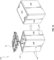
- FIG. 14 shows an assembly of a tamper-proof case 1400, in accordance with an example embodiment of the present disclosure.
- a tamper-proof case 1400 can include an internal frame 602 (as described herein) with attached panels 1206 at respective side faces 606 of the tamper-proof case 1400.
- a top insert 102 can be placed on the bottles 106. The top insert 102 can be folded prior to placing on the bottles 106, or the top insert 102 can be folded into the second configuration after being placed on the bottles 106.
- a top panel 1206 can be placed on the top face 604 of the tamper-proof case 1400 to close the bottles within the tamper-proof case 1400.
- the top insert 102 can be connected to the top panel 1206, for example by an adhesive.
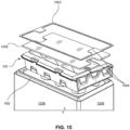
- FIG. 15 depicts a top panel 1206 that comprises security seal 1502 and is positioned above a top insert 102, according to some embodiments of the present disclosure.
- the top panel 1206 can provide enclosure of the top face 604 of the tamper-proof case 1400.
- a top insert 102 can be positioned below of top panel 1206.
- the top insert 102, top panel 1206, and security seal 1502 can each fit together based on each layer decreasing in size as the layers go from top to bottom.
- top panel 1206 has finger grooves 1504 and is positioned above top insert 102.
- security seal 1502 can be positioned around the perimeter of the top panel 1206.
- Top panel 1206 can be made of similar material to that used for construction of a side panel 1206.
- the security seal 1502 can include additional security features to ensure the case is not opened.
- the security seal 1502 can include tamper-evident tape, as described herein.
- FIG. 16 depicts a panel 1206 with an inspection release button 1602, according to some embodiments of the present disclosure.
- panels 1206 can provide enclosure of the tamper-proof case 1400 by sliding downward and onto a respective side face 606 of the frame 602.
- the inspection release button 1602 can latch onto the frame 602, providing a locking feature.
- the inspection release button 1602 can be unlocked by pressing the inspection release button 1602 when it is attached to the frame 602.
- the panel 1206 can be raised to allow inspection of the bottles 106 within the tamper-proof case 1400 without removing the bottles. For example, a user can rotate the bottles while the bottles remain secured in place to, for example, inspect the label.
- the tamper-proof case can include a frame 602 to provide support for the components within the frame 602 and provide faces for accepting panels (e.g., side panels 1206).
- the frame can be a rectangular prism, as shown in FIG. 12 .
- the frame 602 can have a first configuration that is substantially horizontal and a second configuration that has the rectangular shape, for example. The frame 602 can, therefore, be folded from the first configuration into the second configuration.
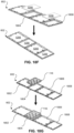
- FIGs. 17A-17D depict an embodiment with a foldable frame 602.
- FIG. 17A shows an example frame 602 for a tamper-proof case having various living hinges 1702 prior to folding the frame 602 into a final shape, according to some embodiments of the present disclosure.
- the frame 602 can contain one or more living hinges 1702.
- a living hinge 1702 can be a thin piece or portion of the frame 602 designed to allow the frame 602 to fold along the living hinge 1702.
- frame 602 can be positioned so as to allow the frame 602 to be folded into a desired position.
- frame 602 can contain one or more tabs 1704.
- tabs 1704 can provide for attachment of the panels 1206 (not shown in figure).
- tabs 1704 can be molded projections integrally formed with the frame 602.
- tabs 1704 can be projections affixed to the frame 602.
- tabs 1704 can be serrated, and as will be appreciated such serrated features of the tabs 1704 can further improve the connection at the joint between the panels 1206 and the frame 602.
- bottom insert 116 As further shown in FIG. 17A , there is provided a bottom insert 116, as previously discussed.
- bottom insert 116 prior to folding the frame 602, bottom insert 116 can be attached to the frame 602.
- bottom insert 116 can snap into place into the frame 602.
- bottom insert 116 can be press fit into a face of the frame 602.
- a flat panel instead of bottom insert 116, a flat panel can be attached to frame 602 to create a container suitable for storing or transporting, for example, cigars, jewelry, and the like.
- bottom insert 116 can be integrally formed with frame 602.
- Frame 602 also can comprise symmetric top lid frame portions, or edge attachment arms 1706a and 1706b. For example, upon folding frame 602, symmetric top lid frame portions 1706a and 1706b can connect to form the top face 604, as discussed further herein.
- FIG. 17B shows a partially assembled tamper-proof case having a frame 602 comprising various living hinges 1702 (as shown in FIG. 17A ), according to some embodiments of the present disclosure.
- the tamper-proof case can include panels 1206.
- slots can be portions of the panel 1206 that are cut out or otherwise configured to receive a portion of the frame 602.
- slots can be formed in the fashion of a mortise and tenon joint or any other suitable formation that would allow for connection to be made between the panel 1206 and the frame 602.
- the bottom of the frame 602 can include guiding tabs 1708, which can be molded projections integrally formed with the frame 602 or projections affixed to the frame 602.
- guiding tabs 1708 can provide a locating feature, indicating the location that panels 1206 are to be connected with the frame 602.
- panels 1206 can be placed within the frame 602 by inserting panels 1206 flush against the guiding tabs 1708.
- guiding tabs 1708 can penetrate the bottom slots of panels 1206, allowing attachment of panels 1206 to the bottom of the frame 602.
- frame 602 can have living hinges 1702 positioned on both sides of the bottom insert 116. As will be appreciated, such positioning of the living hinges 1702 can allow for the sides of the frame 602 to be folded upwards towards the panels 1206. Side edges of panels 1206 can connect to the frame 602 in a similar manner to the bottom edges of panels 1206 as discussed above. For example, side edges of panels 1206 can have one or more slots (not shown) and the frame 602 can have one or more tabs 1704 corresponding to the one or slots.
- the one or more tabs on the frame 602 can contact or engage the or more slots on the side edges of the panels 1206 in a manner similar to how tabs 1704 contact or engage the bottom edge of panels 1206. Accordingly, in such embodiments and as will be appreciated, panels 1206 can be attached to frame 602 both at the bottom portion and side portions without the use of nails, glue, or other adhesives. While the disclosed subject matter has been described in terms of specific positioning of living hinges 1702, it is understood that the positions described and shown herein provide only an exemplary shape for the final tamper-proof case. Accordingly, other positions are contemplated in order to achieve the desired size and shape of the tamper-proof case.
- living hinges 1702 can allow the frame 602 to be folded at the edge of each top lid frame portion 1706a and 1706b such that top lid frame portions 1706a and 1706b can be folded towards each other in order to connect and form the top surface of the frame 602.
- the top edges of side panels 1625 can have one or more slots (not shown) and the top lid frame portions 1706a and 1706b can contain can have one or more tabs 1704 corresponding to the one or slots.
- the one or more tabs 1704 on the top lid frame portions 1706a and 1706b can contact or be received by the or more slots on the top edge of the panels 1206 in a manner as previously discussed in regard to FIGS. 17A and 17B .
- top lid frame portions 1706a and 1706b can each contain male fastener or locking mechanism 1710a and a female fastener or locking mechanism 1710b.
- the male fastener 1710a can latch with the female fastener 1710b, forming the top surface of the frame 602 and locking the frame 602 in place.
- the locking feature provided by the male fastener 1710a and the female fastener 1710b allow the frame to lock without compromising the frame 602.
- the male fastener 1710a and female fastener 1710b are inaccessible once the frame 602 is fully assembled.
- the male fastener 1710a and female fastener 1710b can be snap tap fasteners, but other types of suitable fasteners can be used. According to some embodiments, once the male fastener 1710a and female fastener 1710b have closed the top lid frame portions 1706a and 1706b, the top of the frame 602 is permanently sealed. In these embodiments, a bottle within the tamper-proof case may only be removed by the methods described above, which include pulling the tabs and removing the removable portion of the elongated channel holders.
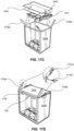
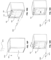
- FIGs. 18A-18S show an example frame 602 that is foldable from a horizontal, planar position to a rectangular configuration and depict a process flow for securing bottles in and removing bottles from a case, according to some embodiments of the present disclosure.
- the example frame 602 shown in FIGs. 18A-18S is similar to the frame 602 shown in FIGs. 17A-17D , but in this case the frame 602 includes a unibody top portion 1808, instead of the two top lid frame portions, or edge attachment arms 1706a and 1706b, shown in FIGs. 17A-17D .
- FIG. 18A-18S show an example frame 602 that is foldable from a horizontal, planar position to a rectangular configuration and depict a process flow for securing bottles in and removing bottles from a case, according to some embodiments of the present disclosure.
- the example frame 602 shown in FIGs. 18A-18S is similar to the frame 602 shown in FIGs. 17A-17D , but in this case the frame 602 includes a un
- the frame 602 can be a unibody frame have a substantially planar configuration comprising a plurality of living hinges 1702 that allow portions of the frame 602 to fold into a rectangular configuration.
- the frame portions can include a front portion 1802, a bottom portion 1804, a back portion 1806, and a top portion 1808.
- one or more bolts 1810 can be added to any of the portions to enable opening and closing of one of the portions. This example is shown in greater detail with reference to FIG. 18P .
- the one or more bolts 1810 can be added to corresponding opening holes 1812 in one of the frame portions.
- the bolts 1810 are added into the top portion 1808 so that the front portion 1802 can be hinged open from the top portion 1808, which is again discussed in greater detail with reference to FIG. 18P below.
- FIG. 18C is a detailed view of a bolt 1010 inserted into a corresponding opening hole 1812.
- panels 1206 for the front portion 1802 and/or back portion 1806 can be prepared to be inserted into their respective frame portion.
- Panel clips 1814 can be added into clip recesses 1815 in the panel 1206 to ensure the panel(s) 1206 is/are attached to the respective frame portion.
- the panels 1206 are inserted into the front portion 1802 and/or back portion 1806.
- additional panels 1206 can be inserted into the top portion 1808 and/or bottom portion 1804 to fully enclose the top, bottom, front, and back of the frame 602.
- a bottom insert 116 can be added to the bottom portion 1804 of the frame 602.
- two additional panels 1206 can be added to the construct to create the six sides of the final frame 602.
- the front portion 1802 and back portion 1806 can be hinged inwardly, at the living hinges 1702, to create the rectangular prism configuration, as shown in FIGs. 18I and 18J .
- FIG. 18K once the frame 602 is in the rectangular configuration, one or more bottles 106 can be loaded into the frame 602, wherein the bottom (or heel) of the bottle 106 is inserted into the bottom insert 116.
- the bottles 106 are fully loaded in the frame 602, and the top portion 1808 remains open, like a lid for the frame 602.
- a top insert 102 in FIG. 18M , can be lowered onto the top (or neck) of the bottle(s) 106.
- the elongated bottle holder(s) 104 of the top insert 102 can be slid over the neck of the bottle(s) 106 to protect the bottle(s) from lateral movement.
- FIG. 18N shows the top insert 102 fully seated on the bottles 106 within the frame 602.
- the top portion 1808 can be hinged, e.g., along a living hinge 1702, to close the frame 602, as shown in FIG. 18O .
- the frame 602 is enclosed, thereby creating the case as described herein.
- the bolts 1810 can latch onto the material of the front portion 1802 of the frame 602 to secure the case into its closed configuration.
- the opening holes 1812 described above can provide access to the bolts 1810, such that they can be bent slightly to disengage the bolts 1810 from the front portion 1802 of the frame 602. This can be completed, for example, by inserting one or more pins 1816 into an opening hole 1812 to engage the bolts 1810, bend the bolts 1810, and release the front portion 1802 of the frame 602. If more than one bolt 1810 (and corresponding opening hole 1812) is present, then each bolt 1810 can be bent simultaneously with more than one pin 1816 to open the front portion 1802 of the frame 602.
- FIG. 18Q once the bolts 1810 are bent slightly, the front portion 1802 of the frame 602 can be opened to reveal the bottles 106 stored within the frame 602. At this point, a tab 110 on the top insert 102, as described above, can be pulled to create an opening 702 in an elongated bottle holders 104 from which a bottle 106 can be removed. In FIG. 18R , the tab 110 is removed to create the opening 702, and in FIG. 18S , the bottle 106 is removed from the top insert 102.
- one aspect of the present discourse is the ability to remove a single bottle 106 without tampering with adjacent bottles stored in the case.
- the front portion 1802 of the frame 602 can be hinged back into place to close the frame 602. Since the bolts 1810 remain in place, the case can be resealed for storage of the remaining bottles 106.
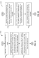
- FIG. 19 is a flow diagram of an example method 1900 for securing one or more bottles, according to some embodiments of the present disclosure.
- Method 1900 can be performed, for example, with the example tamper-proof cases described herein.
- Method 1900 can begin at step 1905, which includes providing a top insert of a bottle case.
- the top insert includes a bottom level having a plurality of elongated bottle holders.
- Each of the bottle holders include an inner channel having a first end and a second end, the first end being configured to accept a neck of a bottle.
- the bottle holders include a perimeter surface surrounding the inner channel.
- the bottle holders include a tab connected to a removable portion the perimeter surface. The removable portion is configured to be removed upon the pulling of a tab.
- the top insert also includes a top level that has a plurality of securing platforms configured to contact a top of the bottle.
- the top level is configured to fold from a first position to a second position, wherein the first position is substantially horizontal to the bottom level, and wherein the second position is proximate the second end of the inner channels.
- method 1900 includes inserting the neck of the bottle into the first end of the inner channel of at least one elongated bottle holder.
- the top level of the top insert is folded from its first position to its second position. In the second position, at least one securing platform can contact the top of the bottle to secure the bottle.
- Method 1900 can end after step 1915.
- additional steps can be performed according to the examples described herein, including but not limiting to securing the bottles within a bottom insert.
- FIG. 20 is a flow diagram of an example method 2000 of removing a bottle from a tamper-proof case, according to some embodiments of the present disclosure.
- the method steps shown in method 2000 can be used, for example, to remove a bottle that was secured using the steps shown in method 1900 of FIG. 19 .
- Method 2000 can begin at step 2005, which includes receiving a case.
- the case can include a top insert having an elongated bottle holder. A neck of a bottle can be held and secured by the elongated bottle holder.
- method 2000 can include pulling a tab on the elongated bottle holder to remove a removable portion of the elongated bottle holder. Removal of the portion can create an opening in the elongated bottle holder so as to enable removal of the bottle.
- method 2000 can include pulling the bottle neck from the opening created by pulling the tab. Method 2000 can end after step 2015. In other examples, additional steps can be performed according to the examples described herein.
Landscapes
- Engineering & Computer Science (AREA)
- Mechanical Engineering (AREA)
- Details Of Rigid Or Semi-Rigid Containers (AREA)
- Packages (AREA)
Claims (13)
- Manipulationssicherer Flaschenkasten, umfassend:einen Rahmen (602) mit einer Oberseite (604), einer Unterseite (1202) und vier im Wesentlichen horizontalen Seitenflächen (606);einen oberen Einsatz (102), der so konfiguriert ist, dass der obere Einsatz von einer ersten Konfiguration in eine zweite Konfiguration gefaltet werden kann, wobei die erste Konfiguration eine im Wesentlichen horizontale Konfiguration ist und die zweite Konfiguration konfiguriert ist, um in der Nähe der oberen Fläche angeordnet zu sein, wobei der obere Einsatz (102) umfasst:eine Mehrzahl von langgestreckten Flaschenhaltern (104), wobei jeder langgestreckte Flaschenhalter (104) umfasst:einen inneren Kanal (304), der konfiguriert ist, um einen Flaschenhals aufzunehmen;eine Umfangsfläche (108), die den inneren Kanal (304) umgibt; undeine Lasche (110), die mit einem entfernbaren Abschnitt (308) der Umfangsfläche (108) verbunden ist, wobei der entfernbare Abschnitt (308) der Umfangsfläche konfiguriert ist, um bei einem Ziehen an der Lasche entfernt zu werden; undeinen unteren Einsatz (116), der in der Nähe der Unterseite angeordnet ist, wobei der untere Einsatz eine Mehrzahl von Bechern (118) umfasst, die konfiguriert sind, um einen Flaschenboden aufzunehmen, wobei:der innere Kanal (304) jedes langgestreckten Flaschenhalters (104) der Mehrzahl von langgestreckten Flaschenhaltern ein erstes Ende und ein zweites Ende umfasst;das erste Ende konfiguriert ist, um den Flaschenhals aufzunehmen;wobei der manipulationssichere Flaschenkasten dadurch gekennzeichnet ist, dass:der obere Einsatz (102) ferner einen Flansch umfasst, der eine Mehrzahl von Sicherungsplattformen (112) umfasst, wobei jede Sicherungsplattform (112) konfiguriert ist, um einen oberen Teil einer Flasche zu berühren;die Mehrzahl von Sicherungsplattformen (112), wenn sie sich in der ersten Konfiguration befinden, im Wesentlichen horizontal zu der Mehrzahl von langgestreckten Flaschenhaltern (104) sind; unddie Mehrzahl von Sicherungsplattformen (112) sich in der zweiten Konfiguration in der Nähe des zweiten Endes der Mehrzahl von langgestreckten Flaschenhaltern (104) befinden.
- Manipulationssicherer Flaschenkasten nach Anspruch 1, bei dem das zweite Ende des inneren Kanals (304) jedes langgestreckten Flaschenhalters (104) eine Sicherungsplattform (112) umfasst, die konfiguriert ist, um einen oberen Teil der Flasche zu berühren.
- Manipulationssicherer Flaschenkasten nach Anspruch 1, der ferner umfasst:eine obere Platte (1206);eine Bodenplatte (1206); undvier Seitenplatten (1206);wobei die Oberseite (604) die obere Platte (1206) aufnimmt;die Unterseite (1202) die Bodenplatte (1206) aufnimmt;jede der vier im Wesentlichen horizontalen Seitenflächen (606) eine Seitenplatte (1206) aufnimmt.
- Manipulationssicherer Flaschenkasten nach Anspruch 3, bei dem mindestens eine der vier Seitenplatten transparent ist.
- Manipulationssicherer Flaschenkasten nach Anspruch 1, bei dem der Rahmen (602) eine Mehrzahl von Filmscharnieren (1702) umfasst, so dass der Rahmen von einer ersten im Wesentlichen ebenen Konfiguration in eine zweite im Wesentlichen rechteckige Prismenkonfiguration faltbar ist.
- Verfahren zum Sichern von Flaschen (106), umfassend:Bereitstellen (1905) eines oberen Einsatzes (102), umfassend:eine untere Ebene, umfassend eine Mehrzahl von langgestreckten Flaschenhaltern (104), wobei jeder langgestreckte Flaschenhalter (104) umfasst:einen inneren Kanal (304) mit einem ersten Ende und einem zweiten Ende, wobei das erste Ende konfiguriert ist, um einen Flaschenhals aufzunehmen;eine Umfangsfläche (108), die den inneren Kanal (304) umgibt; und eine Lasche (110), die mit einem entfernbaren Abschnitt (308) der Umfangsfläche (108) verbunden ist, wobei der entfernbare Abschnitt (308) der Umfangsfläche konfiguriert ist, um bei einem Ziehen an der Lasche entfernt zu werden; undeine obere Ebene, umfassend eine Mehrzahl von Sicherungsplattformen (112), die konfiguriert sind, um einen oberen Teil einer Flasche zu berühren, wobei die obere Ebene konfiguriert ist, um von einer ersten Position in eine zweite Position gefaltet zu werden, wobei die erste Position im Wesentlichen horizontal zur unteren Ebene ist und wobei die zweite Position in der Nähe des zweiten Endes der inneren Kanäle ist;Einführen (1910) eines Halses der Flasche in das erste Ende des inneren Kanals mindestens eines langgestreckten Flaschenhalters (104); undFalten (1915) der oberen Ebene von der ersten Position in die zweite Position, so dass mindestens eine der Mehrzahl von Sicherungsplattformen (112) den oberen Teil der Flasche berührt.
- Verfahren zum Sichern von Flaschen nach Anspruch 6, das ferner umfasst:Bereitstellen eines unteren Einsatzes (116), der eine Mehrzahl von Bechern (118) umfasst, die konfiguriert sind, um einen Flaschenboden aufzunehmen; undEinsetzen des Bodens der Flasche in mindestens einen Becher der Mehrzahl von Bechern (118).
- Verfahren zum Sichern von Flaschen nach Anspruch 7, das ferner umfasst:Bereitstellen eines Rahmens (602) mit einer Oberseite (604), einer Unterseite (1202) und vier im Wesentlichen horizontalen Seitenflächen (606);Platzieren des unteren Einsatzes (116) in der Nähe der Unterseite (1202); undPlatzieren des oberen Einsatzes (102) in der Nähe der Oberseite (604).
- Verfahren zum Sichern von Flaschen nach Anspruch 8, das ferner umfasst:Anordnen einer oberen Platte (1206) in der Nähe der Oberseite (604); undBefestigen der Flasche, des oberen Einsatzes (102) und des unteren Einsatzes (116) innerhalb des Rahmens (602).
- Verfahren zum Sichern und Entfernen von Flaschen, wobei das Verfahren das Verfahren nach Anspruch 9 umfasst und ferner umfasst:Ziehen (2010) an der Lasche (110);Entfernen des entfernbaren Abschnitts (308) der Umfangsfläche, um eine Öffnung in der Umfangsfläche zu schaffen;Herausziehen (2015) des Halses der Flasche aus der Öffnung in der Umfangsfläche; undEntfernen der Flasche aus dem Rahmen (602).
- Manipulationssicherer Flaschenkasten nach Anspruch 1 oder Verfahren zum Sichern von Flaschen nach Anspruch 6,
wobei die Umfangsfläche eine Kegelstumpfform aufweist und wobei die Lasche (110) konfiguriert ist, um den entfernbaren Teil der Kegelstumpfform zu entfernen. - Manipulationssicherer Flaschenkasten nach Anspruch 1 oder Verfahren zum Sichern von Flaschen nach Anspruch 6,
wobei der entfernbare Abschnitt der Umfangsfläche eben ist. - Manipulationssicherer Flaschenkasten nach Anspruch 1 oder Verfahren zum Sichern von Flaschen nach Anspruch 6,
wobei mindestens ein Abschnitt der Umfangsfläche die Form eines Kegelstumpfes aufweist und wobei der entfernbare Abschnitt der Umfangsfläche eben ist.
Applications Claiming Priority (2)
| Application Number | Priority Date | Filing Date | Title |
|---|---|---|---|
| CN201920961637.5U CN210708457U (zh) | 2019-06-25 | 2019-06-25 | 防窃启瓶箱及防窃启插入物 |
| PCT/US2020/039385 WO2020263999A1 (en) | 2019-06-25 | 2020-06-24 | Tamper-proof bottle case and methods thereof |
Publications (3)
| Publication Number | Publication Date |
|---|---|
| EP3990366A1 EP3990366A1 (de) | 2022-05-04 |
| EP3990366A4 EP3990366A4 (de) | 2023-11-01 |
| EP3990366B1 true EP3990366B1 (de) | 2025-03-19 |
Family
ID=70927731
Family Applications (1)
| Application Number | Title | Priority Date | Filing Date |
|---|---|---|---|
| EP20832022.6A Active EP3990366B1 (de) | 2019-06-25 | 2020-06-24 | Flaschenkasten mit originalitätsverschluss und verfahren zur sicherung von flaschen |
Country Status (3)
| Country | Link |
|---|---|
| EP (1) | EP3990366B1 (de) |
| CN (1) | CN210708457U (de) |
| WO (1) | WO2020263999A1 (de) |
Citations (1)
| Publication number | Priority date | Publication date | Assignee | Title |
|---|---|---|---|---|
| US20030192787A1 (en) * | 2002-04-12 | 2003-10-16 | Jay Packaging Group, Inc. | Multiple pack bottle holder |
Family Cites Families (12)
| Publication number | Priority date | Publication date | Assignee | Title |
|---|---|---|---|---|
| US2287731A (en) * | 1941-10-20 | 1942-06-23 | Charles M Franks | Combined bottle lifter and carrier |
| NO834013L (no) | 1982-11-04 | 1984-05-07 | Patent Dev International Ltd | Baereholder |
| US4911300A (en) * | 1987-07-27 | 1990-03-27 | Ralph Colonna | Container packaging system |
| US5407065A (en) * | 1994-03-02 | 1995-04-18 | Riverwood International Corporation | Bottle neck carrier |
| US5476170A (en) * | 1994-06-13 | 1995-12-19 | The Mead Corporation | Bottle carrier having improved gripping means |
| BR9709087A (pt) * | 1996-05-16 | 2000-01-11 | Gregory W Gale | Combinação de uma embalagem e uma pluralidade de recipientes, modelos de embalagem, inserção e método para a fabricação de uma embalagem contendo uma pluralidade de meia inserções. |
| US6325210B1 (en) * | 1999-02-04 | 2001-12-04 | Douglass C. Henry, Jr. | Wine bottle package |
| US6213297B1 (en) * | 1999-08-30 | 2001-04-10 | Regale, Corporation | Packaging for bottles and bottle neck shroud for use therewith |
| US7252196B1 (en) * | 2000-11-10 | 2007-08-07 | Rehrig Pacific Company | Crate for bottles and other containers |
| US7789239B2 (en) * | 2006-12-11 | 2010-09-07 | Don Juliano | Insert trays for packages, packages including such trays, and methods for packaging articles of manufacture |
| US10479597B2 (en) * | 2017-06-07 | 2019-11-19 | Citadel Casing Ltd | Tamper-proof case systems and methods |
| GB201711894D0 (en) * | 2017-07-24 | 2017-09-06 | Oakbridge Invest Ltd | Bottle packaging |
-
2019
- 2019-06-25 CN CN201920961637.5U patent/CN210708457U/zh active Active
-
2020
- 2020-06-24 EP EP20832022.6A patent/EP3990366B1/de active Active
- 2020-06-24 WO PCT/US2020/039385 patent/WO2020263999A1/en not_active Ceased
Patent Citations (1)
| Publication number | Priority date | Publication date | Assignee | Title |
|---|---|---|---|---|
| US20030192787A1 (en) * | 2002-04-12 | 2003-10-16 | Jay Packaging Group, Inc. | Multiple pack bottle holder |
Also Published As
| Publication number | Publication date |
|---|---|
| EP3990366A4 (de) | 2023-11-01 |
| WO2020263999A1 (en) | 2020-12-30 |
| EP3990366A1 (de) | 2022-05-04 |
| CN210708457U (zh) | 2020-06-09 |
Similar Documents
| Publication | Publication Date | Title |
|---|---|---|
| US20090090712A1 (en) | Dip packaging system | |
| EP1530543B1 (de) | Produktbehälter mit verriegelbarer endkappe | |
| US11492173B2 (en) | Folding case and methods thereof | |
| US20060027481A1 (en) | Multi-functional compact with storage receptacles | |
| US20100102074A1 (en) | Tamper evident container with frangible hinge | |
| US20120279969A1 (en) | Overcap for a container | |
| US10479597B2 (en) | Tamper-proof case systems and methods | |
| US11472593B1 (en) | Auto-locking and tamper evident container | |
| US5244093A (en) | Sleeve package with supporting engagement | |
| US10457459B2 (en) | Package | |
| US20030234252A1 (en) | Secure packaging and mailing container | |
| US11866236B2 (en) | Folding tamper-proof case with reinforcing inserts | |
| CN210213173U (zh) | 显窃启瓶箱 | |
| WO2021244012A1 (en) | Folding tamper-proof case with reinforcing inserts | |
| EP3990366A1 (de) | Flaschenbox mit originalitätsverschluss und verfahren dafür | |
| US20070163914A1 (en) | Package closure | |
| EP4019419B1 (de) | Gehäuseanordnung | |
| EP3919403B1 (de) | Faltbarer manipulationssicherer koffer mit verstärkungseinlagen | |
| JP4979466B2 (ja) | ボトル体への容器取付用個装箱 | |
| WO2021000243A1 (en) | Tamper-proof bottle case | |
| JP4707135B2 (ja) | 物品収容箱 | |
| WO2021097789A1 (en) | Bottle cases with tamper-proof security and methods thereof | |
| CN210556287U (zh) | 显窃启箱 | |
| US20090000966A1 (en) | Package with Primary and Ancillary Item Compartments | |
| JP2017210271A (ja) | 物品包装箱 |
Legal Events
| Date | Code | Title | Description |
|---|---|---|---|
| STAA | Information on the status of an ep patent application or granted ep patent |
Free format text: STATUS: THE INTERNATIONAL PUBLICATION HAS BEEN MADE |
|
| PUAI | Public reference made under article 153(3) epc to a published international application that has entered the european phase |
Free format text: ORIGINAL CODE: 0009012 |
|
| STAA | Information on the status of an ep patent application or granted ep patent |
Free format text: STATUS: REQUEST FOR EXAMINATION WAS MADE |
|
| 17P | Request for examination filed |
Effective date: 20210331 |
|
| AK | Designated contracting states |
Kind code of ref document: A1 Designated state(s): AL AT BE BG CH CY CZ DE DK EE ES FI FR GB GR HR HU IE IS IT LI LT LU LV MC MK MT NL NO PL PT RO RS SE SI SK SM TR |
|
| DAV | Request for validation of the european patent (deleted) | ||
| DAX | Request for extension of the european patent (deleted) | ||
| RIC1 | Information provided on ipc code assigned before grant |
Ipc: B65D 55/02 20060101ALI20230620BHEP Ipc: B65D 71/50 20060101ALI20230620BHEP Ipc: B65D 81/02 20060101ALI20230620BHEP Ipc: B65D 25/54 20060101ALI20230620BHEP Ipc: B65D 25/10 20060101ALI20230620BHEP Ipc: B65D 43/16 20060101ALI20230620BHEP Ipc: B65D 81/05 20060101ALI20230620BHEP Ipc: B65D 85/30 20060101AFI20230620BHEP |
|
| A4 | Supplementary search report drawn up and despatched |
Effective date: 20230928 |
|
| RIC1 | Information provided on ipc code assigned before grant |
Ipc: B65D 55/02 20060101ALI20230922BHEP Ipc: B65D 71/50 20060101ALI20230922BHEP Ipc: B65D 81/02 20060101ALI20230922BHEP Ipc: B65D 25/54 20060101ALI20230922BHEP Ipc: B65D 25/10 20060101ALI20230922BHEP Ipc: B65D 43/16 20060101ALI20230922BHEP Ipc: B65D 81/05 20060101ALI20230922BHEP Ipc: B65D 85/30 20060101AFI20230922BHEP |
|
| GRAP | Despatch of communication of intention to grant a patent |
Free format text: ORIGINAL CODE: EPIDOSNIGR1 |
|
| STAA | Information on the status of an ep patent application or granted ep patent |
Free format text: STATUS: GRANT OF PATENT IS INTENDED |
|
| INTG | Intention to grant announced |
Effective date: 20241007 |
|
| GRAS | Grant fee paid |
Free format text: ORIGINAL CODE: EPIDOSNIGR3 |
|
| GRAA | (expected) grant |
Free format text: ORIGINAL CODE: 0009210 |
|
| STAA | Information on the status of an ep patent application or granted ep patent |
Free format text: STATUS: THE PATENT HAS BEEN GRANTED |
|
| AK | Designated contracting states |
Kind code of ref document: B1 Designated state(s): AL AT BE BG CH CY CZ DE DK EE ES FI FR GB GR HR HU IE IS IT LI LT LU LV MC MK MT NL NO PL PT RO RS SE SI SK SM TR |
|
| REG | Reference to a national code |
Ref country code: GB Ref legal event code: FG4D |
|
| REG | Reference to a national code |
Ref country code: CH Ref legal event code: EP |
|
| REG | Reference to a national code |
Ref country code: IE Ref legal event code: FG4D |
|
| REG | Reference to a national code |
Ref country code: DE Ref legal event code: R096 Ref document number: 602020048056 Country of ref document: DE |
|
| PG25 | Lapsed in a contracting state [announced via postgrant information from national office to epo] |
Ref country code: RS Free format text: LAPSE BECAUSE OF FAILURE TO SUBMIT A TRANSLATION OF THE DESCRIPTION OR TO PAY THE FEE WITHIN THE PRESCRIBED TIME-LIMIT Effective date: 20250619 |
|
| PG25 | Lapsed in a contracting state [announced via postgrant information from national office to epo] |
Ref country code: FI Free format text: LAPSE BECAUSE OF FAILURE TO SUBMIT A TRANSLATION OF THE DESCRIPTION OR TO PAY THE FEE WITHIN THE PRESCRIBED TIME-LIMIT Effective date: 20250319 |
|
| REG | Reference to a national code |
Ref country code: LT Ref legal event code: MG9D |
|
| PG25 | Lapsed in a contracting state [announced via postgrant information from national office to epo] |
Ref country code: NO Free format text: LAPSE BECAUSE OF FAILURE TO SUBMIT A TRANSLATION OF THE DESCRIPTION OR TO PAY THE FEE WITHIN THE PRESCRIBED TIME-LIMIT Effective date: 20250619 |
|
| PG25 | Lapsed in a contracting state [announced via postgrant information from national office to epo] |
Ref country code: HR Free format text: LAPSE BECAUSE OF FAILURE TO SUBMIT A TRANSLATION OF THE DESCRIPTION OR TO PAY THE FEE WITHIN THE PRESCRIBED TIME-LIMIT Effective date: 20250319 |
|
| PG25 | Lapsed in a contracting state [announced via postgrant information from national office to epo] |
Ref country code: LV Free format text: LAPSE BECAUSE OF FAILURE TO SUBMIT A TRANSLATION OF THE DESCRIPTION OR TO PAY THE FEE WITHIN THE PRESCRIBED TIME-LIMIT Effective date: 20250319 |
|
| PG25 | Lapsed in a contracting state [announced via postgrant information from national office to epo] |
Ref country code: GR Free format text: LAPSE BECAUSE OF FAILURE TO SUBMIT A TRANSLATION OF THE DESCRIPTION OR TO PAY THE FEE WITHIN THE PRESCRIBED TIME-LIMIT Effective date: 20250620 Ref country code: BG Free format text: LAPSE BECAUSE OF FAILURE TO SUBMIT A TRANSLATION OF THE DESCRIPTION OR TO PAY THE FEE WITHIN THE PRESCRIBED TIME-LIMIT Effective date: 20250319 |
|
| REG | Reference to a national code |
Ref country code: NL Ref legal event code: MP Effective date: 20250319 |
|
| REG | Reference to a national code |
Ref country code: AT Ref legal event code: MK05 Ref document number: 1776815 Country of ref document: AT Kind code of ref document: T Effective date: 20250319 |
|
| PG25 | Lapsed in a contracting state [announced via postgrant information from national office to epo] |
Ref country code: NL Free format text: LAPSE BECAUSE OF FAILURE TO SUBMIT A TRANSLATION OF THE DESCRIPTION OR TO PAY THE FEE WITHIN THE PRESCRIBED TIME-LIMIT Effective date: 20250319 |
|
| PG25 | Lapsed in a contracting state [announced via postgrant information from national office to epo] |
Ref country code: SE Free format text: LAPSE BECAUSE OF FAILURE TO SUBMIT A TRANSLATION OF THE DESCRIPTION OR TO PAY THE FEE WITHIN THE PRESCRIBED TIME-LIMIT Effective date: 20250319 |
|
| PG25 | Lapsed in a contracting state [announced via postgrant information from national office to epo] |
Ref country code: SM Free format text: LAPSE BECAUSE OF FAILURE TO SUBMIT A TRANSLATION OF THE DESCRIPTION OR TO PAY THE FEE WITHIN THE PRESCRIBED TIME-LIMIT Effective date: 20250319 |
|
| PG25 | Lapsed in a contracting state [announced via postgrant information from national office to epo] |
Ref country code: PT Free format text: LAPSE BECAUSE OF FAILURE TO SUBMIT A TRANSLATION OF THE DESCRIPTION OR TO PAY THE FEE WITHIN THE PRESCRIBED TIME-LIMIT Effective date: 20250721 Ref country code: ES Free format text: LAPSE BECAUSE OF FAILURE TO SUBMIT A TRANSLATION OF THE DESCRIPTION OR TO PAY THE FEE WITHIN THE PRESCRIBED TIME-LIMIT Effective date: 20250319 |
|
| PG25 | Lapsed in a contracting state [announced via postgrant information from national office to epo] |
Ref country code: PL Free format text: LAPSE BECAUSE OF FAILURE TO SUBMIT A TRANSLATION OF THE DESCRIPTION OR TO PAY THE FEE WITHIN THE PRESCRIBED TIME-LIMIT Effective date: 20250319 Ref country code: IT Free format text: LAPSE BECAUSE OF FAILURE TO SUBMIT A TRANSLATION OF THE DESCRIPTION OR TO PAY THE FEE WITHIN THE PRESCRIBED TIME-LIMIT Effective date: 20250319 |
|
| PGFP | Annual fee paid to national office [announced via postgrant information from national office to epo] |
Ref country code: GB Payment date: 20250822 Year of fee payment: 6 |
|
| PG25 | Lapsed in a contracting state [announced via postgrant information from national office to epo] |
Ref country code: AT Free format text: LAPSE BECAUSE OF FAILURE TO SUBMIT A TRANSLATION OF THE DESCRIPTION OR TO PAY THE FEE WITHIN THE PRESCRIBED TIME-LIMIT Effective date: 20250319 |
|
| PGFP | Annual fee paid to national office [announced via postgrant information from national office to epo] |
Ref country code: FR Payment date: 20250822 Year of fee payment: 6 |
|
| PG25 | Lapsed in a contracting state [announced via postgrant information from national office to epo] |
Ref country code: CZ Free format text: LAPSE BECAUSE OF FAILURE TO SUBMIT A TRANSLATION OF THE DESCRIPTION OR TO PAY THE FEE WITHIN THE PRESCRIBED TIME-LIMIT Effective date: 20250319 Ref country code: EE Free format text: LAPSE BECAUSE OF FAILURE TO SUBMIT A TRANSLATION OF THE DESCRIPTION OR TO PAY THE FEE WITHIN THE PRESCRIBED TIME-LIMIT Effective date: 20250319 |
|
| PG25 | Lapsed in a contracting state [announced via postgrant information from national office to epo] |
Ref country code: RO Free format text: LAPSE BECAUSE OF FAILURE TO SUBMIT A TRANSLATION OF THE DESCRIPTION OR TO PAY THE FEE WITHIN THE PRESCRIBED TIME-LIMIT Effective date: 20250319 |
|
| PG25 | Lapsed in a contracting state [announced via postgrant information from national office to epo] |
Ref country code: SK Free format text: LAPSE BECAUSE OF FAILURE TO SUBMIT A TRANSLATION OF THE DESCRIPTION OR TO PAY THE FEE WITHIN THE PRESCRIBED TIME-LIMIT Effective date: 20250319 |
|
| PG25 | Lapsed in a contracting state [announced via postgrant information from national office to epo] |
Ref country code: IS Free format text: LAPSE BECAUSE OF FAILURE TO SUBMIT A TRANSLATION OF THE DESCRIPTION OR TO PAY THE FEE WITHIN THE PRESCRIBED TIME-LIMIT Effective date: 20250719 |
|
| REG | Reference to a national code |
Ref country code: DE Ref legal event code: R097 Ref document number: 602020048056 Country of ref document: DE |
|
| REG | Reference to a national code |
Ref country code: DE Ref legal event code: R119 Ref document number: 602020048056 Country of ref document: DE |
|
| PG25 | Lapsed in a contracting state [announced via postgrant information from national office to epo] |
Ref country code: DK Free format text: LAPSE BECAUSE OF FAILURE TO SUBMIT A TRANSLATION OF THE DESCRIPTION OR TO PAY THE FEE WITHIN THE PRESCRIBED TIME-LIMIT Effective date: 20250319 |
|
| PLBE | No opposition filed within time limit |
Free format text: ORIGINAL CODE: 0009261 |
|
| STAA | Information on the status of an ep patent application or granted ep patent |
Free format text: STATUS: NO OPPOSITION FILED WITHIN TIME LIMIT |
|
| REG | Reference to a national code |
Ref country code: CH Ref legal event code: H13 Free format text: ST27 STATUS EVENT CODE: U-0-0-H10-H13 (AS PROVIDED BY THE NATIONAL OFFICE) Effective date: 20260127 |
|
| REG | Reference to a national code |
Ref country code: CH Ref legal event code: L10 Free format text: ST27 STATUS EVENT CODE: U-0-0-L10-L00 (AS PROVIDED BY THE NATIONAL OFFICE) Effective date: 20260128 |
|
| PG25 | Lapsed in a contracting state [announced via postgrant information from national office to epo] |
Ref country code: MC Free format text: LAPSE BECAUSE OF FAILURE TO SUBMIT A TRANSLATION OF THE DESCRIPTION OR TO PAY THE FEE WITHIN THE PRESCRIBED TIME-LIMIT Effective date: 20250319 |
|
| PG25 | Lapsed in a contracting state [announced via postgrant information from national office to epo] |
Ref country code: LU Free format text: LAPSE BECAUSE OF NON-PAYMENT OF DUE FEES Effective date: 20250624 |
|
| 26N | No opposition filed |
Effective date: 20251222 |
|
| REG | Reference to a national code |
Ref country code: BE Ref legal event code: MM Effective date: 20250630 |
|
| PG25 | Lapsed in a contracting state [announced via postgrant information from national office to epo] |
Ref country code: IE Free format text: LAPSE BECAUSE OF NON-PAYMENT OF DUE FEES Effective date: 20250624 Ref country code: DE Free format text: LAPSE BECAUSE OF NON-PAYMENT OF DUE FEES Effective date: 20260101 |
|
| PG25 | Lapsed in a contracting state [announced via postgrant information from national office to epo] |
Ref country code: BE Free format text: LAPSE BECAUSE OF NON-PAYMENT OF DUE FEES Effective date: 20250630 |
|
| PG25 | Lapsed in a contracting state [announced via postgrant information from national office to epo] |
Ref country code: CH Free format text: LAPSE BECAUSE OF NON-PAYMENT OF DUE FEES Effective date: 20250630 |