EP3990375B1 - Dispositif et procédé de transport de contenants - Google Patents
Dispositif et procédé de transport de contenants Download PDFInfo
- Publication number
- EP3990375B1 EP3990375B1 EP20734512.5A EP20734512A EP3990375B1 EP 3990375 B1 EP3990375 B1 EP 3990375B1 EP 20734512 A EP20734512 A EP 20734512A EP 3990375 B1 EP3990375 B1 EP 3990375B1
- Authority
- EP
- European Patent Office
- Prior art keywords
- transport
- transport path
- üka2
- section
- curve
- Prior art date
- Legal status (The legal status is an assumption and is not a legal conclusion. Google has not performed a legal analysis and makes no representation as to the accuracy of the status listed.)
- Active
Links
Images


Classifications
-
- B—PERFORMING OPERATIONS; TRANSPORTING
- B65—CONVEYING; PACKING; STORING; HANDLING THIN OR FILAMENTARY MATERIAL
- B65G—TRANSPORT OR STORAGE DEVICES, e.g. CONVEYORS FOR LOADING OR TIPPING, SHOP CONVEYOR SYSTEMS OR PNEUMATIC TUBE CONVEYORS
- B65G35/00—Mechanical conveyors not otherwise provided for
-
- B—PERFORMING OPERATIONS; TRANSPORTING
- B65—CONVEYING; PACKING; STORING; HANDLING THIN OR FILAMENTARY MATERIAL
- B65G—TRANSPORT OR STORAGE DEVICES, e.g. CONVEYORS FOR LOADING OR TIPPING, SHOP CONVEYOR SYSTEMS OR PNEUMATIC TUBE CONVEYORS
- B65G47/00—Article or material-handling devices associated with conveyors; Methods employing such devices
- B65G47/74—Feeding, transfer, or discharging devices of particular kinds or types
- B65G47/84—Star-shaped wheels or devices having endless travelling belts or chains, the wheels or devices being equipped with article-engaging elements
- B65G47/846—Star-shaped wheels or wheels equipped with article-engaging elements
-
- B—PERFORMING OPERATIONS; TRANSPORTING
- B65—CONVEYING; PACKING; STORING; HANDLING THIN OR FILAMENTARY MATERIAL
- B65G—TRANSPORT OR STORAGE DEVICES, e.g. CONVEYORS FOR LOADING OR TIPPING, SHOP CONVEYOR SYSTEMS OR PNEUMATIC TUBE CONVEYORS
- B65G21/00—Supporting or protective framework or housings for endless load-carriers or traction elements of belt or chain conveyors
- B65G21/20—Means incorporated in, or attached to, framework or housings for guiding load-carriers, traction elements or loads supported on moving surfaces
- B65G21/2045—Mechanical means for guiding or retaining the load on the load-carrying surface
- B65G21/2063—Mechanical means for guiding or retaining the load on the load-carrying surface comprising elements not movable in the direction of load-transport
- B65G21/2072—Laterial guidance means
-
- B—PERFORMING OPERATIONS; TRANSPORTING
- B65—CONVEYING; PACKING; STORING; HANDLING THIN OR FILAMENTARY MATERIAL
- B65G—TRANSPORT OR STORAGE DEVICES, e.g. CONVEYORS FOR LOADING OR TIPPING, SHOP CONVEYOR SYSTEMS OR PNEUMATIC TUBE CONVEYORS
- B65G43/00—Control devices, e.g. for safety, warning or fault-correcting
-
- B—PERFORMING OPERATIONS; TRANSPORTING
- B65—CONVEYING; PACKING; STORING; HANDLING THIN OR FILAMENTARY MATERIAL
- B65G—TRANSPORT OR STORAGE DEVICES, e.g. CONVEYORS FOR LOADING OR TIPPING, SHOP CONVEYOR SYSTEMS OR PNEUMATIC TUBE CONVEYORS
- B65G43/00—Control devices, e.g. for safety, warning or fault-correcting
- B65G43/08—Control devices operated by article or material being fed, conveyed or discharged
-
- B—PERFORMING OPERATIONS; TRANSPORTING
- B67—OPENING, CLOSING OR CLEANING BOTTLES, JARS OR SIMILAR CONTAINERS; LIQUID HANDLING
- B67C—CLEANING, FILLING WITH LIQUIDS OR SEMILIQUIDS, OR EMPTYING, OF BOTTLES, JARS, CANS, CASKS, BARRELS, OR SIMILAR CONTAINERS, NOT OTHERWISE PROVIDED FOR; FUNNELS
- B67C7/00—Concurrent cleaning, filling, and closing of bottles; Processes or devices for at least two of these operations
- B67C7/0006—Conveying; Synchronising
- B67C7/004—Conveying; Synchronising the containers travelling along a circular path
- B67C7/0046—Infeed and outfeed devices
-
- B—PERFORMING OPERATIONS; TRANSPORTING
- B65—CONVEYING; PACKING; STORING; HANDLING THIN OR FILAMENTARY MATERIAL
- B65G—TRANSPORT OR STORAGE DEVICES, e.g. CONVEYORS FOR LOADING OR TIPPING, SHOP CONVEYOR SYSTEMS OR PNEUMATIC TUBE CONVEYORS
- B65G2201/00—Indexing codes relating to handling devices, e.g. conveyors, characterised by the type of product or load being conveyed or handled
- B65G2201/02—Articles
- B65G2201/0235—Containers
-
- B—PERFORMING OPERATIONS; TRANSPORTING
- B65—CONVEYING; PACKING; STORING; HANDLING THIN OR FILAMENTARY MATERIAL
- B65G—TRANSPORT OR STORAGE DEVICES, e.g. CONVEYORS FOR LOADING OR TIPPING, SHOP CONVEYOR SYSTEMS OR PNEUMATIC TUBE CONVEYORS
- B65G2203/00—Indexing code relating to control or detection of the articles or the load carriers during conveying
- B65G2203/02—Control or detection
-
- B—PERFORMING OPERATIONS; TRANSPORTING
- B65—CONVEYING; PACKING; STORING; HANDLING THIN OR FILAMENTARY MATERIAL
- B65G—TRANSPORT OR STORAGE DEVICES, e.g. CONVEYORS FOR LOADING OR TIPPING, SHOP CONVEYOR SYSTEMS OR PNEUMATIC TUBE CONVEYORS
- B65G2203/00—Indexing code relating to control or detection of the articles or the load carriers during conveying
- B65G2203/02—Control or detection
- B65G2203/0208—Control or detection relating to the transported articles
-
- B—PERFORMING OPERATIONS; TRANSPORTING
- B65—CONVEYING; PACKING; STORING; HANDLING THIN OR FILAMENTARY MATERIAL
- B65G—TRANSPORT OR STORAGE DEVICES, e.g. CONVEYORS FOR LOADING OR TIPPING, SHOP CONVEYOR SYSTEMS OR PNEUMATIC TUBE CONVEYORS
- B65G2203/00—Indexing code relating to control or detection of the articles or the load carriers during conveying
- B65G2203/04—Detection means
- B65G2203/042—Sensors
Definitions
- the invention relates to a device and a method for transporting containers, and in particular for transporting containers in a transfer area between two transport elements adjacent in the transport direction.
- Devices for transporting containers are well known, particularly in the beverage industry. Such devices can have several transport elements, each driven in rotation about a vertical machine axis, which are connected to one another in terms of transport and form a transport path, so that a container is conveyed by being passed on from a rotating transport element to the transport element that follows it in the transport direction along a transport path that is deflected several times. It can also be provided that the adjacent transport elements are a rotating transport element and an adjacent transport element that conveys the containers linearly.
- the transport elements can be designed at least partially as a container treatment device.
- a first transport element can be a filler, by means of which empty containers are filled with a liquid filling material.
- the filler can be connected to a further transport element in the form of a transfer star or linear conveyor, by means of which the filled but still open containers are conveyed on to a closer, for example a can closer.
- transport elements designed as linear conveyors the containers are transported essentially in a straight line or alternatively in a curved manner and, preferably but not necessarily, essentially without changing their location height.
- Such transport elements designed as linear conveyors can also be arranged between two transport elements designed as rotary transport elements.
- the overall performance of the container handling machines concerned in particular of container filling machines - in particular can filling machines - and/or of closing machines, is therefore often reduced to such an extent that spillage of the open containers along the transport route no longer occurs, or is reduced to such a low level that the remaining residual spillage has no disruptive effects.
- a device for transporting containers according to the preamble of claim 1 is known from EP 2 987 764 A1 known.
- the invention relates to a device according to claim 1 for transporting containers on a transport path in a transport direction.
- the device comprises at least a first and a second transport element, which are connected to one another via a transport path section along the transport path.
- the device preferably has at least three transport elements.
- the transport path section has a first and a second transport path section, of which at least the first and/or second transport path section is designed to be partially circular.
- a third transport path section is provided along the transport path between the first and second transport path sections.
- the third transport path section has at least one transition curve section with an adjustable curved path. In other words, it is therefore provided that the third transport path section is adjustable, i.e.
- the relative adjustability of the third transport section along at least one transition curve section compared to the adjacent first or second transport section enables a high degree of flexibility in adapting the movement path to a wide variety of filling materials with different mechanical properties such as viscosity, adhesion behavior, internal damping of the liquid, but also adaptation to the performance (containers filled per hour) of the container treatment machine and also to the shape of the containers with the aim of a movement path optimized with regard to product loss.
- the transport route or the transport route sections are initially defined as an ideal, theoretical and, if necessary, mathematically describable center line, which essentially corresponds to the desired trajectory of the centers of the containers moved on the transport route or the transport route sections.
- a transport route or a transport route section with the respective transition curve sections is to be understood as a type of corridor in which the above-mentioned centre line can deviate from its optimal course.
- the width of this corridor is limited by limit curves.
- the distance of the limit curves from the centre line is between 2 and 20 mm perpendicular to each side of the center line.
- the total width of the corridor is therefore between 4 and 40 mm, preferably between 4 and 20 mm and particularly preferably between 2 and 10 mm. It is important that a closer approximation to the optimal course enables a more uniform transport of the containers.
- the main advantage of the device is that the use of an adjustable transport section means that a sudden change in the transverse acceleration acting on the container can be largely avoided. This means that spilling of the contents out of the still open container can preferably be completely avoided.
- the curvature of the curved path of the at least one transition curve section is designed to be adjustable in a motor-controlled and/or regulated manner by means of at least one adjusting device.
- manual adjustment can alternatively be carried out, for example by means of a hand crank for the respective adjusting device.
- At least a portion of the curved path and thus a length and/or at least a radius and/or at least a center point of the associated radius in an X and/or Y direction of the curvature of the curved path of the at least one transitional curve section is designed to be motor-adjustable by means of the at least one adjusting device.
- the containers are guided by guide rails at least along the first or third transport route section, wherein the curved path of the at least one transitional curved section predetermined by the guide rails is designed to be motor-adjustable by means of the at least one adjusting device.
- the at least one transition curve section of the third transport path section is assigned a plurality of adjustment devices, which are provided at a distance from one another along the at least one transition curve section.
- At least one sensor device is provided which is electrically connected to the corresponding adjustment device via a control and evaluation device and which is designed to detect an actual sloshing height of the respective container in a preferably stationary detection area and to compare it with a target sloshing height stored there by means of evaluation electronics stored in the electronic control and evaluation device and to generate a signal from any deviation and to control the relevant adjustment devices in order to cause an adjustment of at least one length and/or at least one radius and/or at least one center point of the associated radius in an X and/or Y direction of the curvature of the curved path of the at least one transition curve section by means of the at least one adjustment device, as required by the deviation between the actual sloshing height and the target sloshing height.
- the control and evaluation device can also be used to use the signal generated depending on the deviation between the actual sloshing height and the target sloshing height to change the performance (containers transported per unit of time) of the device for transporting containers, i.e. to increase and/or decrease it.
- one or more sensor devices can be arranged to record the actual sloshing height.
- This procedure makes it possible to operate the overall performance of the container transport device as close to its maximum performance (containers transported per unit of time) as possible by monitoring all critical sloshing points.
- the device for transporting containers can initially be started with a transport capacity that is lower than its possible Maximum performance (transported containers per unit of time) and the actual sloshing height are recorded by means of at least one sensor device.
- the performance (containers transported per unit of time) of the device is changed, in particular increased, by the signal generated by the deviation between the actual sloshing height and the target sloshing height until the actual sloshing height corresponds to the target sloshing height.
- the curvature of the curved path of the at least one transition curve section can be adjusted by means of the at least one adjusting device in the manner described in more detail above.
- these two steps are carried out repeatedly in an iteration process and the performance of the device is increased after each run through of an iteration loop so that the maximum performance of the device (containers transported per unit of time) is approached as closely as possible.
- the device for transporting containers is initially started with a performance that is lower than its possible maximum performance (containers transported per unit of time) and the actual sloshing height is recorded by means of the at least one sensor device.
- the curvature of the curved path of the at least one transition curve section is first adjusted by means of the at least one adjustment device in the manner described in more detail above and then, depending on the signal generated by the deviation between the actual sloshing height and the target sloshing height, the performance (containers transported per unit of time) of the device for transporting containers can be changed, in particular increased, until the actual sloshing height corresponds to the target sloshing height.
- these two steps are also repeated in an iteration process and the performance of the device is increased after each run through an iteration loop so that the maximum performance of the device (containers transported per unit of time) is approached as closely as possible.
- the third transport path section has a first and a second transition curve section, each of which has a separately and independently adjustable curved path.
- a first length and/or a first radius and/or a first center point of the associated first radius in an X and/or Y direction of the curvature of the curved path of the first transition curve section is designed to be motor-adjustable by means of at least one first adjustment device.
- a second length and/or a second radius and/or a second center point of the associated second radius can also be designed to be motor-adjustable in an X and/or Y direction of the curvature of the curved path of the second transition curve section by means of at least one second adjustment device.
- the third transport path section has a first, a second and a third transition curve section, each of which has a separately and independently adjustable curved path.
- a third length and/or a third radius and/or a third center point of the associated third radius is designed to be motor-adjustable in an X and/or Y direction of the curvature of the curved path of the third transition curve section by means of at least one third adjustment device.
- the clothoid parameter A is selected in the range between 125 mm and 250 mm, in particular in the range between 150 mm and 200 mm, particularly preferably in the range between 170 mm and 180 mm. This makes it possible to achieve a transfer of the containers without or at least with reduced transverse pressure for conventional transport element diameters, for example in the range between 1 m and 5 m.
- the tangent angle TW is selected in the range between 0.06 rad and 0.5 rad, in particular in the range between 0.1 rad and 0.4 rad, particularly preferably 0.2 rad. This allows a spatially limited stroke of the A container gripper and a limited axial distance between the transport elements enable a transfer of the containers with little or no transverse jolt.
- the clothoid length KL is in the range between 50 mm and 250 mm, in particular in the range between 100 mm and 200 mm. This also leads to a transfer of the containers between the transport elements with as little or as little transverse jolt as possible, without excessive geometric changes to the transport path or the transport device itself.
- the transition curve section is designed as a so-called Bloss arc, in which the curvature is defined by a cubic polynomial that passes tangentially from one curvature to the other.
- the transition curve section also referred to below as transition arc, has a transition arc start (ÜA) and a transition arc end (ÜE).
- one transition curve section can be mathematically different from the other, for example by a Bloss curve/section connecting directly or after a straight line to an opposite Bloss curve/section. Combinations of a Bloss curve or Bloss curve section and a clothoid section are also conceivable in the third transport section.
- clothoid is understood to mean a curve whose curvature increases continuously and linearly.
- the product of the curve radius and the arc length of the curve is a constant.
- the curvature at any point on the curve is proportional to the length of its arc up to that point.
- container in the sense of the invention means any container, in particular bottles, cans, cups, etc., each made of metal, glass and/or plastic, preferably PET (polyethylene terephthalate).
- substantially or “approximately” means, in the sense of the invention, deviations from the respective exact value by a maximum of +/- 10%, preferably by a maximum of +/- 5%, and/or deviations in the form of changes that are insignificant for the function.
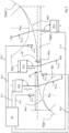
- a device 1 (hereinafter also referred to as a transport device) is shown, by means of which containers 2 are conveyed on a multiply deflected transport path TS.
- the device 1 comprises a plurality of transport elements, namely in the embodiment shown a first transport element TE1, a second transport element TE2 which adjoins the first transport element TE1 in transport direction A, and a third transport element TE3 which in turn adjoins the second transport element TE2 in transport direction A.
- the transport elements TE1 - TE3 are, for example, rotationally driven transport elements, i.e. the transport elements TE1 - TE3 are each driven to rotate about a vertical machine axis.
- Container fixing means for example in the form of container receptacles or grippers, are provided on the circumference of the transport elements TE1 - TE3, by means of which the respective container 2 is held on the respective transport element TE1 - TE3 during its transport.
- the transport elements TE1 - TE3 can partly be designed for container handling.
- the first transport element TE1 can be a filler, in particular a can filler, on which empty containers, in particular cans, are filled with a filling material.
- the third transport element TE3 can be, for example, a capper, with which closure elements, for example screw caps or crown caps, are applied to the container mouth in order to close the container opening.
- the second transport element TE2 arranged between the first and third transport elements TE1, TE3 can be, for example, a transfer star, on which no container treatment takes place, but with which the filled but still open containers 2 are transferred to the transport element TE3. It is understood that the present invention is not limited to this embodiment, but there are a variety of possible uses for devices for container treatment.
- the second transport element TE2 can also be designed as a linear conveyor, by means of which the containers 2 essentially in a straight line or alternatively in a curve along the transport route TS.
- the transport path TS on which the containers 2 are conveyed is, for example, diverted several times.
- the transport path TS has several circular arc-shaped or essentially circular arc-shaped transport path sections. Between these transport path sections there are turning points WP at which the curvature behavior of the transport path TS changes significantly, for example from a left-hand curve to a right-hand curve or vice versa. This change in the curvature behavior is also referred to as a curve change.
- a transverse jolt disadvantageously occurs on the container 2, which can lead, for example, in the case of filled but not yet closed containers 2, to the filling material spilling out of the still open container opening.
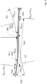
- Figure 2 is a section of the transport route TS of the Figure 1 in the area of the dashed oval, i.e. a section of the transport route TS in the transfer area between the first and second transport element TE1, TE2 with a first, a second and a third transition curve section ÜKA1, ÜKA2, ÜKA3.
- the transport route TS has a first transport route section TSA1, a second transport route section TSA2 and a third transport route section TSA3 located between the first and second transport route sections TSA1, TSA2.
- the first and second transport elements TE1, TE2 are connected to one another via the transport route section TSA consisting of the first, second and third transport route sections TSA1, TSA2, TSA3.
- the first transport section TSA1 and the second transport section TSA2 have in particular a circular arc shape, ie the curvature of the curve of the transport section TS in this first or second transport section TSA1, TSA2 is constant or almost constant. However, the curvature and the direction of curvature are different.
- the first transport section TSA1 in the embodiment shown is curved to the left and the second transport section TSA2 is curved to the right. formed.
- the radius of curvature along the first and second transport path sections TSA1, TSA2 corresponds to a respective radius R TE1 , R TE2 of the associated transport element TE1, TE2 on which the containers 2 are transported.
- the transport path TS along the first transport path section TSA1 has a radius of curvature that corresponds to the radius R TE1 of the first transport element TE1
- along the second transport path section TSA2 has a radius of curvature that corresponds to the radius R TE2 of the second transport element TE2.
- the radii R TE1 , R TE2 are thus predetermined by the respective radius of curvature of the corresponding transport element TE1, TE2 and thus cannot be changed or adjusted.
- the transport section TS has the third transport section TSA3 in the transfer area between the first and second transport section TSA1, TSA2, which according to the invention has at least one transition curve section ÜKA1, ÜKA2, ÜKA3 with an adjustable curved path.
- the third transport section TSA3 in the at least one transition curve section ÜKA1, ÜKA2, ÜKA3 is adjustable, i.e. changeable, relative to the first and second transport sections TSA1, TSA2, which cannot be changed in their respective movement paths.
- the relative adjustability of the third transport section TSA3 along the at least one transition curve section ÜKA1, ÜKA2, ÜKA3 relative to the adjacent first or second transport section TSA1, TSA2 enables a high degree of flexibility in adapting the device according to the invention to a wide variety of filling materials with different mechanical properties such as, for example, viscosity, adhesion behavior, internal damping of the liquid, but also adaptation to the performance (containers filled per hour) of the container treatment machine.
- the curvature of the curved path of the at least one transitional curve section ÜKA1, ÜKA2, ÜKA3 is designed to be adjustable in a motor-controlled and/or regulated manner by means of at least one adjusting device 50.1, 50.2, 50.3.
- At least one length L1, L2, L3 and/or at least one radius R ÜKA1, ÜKA2, ÜKA3 and/or at least one center point MP1, MP2, MP3 of the associated radius R ÜKA1, ÜKA2, ÜKA3 in an X and/or Y direction of the curvature of the curved path of the at least one transitional curve section ÜKA1, ÜKA2, ÜKA3 can be designed to be motor-adjustable by means of the at least one adjusting device 50.1, 50.2, 50.3.
- the containers 2 are guided during their transport at least along the third transport section TSA3 of the transport route TS in a lane 5 which is delimited on both sides by guide railings 4 and which specifies the curved path of the at least one transitional curved section ÜKA1, ÜKA2, ÜKA3.
- a lane 5 is formed between the outer and inner guide railings 4, in which the containers 2 are guided at least along the third transport section TSA3 and thus along the at least one transitional curved section ÜKA1, ÜKA2, ÜKA3 of the transport route TS.
- the curved path of the at least one transitional curved section ÜKA1, ÜKA2, ÜKA3 specified by the guide railings 4 is designed to be motor-adjustable by means of the at least one adjusting device 50.1, 50.2, 50.3.
- the at least one adjustment device 50.1, 50.2, 50.3 can have an eccentric device which adjusts the curved path of the at least one transition curve section ÜKA1, ÜKA2, ÜKA3 predetermined by the guide rails 4 at least along the third transport route section TSA3 by moving the guide rails 4 relative to one another, so that at least a length L1, L2, L3 and/or at least a radius R ÜKA1 , ÜKA2 , ÜKA3 and/or at least a center point MP1, MP2, MP3 of the associated radius R ÜKA1 , ÜKA2 , ÜKA3 is changed in an X and/or Y direction of the curvature of the curved path of the at least one transition curve section ÜKA1, ÜKA
- the at least one adjusting device 50.1, 50.2, 50.3 can also initiate an adjusting movement on the guide railings 4 by means of a joint device for adjusting the at least one length L1, L2, L3 and/or the at least one radius R ÜKA1 , ÜKA2 , ÜKA3 and/or the at least one center point MP1, MP2, MP3 of the associated radius R ÜKA1 , ÜKA2 , ÜKA3 in an X and/or Y direction of the curvature of the curved path of the at least one transition curve section ÜKA1, ÜKA2, ÜKA3.
- the at least one adjusting device 50.1, 50.2, 50.3 can also be designed as a linear actuator.
- the at least one transition curve section ÜKA1, ÜKA2, ÜKA3 of the third transport section TSA3 is assigned a plurality of adjustment devices 50.1, 50.2, 50.3, which are provided at a distance from one another along the at least one transition curve section ÜKA1, ÜKA2, ÜKA3.
- the at least one adjustment device 50.1, 50.2, 50.3 can be electrically connected to a control and evaluation device 52 via a control line 51.1, 51.2, 51.3 and can be designed to be controllable and/or regulated by means of this.
- a first sensor device 53.1, 53.2, 53.3 is preferably provided, which is arranged in a fixed position in the area of the third transport section TSA3.
- the at least one sensor device 53.1, 53.2, 53.3 is preferably designed as an optical sensor device, for example a video camera, and is also electrically connected to the electronic control and evaluation device 52 via a corresponding signal line 54.1, 54.2, 54.3.
- the at least one sensor device 53.1, 53.2, 53.3 each has a stationary detection area, preferably a stationary image detection area, by means of which the reaching of an actual sloshing height IH along the third transport section TSA3 on the respective container 2 can be detected.
- the detection area is preferably set such that the actual sloshing height IH of several, for example four, containers 2 can be detected simultaneously.
- the at least one sensor device 53.1, 53.2, 53.3 is designed to detect an actual sloshing height IH of the respective container 2 in the stationary detection area and to compare it with a target sloshing height SH stored there by means of an evaluation electronics stored in the electronic control and evaluation device 52 and to generate a signal from any deviation which the electronic control and evaluation device 52 controls via a control line 51.1, 51.2, 51.3 of the relevant adjustment devices 50.1, 50.2, 50.3 in order to adjust at least one length L1, L2, L3 and/or at least one radius R ÜKA1 , ÜKA2 , ÜKA3 and/or at least one center point MP1, MP2, MP3 of the associated radius R ÜKA1 , ÜKA2 , ÜKA3 in an X and/or Y direction of the curvature of the curved path of the at least one transition curve section ÜKA1, ÜKA2, ÜKA3 by means of the at least one adjustment device 50.1, 50.2, 50.3.
- the control and evaluation device can also be used to use the signal generated depending on the deviation between the actual sloshing height and the target sloshing height to change the performance (containers transported per unit of time) of the device for transporting containers, i.e. to increase and/or decrease it. In other words, this means that performance is controlled depending on the actual sloshing height detected by the at least one sensor device.
- one or more sensor devices can be arranged to record the actual sloshing height.
- This procedure makes it possible to operate the overall performance of the container transport device as close to its maximum performance (containers transported per unit of time) as possible by monitoring all critical sloshing points.
- the device for transporting containers can initially be started with a transport performance that is designed to be lower, from whose possible maximum performance (containers transported per unit of time) and the actual sloshing height are recorded by means of the at least one sensor device.
- the performance (containers transported per unit of time) of the device can then be changed, in particular increased, until the actual sloshing height corresponds to the target sloshing height.
- the curvature of the curved path of the at least one transition curve section can be adjusted by means of the at least one adjustment device in the manner described in more detail above.
- these two steps are carried out repeatedly in an iteration process and the performance of the device is increased after each run through an iteration loop so that the maximum performance of the device (containers transported per unit of time) is approached as closely as possible.
- the device for transporting containers is initially started with a lower performance, from which the possible maximum performance (containers transported per unit of time) and the actual sloshing height are recorded by means of the at least one sensor device.
- the curvature of the curved path of the at least one transition curve section is first adjusted by means of the at least one adjustment device in the manner described in more detail above and then, depending on the signal generated by the deviation between the actual sloshing height and the target sloshing height, the performance (containers transported per unit of time) of the device for transporting containers can be changed, in particular increased, until the actual sloshing height corresponds to the target sloshing height.
- these two steps are also repeated in an iteration process and the performance of the device is increased after each run through an iteration loop so that the maximum performance of the device (containers transported per unit of time) is approached as closely as possible.
- the third transport section TSA3 has a first and second transition curve section ÜKA1, ÜKA2, each of which has a separately and independently adjustable curved path.
- the third transport section TSA3 in this embodiment is divided into two transition curve sections ÜKA1, ÜKA2, each of which forms a curved path that can be adjusted independently of one another.
- a first length L1 and/or a first radius R ÜKA1 and/or a first center point MP1, MP2, MP3 of the associated first radius R ÜKA1 can be designed to be motor-adjustable in an X and/or Y direction of the curvature of the curved path of the first transitional curved section ÜKA1 by means of at least one first adjusting device 50.1 and a second length L2 and/or a second radius R ÜKA2 and/or a second center point MP2 of the associated second radius R ÜKA2 can be motor-adjustable in an X and/or Y direction of the curvature of the curved path of the second transitional curved section ÜKA2 by means of at least one second adjusting device 50.2.
- the third transport section TSA3 has a first, a second and a third transition curve section ÜKA1, ÜKA2, ÜKA3, which each have a separately and independently adjustable curved path.
- the curved paths formed by the respective transition curve sections ÜKA1, ÜKA2, ÜKA3 are independently adjustable, i.e. changeable.
- a third length L3 and/or a third radius R ÜKA3 and/or a third center point MP3 of the associated third radius R ÜKA3 can be designed to be motor-adjustable in an X and/or Y direction of the curvature of the curved path of the third transition curve section ÜKA3 by means of at least one third adjustment device 50.3.
- the first and/or second and/or third transition curve section ÜKA1, ÜKA2, ÜKA3 are set with a different length L1, L2, L3 and/or radius R ÜKA1 , ÜKA2 , ÜKA3 and/or center point MP1, MP2, MP3 of the associated radius R ÜKA1 , ÜKA2 , ÜKA3 in an X and/or Y direction of the curvature of the curved path.
- At least one transition curve section ÜKA1, ÜKA2, ÜKA3 of the third transport section TSA3 is advantageously designed as a clothoid section and/or a Blossbogen section, the course of which is selected to be clothoid-shaped or Blossbogen-shaped.
- the third transport section TSA3 has in the embodiment shown the Figure 3 two clothoid sections KA1, KA2.
- the first transition curve section ÜKA1 is designed as clothoid section KA1 and the second transition curve section ÜKA2 is designed as clothoid section KA2.
- the clothoid sections KA1, KA2 each form segments of a clothoid in order to be able to achieve a transfer between the first and second transport element TE1, TE2 with as little transverse jolt as possible.
- the first clothoid section KA1 is connected directly to the first transport section TSA1 and ends after a clothoid length KL KA1 at a turning point WP, at which a change in the curvature of the transport section TS takes place, ie the curvature of the transport section TS changes, for example, from curved to the left to curved to the right.
- This turning point WP is followed by the second clothoid section KA2 follows, which after a clothoid length KL KA2 merges into the second transport section TSA2.
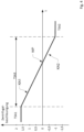
- Fig.4 shows the course of the centrifugal acceleration acting on a container 2 over time as the container 2 passes through the Fig.3 shown section of the transport section TS.
- the value of the centrifugal acceleration is constant.
- the centrifugal acceleration in these transport section sections TSA1, TSA2 is oppositely directed and in this example of a different magnitude, which is expressed by the difference in the signs of the centrifugal acceleration values and the numerical values.
- the clothoid sections KA1, KA2 are designed or dimensioned in such a way that the centrifugal acceleration in the third transport section TSA3 preferably changes linearly or essentially linearly from the centrifugal acceleration value in the area of the first transport section TSA1 to the centrifugal acceleration value in the area of the second transport section TSA2. This allows the container to be transferred from the first transport element TE1 to the second transport element TE2 with significantly reduced transverse thrust.
- the change in curvature i.e. the direction of the curvature, takes place at the turning point WP.
- the third transport section TSA3 can only have a single clothoid section.
- the first clothoid section KA1 shown can be replaced by a straight transport section.
- the third transport section TSA3 can have a straight transport section between the two clothoid sections KA1, KA2.
- the shape of the third transport section TSA3 can be depending on the respective conditions, for example the diameter of the transport elements TE1, TE2.
- KL is the clothoid length and R is the radius of curvature at the end of the clothoid section, also called clothoid radius.
- TW tangent angle between the main tangent HT at the beginning of the clothoid (ie at the turning point WP) and the tangent at any curve point of the clothoid.
- the clothoid parameter A TW ⁇ 2 ⁇ R 2
- TK is the diameter of the transport element TE1, TE2 from which the clothoid section branches off or to which the clothoid section connects.
- the clothoid radius R of the clothoid section KA1 is preferably half the diameter TK of the transport element TE1 and the clothoid radius R of the clothoid section KA2 is preferably half the diameter TK of the transport element TE2.
- the tangent angle TW KA1 , TW KA2 of the tangent in the transition of the respective clothoid section KA1, KA2 to the circular-arc transport section TSA1, TSA2 is advantageously in the range between 0.06 rad and 0.5 rad, preferably between 0.1 rad and 0.4 rad.
- a value of the tangent angle TW of 0.2 rad is particularly preferred, since this means that the axis distances of the transport elements and/or the gripper stroke, which is carried out in the area of the third transport section TSA3, are in ranges that are easily realizable in practice, ie do not become too large.
- the clothoid parameter A is preferably selected in the range between 125 mm and 250 mm, preferably in the range between 150 mm and 200 mm, particularly preferably in the range between 170 mm and 180 mm, in particular 177 mm.
- the clothoid length KL is preferably in the range between 50 mm and 250 mm, particularly preferably between 100 mm and 200 mm.
- the aforementioned parameterization of at least one clothoid section ensures that the container is transferred between the transport elements with as little jerking as possible.
- the transfer of the container 2 between the transport elements TE1 and TE2 or the transport elements TE2 and TE3 along the path of a transition curve section or a transition curve as described above on the transport section TSA3 can be achieved in particular by a transport element TE2 in the form of a transfer star, which has container fixing means, in particular container grippers, which are radially displaceable in relation to the machine axis MA, about which this transport element TE2 is rotationally driven.
- the container grippers can be designed such that they can be moved between a radially inner position and a radially outer position. are displaceable.
- the radial displacement of the container gripper is preferably carried out by means of a cam control, ie at least one control cam.
- control cam is provided in a stationary manner and a roller provided on the container gripper interacts with the control cam in such a way that the container gripper is brought radially inwards or outwards into the displacement position depending on the angular position of the rotor, so that the container on the Fig.2 shown curve in the area of the transport route section TSA3.
- the container gripper is positioned radially outward for receiving the container in the transfer area between the transport section TSA1 and TSA3 and is then retracted radially in the direction of the machine axis MA of the second transport element TE2 during the movement through the third transport section TSA3 so that the container follows the desired transport path having at least one transition curve section.
- the container gripper is moved radially outward in the opposite way so that the container is transferred to the third transport element TE3 in a transport path having at least one clothoid-shaped transition curve section.
- the container gripper After being transferred to the third transport element TE3, the container gripper can remain in its radially outward position or the position can be adjusted slightly until the respective container gripper again picks up a container from the first transport element TE1. Alternatively, it is possible for the container gripper to be retracted radially inwards after the container has been transferred to the third transport element TE3 and only moved radially outwards again shortly before a new container is picked up by the first transport element TE1.
- transition arch in the form of a clothoid or clothoid curve was described.
- another suitable transition arch with a kink-free, continuously increasing or decreasing change in curvature can also be provided, in particular a transition arch in the form of a Bloss arch or Bloss arch section.
- Combinations of a Bloss arch/Bloss arch section and a clothoid or a clothoid section are also conceivable in principle.
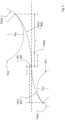
- Figure 5 shows analogous to Figure 3 a section of the transport route TS of the Figure 1 in the area of the dashed oval, i.e. a section of the transport section TS in the transfer area between the first and second transport element TE1, TE2, in which at least one transition curve section ÜKA1, ÜKA2 of the third transport section TSA3 is designed as a clothoid section and/or Blossbogen section BA1, BA2.
- This transfer area has two Blossbogen sections BA1, BA2, by means of which a transverse-jerk-free or essentially transverse-jerk-free transfer of the containers is realized.
- a container conveyed from the first transport element TE1 to the second transport element TE2 passes through the third transport section TSA3, which in the embodiment shown has a first Blossbogen section BA1 and a second Blossbogen section BA2.
- R is a radius of a connecting circular arc, ie for example the radius R TE1 , R TE2 of the respective transport element TE1, TE2, towards which the Blossbogen section forms the transition.
- I forms an intermediate length of a transition arc section viewed from a transition arc start ÜA (also referred to as turning point WP of the third transport section TSA3) (in the exemplary embodiment shown, the intermediate lengths I 1 , I 2 of the respective Blossbogen sections BA1, BA2), and L forms the total length of the transition arc or the Blossbogen section (in the exemplary embodiment shown, the lengths L 1 , L 2 of the respective Blossbogen sections BA1, BA2).
- ÜA also referred to as turning point WP of the third transport section TSA3
- L forms the total length of the transition arc or the Blossbogen section (in the exemplary embodiment shown, the lengths L 1 , L 2 of the respective Blossbogen sections BA1, BA2).
Landscapes
- Engineering & Computer Science (AREA)
- Mechanical Engineering (AREA)
- Specific Conveyance Elements (AREA)
- Control Of Conveyors (AREA)
- Feeding Of Articles To Conveyors (AREA)
- Branching, Merging, And Special Transfer Between Conveyors (AREA)
Claims (19)
- Dispositif (1) pour transporter des contenants (2) sur un parcours de transport (TS) dans une direction de transport (A), comprenant au moins un premier élément de transport (TE1) et un deuxième élément de transport (TE2), qui sont reliés par l'intermédiaire d'une section de parcours de transport (TSA) le long du parcours de transport (TS), dans lequel la section de parcours de transport (TSA) présente une première et une deuxième section de parcours de transport (TSA1, TSA2), dont au moins la première et/ou la deuxième section de parcours de transport (TSA1, TSA2) est réalisée de manière partiellement circulaire et dans lequel une troisième section de parcours de transport (TSA3) est prévue le long du parcours de transport (TS) entre la première et la deuxième section de parcours de transport (TSA1, TSA2), dans lequel la troisième section de parcours de transport (TSA3) présente au moins une section de courbe de transition (ÜKA1, ÜKA2, ÜKA3) avec une trajectoire courbe ajustable, et dans lequel la courbure de la trajectoire courbe de l'au moins une section de courbe de transition (ÜKA1, ÜKA2, ÜKA3) est réalisée de manière à pouvoir être réglée de manière commandée et/ou régulée de façon motorisée respectivement au moyen d'au moins un système d'ajustement (50.1, 50.2, 50.3) du dispositif (1), caractérisé en ce qu'au moins un système de capteur (53.1, 53.2, 53.3) relié électriquement au système d'ajustement (50.1, 50.2, 50.3) correspondant par l'intermédiaire d'un système de commande et d'évaluation (52) du dispositif (1) est prévu, qui est réalisé pour acquérir une hauteur de ballottement réelle (IH) du contenant (2) respectif dans une zone d'acquisition fixe et pour la comparer à une hauteur de ballottement de consigne (SH) stockée dans celui-ci au moyen d'une électronique d'évaluation mise en mémoire dans le système de commande et d'évaluation (52) électronique et pour produire un signal à partir d'un écart éventuel et pour commander les systèmes d'ajustement (50.1, 50.2, 50.3) concernés, afin de provoquer un ajustement d'au moins une longueur (L1, L2, L3) et/ou d'au moins un rayon (RÜKA1, ÜKA2, ÜKA3) et/ou d'au moins un centre (MP1, MP2, MP3) du rayon (RÜKA1, ÜKA2, ÜKA3) associé nécessaire sur l'écart entre la hauteur de ballottement réelle (IH) et la hauteur de ballottement de consigne (SH) dans une direction X et/ou Y de la courbure de la trajectoire courbe de l'au moins une section de courbe de transition (ÜKA1, ÜKA2, ÜKA3) au moyen de l'au moins un système d'ajustement (50.1, 50.2, 50.3).
- Dispositif (1) selon la revendication 1, caractérisé en ce qu'au moins une longueur (L1, L2, L3) et/ou au moins un rayon (RÜKA1, ÜKA2, ÜKA3) et/ou au moins un centre (MP1, MP2, MP3) du rayon (RÜKA1, ÜKA2, ÜKA3) associé dans une direction X et/ou Y de la courbure de la trajectoire courbe de l'au moins une section de courbe de transition (ÜKA1, ÜKA2, ÜKA3) est réalisé(e) de manière à pouvoir être réglé(e) de façon motorisée au moyen de l'au moins un système d'ajustement (50.1, 50.2, 50.3).
- Dispositif (1) selon l'une quelconque des revendications précédentes, caractérisé en ce que les contenants (2) sont guidés le long de la première ou troisième section de parcours de transport (TSA1, TSA3) par des rampes de guidage (4), dans lequel la trajectoire courbe de l'au moins une section de courbe de transition (ÜKA1, ÜKA2, ÜKA3) prédéfinie par les rampes de guidage (4) est réalisée de manière à pouvoir être réglée de façon motorisée au moyen de l'au moins un système d'ajustement (50.1, 50.2, 50.3).
- Dispositif (1) selon l'une quelconque des revendications précédentes, caractérisé en ce que respectivement plusieurs systèmes d'ajustement (50.1, 50.2, 50.3), qui sont prévus de manière espacée les uns des autres le long de de l'au moins une section de courbe de transition (ÜKA1, ÜKA2, ÜKA3), sont associés à l'au moins une section de courbe de transition (ÜKA1, ÜKA2, ÜKA3) de la troisième section de parcours de transport (TSA3).
- Dispositif (1) selon l'une quelconque des revendications précédentes, caractérisé en ce que le système de commande et d'évaluation (52) est réalisé pour utiliser le signal produit en fonction de l'écart entre la hauteur de ballottement réelle (IH) et la hauteur de ballottement de consigne (SH), afin de modifier, en particulier de commander et/ou de réguler la puissance du dispositif (1).
- Dispositif (1) selon l'une quelconque des revendications précédentes, caractérisé en ce que la troisième section de parcours de transport (TSA3) présente une première et une deuxième section de courbe de transition (ÜKA1, ÜKA2), qui présentent respectivement une trajectoire courbe pouvant être réglée séparément et indépendamment l'une de l'autre.
- Dispositif (1) selon la revendication 6, caractérisé en ce qu'une première longueur (L1) et/ou un premier rayon (RÜKA1) et/ou un premier centre (MP1) du premier rayon (RÜKA1) associé dans une direction X et/ou Y de la courbure de la trajectoire courbe de la première section de courbe de transition (ÜKA1) est réalisé de manière à pouvoir être réglé(e) de façon motorisée au moyen d'au moins un premier système d'ajustement (50.1) et une deuxième longueur (L2) et/ou un deuxième rayon (RÜKA2) et/ou un deuxième centre (MP2) du deuxième rayon (RÜKA2) associé dans une direction X et/ou Y de la courbure de la trajectoire courbe de la deuxième section de courbe de transition (ÜKA2) est réalisé(e) de manière à pouvoir être réglé(e) de façon motorisée au moyen d'au moins un deuxième système d'ajustement (50.2).
- Dispositif (1) selon la revendication 6 ou 7, caractérisé en ce que la troisième section de parcours de transport (TSA3) présente une première, une deuxième ainsi qu'une troisième section de courbe de transition (ÜKA1, ÜKA2, ÜKA3), qui présentent respectivement une trajectoire courbe pouvant être réglée séparément et indépendamment les unes des autres.
- Dispositif (1) selon l'une quelconque des revendications 6 à 8, caractérisé en ce qu'une troisième longueur (L3) et/ou un troisième rayon (RÜKAS) et/ou un troisième centre (MP3) du troisième rayon (RÜKA3) associé dans une direction X et/ou Y de la courbure de la trajectoire courbe de la troisième section de courbe de transition (ÜKA3) est réalisé(e) de manière à pouvoir être réglé(e) de façon motorisée au moyen d'au moins un troisième système d'ajustement (50.3).
- Dispositif (1) selon l'une quelconque des revendications précédentes, caractérisé en ce qu'au moins une section de courbe de transition (ÜKA1, ÜKA2, ÜKA3) de la troisième section de parcours de transport (TSA3) est réalisée comme section de clothoïde (KA1, KA2) et/ou section d'arc de Bloss (BA1, BA2).
- Dispositif (1) selon la revendication 10, caractérisé en ce que l'au moins une section de clothoïde (KA1, KA2) est décrite par les formules suivantes :


- Dispositif (1) selon la revendication 11, caractérisé en ce que le paramètre de clothoïde A est sélectionné dans la plage comprise entre 125 mm et 250 mm, en particulier dans la plage comprise entre 150 mm et 200 mm, de manière particulièrement préférée dans la plage comprise entre 170 mm et 180 mm.
- Dispositif (1) selon la revendication 11 ou 12, caractérisé en ce que l'angle de tangente TW est sélectionné dans la plage comprise entre 0,06 rad et 0,5 rad, en particulier dans la plage comprise entre 0,1 rad et 0,4 rad, de manière particulièrement préférée jusqu'à 0,2 rad.
- Dispositif (1) selon la revendication 10, caractérisé en ce que la courbure de l'au moins une section d'arc de Bloss (BA1, BA2) est décrite par la formule suivante :

- Dispositif (1) selon l'une quelconque des revendications 10 à 14, caractérisé en ce que la longueur de clothoïde KL et/ou la longueur totale de l'arc de transition L se situe dans la plage comprise entre 50 mm et 250 mm, en particulier dans la plage comprise entre 100 mm et 200 mm.
- Procédé pour transporter des contenants (2) sur un parcours de transport (TS) avec un dispositif (1) selon l'une quelconque des revendications précédentes 1 à 15 dans une direction de transport (A) au moyen du premier et du deuxième élément de transport (TE1, TE2), qui sont reliés par l'intermédiaire d'une section de parcours de transport (TSA) le long du parcours de transport (TS), dans lequel la section de parcours de transport (TSA) présente une première et une deuxième section de parcours de transport (TSA1, TSA2), dont au moins la première et/ou la deuxième section de parcours de transport (TSA1, TSA2) est réalisée de manière partiellement circulaire et dans lequel une troisième section de parcours de transport (TSA3) est prévue le long du parcours de transport (TS) entre la première et la deuxième section de parcours de transport (TSA1, TSA2), dans lequel la troisième section de parcours de transport (TSA3) présente au moins une section de courbe de transition (ÜKA1, ÜKA2, ÜKS3), dont la trajectoire courbe est prévue de manière ajustable.
- Procédé selon la revendication 16, caractérisé en ce qu'un signal produit en fonction de l'écart entre la hauteur de ballottement réelle (IH) du contenant (2) respectif et la hauteur de ballottement de consigne (SH) est utilisé afin de modifier, en particulier de commander et/ou de réguler, la puissance du dispositif (1).
- Procédé selon la revendication 17, selon lequel le dispositif (1) est démarré tout d'abord avec une puissance de transport qui est réalisée de manière plus faible à partir de sa puissance maximale possible et la hauteur de ballottement réelle (IH) est acquise au moyen de l'au moins un système de capteur (53.1, 53.2, 53.3), selon lequel ensuite en fonction du signal produit par l'écart entre la hauteur de ballottement réelle (IH) et la hauteur de ballottement de consigne (SH), la puissance est modifiée aussi longtemps que la hauteur de ballottement réelle (IH) ne correspond pas à la hauteur de ballottement de consigne (SH) et après cela un ajustement de la courbure de la trajectoire courbe de l'au moins une section de courbe de transition s'effectue au moyen de l'au moins un système d'ajustement (50.1, 50.2, 50.3).
- Procédé selon la revendication 17 ou 18, selon lequel le dispositif (1) est démarré tout d'abord avec une puissance de transport qui est réalisée de manière plus faible à partir de sa puissance maximale possible et la hauteur de ballottement réelle (IH) est acquise au moyen de l'au moins un système de capteur (53.1, 53.2, 53.3), selon lequel tout d'abord un ajustement de la courbure de la trajectoire courbe de l'au moins une section de courbe de transition s'effectue au moyen de l'au moins un système d'ajustement (50.1, 50.2, 50.3) et après cela en fonction du signal produit par l'écart entre la hauteur de ballottement réelle (IH) et la hauteur de ballottement de consigne (SH) modifie la puissance du dispositif pour transporter des contenants (2) aussi longtemps que la hauteur de ballottement réelle (IH) correspond à la hauteur de ballottement de consigne (SH).
Applications Claiming Priority (2)
| Application Number | Priority Date | Filing Date | Title |
|---|---|---|---|
| DE102019117377.9A DE102019117377A1 (de) | 2019-06-27 | 2019-06-27 | Vorrichtung und Verfahren zum Transportieren von Behältern |
| PCT/EP2020/067409 WO2020260227A1 (fr) | 2019-06-27 | 2020-06-23 | Dispositif et procédé de transport de contenants |
Publications (2)
| Publication Number | Publication Date |
|---|---|
| EP3990375A1 EP3990375A1 (fr) | 2022-05-04 |
| EP3990375B1 true EP3990375B1 (fr) | 2024-09-18 |
Family
ID=71138743
Family Applications (1)
| Application Number | Title | Priority Date | Filing Date |
|---|---|---|---|
| EP20734512.5A Active EP3990375B1 (fr) | 2019-06-27 | 2020-06-23 | Dispositif et procédé de transport de contenants |
Country Status (5)
| Country | Link |
|---|---|
| US (1) | US12017864B2 (fr) |
| EP (1) | EP3990375B1 (fr) |
| CN (1) | CN114174199B (fr) |
| DE (1) | DE102019117377A1 (fr) |
| WO (1) | WO2020260227A1 (fr) |
Families Citing this family (2)
| Publication number | Priority date | Publication date | Assignee | Title |
|---|---|---|---|---|
| DE102019117382A1 (de) * | 2019-06-27 | 2020-12-31 | Khs Gmbh | Behälterbehandlungsvorrichtung |
| DE102022117955A1 (de) | 2022-07-19 | 2024-01-25 | Khs Gmbh | Anlage zur Behandlung von Dosen und Verfahren zum Betrieb der Anlage |
Family Cites Families (22)
| Publication number | Priority date | Publication date | Assignee | Title |
|---|---|---|---|---|
| JPS5213441A (en) * | 1975-07-23 | 1977-02-01 | Nippon Steel Corp | Inert gas welding wire for high tenacity stainless steel used at low temperatures |
| JP2974085B2 (ja) * | 1990-12-13 | 1999-11-08 | 三菱重工業株式会社 | 充填機のガイド装置 |
| JPH05213441A (ja) * | 1992-02-04 | 1993-08-24 | Shibuya Kogyo Co Ltd | 可変ガイド装置 |
| CN1224402A (zh) * | 1996-05-13 | 1999-07-28 | Ipt维恩费尔登股份公司 | 悬挂输送容器的方法和实施此方法的装置 |
| JP4350189B2 (ja) * | 1999-01-21 | 2009-10-21 | 澁谷工業株式会社 | 方向転換ガイドの自動ガイド幅調整装置 |
| JP3829578B2 (ja) * | 2000-04-11 | 2006-10-04 | 東洋製罐株式会社 | 充填装置 |
| GB2415419B (en) * | 2004-06-21 | 2007-06-20 | Diageo Plc | Automated handling line guide rail assembly |
| EP1659367B1 (fr) * | 2004-11-19 | 2008-09-03 | Harman Becker Automotive Systems GmbH | Navigation d'un véhicule pour l'avertissement intégré de virages basé sur les modèles clothoides |
| DE102006013800C5 (de) * | 2006-03-24 | 2010-04-15 | Khs Ag | Transportsystem für Flaschen oder dergleichen Behälter sowie Anlage zum Behandeln von Flaschen oder dergleichen Behälter |
| DE102006054099A1 (de) * | 2006-11-15 | 2008-05-21 | Khs Ag | Verfahren zur Inspektion oder Überwachung von Flaschen oder dergleichen Behälter sowie Vorrichtung zur Inspektion von Flaschen oder dergleichen Behälter |
| DE102008052768A1 (de) * | 2008-10-22 | 2010-04-29 | Krones Ag | Vorrichtung zum Transportieren von Behältnissen |
| US8186503B1 (en) * | 2010-09-23 | 2012-05-29 | SEETECH Systems, Inc. | Adjustable curved fence assembly |
| DE102011010955B4 (de) * | 2011-02-10 | 2013-01-31 | Khs Gmbh | Verschiebbare Transportsterne |
| DE102011115512A1 (de) * | 2011-10-11 | 2013-04-11 | Khs Gmbh | Transferstern |
| JP6424511B2 (ja) * | 2014-08-08 | 2018-11-21 | 東洋製罐株式会社 | 物品の搬送方法及びその装置 |
| EP2987764B1 (fr) * | 2014-08-20 | 2018-09-19 | Krones AG | Dispositif destiné à éviter les débordements pour des remplisseuses de moule |
| AT516278B1 (de) * | 2014-10-22 | 2016-04-15 | System 7 Railsupport Gmbh | Verfahren zur Messung und Darstellung der Gleisgeometrie einer Gleisanlage |
| JP6716858B2 (ja) * | 2015-01-15 | 2020-07-01 | 東洋製罐株式会社 | 缶体の充填巻締装置及び充填巻締方法 |
| NL2015573B1 (en) * | 2015-10-06 | 2017-05-01 | Sluis Cigar Machinery Bv | Transfer system for transferring items. |
| DE102015224731A1 (de) * | 2015-12-09 | 2017-06-14 | Krones Ag | Behandlungsmaschine für Behälter |
| DE102017112220A1 (de) * | 2017-06-02 | 2018-12-27 | Khs Gmbh | Vorrichtung und Verfahren zum Transportieren von Behältern |
| EP3461783B1 (fr) * | 2017-09-29 | 2019-11-13 | B&R Industrial Automation GmbH | Équipement de levage et procédé de commande d'un équipement de levage |
-
2019
- 2019-06-27 DE DE102019117377.9A patent/DE102019117377A1/de not_active Withdrawn
-
2020
- 2020-06-23 WO PCT/EP2020/067409 patent/WO2020260227A1/fr not_active Ceased
- 2020-06-23 US US17/621,297 patent/US12017864B2/en active Active
- 2020-06-23 EP EP20734512.5A patent/EP3990375B1/fr active Active
- 2020-06-23 CN CN202080054289.9A patent/CN114174199B/zh active Active
Also Published As
| Publication number | Publication date |
|---|---|
| US20220356020A1 (en) | 2022-11-10 |
| WO2020260227A1 (fr) | 2020-12-30 |
| DE102019117377A1 (de) | 2020-12-31 |
| US12017864B2 (en) | 2024-06-25 |
| EP3990375A1 (fr) | 2022-05-04 |
| CN114174199B (zh) | 2024-05-10 |
| CN114174199A (zh) | 2022-03-11 |
| BR112021025935A2 (pt) | 2022-02-08 |
Similar Documents
| Publication | Publication Date | Title |
|---|---|---|
| EP0399264B1 (fr) | Procédé et dispositif pour changer la position relative de paquets, en particulier de paquets de cigarettes parallélépipédiques du type à couvercle articulé (hinge-lid) | |
| EP2077968B1 (fr) | Parcours de transport | |
| EP3990375B1 (fr) | Dispositif et procédé de transport de contenants | |
| DE102020116779A1 (de) | Behälterbehandlungsvorrichtung | |
| WO2018219523A1 (fr) | Dispositif et procédé destinés au transport de récipients | |
| EP2110346B1 (fr) | Agencement et procédé de transport et de distribution synchrone de récipients | |
| DE102013101645B4 (de) | Transporteur für Flaschen oder dergleichen Behälter sowie Behälterbehandlungsmaschine | |
| DE102021100677A1 (de) | Verstellvorrichtung zum Verstellen von Behälterführungen | |
| EP2637808A1 (fr) | Dispositif de transport pour le transport de pièces | |
| EP3160874A1 (fr) | Convoyeur à bande avec éléments en coin destinés à modifier la courbure au niveau des roues de renvoi | |
| EP4129888B1 (fr) | Dispositif de commande d'une position de levage d'un élément de levage, dispositif de manutention de récipients et procédé de réglage d'un point de transition d'une came de commande | |
| EP1088761A1 (fr) | Dispositif pour appliquer automatiquement des poignées de transport à des marchandises | |
| EP3350107A1 (fr) | Transporteur de contenants | |
| WO2018015060A1 (fr) | Dispositif de transport | |
| EP4263396A1 (fr) | Dispositif d'alimentation en récipients et procédé de fonctionnement du dispositif d'alimentation en récipients | |
| DE102018124212A1 (de) | Förderstrecke für einen Transport einer Vielzahl von Artikeln und Verfahren zum Anpassen und/oder Betreiben einer Förderstrecke | |
| DE202007018515U1 (de) | Vorrichtung zum Transport beliebiger Teile | |
| EP1710158B1 (fr) | Procédé et dispositif pour manipuler des conteneurs | |
| EP3990376B1 (fr) | Dispositif de traitement de contenants | |
| EP3838813B1 (fr) | Dispositif de traitement des récipients avec un dispositif d'alimentation ou d'évacuation d'un récipient | |
| DE4134009A1 (de) | Verteilvorrichtung fuer eine bahnfoermige foerdereinrichtung, insbesondere einen rollen- oder kettenfoerderer, zum verteilen von transportguetern | |
| AT526279B1 (de) | Verfahren zum Fördern und Orientieren von Ausgießelementen mit Verschluss und Fördervorrichtung | |
| EP4161861B1 (fr) | Dispositif pour la fermeture des récipients | |
| DE20020364U1 (de) | Vorrichtung zum Wenden von Gegenständen | |
| WO2017005458A1 (fr) | Système de guidage de récipients dans une machine de traitement de récipients |
Legal Events
| Date | Code | Title | Description |
|---|---|---|---|
| STAA | Information on the status of an ep patent application or granted ep patent |
Free format text: STATUS: UNKNOWN |
|
| STAA | Information on the status of an ep patent application or granted ep patent |
Free format text: STATUS: THE INTERNATIONAL PUBLICATION HAS BEEN MADE |
|
| PUAI | Public reference made under article 153(3) epc to a published international application that has entered the european phase |
Free format text: ORIGINAL CODE: 0009012 |
|
| STAA | Information on the status of an ep patent application or granted ep patent |
Free format text: STATUS: REQUEST FOR EXAMINATION WAS MADE |
|
| 17P | Request for examination filed |
Effective date: 20220127 |
|
| AK | Designated contracting states |
Kind code of ref document: A1 Designated state(s): AL AT BE BG CH CY CZ DE DK EE ES FI FR GB GR HR HU IE IS IT LI LT LU LV MC MK MT NL NO PL PT RO RS SE SI SK SM TR |
|
| DAV | Request for validation of the european patent (deleted) | ||
| DAX | Request for extension of the european patent (deleted) | ||
| GRAP | Despatch of communication of intention to grant a patent |
Free format text: ORIGINAL CODE: EPIDOSNIGR1 |
|
| STAA | Information on the status of an ep patent application or granted ep patent |
Free format text: STATUS: GRANT OF PATENT IS INTENDED |
|
| INTG | Intention to grant announced |
Effective date: 20240607 |
|
| GRAS | Grant fee paid |
Free format text: ORIGINAL CODE: EPIDOSNIGR3 |
|
| GRAA | (expected) grant |
Free format text: ORIGINAL CODE: 0009210 |
|
| STAA | Information on the status of an ep patent application or granted ep patent |
Free format text: STATUS: THE PATENT HAS BEEN GRANTED |
|
| AK | Designated contracting states |
Kind code of ref document: B1 Designated state(s): AL AT BE BG CH CY CZ DE DK EE ES FI FR GB GR HR HU IE IS IT LI LT LU LV MC MK MT NL NO PL PT RO RS SE SI SK SM TR |
|
| REG | Reference to a national code |
Ref country code: GB Ref legal event code: FG4D Free format text: NOT ENGLISH |
|
| REG | Reference to a national code |
Ref country code: CH Ref legal event code: EP |
|
| REG | Reference to a national code |
Ref country code: IE Ref legal event code: FG4D Free format text: LANGUAGE OF EP DOCUMENT: GERMAN |
|
| REG | Reference to a national code |
Ref country code: DE Ref legal event code: R096 Ref document number: 502020009278 Country of ref document: DE |
|
| REG | Reference to a national code |
Ref country code: LT Ref legal event code: MG9D |
|
| PG25 | Lapsed in a contracting state [announced via postgrant information from national office to epo] |
Ref country code: NO Free format text: LAPSE BECAUSE OF FAILURE TO SUBMIT A TRANSLATION OF THE DESCRIPTION OR TO PAY THE FEE WITHIN THE PRESCRIBED TIME-LIMIT Effective date: 20241218 |
|
| PG25 | Lapsed in a contracting state [announced via postgrant information from national office to epo] |
Ref country code: GR Free format text: LAPSE BECAUSE OF FAILURE TO SUBMIT A TRANSLATION OF THE DESCRIPTION OR TO PAY THE FEE WITHIN THE PRESCRIBED TIME-LIMIT Effective date: 20241219 Ref country code: FI Free format text: LAPSE BECAUSE OF FAILURE TO SUBMIT A TRANSLATION OF THE DESCRIPTION OR TO PAY THE FEE WITHIN THE PRESCRIBED TIME-LIMIT Effective date: 20240918 |
|
| PG25 | Lapsed in a contracting state [announced via postgrant information from national office to epo] |
Ref country code: BG Free format text: LAPSE BECAUSE OF FAILURE TO SUBMIT A TRANSLATION OF THE DESCRIPTION OR TO PAY THE FEE WITHIN THE PRESCRIBED TIME-LIMIT Effective date: 20240918 |
|
| PG25 | Lapsed in a contracting state [announced via postgrant information from national office to epo] |
Ref country code: LV Free format text: LAPSE BECAUSE OF FAILURE TO SUBMIT A TRANSLATION OF THE DESCRIPTION OR TO PAY THE FEE WITHIN THE PRESCRIBED TIME-LIMIT Effective date: 20240918 |
|
| PG25 | Lapsed in a contracting state [announced via postgrant information from national office to epo] |
Ref country code: HR Free format text: LAPSE BECAUSE OF FAILURE TO SUBMIT A TRANSLATION OF THE DESCRIPTION OR TO PAY THE FEE WITHIN THE PRESCRIBED TIME-LIMIT Effective date: 20240918 |
|
| REG | Reference to a national code |
Ref country code: NL Ref legal event code: MP Effective date: 20240918 |
|
| PG25 | Lapsed in a contracting state [announced via postgrant information from national office to epo] |
Ref country code: RS Free format text: LAPSE BECAUSE OF FAILURE TO SUBMIT A TRANSLATION OF THE DESCRIPTION OR TO PAY THE FEE WITHIN THE PRESCRIBED TIME-LIMIT Effective date: 20241218 |
|
| PG25 | Lapsed in a contracting state [announced via postgrant information from national office to epo] |
Ref country code: RS Free format text: LAPSE BECAUSE OF FAILURE TO SUBMIT A TRANSLATION OF THE DESCRIPTION OR TO PAY THE FEE WITHIN THE PRESCRIBED TIME-LIMIT Effective date: 20241218 Ref country code: NO Free format text: LAPSE BECAUSE OF FAILURE TO SUBMIT A TRANSLATION OF THE DESCRIPTION OR TO PAY THE FEE WITHIN THE PRESCRIBED TIME-LIMIT Effective date: 20241218 Ref country code: LV Free format text: LAPSE BECAUSE OF FAILURE TO SUBMIT A TRANSLATION OF THE DESCRIPTION OR TO PAY THE FEE WITHIN THE PRESCRIBED TIME-LIMIT Effective date: 20240918 Ref country code: HR Free format text: LAPSE BECAUSE OF FAILURE TO SUBMIT A TRANSLATION OF THE DESCRIPTION OR TO PAY THE FEE WITHIN THE PRESCRIBED TIME-LIMIT Effective date: 20240918 Ref country code: GR Free format text: LAPSE BECAUSE OF FAILURE TO SUBMIT A TRANSLATION OF THE DESCRIPTION OR TO PAY THE FEE WITHIN THE PRESCRIBED TIME-LIMIT Effective date: 20241219 Ref country code: FI Free format text: LAPSE BECAUSE OF FAILURE TO SUBMIT A TRANSLATION OF THE DESCRIPTION OR TO PAY THE FEE WITHIN THE PRESCRIBED TIME-LIMIT Effective date: 20240918 Ref country code: BG Free format text: LAPSE BECAUSE OF FAILURE TO SUBMIT A TRANSLATION OF THE DESCRIPTION OR TO PAY THE FEE WITHIN THE PRESCRIBED TIME-LIMIT Effective date: 20240918 |
|
| PG25 | Lapsed in a contracting state [announced via postgrant information from national office to epo] |
Ref country code: NL Free format text: LAPSE BECAUSE OF FAILURE TO SUBMIT A TRANSLATION OF THE DESCRIPTION OR TO PAY THE FEE WITHIN THE PRESCRIBED TIME-LIMIT Effective date: 20240918 |
|
| PG25 | Lapsed in a contracting state [announced via postgrant information from national office to epo] |
Ref country code: PT Free format text: LAPSE BECAUSE OF FAILURE TO SUBMIT A TRANSLATION OF THE DESCRIPTION OR TO PAY THE FEE WITHIN THE PRESCRIBED TIME-LIMIT Effective date: 20250120 Ref country code: IS Free format text: LAPSE BECAUSE OF FAILURE TO SUBMIT A TRANSLATION OF THE DESCRIPTION OR TO PAY THE FEE WITHIN THE PRESCRIBED TIME-LIMIT Effective date: 20250118 |
|
| PG25 | Lapsed in a contracting state [announced via postgrant information from national office to epo] |
Ref country code: RO Free format text: LAPSE BECAUSE OF FAILURE TO SUBMIT A TRANSLATION OF THE DESCRIPTION OR TO PAY THE FEE WITHIN THE PRESCRIBED TIME-LIMIT Effective date: 20240918 Ref country code: SM Free format text: LAPSE BECAUSE OF FAILURE TO SUBMIT A TRANSLATION OF THE DESCRIPTION OR TO PAY THE FEE WITHIN THE PRESCRIBED TIME-LIMIT Effective date: 20240918 |
|
| PG25 | Lapsed in a contracting state [announced via postgrant information from national office to epo] |
Ref country code: ES Free format text: LAPSE BECAUSE OF FAILURE TO SUBMIT A TRANSLATION OF THE DESCRIPTION OR TO PAY THE FEE WITHIN THE PRESCRIBED TIME-LIMIT Effective date: 20240918 |
|
| PG25 | Lapsed in a contracting state [announced via postgrant information from national office to epo] |
Ref country code: EE Free format text: LAPSE BECAUSE OF FAILURE TO SUBMIT A TRANSLATION OF THE DESCRIPTION OR TO PAY THE FEE WITHIN THE PRESCRIBED TIME-LIMIT Effective date: 20240918 |
|
| PG25 | Lapsed in a contracting state [announced via postgrant information from national office to epo] |
Ref country code: PL Free format text: LAPSE BECAUSE OF FAILURE TO SUBMIT A TRANSLATION OF THE DESCRIPTION OR TO PAY THE FEE WITHIN THE PRESCRIBED TIME-LIMIT Effective date: 20240918 Ref country code: CZ Free format text: LAPSE BECAUSE OF FAILURE TO SUBMIT A TRANSLATION OF THE DESCRIPTION OR TO PAY THE FEE WITHIN THE PRESCRIBED TIME-LIMIT Effective date: 20240918 |
|
| PG25 | Lapsed in a contracting state [announced via postgrant information from national office to epo] |
Ref country code: SK Free format text: LAPSE BECAUSE OF FAILURE TO SUBMIT A TRANSLATION OF THE DESCRIPTION OR TO PAY THE FEE WITHIN THE PRESCRIBED TIME-LIMIT Effective date: 20240918 |
|
| REG | Reference to a national code |
Ref country code: DE Ref legal event code: R097 Ref document number: 502020009278 Country of ref document: DE |
|
| PGFP | Annual fee paid to national office [announced via postgrant information from national office to epo] |
Ref country code: DE Payment date: 20250618 Year of fee payment: 6 |
|
| PG25 | Lapsed in a contracting state [announced via postgrant information from national office to epo] |
Ref country code: DK Free format text: LAPSE BECAUSE OF FAILURE TO SUBMIT A TRANSLATION OF THE DESCRIPTION OR TO PAY THE FEE WITHIN THE PRESCRIBED TIME-LIMIT Effective date: 20240918 |
|
| PGFP | Annual fee paid to national office [announced via postgrant information from national office to epo] |
Ref country code: FR Payment date: 20250627 Year of fee payment: 6 |
|
| PLBE | No opposition filed within time limit |
Free format text: ORIGINAL CODE: 0009261 |
|
| STAA | Information on the status of an ep patent application or granted ep patent |
Free format text: STATUS: NO OPPOSITION FILED WITHIN TIME LIMIT |
|
| 26N | No opposition filed |
Effective date: 20250619 |
|
| PG25 | Lapsed in a contracting state [announced via postgrant information from national office to epo] |
Ref country code: SE Free format text: LAPSE BECAUSE OF FAILURE TO SUBMIT A TRANSLATION OF THE DESCRIPTION OR TO PAY THE FEE WITHIN THE PRESCRIBED TIME-LIMIT Effective date: 20240918 |
|
| PGFP | Annual fee paid to national office [announced via postgrant information from national office to epo] |
Ref country code: IT Payment date: 20250624 Year of fee payment: 6 |
|
| P01 | Opt-out of the competence of the unified patent court (upc) registered |
Free format text: CASE NUMBER: UPC_APP_0014568_3990375/2025 Effective date: 20251125 |
|
| REG | Reference to a national code |
Ref country code: CH Ref legal event code: H13 Free format text: ST27 STATUS EVENT CODE: U-0-0-H10-H13 (AS PROVIDED BY THE NATIONAL OFFICE) Effective date: 20260127 |
|
| PG25 | Lapsed in a contracting state [announced via postgrant information from national office to epo] |
Ref country code: MC Free format text: LAPSE BECAUSE OF FAILURE TO SUBMIT A TRANSLATION OF THE DESCRIPTION OR TO PAY THE FEE WITHIN THE PRESCRIBED TIME-LIMIT Effective date: 20240918 |
|
| PG25 | Lapsed in a contracting state [announced via postgrant information from national office to epo] |
Ref country code: LU Free format text: LAPSE BECAUSE OF NON-PAYMENT OF DUE FEES Effective date: 20250623 |
|
| GBPC | Gb: european patent ceased through non-payment of renewal fee |
Effective date: 20250623 |
|
| REG | Reference to a national code |
Ref country code: BE Ref legal event code: MM Effective date: 20250630 |
|
| PG25 | Lapsed in a contracting state [announced via postgrant information from national office to epo] |
Ref country code: GB Free format text: LAPSE BECAUSE OF NON-PAYMENT OF DUE FEES Effective date: 20250623 |
|
| PG25 | Lapsed in a contracting state [announced via postgrant information from national office to epo] |
Ref country code: IE Free format text: LAPSE BECAUSE OF NON-PAYMENT OF DUE FEES Effective date: 20250623 |
|
| PG25 | Lapsed in a contracting state [announced via postgrant information from national office to epo] |
Ref country code: BE Free format text: LAPSE BECAUSE OF NON-PAYMENT OF DUE FEES Effective date: 20250630 |
|
| PG25 | Lapsed in a contracting state [announced via postgrant information from national office to epo] |
Ref country code: CH Free format text: LAPSE BECAUSE OF NON-PAYMENT OF DUE FEES Effective date: 20250630 |