EP3990809B1 - An adjustable valve - Google Patents
An adjustable valve Download PDFInfo
- Publication number
- EP3990809B1 EP3990809B1 EP20742652.9A EP20742652A EP3990809B1 EP 3990809 B1 EP3990809 B1 EP 3990809B1 EP 20742652 A EP20742652 A EP 20742652A EP 3990809 B1 EP3990809 B1 EP 3990809B1
- Authority
- EP
- European Patent Office
- Prior art keywords
- valve
- cap
- valve cap
- adjustable
- relative
- Prior art date
- Legal status (The legal status is an assumption and is not a legal conclusion. Google has not performed a legal analysis and makes no representation as to the accuracy of the status listed.)
- Active
Links
Images




Classifications
-
- F—MECHANICAL ENGINEERING; LIGHTING; HEATING; WEAPONS; BLASTING
- F16—ENGINEERING ELEMENTS AND UNITS; GENERAL MEASURES FOR PRODUCING AND MAINTAINING EFFECTIVE FUNCTIONING OF MACHINES OR INSTALLATIONS; THERMAL INSULATION IN GENERAL
- F16K—VALVES; TAPS; COCKS; ACTUATING-FLOATS; DEVICES FOR VENTING OR AERATING
- F16K17/00—Safety valves; Equalising valves, e.g. pressure relief valves
- F16K17/02—Safety valves; Equalising valves, e.g. pressure relief valves opening on surplus pressure on one side; closing on insufficient pressure on one side
- F16K17/04—Safety valves; Equalising valves, e.g. pressure relief valves opening on surplus pressure on one side; closing on insufficient pressure on one side spring-loaded
- F16K17/06—Safety valves; Equalising valves, e.g. pressure relief valves opening on surplus pressure on one side; closing on insufficient pressure on one side spring-loaded with special arrangements for adjusting the opening pressure
-
- F—MECHANICAL ENGINEERING; LIGHTING; HEATING; WEAPONS; BLASTING
- F16—ENGINEERING ELEMENTS AND UNITS; GENERAL MEASURES FOR PRODUCING AND MAINTAINING EFFECTIVE FUNCTIONING OF MACHINES OR INSTALLATIONS; THERMAL INSULATION IN GENERAL
- F16K—VALVES; TAPS; COCKS; ACTUATING-FLOATS; DEVICES FOR VENTING OR AERATING
- F16K35/00—Means to prevent accidental or unauthorised actuation
- F16K35/10—Means to prevent accidental or unauthorised actuation with locking caps or locking bars
-
- A—HUMAN NECESSITIES
- A61—MEDICAL OR VETERINARY SCIENCE; HYGIENE
- A61M—DEVICES FOR INTRODUCING MEDIA INTO, OR ONTO, THE BODY; DEVICES FOR TRANSDUCING BODY MEDIA OR FOR TAKING MEDIA FROM THE BODY; DEVICES FOR PRODUCING OR ENDING SLEEP OR STUPOR
- A61M16/00—Devices for influencing the respiratory system of patients by gas treatment, e.g. ventilators; Tracheal tubes
- A61M16/20—Valves specially adapted to medical respiratory devices
- A61M16/201—Controlled valves
- A61M16/202—Controlled valves electrically actuated
- A61M16/203—Proportional
- A61M16/205—Proportional used for exhalation control
-
- A—HUMAN NECESSITIES
- A61—MEDICAL OR VETERINARY SCIENCE; HYGIENE
- A61M—DEVICES FOR INTRODUCING MEDIA INTO, OR ONTO, THE BODY; DEVICES FOR TRANSDUCING BODY MEDIA OR FOR TAKING MEDIA FROM THE BODY; DEVICES FOR PRODUCING OR ENDING SLEEP OR STUPOR
- A61M16/00—Devices for influencing the respiratory system of patients by gas treatment, e.g. ventilators; Tracheal tubes
- A61M16/20—Valves specially adapted to medical respiratory devices
- A61M16/201—Controlled valves
-
- A—HUMAN NECESSITIES
- A61—MEDICAL OR VETERINARY SCIENCE; HYGIENE
- A61M—DEVICES FOR INTRODUCING MEDIA INTO, OR ONTO, THE BODY; DEVICES FOR TRANSDUCING BODY MEDIA OR FOR TAKING MEDIA FROM THE BODY; DEVICES FOR PRODUCING OR ENDING SLEEP OR STUPOR
- A61M16/00—Devices for influencing the respiratory system of patients by gas treatment, e.g. ventilators; Tracheal tubes
- A61M16/20—Valves specially adapted to medical respiratory devices
- A61M16/201—Controlled valves
- A61M16/206—Capsule valves, e.g. mushroom, membrane valves
-
- F—MECHANICAL ENGINEERING; LIGHTING; HEATING; WEAPONS; BLASTING
- F16—ENGINEERING ELEMENTS AND UNITS; GENERAL MEASURES FOR PRODUCING AND MAINTAINING EFFECTIVE FUNCTIONING OF MACHINES OR INSTALLATIONS; THERMAL INSULATION IN GENERAL
- F16K—VALVES; TAPS; COCKS; ACTUATING-FLOATS; DEVICES FOR VENTING OR AERATING
- F16K1/00—Lift valves or globe valves, i.e. cut-off apparatus with closure members having at least a component of their opening and closing motion perpendicular to the closing faces
- F16K1/02—Lift valves or globe valves, i.e. cut-off apparatus with closure members having at least a component of their opening and closing motion perpendicular to the closing faces with screw-spindle
-
- F—MECHANICAL ENGINEERING; LIGHTING; HEATING; WEAPONS; BLASTING
- F16—ENGINEERING ELEMENTS AND UNITS; GENERAL MEASURES FOR PRODUCING AND MAINTAINING EFFECTIVE FUNCTIONING OF MACHINES OR INSTALLATIONS; THERMAL INSULATION IN GENERAL
- F16K—VALVES; TAPS; COCKS; ACTUATING-FLOATS; DEVICES FOR VENTING OR AERATING
- F16K27/00—Construction of housing; Use of materials therefor
- F16K27/02—Construction of housing; Use of materials therefor of lift valves
-
- F—MECHANICAL ENGINEERING; LIGHTING; HEATING; WEAPONS; BLASTING
- F16—ENGINEERING ELEMENTS AND UNITS; GENERAL MEASURES FOR PRODUCING AND MAINTAINING EFFECTIVE FUNCTIONING OF MACHINES OR INSTALLATIONS; THERMAL INSULATION IN GENERAL
- F16K—VALVES; TAPS; COCKS; ACTUATING-FLOATS; DEVICES FOR VENTING OR AERATING
- F16K27/00—Construction of housing; Use of materials therefor
- F16K27/02—Construction of housing; Use of materials therefor of lift valves
- F16K27/0209—Check valves or pivoted valves
-
- A—HUMAN NECESSITIES
- A61—MEDICAL OR VETERINARY SCIENCE; HYGIENE
- A61M—DEVICES FOR INTRODUCING MEDIA INTO, OR ONTO, THE BODY; DEVICES FOR TRANSDUCING BODY MEDIA OR FOR TAKING MEDIA FROM THE BODY; DEVICES FOR PRODUCING OR ENDING SLEEP OR STUPOR
- A61M16/00—Devices for influencing the respiratory system of patients by gas treatment, e.g. ventilators; Tracheal tubes
- A61M16/0057—Pumps therefor
- A61M16/0078—Breathing bags
-
- A—HUMAN NECESSITIES
- A61—MEDICAL OR VETERINARY SCIENCE; HYGIENE
- A61M—DEVICES FOR INTRODUCING MEDIA INTO, OR ONTO, THE BODY; DEVICES FOR TRANSDUCING BODY MEDIA OR FOR TAKING MEDIA FROM THE BODY; DEVICES FOR PRODUCING OR ENDING SLEEP OR STUPOR
- A61M16/00—Devices for influencing the respiratory system of patients by gas treatment, e.g. ventilators; Tracheal tubes
- A61M16/01—Devices for influencing the respiratory system of patients by gas treatment, e.g. ventilators; Tracheal tubes specially adapted for anaesthetising
-
- A—HUMAN NECESSITIES
- A61—MEDICAL OR VETERINARY SCIENCE; HYGIENE
- A61M—DEVICES FOR INTRODUCING MEDIA INTO, OR ONTO, THE BODY; DEVICES FOR TRANSDUCING BODY MEDIA OR FOR TAKING MEDIA FROM THE BODY; DEVICES FOR PRODUCING OR ENDING SLEEP OR STUPOR
- A61M16/00—Devices for influencing the respiratory system of patients by gas treatment, e.g. ventilators; Tracheal tubes
- A61M16/06—Respiratory or anaesthetic masks
-
- A—HUMAN NECESSITIES
- A61—MEDICAL OR VETERINARY SCIENCE; HYGIENE
- A61M—DEVICES FOR INTRODUCING MEDIA INTO, OR ONTO, THE BODY; DEVICES FOR TRANSDUCING BODY MEDIA OR FOR TAKING MEDIA FROM THE BODY; DEVICES FOR PRODUCING OR ENDING SLEEP OR STUPOR
- A61M16/00—Devices for influencing the respiratory system of patients by gas treatment, e.g. ventilators; Tracheal tubes
- A61M16/08—Bellows; Connecting tubes ; Water traps; Patient circuits
- A61M16/0816—Joints or connectors
- A61M16/0833—T- or Y-type connectors, e.g. Y-piece
-
- A—HUMAN NECESSITIES
- A61—MEDICAL OR VETERINARY SCIENCE; HYGIENE
- A61M—DEVICES FOR INTRODUCING MEDIA INTO, OR ONTO, THE BODY; DEVICES FOR TRANSDUCING BODY MEDIA OR FOR TAKING MEDIA FROM THE BODY; DEVICES FOR PRODUCING OR ENDING SLEEP OR STUPOR
- A61M2205/00—General characteristics of the apparatus
- A61M2205/27—General characteristics of the apparatus preventing use
- A61M2205/276—General characteristics of the apparatus preventing use preventing unwanted use
-
- F—MECHANICAL ENGINEERING; LIGHTING; HEATING; WEAPONS; BLASTING
- F16—ENGINEERING ELEMENTS AND UNITS; GENERAL MEASURES FOR PRODUCING AND MAINTAINING EFFECTIVE FUNCTIONING OF MACHINES OR INSTALLATIONS; THERMAL INSULATION IN GENERAL
- F16K—VALVES; TAPS; COCKS; ACTUATING-FLOATS; DEVICES FOR VENTING OR AERATING
- F16K15/00—Check valves
- F16K15/02—Check valves with guided rigid valve members
- F16K15/06—Check valves with guided rigid valve members with guided stems
- F16K15/063—Check valves with guided rigid valve members with guided stems the valve being loaded by a spring
-
- Y—GENERAL TAGGING OF NEW TECHNOLOGICAL DEVELOPMENTS; GENERAL TAGGING OF CROSS-SECTIONAL TECHNOLOGIES SPANNING OVER SEVERAL SECTIONS OF THE IPC; TECHNICAL SUBJECTS COVERED BY FORMER USPC CROSS-REFERENCE ART COLLECTIONS [XRACs] AND DIGESTS
- Y10—TECHNICAL SUBJECTS COVERED BY FORMER USPC
- Y10T—TECHNICAL SUBJECTS COVERED BY FORMER US CLASSIFICATION
- Y10T137/00—Fluid handling
- Y10T137/7722—Line condition change responsive valves
- Y10T137/7837—Direct response valves [i.e., check valve type]
- Y10T137/7904—Reciprocating valves
- Y10T137/7922—Spring biased
- Y10T137/7929—Spring coaxial with valve
Definitions
- An APL valve (sometimes referred to as an expiratory valve, relief valve or spill valve) is a type of flow control valve used in anaesthesiology as part of a breathing system. It allows excess fresh gas flow and exhaled gases to leave the system while preventing ambient air from entering.
- APL valves comprise a thin disc shaped sealing member, held in place against a valve seat by a spring. Very light springs are typically used, to ensure that the valve can be opened just by a patient's breathing at low pressures. However, the opening pressure of the spring-loaded valve member can be increased by rotating a part of the valve top to compress the spring.
- the APL valve thus provides an adjustable limit pressure at which the valve member will open. In some instances, the valve can be configured so that rotating the same part of the valve top in an opposite direction can entirely remove the spring force from the valve member so that the valve has an open configuration.
- the target for maximum limit pressure may be 60 cmH 2 O, for example.
- the spring force provided by springs in particular light springs, can vary. This, together with other manufacturing tolerances, often means that some springs will need compressing more than others to achieve a setting as close to 60 cmH 2 O as possible.
- US 2010/0206310 discloses a pressure controller with a control valve and an elastic biasing means for biasing the control valve against a valve seat.
- a cap 28 has a first configuration in which it can be rotated to adjust the biasing force from the elastic biasing means, and a second configuration in which rotation does not adjust the biasing force. This provides a pressure controller capable of reliably preventing unwanted adjustment while the operation remains simple as a whole.
- the valve of the invention comprises a first valve cap that can be used to adjust the force applied to a valve member by a biasing element, and a second valve cap that can be engaged with the first valve cap to prevent further adjustment beyond a predetermined maximum desired limit.
- the valve may comprise a first or inner cap that can be rotated to move down a thread on the valve body, increasing the force applied by a spring to a valve member.
- a target value for example 60 cmH 2 O
- valve caps engage so that they cannot be rotated relative to one another, and corresponding abutment features on the second/outer valve cap and valve body are aligned to abut one another and prevent any further rotation to further compress the spring and thus prevent the pressure being set any higher.
- Valves are known where an inner cap can be rotated to adjust a threshold pressure as described and then locked in place by an outer cap fixed or locked onto the valve body.
- a threshold pressure for example at 60 cmH 2 O
- the valve of the present invention allows the maximum pressure to be adjusted as necessary and fixed, for example by a stop or abutment member, while still allowing adjustment of the valve during use so that a lower pressure can be delivered when needed.
- the first/inner cap can still be turned away from the stop to reduce pressure down towards 0.
- a valve provides an adjustable operating pressure with a maximum pressure threshold
- the maximum pressure threshold is fixed during manufacture of the device (eg through the positioning of a stop on the screw fitting).
- this does not allow for any adjustment or 'fine tuning' of the valve, and therefore relies on very high consistency of springs and other valve components to achieve a reliable and consistent threshold across a number of individual valves or batches.
- the first valve cap is movable within a defined range of motion relative to the valve body such that movement of the first cap in a first direction increases the biasing force applied by the biasing element and the second valve cap is engageable with the first valve cap at a plurality of positions of the first valve cap within its defined range of motion to prevent movement of the first valve cap in said first direction beyond a selected one of said plurality of positions but to allow movement of the valve cap in a second direction, opposite to said first direction, within said defined range of motion.
- the adjustable valve allows the final setting of a maximum, or minimum, limit pressure during assembly, while still providing pressure adjustment during use.
- the second valve cap may comprise a first abutment stop and the valve body may comprise a second abutment stop. Abutment of the first and second abutment stops may prevent movement of the first valve cap in said first direction.
- the first abutment stop and/or the second abutment stop may comprise a projection of material, for example from valve body and/or from the second valve cap.
- the first valve cap and/or second valve may be configured to resist relative movement of the second valve cap relative to the first valve cap once the second valve cap is engaged with the first valve cap.
- the first valve cap and second valve cap may be sized to engage with an interference fit and/or at least one of the first valve cap and second valve cap may comprise one or more engagement features, such as clips, to resist disengagement of the second valve cap from the first valve cap.
- the outer cap may, for example, clip onto the inner cap to prevent removal of the outer cap after assembly.
- the first valve cap and second valve cap may comprise corresponding engagement features, for example ridges and groves or keys and splines, to prevent rotation of the second valve cap relative to the first valve cap.
- the valve body or the first valve cap may comprise a plurality of detents to define the plurality of positions of the first valve cap as a series of defined adjustment steps.
- the plurality of detents may be provided by a textured or ridged surface on the valve body, for example on an interior surface of the valve body, to engage with a feature on the interior of the first valve cap.
- the plurality of detents may be evenly spaced.
- stepless adjustment may be provided between the first valve cap and the valve body.
- the biasing element of the valve may comprise a compression spring.
- a breathing system comprising a fresh gas inlet, a first outlet connectable to a user interface, and an adjustable valve as defined above provided at a second outlet located between the fresh gas inlet and the first outlet.
- the breathing system may further comprise a reservoir bag.
- the invention also provides a method of setting an adjustable valve as defined in the appended claim 12. Further optional features are recited in the associated dependent claims.
- the method comprises the steps of rotating a threaded adjuster relative to a valve housing to set a desired valve opening pressure and subsequently engaging a locking cap with the threaded adjuster such that a part of the locking cap abuts a part of the valve housing to prevent rotation of the threaded adjuster in a first direction but to permit rotation of the threaded adjuster in a second, opposite, direction.
- the first direction may be a clockwise direction and the second direction may be an anticlockwise direction.
- Engaging the locking cap with the threaded adjuster may permanently secure the locking cap to the threaded adjuster.
- the method may be applied to the adjustable valve as previously described.
- any of the essential or preferable features defined in relation to any one aspect of the invention may be applied to any further aspect. Accordingly, the invention may comprise various alternative configurations of the features defined above.
- a part assembled APL valve 2 is shown in Figure 1 .
- the valve 2 comprises a valve body 4 with an internally provided valve seat 6.
- the valve seat 6 is a generally cylindrical opening which can be closed by a generally circular disc shaped resilient element 8 on the lower side of a valve member 10.
- a generally tubular stem 12 extends from an upper side of the valve member 10 and is slidably received in a tubular opening 22 in a first valve cap 20. The movement of the valve member 10 is thus constrained by the cap 20 to vertical movement towards and away from the valve seat 6.
- a coil spring 30 is provided between the cap 20 and valve member 10 to bias the valve member away from the cap 20.
- the cap 20 engages with a screw thread 32 on the exterior of the valve body 4, such that rotation of the cap 20 adjusts the vertical position of the cap 20 and valve member 10 relative to the valve seat 6.
- the resilient element 8 of the valve member 10 is spaced from the valve seat 6 and the coil spring 30 is fully extended. It will be understood, however, that further movement of the cap 20 towards the valve seat once the resilient element 8 engages with the valve seat 6 will compress the coil spring 30 and thus increase the spring force applied to the valve member 10. This in turn allows a variation in the amount of pressure required to open the valve member 10 and allow gas flow from an inlet 34 to an outlet 36.
- the interior of the first valve cap 20 can be seen in Figure 2 .
- a set of support ridges 24 are provided within the tubular opening 22, and a set of external ridges 26 are provided around the exterior of the cap 20.
- Circumferential teeth or lugs 28, for engaging with the screw thread 32 on the valve body 4 can also be seen on an internal circumferential face of the cap 20.
- the lugs 26 clip into the screw thread 32 to hold the cap 20 on the valve body 4 and constrain rotation of the cap 20 within the screw thread 32 provided.
- a resiliently flexible ratchet tooth 38 is also shown facing radially outward towards this circumferential face.
- FIG. 3 The cross-sectional view of Figure 3 shows the engagement of the circumferential teeth 28 of the cap 20 with the screw thread 32 on the valve body 4.
- An enlarged diameter portion 14 at a free end of the stem 12 of the valve member 10 is supported on the support ridges 24 of the cap 20. This helps to hold the valve member 10 against the biasing force of the coil spring 30, which is lightly compressed to ensure that it is seated and retained between the cap 20 and an annular rebate/stepped area 16 at the peripheral edge of the valve member 10.
- a textured/ridged surface 40 is also visible on the interior of the valve body.
- the radial tooth 38 of the cap 20 engages with this surface 40 to provide a stepped adjustment during rotation of the cap 20 relative to the valve body 4. This provides feedback during rotation and helps to maintain the cap 20 in a desired position, but the ridged surface 40 and/or radial tooth 38 could be omitted if finer, or stepless, adjustment is more desirable.
- Figures 4A and 4B show the adjustment of the first valve cap 20 to set a desired threshold pressure for the valve 2.
- the first valve cap 20 is in a similar position to that shown in Figures 1 and 3 .
- the majority of the screw thread 32 is visible, and inside the valve body 4 the resilient element 8 of the valve member 10 is spaced from the valve seat 6.
- Clockwise rotation 42 of the first cap 20 will first move the valve member 10 towards the valve seat, and subsequently compress the coil spring 30 to increase the spring force provided to the valve member.
- the valve 2 can be repeatably tested by applying a known gas pressure at the inlet 34 and monitoring gas flow at the outlet 36 of the valve 2.
- Figure 4B shows the same valve 2 adjusted to provide a threshold pressure set as close to 60 cmH 2 O as possible.
- the cap has been rotated clockwise 42 from the position shown in Figure 4A to screw the cap 20 down onto the valve body 4.
- the top of the stem 12 of the valve member 10 can be seen through the tubular opening 22 in the top of the first valve cap 20, forced upwards by the resilient element 8 of the valve member 10 engaging the valve seat 6 and compressing the spring 30 between the cap 20 and the valve member 10.
- the strength of the spring 30 and the area of the valve seat 6 in the illustrated example could simply be selected to provide a maximum threshold pressure of, for example, 60cmH 2 O for the valve 2 when the cap 20 is fully tightened.
- a threshold pressure for example, 60cmH 2 O for the valve 2 when the cap 20 is fully tightened.
- manufacturing tolerances in both the spring 30 and in the moulding of the valve seat 6 would lead to undesirable variations in threshold pressure between different valves 2, for example creating a threshold pressure of anywhere between 50 and 60 cmH 2 O.
- elements of the valve 2 can be designed to provide a higher threshold pressure than required, for example 70 cmH 2 O when fully tightened, so that natural manufacturing variations should provide a threshold pressure of 60 to 70 cmH 2 O.
- the higher threshold pressure can then be reduced, if necessary, during final assembly of the valve 2 by simply not fully tightening the first valve cap 20.
- the valve shown in Figure 4B has been adjusted so that the cap 20 is approximately 45 degrees 44 from being fully tightened, which equates to about 8 cmH 2 O. This position has been determined to provide a threshold pressure as close as possible to 60 cmH 2 O for the particular combination of components in the valve 2.
- first valve cap 20 Once a desired threshold pressure is set, it is clearly important to prevent further rotation of the first valve cap 20 in the clockwise direction 42. This is achieved through the engagement of a second valve cap, designed to fit over the first valve cap 20 and engage with a first abutment stop 46 provided on the valve body 4.
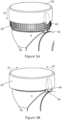
- Figures 5A and 5B shown the fitting of the second valve cap 50.
- a projection 48 on the second valve cap 50 provides a second abutment stop 48 for engagement with the first abutment stop 46 on the valve body 4.
- Recesses are provided on the interior of the second cap 50 to engage with the ridges 26 on the exterior surface first valve cap 20 as the second valve cap 50 is pushed down 52 into place. This provides a key and spline engagement to prevent relative rotation of the first and second valve caps 20,50.
- the second valve cap 50 is assembled onto the first valve cap 20 such that the second abutment stop 48 on the second valve cap 50 abuts the first abutment stop 46 on the valve body, as shown in Figure 5B .
- the ridges provided on the textured interior surface 40 of the valve body 4 correspond with the external ridges 26 on the outer periphery of the cap 20.
- the predefined adjustment steps provided by the ratchet tooth 38 engaging with the textured surface 40 therefore ensure that the second, or outer, valve cap 50 can be fitted in position with the first and second abutment stops 46,48 in contact without changing the rotational position of the first valve cap 20.
- first and second valve caps 20,50 are prevented from rotating relative to one another, and the engagement of the first and second abutment stops 46,48 prevents rotation of the second valve cap 50 in the clockwise direction 42.
- the valve 2 therefore prevents an increase of threshold pressure beyond the desired level, such as 60 cmH 2 O.
- the engagement of the first and second abutment stops 46,48 does not impede rotation of the first and second valve caps 20,50 in the anticlockwise direction 54, so the threshold pressure of the valve 2 can be adjusted to lower than 60 cmH 2 O if required.
- valve caps 20,50 are rotated anticlockwise 54 to the end of the screw thread 32, the valve member 10 will still be clear of the valve seat 6, as shown in Figures 1 and 3 , so the valve 2 can still be set to a minimum threshold pressure of 0 cmH 2 O if required.
- the threshold pressure at the fully open position of the valve 2 will thus always be 0 cmH 2 O, regardless of the spring strength selected.
- the outer/second valve cap 50 clips over the first valve cap 20 and locks these together so that once pushed down 52 into place during assembly, the second valve cap 50 cannot be readily removed from the first valve cap 20.
- Figure 6 shows a cross-section of the arrangement.
- One or more clips 56 are provided around the periphery on the interior surface of the second valve cap 50, and engage underneath the ridges 26 on the outer surface of the first valve cap 20 to secure the caps 20,50 together.
- the valve member 10 can be seen within the valve body 4 in Figure 6 , with the resilient element 8 engaged with the valve seat 6.
- the coil spring 30 is omitted, and the second abutment stop 48 of the second valve cap 50 is obscured behind the first abutment stop 46 on the valve body 4.
- the breathing system of Figure 7 includes a pair of T shaped connectors 58 providing a flow passageway with first and second ends 60,62 and first and second side connectors 64,66. It will be appreciated that a similar arrangement could be provided in a single, more complex, connecter piece if desired.
- the first end 60 is connected to a reservoir bag 68, while the second end 62 is connectable to a patient/user interface device 70, for example a breathing mask.
- the fist side connector 64 is connected to a tube 72, which is in fluid connection with a fresh gas supply, for example an oxygen concentrator or other compressed gas source 74, a ventilator or an anaesthetic/anaesthesia machine.
- the inlet 34 of the APL valve 2 of the invention is connected to the second side connector 66 to provide a pressure release valve.
- the valve member 10 will open and allow excess gas flow to pass through the valve 10 and out of the outlet 36.
Landscapes
- Engineering & Computer Science (AREA)
- General Engineering & Computer Science (AREA)
- Health & Medical Sciences (AREA)
- Mechanical Engineering (AREA)
- Heart & Thoracic Surgery (AREA)
- Pulmonology (AREA)
- Anesthesiology (AREA)
- Biomedical Technology (AREA)
- Emergency Medicine (AREA)
- Hematology (AREA)
- Life Sciences & Earth Sciences (AREA)
- Animal Behavior & Ethology (AREA)
- General Health & Medical Sciences (AREA)
- Public Health (AREA)
- Veterinary Medicine (AREA)
- Safety Valves (AREA)
- Fluid-Driven Valves (AREA)
Applications Claiming Priority (2)
| Application Number | Priority Date | Filing Date | Title |
|---|---|---|---|
| GB1909121.4A GB2585035B (en) | 2019-06-25 | 2019-06-25 | An adjustable valve |
| PCT/EP2020/067950 WO2020260536A1 (en) | 2019-06-25 | 2020-06-25 | An adjustable valve |
Publications (2)
| Publication Number | Publication Date |
|---|---|
| EP3990809A1 EP3990809A1 (en) | 2022-05-04 |
| EP3990809B1 true EP3990809B1 (en) | 2023-05-10 |
Family
ID=67511743
Family Applications (1)
| Application Number | Title | Priority Date | Filing Date |
|---|---|---|---|
| EP20742652.9A Active EP3990809B1 (en) | 2019-06-25 | 2020-06-25 | An adjustable valve |
Country Status (7)
| Country | Link |
|---|---|
| US (1) | US11898646B2 (da) |
| EP (1) | EP3990809B1 (da) |
| AU (1) | AU2020301557B2 (da) |
| DK (1) | DK3990809T3 (da) |
| ES (1) | ES2948910T3 (da) |
| GB (1) | GB2585035B (da) |
| WO (1) | WO2020260536A1 (da) |
Families Citing this family (3)
| Publication number | Priority date | Publication date | Assignee | Title |
|---|---|---|---|---|
| US12472919B2 (en) * | 2020-04-30 | 2025-11-18 | Hitachi Astemo Ueda, Ltd. | Check valve and brake system |
| CN114151598B (zh) * | 2021-10-25 | 2023-11-28 | 浙江新大塑料管件有限公司 | 一种球阀开关调节省力的pe球阀 |
| AU2023235568A1 (en) * | 2022-03-14 | 2024-10-17 | Fisher & Paykel Healthcare Limited | Vent and pressure regulating device |
Family Cites Families (36)
| Publication number | Priority date | Publication date | Assignee | Title |
|---|---|---|---|---|
| US427264A (en) * | 1890-05-06 | And magdalena | ||
| US347213A (en) * | 1886-08-10 | Safety-valve | ||
| US401391A (en) * | 1889-04-16 | Regulating-valve for dental vulcanizers | ||
| US2254209A (en) | 1941-09-02 | Valve | ||
| US1187300A (en) * | 1916-02-02 | 1916-06-13 | George W Girard | Pressure-indicator. |
| US1482517A (en) * | 1923-02-26 | 1924-02-05 | Paul C Swole | Signal valve |
| US1743350A (en) * | 1926-09-13 | 1930-01-14 | Cons Ashcroft Hancock Co | Spring adjustment for valves, etc. |
| US2353306A (en) * | 1939-02-07 | 1944-07-11 | Guy J Henry | Relief valve |
| US2412205A (en) * | 1945-05-12 | 1946-12-10 | John A Cook | Pontoon metering valve and combination |
| US2601563A (en) * | 1948-10-30 | 1952-06-24 | Selwyn Landers Company | Relief valve |
| US2683464A (en) * | 1952-07-24 | 1954-07-13 | Weatherhead Co | Relief valve seal |
| US2908288A (en) * | 1955-04-13 | 1959-10-13 | Crane Co | Calibrated relief valve |
| US3422840A (en) | 1966-01-17 | 1969-01-21 | Grove Valve & Regulator Co | Relief valve with resilient seal means |
| US3796228A (en) * | 1972-08-25 | 1974-03-12 | A Bedo | Relief valve |
| US4103704A (en) * | 1977-02-16 | 1978-08-01 | Eaton Corporation | Safety relief valve |
| US4312376A (en) * | 1980-05-23 | 1982-01-26 | Transamerica Delaval Inc. | Pressure-sustaining valve |
| US4530373A (en) * | 1983-02-22 | 1985-07-23 | Nupro Company | Pressure relief valve |
| DE3531189A1 (de) * | 1985-08-31 | 1987-03-12 | Rheinmetall Gmbh | Ventilanordnung |
| US4790348A (en) * | 1987-08-26 | 1988-12-13 | Nupro Company | Low pressure relief valve |
| FR2685427B1 (fr) * | 1991-12-23 | 1995-04-14 | Sfr Sa Robineterie | Soupape de surete. |
| NL9300862A (nl) * | 1993-05-18 | 1994-12-16 | Flamco Bv | Klep. |
| US5664447A (en) * | 1994-10-03 | 1997-09-09 | Neeley; Rocky E. | Valve lockout |
| AT405675B (de) * | 1996-06-26 | 1999-10-25 | Hygrama Ag | Vorrichtung zur begrenzung der vorspannung einer regelfeder |
| DE19724328C1 (de) * | 1997-06-10 | 1998-10-29 | Mannesmann Sachs Ag | Dämpfventil mit einstellbarer Dämpfkraft |
| US6029766A (en) * | 1997-06-17 | 2000-02-29 | Heidt's Hot Rod Shop, Inc. | Adjustable power steering proportioning valve |
| DE19926867A1 (de) * | 1999-06-12 | 2000-12-14 | Grohe Armaturen Friedrich | Stellvorrichtung |
| US6619308B2 (en) * | 1999-07-09 | 2003-09-16 | I-Flow Corporation | Pressure regulator |
| US6644313B2 (en) * | 2001-02-01 | 2003-11-11 | Fisher & Paykel Healthcare Limited | Breathing assistance apparatus |
| GB2382639B (en) * | 2001-11-30 | 2005-07-20 | Flexicare Medical Ltd | Valves |
| JP4548823B2 (ja) * | 2004-03-31 | 2010-09-22 | サーパス工業株式会社 | 安全弁装置 |
| DE602006019717D1 (de) | 2006-08-08 | 2011-03-03 | Teleflex Medical Europ Ltd | Druckbegrenzungsventil, im Besonderen für medizinisches Gerät zur assistierten Beatmung |
| NL1034284C2 (nl) | 2007-08-24 | 2009-02-25 | Emergency Pulmonary Care B V | Regelbare klep. |
| JP5283530B2 (ja) * | 2009-02-16 | 2013-09-04 | アトムメディカル株式会社 | 人工呼吸器用圧力調節装置およびこのような圧力調節装置を用いた人工呼吸器 |
| JP2014160424A (ja) | 2013-02-20 | 2014-09-04 | Smc Corp | 流量制御装置 |
| JP6224972B2 (ja) * | 2013-09-20 | 2017-11-01 | サーパス工業株式会社 | 安全弁 |
| TR201913173A1 (tr) * | 2019-09-01 | 2021-03-22 | Serdar Plastik Sanayi Ve Ticaret Anonim Sirketi | PRV Basınç Tahliye Valfi |
-
2019
- 2019-06-25 GB GB1909121.4A patent/GB2585035B/en active Active
-
2020
- 2020-06-25 ES ES20742652T patent/ES2948910T3/es active Active
- 2020-06-25 AU AU2020301557A patent/AU2020301557B2/en active Active
- 2020-06-25 EP EP20742652.9A patent/EP3990809B1/en active Active
- 2020-06-25 WO PCT/EP2020/067950 patent/WO2020260536A1/en not_active Ceased
- 2020-06-25 DK DK20742652.9T patent/DK3990809T3/da active
- 2020-06-25 US US17/621,811 patent/US11898646B2/en active Active
Also Published As
| Publication number | Publication date |
|---|---|
| EP3990809A1 (en) | 2022-05-04 |
| AU2020301557B2 (en) | 2022-06-16 |
| GB2585035B (en) | 2023-04-26 |
| US20220260166A1 (en) | 2022-08-18 |
| WO2020260536A1 (en) | 2020-12-30 |
| DK3990809T3 (da) | 2023-07-03 |
| GB2585035A (en) | 2020-12-30 |
| ES2948910T3 (es) | 2023-09-21 |
| US11898646B2 (en) | 2024-02-13 |
| AU2020301557A1 (en) | 2022-02-17 |
| GB201909121D0 (en) | 2019-08-07 |
Similar Documents
| Publication | Publication Date | Title |
|---|---|---|
| AU2020301557B2 (en) | An adjustable valve | |
| US8408209B2 (en) | Pressure controller for artificial respirator and artificial respirator using the same | |
| US20110168180A1 (en) | Adjustable valve | |
| EP1793299B1 (en) | Dual gas pressure regulator for a household appliance | |
| US20170333661A1 (en) | Respiratory therapy apparatus | |
| DE2344881B2 (de) | Pädiatrisches Beatmungsgerät | |
| GB2404721A (en) | Exhalation valve | |
| US4026284A (en) | Pressure relief valve for anesthetic administration | |
| US6681766B1 (en) | Regulator for diving | |
| US6718976B1 (en) | Regulator for diving | |
| EP2805748B1 (de) | Atemmaske mit Notatemventil | |
| US6715488B1 (en) | Regulator for diving | |
| KR102132582B1 (ko) | 공기호흡기용 압력 디멘드 밸브 | |
| CN112805069B (zh) | 按需调节器 | |
| CN115999010B (zh) | 可调泄压阀及其装配方法 | |
| JP5159546B2 (ja) | 人工呼吸器用圧力調節装置およびこのような圧力調節装置を用いた人工呼吸器 | |
| US8360054B2 (en) | Demand valve device for use by diverse and selectively connectable fluidic connector | |
| GB2382639A (en) | An integrated pressure relief and flow control valve | |
| CN111467639B (zh) | 一种直动式医用需求阀 | |
| US6899312B2 (en) | Pressure relief valve for flowing media | |
| US20080099018A1 (en) | Pressure regulator valve for breathing apparatus | |
| GB2406285A (en) | PEEP valve for respiratory circuit | |
| JP2005215942A (ja) | レギュレータ | |
| GB2164571A (en) | Pressure limiting valve assembly | |
| US20250345543A1 (en) | Speaking valve, closure means for a speaking valve, and method |
Legal Events
| Date | Code | Title | Description |
|---|---|---|---|
| STAA | Information on the status of an ep patent application or granted ep patent |
Free format text: STATUS: UNKNOWN |
|
| STAA | Information on the status of an ep patent application or granted ep patent |
Free format text: STATUS: THE INTERNATIONAL PUBLICATION HAS BEEN MADE |
|
| PUAI | Public reference made under article 153(3) epc to a published international application that has entered the european phase |
Free format text: ORIGINAL CODE: 0009012 |
|
| STAA | Information on the status of an ep patent application or granted ep patent |
Free format text: STATUS: REQUEST FOR EXAMINATION WAS MADE |
|
| 17P | Request for examination filed |
Effective date: 20220121 |
|
| AK | Designated contracting states |
Kind code of ref document: A1 Designated state(s): AL AT BE BG CH CY CZ DE DK EE ES FI FR GB GR HR HU IE IS IT LI LT LU LV MC MK MT NL NO PL PT RO RS SE SI SK SM TR |
|
| DAV | Request for validation of the european patent (deleted) | ||
| DAX | Request for extension of the european patent (deleted) | ||
| GRAP | Despatch of communication of intention to grant a patent |
Free format text: ORIGINAL CODE: EPIDOSNIGR1 |
|
| STAA | Information on the status of an ep patent application or granted ep patent |
Free format text: STATUS: GRANT OF PATENT IS INTENDED |
|
| RIC1 | Information provided on ipc code assigned before grant |
Ipc: A61M 16/06 19850101ALI20230103BHEP Ipc: A61M 16/01 19850101ALI20230103BHEP Ipc: A61M 16/00 19680901ALI20230103BHEP Ipc: F16K 35/10 19680901ALI20230103BHEP Ipc: F16K 27/02 19680901ALI20230103BHEP Ipc: A61M 16/20 19850101ALI20230103BHEP Ipc: F16K 1/02 19680901AFI20230103BHEP |
|
| INTG | Intention to grant announced |
Effective date: 20230131 |
|
| GRAS | Grant fee paid |
Free format text: ORIGINAL CODE: EPIDOSNIGR3 |
|
| GRAA | (expected) grant |
Free format text: ORIGINAL CODE: 0009210 |
|
| STAA | Information on the status of an ep patent application or granted ep patent |
Free format text: STATUS: THE PATENT HAS BEEN GRANTED |
|
| AK | Designated contracting states |
Kind code of ref document: B1 Designated state(s): AL AT BE BG CH CY CZ DE DK EE ES FI FR GB GR HR HU IE IS IT LI LT LU LV MC MK MT NL NO PL PT RO RS SE SI SK SM TR |
|
| REG | Reference to a national code |
Ref country code: GB Ref legal event code: FG4D |
|
| REG | Reference to a national code |
Ref country code: AT Ref legal event code: REF Ref document number: 1566963 Country of ref document: AT Kind code of ref document: T Effective date: 20230515 Ref country code: CH Ref legal event code: EP |
|
| REG | Reference to a national code |
Ref country code: DE Ref legal event code: R096 Ref document number: 602020010791 Country of ref document: DE |
|
| REG | Reference to a national code |
Ref country code: IE Ref legal event code: FG4D |
|
| P01 | Opt-out of the competence of the unified patent court (upc) registered |
Effective date: 20230524 |
|
| REG | Reference to a national code |
Ref country code: DK Ref legal event code: T3 Effective date: 20230628 |
|
| REG | Reference to a national code |
Ref country code: NL Ref legal event code: FP |
|
| REG | Reference to a national code |
Ref country code: LT Ref legal event code: MG9D |
|
| REG | Reference to a national code |
Ref country code: ES Ref legal event code: FG2A Ref document number: 2948910 Country of ref document: ES Kind code of ref document: T3 Effective date: 20230921 |
|
| REG | Reference to a national code |
Ref country code: AT Ref legal event code: MK05 Ref document number: 1566963 Country of ref document: AT Kind code of ref document: T Effective date: 20230510 |
|
| PG25 | Lapsed in a contracting state [announced via postgrant information from national office to epo] |
Ref country code: SE Free format text: LAPSE BECAUSE OF FAILURE TO SUBMIT A TRANSLATION OF THE DESCRIPTION OR TO PAY THE FEE WITHIN THE PRESCRIBED TIME-LIMIT Effective date: 20230510 Ref country code: PT Free format text: LAPSE BECAUSE OF FAILURE TO SUBMIT A TRANSLATION OF THE DESCRIPTION OR TO PAY THE FEE WITHIN THE PRESCRIBED TIME-LIMIT Effective date: 20230911 Ref country code: NO Free format text: LAPSE BECAUSE OF FAILURE TO SUBMIT A TRANSLATION OF THE DESCRIPTION OR TO PAY THE FEE WITHIN THE PRESCRIBED TIME-LIMIT Effective date: 20230810 Ref country code: AT Free format text: LAPSE BECAUSE OF FAILURE TO SUBMIT A TRANSLATION OF THE DESCRIPTION OR TO PAY THE FEE WITHIN THE PRESCRIBED TIME-LIMIT Effective date: 20230510 |
|
| PG25 | Lapsed in a contracting state [announced via postgrant information from national office to epo] |
Ref country code: RS Free format text: LAPSE BECAUSE OF FAILURE TO SUBMIT A TRANSLATION OF THE DESCRIPTION OR TO PAY THE FEE WITHIN THE PRESCRIBED TIME-LIMIT Effective date: 20230510 Ref country code: PL Free format text: LAPSE BECAUSE OF FAILURE TO SUBMIT A TRANSLATION OF THE DESCRIPTION OR TO PAY THE FEE WITHIN THE PRESCRIBED TIME-LIMIT Effective date: 20230510 Ref country code: LV Free format text: LAPSE BECAUSE OF FAILURE TO SUBMIT A TRANSLATION OF THE DESCRIPTION OR TO PAY THE FEE WITHIN THE PRESCRIBED TIME-LIMIT Effective date: 20230510 Ref country code: LT Free format text: LAPSE BECAUSE OF FAILURE TO SUBMIT A TRANSLATION OF THE DESCRIPTION OR TO PAY THE FEE WITHIN THE PRESCRIBED TIME-LIMIT Effective date: 20230510 Ref country code: IS Free format text: LAPSE BECAUSE OF FAILURE TO SUBMIT A TRANSLATION OF THE DESCRIPTION OR TO PAY THE FEE WITHIN THE PRESCRIBED TIME-LIMIT Effective date: 20230910 Ref country code: HR Free format text: LAPSE BECAUSE OF FAILURE TO SUBMIT A TRANSLATION OF THE DESCRIPTION OR TO PAY THE FEE WITHIN THE PRESCRIBED TIME-LIMIT Effective date: 20230510 Ref country code: GR Free format text: LAPSE BECAUSE OF FAILURE TO SUBMIT A TRANSLATION OF THE DESCRIPTION OR TO PAY THE FEE WITHIN THE PRESCRIBED TIME-LIMIT Effective date: 20230811 |
|
| PG25 | Lapsed in a contracting state [announced via postgrant information from national office to epo] |
Ref country code: FI Free format text: LAPSE BECAUSE OF FAILURE TO SUBMIT A TRANSLATION OF THE DESCRIPTION OR TO PAY THE FEE WITHIN THE PRESCRIBED TIME-LIMIT Effective date: 20230510 |
|
| PG25 | Lapsed in a contracting state [announced via postgrant information from national office to epo] |
Ref country code: SK Free format text: LAPSE BECAUSE OF FAILURE TO SUBMIT A TRANSLATION OF THE DESCRIPTION OR TO PAY THE FEE WITHIN THE PRESCRIBED TIME-LIMIT Effective date: 20230510 |
|
| PG25 | Lapsed in a contracting state [announced via postgrant information from national office to epo] |
Ref country code: SM Free format text: LAPSE BECAUSE OF FAILURE TO SUBMIT A TRANSLATION OF THE DESCRIPTION OR TO PAY THE FEE WITHIN THE PRESCRIBED TIME-LIMIT Effective date: 20230510 Ref country code: SK Free format text: LAPSE BECAUSE OF FAILURE TO SUBMIT A TRANSLATION OF THE DESCRIPTION OR TO PAY THE FEE WITHIN THE PRESCRIBED TIME-LIMIT Effective date: 20230510 Ref country code: RO Free format text: LAPSE BECAUSE OF FAILURE TO SUBMIT A TRANSLATION OF THE DESCRIPTION OR TO PAY THE FEE WITHIN THE PRESCRIBED TIME-LIMIT Effective date: 20230510 Ref country code: EE Free format text: LAPSE BECAUSE OF FAILURE TO SUBMIT A TRANSLATION OF THE DESCRIPTION OR TO PAY THE FEE WITHIN THE PRESCRIBED TIME-LIMIT Effective date: 20230510 Ref country code: CZ Free format text: LAPSE BECAUSE OF FAILURE TO SUBMIT A TRANSLATION OF THE DESCRIPTION OR TO PAY THE FEE WITHIN THE PRESCRIBED TIME-LIMIT Effective date: 20230510 |
|
| REG | Reference to a national code |
Ref country code: CH Ref legal event code: PL |
|
| REG | Reference to a national code |
Ref country code: DE Ref legal event code: R097 Ref document number: 602020010791 Country of ref document: DE |
|
| REG | Reference to a national code |
Ref country code: BE Ref legal event code: MM Effective date: 20230630 |
|
| PG25 | Lapsed in a contracting state [announced via postgrant information from national office to epo] |
Ref country code: MC Free format text: LAPSE BECAUSE OF FAILURE TO SUBMIT A TRANSLATION OF THE DESCRIPTION OR TO PAY THE FEE WITHIN THE PRESCRIBED TIME-LIMIT Effective date: 20230510 |
|
| PG25 | Lapsed in a contracting state [announced via postgrant information from national office to epo] |
Ref country code: MC Free format text: LAPSE BECAUSE OF FAILURE TO SUBMIT A TRANSLATION OF THE DESCRIPTION OR TO PAY THE FEE WITHIN THE PRESCRIBED TIME-LIMIT Effective date: 20230510 |
|
| PG25 | Lapsed in a contracting state [announced via postgrant information from national office to epo] |
Ref country code: LU Free format text: LAPSE BECAUSE OF NON-PAYMENT OF DUE FEES Effective date: 20230625 |
|
| PLBE | No opposition filed within time limit |
Free format text: ORIGINAL CODE: 0009261 |
|
| STAA | Information on the status of an ep patent application or granted ep patent |
Free format text: STATUS: NO OPPOSITION FILED WITHIN TIME LIMIT |
|
| PG25 | Lapsed in a contracting state [announced via postgrant information from national office to epo] |
Ref country code: LU Free format text: LAPSE BECAUSE OF NON-PAYMENT OF DUE FEES Effective date: 20230625 |
|
| 26N | No opposition filed |
Effective date: 20240213 |
|
| PG25 | Lapsed in a contracting state [announced via postgrant information from national office to epo] |
Ref country code: CH Free format text: LAPSE BECAUSE OF NON-PAYMENT OF DUE FEES Effective date: 20230630 |
|
| PG25 | Lapsed in a contracting state [announced via postgrant information from national office to epo] |
Ref country code: SI Free format text: LAPSE BECAUSE OF FAILURE TO SUBMIT A TRANSLATION OF THE DESCRIPTION OR TO PAY THE FEE WITHIN THE PRESCRIBED TIME-LIMIT Effective date: 20230510 |
|
| PG25 | Lapsed in a contracting state [announced via postgrant information from national office to epo] |
Ref country code: SI Free format text: LAPSE BECAUSE OF FAILURE TO SUBMIT A TRANSLATION OF THE DESCRIPTION OR TO PAY THE FEE WITHIN THE PRESCRIBED TIME-LIMIT Effective date: 20230510 Ref country code: BE Free format text: LAPSE BECAUSE OF NON-PAYMENT OF DUE FEES Effective date: 20230630 |
|
| PG25 | Lapsed in a contracting state [announced via postgrant information from national office to epo] |
Ref country code: BG Free format text: LAPSE BECAUSE OF FAILURE TO SUBMIT A TRANSLATION OF THE DESCRIPTION OR TO PAY THE FEE WITHIN THE PRESCRIBED TIME-LIMIT Effective date: 20230510 |
|
| PG25 | Lapsed in a contracting state [announced via postgrant information from national office to epo] |
Ref country code: BG Free format text: LAPSE BECAUSE OF FAILURE TO SUBMIT A TRANSLATION OF THE DESCRIPTION OR TO PAY THE FEE WITHIN THE PRESCRIBED TIME-LIMIT Effective date: 20230510 |
|
| PGFP | Annual fee paid to national office [announced via postgrant information from national office to epo] |
Ref country code: NL Payment date: 20250515 Year of fee payment: 6 |
|
| PGFP | Annual fee paid to national office [announced via postgrant information from national office to epo] |
Ref country code: DE Payment date: 20250512 Year of fee payment: 6 |
|
| PGFP | Annual fee paid to national office [announced via postgrant information from national office to epo] |
Ref country code: GB Payment date: 20250409 Year of fee payment: 6 Ref country code: DK Payment date: 20250513 Year of fee payment: 6 |
|
| PGFP | Annual fee paid to national office [announced via postgrant information from national office to epo] |
Ref country code: IT Payment date: 20250411 Year of fee payment: 6 |
|
| PGFP | Annual fee paid to national office [announced via postgrant information from national office to epo] |
Ref country code: FR Payment date: 20250409 Year of fee payment: 6 |
|
| PG25 | Lapsed in a contracting state [announced via postgrant information from national office to epo] |
Ref country code: CY Free format text: LAPSE BECAUSE OF FAILURE TO SUBMIT A TRANSLATION OF THE DESCRIPTION OR TO PAY THE FEE WITHIN THE PRESCRIBED TIME-LIMIT; INVALID AB INITIO Effective date: 20200625 |
|
| PGFP | Annual fee paid to national office [announced via postgrant information from national office to epo] |
Ref country code: IE Payment date: 20250409 Year of fee payment: 6 |
|
| PG25 | Lapsed in a contracting state [announced via postgrant information from national office to epo] |
Ref country code: HU Free format text: LAPSE BECAUSE OF FAILURE TO SUBMIT A TRANSLATION OF THE DESCRIPTION OR TO PAY THE FEE WITHIN THE PRESCRIBED TIME-LIMIT; INVALID AB INITIO Effective date: 20200625 |
|
| PGFP | Annual fee paid to national office [announced via postgrant information from national office to epo] |
Ref country code: ES Payment date: 20250708 Year of fee payment: 6 |
|
| PG25 | Lapsed in a contracting state [announced via postgrant information from national office to epo] |
Ref country code: TR Free format text: LAPSE BECAUSE OF FAILURE TO SUBMIT A TRANSLATION OF THE DESCRIPTION OR TO PAY THE FEE WITHIN THE PRESCRIBED TIME-LIMIT Effective date: 20230510 |