EP3990832B1 - Topfträger, gaskochfeld und verfahren zum herstellen eines topfträgers - Google Patents
Topfträger, gaskochfeld und verfahren zum herstellen eines topfträgers Download PDFInfo
- Publication number
- EP3990832B1 EP3990832B1 EP20734518.2A EP20734518A EP3990832B1 EP 3990832 B1 EP3990832 B1 EP 3990832B1 EP 20734518 A EP20734518 A EP 20734518A EP 3990832 B1 EP3990832 B1 EP 3990832B1
- Authority
- EP
- European Patent Office
- Prior art keywords
- gas
- pan support
- outlet openings
- hob
- support
- Prior art date
- Legal status (The legal status is an assumption and is not a legal conclusion. Google has not performed a legal analysis and makes no representation as to the accuracy of the status listed.)
- Active
Links
Images




Classifications
-
- F—MECHANICAL ENGINEERING; LIGHTING; HEATING; WEAPONS; BLASTING
- F24—HEATING; RANGES; VENTILATING
- F24C—DOMESTIC STOVES OR RANGES ; DETAILS OF DOMESTIC STOVES OR RANGES, OF GENERAL APPLICATION
- F24C3/00—Stoves or ranges for gaseous fuels
- F24C3/08—Arrangement or mounting of burners
- F24C3/085—Arrangement or mounting of burners on ranges
-
- F—MECHANICAL ENGINEERING; LIGHTING; HEATING; WEAPONS; BLASTING
- F24—HEATING; RANGES; VENTILATING
- F24C—DOMESTIC STOVES OR RANGES ; DETAILS OF DOMESTIC STOVES OR RANGES, OF GENERAL APPLICATION
- F24C15/00—Details
- F24C15/10—Tops, e.g. hot plates; Rings
- F24C15/107—Pan supports or grates therefor
-
- F—MECHANICAL ENGINEERING; LIGHTING; HEATING; WEAPONS; BLASTING
- F24—HEATING; RANGES; VENTILATING
- F24C—DOMESTIC STOVES OR RANGES ; DETAILS OF DOMESTIC STOVES OR RANGES, OF GENERAL APPLICATION
- F24C15/00—Details
- F24C15/10—Tops, e.g. hot plates; Rings
-
- F—MECHANICAL ENGINEERING; LIGHTING; HEATING; WEAPONS; BLASTING
- F23—COMBUSTION APPARATUS; COMBUSTION PROCESSES
- F23D—BURNERS
- F23D14/00—Burners for combustion of a gas, e.g. of a gas stored under pressure as a liquid
- F23D14/02—Premix gas burners, i.e. in which gaseous fuel is mixed with combustion air upstream of the combustion zone
-
- F—MECHANICAL ENGINEERING; LIGHTING; HEATING; WEAPONS; BLASTING
- F24—HEATING; RANGES; VENTILATING
- F24C—DOMESTIC STOVES OR RANGES ; DETAILS OF DOMESTIC STOVES OR RANGES, OF GENERAL APPLICATION
- F24C3/00—Stoves or ranges for gaseous fuels
- F24C3/12—Arrangement or mounting of control or safety devices
- F24C3/126—Arrangement or mounting of control or safety devices on ranges
-
- F—MECHANICAL ENGINEERING; LIGHTING; HEATING; WEAPONS; BLASTING
- F23—COMBUSTION APPARATUS; COMBUSTION PROCESSES
- F23D—BURNERS
- F23D2900/00—Special features of, or arrangements for burners using fluid fuels or solid fuels suspended in a carrier gas
- F23D2900/14—Special features of gas burners
- F23D2900/14042—Star shaped assembly of burner bars or arms
Definitions
- the present invention relates to a pan support and a gas hob with such a pan support.
- the invention also relates to a method for producing a pan support.
- Gas hobs usually comprise a hob plate with a through hole on which a gas burner is arranged.
- the gas burner has a gas valve for providing fuel gas, whereby the gas valve is usually arranged below the hob plate.
- the fuel gas is mixed with primary air to form a combustible fuel gas-air mixture. This usually takes place in a mixing chamber that is arranged below the hob plate.
- a gas hob can also include a pan support.
- the pan support can be provided as a removable component, for example to make cleaning the gas hob easier.
- the pan support is usually just a support structure that is designed to hold a food container above the gas burner.
- the gas burner usually comprises a burner top that is arranged above the hob plate and has gas burner openings.
- the fuel gas-air mixture is provided at the gas burner openings in order to maintain a flame below the food container to heat it.
- the burner top and the pot support are usually designed as separate components.
- the WO 2019/048970 A1 discloses a pan support for a gas stove with a support structure for a food container, which has a support surface for the food container and a channel for a combustible fuel gas-air mixture, which leads to gas outlet openings,
- the fingers that form the supporting structure and have the gas outlet openings are supported at both ends by a column section or tube section, which makes cleaning the gas hob difficult.
- the support surface is flat and is suitable for pots, pans and the like.
- the WO 2019/008456 A1 discloses a burner top in which self-supporting supports form a support surface for a food container and are provided with gas outlet openings.
- the supports can be moved between different working positions by means of an electric motor in order to be able to adapt to different underside contours of food containers such as pans, pots and also woks.
- an object of the present invention is to provide an improved pot support.
- a pan support for a gas hob which has cantilevered arms, each of which has a support surface for a food container and gas outlet openings for providing a fuel gas-air mixture for forming a flame below the food container.
- a "gas hob” refers in particular to a household appliance with one or more gas cooking zones. Each gas cooking zone has in particular a proposed pan support which can be attached to a cooking zone plate of the gas hob.
- the "supporting surface” is in particular a surface on which a cooking container, such as a pot or wok, rests during cooking.
- a “cantilever arm” is understood to mean in particular an arm or finger in which loads are diverted exclusively to one of the two sides (ends) of the cantilever arm.
- One side is also referred to as the supported side.
- Loads are, for example, loads that are exerted on the arm by the food container resting on the support surface.
- a cantilever arm In an attached state of the pan support in which the pan support is attached to a hob plate of the gas hob, such a cantilever arm can in particular only be connected to the hob plate on the supported side.
- the other side of the cantilever arm can float freely.
- the other side is also referred to as the free side or free end.
- Channel means in particular a cavity which is surrounded along its extension by a solid material of the pot support and is designed to conduct a fluid, in particular the fuel gas-air mixture, along its extension.
- forming a flame is understood to mean in particular the generation and maintenance of the flame by supplying - through the channel - the fuel gas-air mixture, which can be ignited outside the gas outlet openings by an igniter or the like.
- the number of cantilever arms is preferably between three and six, more preferably four or five, and most preferably four.
- gas outlet openings on the cantilever arms By designing the gas outlet openings on the cantilever arms, functional integration can be achieved, as the cantilever arms can support the food container on the one hand and at the same time supply the fuel gas-air mixture to form the flame. In particular, no additional gas burner cover or burner top with gas outlet openings is required.
- each cantilever arm can only have one connection to the hob plate instead of two. This means that the number of connections between the pan support or the cantilever arms and the hob plate can be minimized.
- the gas outlet openings can be arranged next to one another along an extension direction of a respective cantilevered arm.
- the gas outlet openings can particularly preferably be spaced apart from one another at the same distance. Heat can thus be transferred evenly and over a large area to the underside of the food container.
- the cantilever arms each extend radially outward from a central region of the pot support, and a single connecting section for connecting the cantilever arms to a hob plate of the gas hob is formed in the central region.
- the "connecting section” serves in particular on the one hand as a base for supporting the cantilever arms on the hob plate.
- the "connecting section” serves in particular on the other hand to establish a fluid connection between one or more gas valves of the hob plate and one or more channels that lead from respective gas connections of the connecting section to the gas outlet openings.
- the connecting section can be designed as a single connecting section in particular in that, when the pan support is attached, the respective supported sides of the cantilever arms lie flush against one another and thus form a single or common connecting section.
- the connecting section can be designed as a single piece or as a single part.
- the cantilever arms can be rigidly connected to one another or as a single piece, regardless of whether the pan support is attached to the hob plate or not.
- an entire support structure formed from the cantilever arms can only be connected to the hob plate at a single point. This can particularly advantageously improve the accessibility of the hob plate for cleaning and the like.
- the cantilevered arms extend obliquely upwards from the central region.
- the cantilever arms extend radially outwards at an angle upwards. "Upwards” means in particular a direction away from the hob plate when the pan support is attached to the hob plate. In other words, a distance between the respective cantilever arm and the hob plate can increase outwards when the pan support is attached.
- An angle of inclination of the arms extending obliquely upwards is preferably between 10° and 20°, particularly preferably between 10° and 15° and most particularly preferably 13°.
- the support surface for the food container is arranged radially outside the plurality of gas outlet openings.
- a central flame can advantageously be provided under a bottom side of the cooking container.
- the radially inner gas outlet openings are also arranged at a lower level than the radially outer support surface. This means that the distance between the gas outlet openings and the underside of the food container placed on the support surface can be increased and the underside of the food container can therefore be better positioned at a point of greatest flame heat.
- each cantilevered arm has a protrusion at its free end.
- the support surface for the food container is formed by a surface of the protrusion.
- protrusion is to be understood in particular as a protrusion upwards, where “up” refers to a direction which, when the pan support is attached, points away from the hob plate along a surface normal of the hob plate.
- a distance between a bottom of the food container placed on the support surface and the gas outlet openings of the cantilevered arm can be further increased and thereby the bottom of the food container can be placed even more favorably at a hottest point of the flames formed at the gas outlet openings.
- the support surface in particular the support surface formed by the surface of the protrusion, has a horizontal section and an inclined section.
- “Horizontal” refers in particular to a direction that runs parallel to the hob plate when the pan support is attached.
- “Slanted” refers in particular to a direction that runs obliquely to the hob plate when the pan support is attached.
- the oblique section of the surface of the protrusion can run more steeply upwards than a surface of the cantilever arm in the area between the central area and the protrusion.
- An inclination angle of the oblique section is preferably between 20° and 30° and particularly preferably 25°.
- a pot or a pan can advantageously be placed on the horizontal sections of the support surfaces of the cantilever arms.
- a wok can advantageously be placed between the slanted sections of the support surfaces of the cantilever arms.
- the pot, the pan and the wok are possible examples of the cooking container.
- the pot support can be used flexibly with different types of cooking containers.
- the support surface which is formed in particular by the surface of the protrusion, further comprises a curved section between the horizontal and the oblique section.
- the curved section is in particular a section in which an inclination of the support surface continuously changes from the horizontal to the oblique direction.
- the curved section advantageously allows the flexible placement of woks of different sizes and/or woks with different diameters or radii of curvature between the curved sections of the support surfaces of the cantilever arms.
- a respective cantilevered arm has two arm sections spaced apart from one another in the circumferential direction by an intermediate space.
- the gas outlet openings are arranged on the two arm sections and each comprise internal gas outlet openings open to the intermediate space and external gas outlet openings open to the outside.
- the "circumferential direction” refers in particular to a circumferential direction with respect to the central region of the pot support or, in other words, a transverse direction of the cantilever arm which perpendicularly intersects a central axis of the cantilever arm extending in the radial direction.
- the two arm sections of the cantilever arm are axially symmetrical to a radial central axis of the cantilever arm.
- the intermediate space can in particular be formed in at least one radial section of the cantilever arm.
- the intermediate space can extend in the radial direction from the central region to the protrusion.
- the gap can also extend over the entire radial extent of the cantilever arm to its free end.
- the gap can be open to the outside in the radial direction of the cantilever arm.
- two arms or fingers running parallel or essentially parallel to one another with a gap between them are referred to as two arm sections of one and the same cantilever arm.
- the total number of gas outlet openings of the cantilever arm can advantageously be increased and thus the combustion power provided by the cantilever arm can be increased.
- the inner gas outlet openings are connected to a first channel and the outer gas outlet openings are connected to a second channel, wherein the first channels are connected to a first gas connection and the second channels are connected to a second gas connection of the connecting section.
- a respective gas connection of the connecting section is in particular designed to receive gas from a respective corresponding gas valve provided below the hob plate when the pan support is attached.
- two gas valves can be provided on or below the hob plate for the gas hob formed by the pan support.
- the pan support can therefore enable the corresponding gas hob to be operated at different power levels.
- the flame can be provided either only at the external, only at the internal, or both at the external and internal gas outlet openings of the cantilevered arms of the pan support.
- two adjacent cantilever arms form a corner with each other.
- the spaces between the adjacent cantilever arms and the corner are connected by an ignition channel.
- adjacent cantilever arms we mean cantilever arms that extend in different radial directions and are adjacent to each other in the circumferential direction.
- an igniter can be arranged in the corner.
- the igniter can, for example, be an electrically operated device that generates a spark when activated.
- the ignition channel advantageously allows the ignition of the external and internal gas outlet openings of the circumferentially adjacent cantilever arms using just one single igniter. For example, when the igniter is activated, the fuel gas-air mixture flowing out of the external gas outlet openings that are arranged on the sides of the adjacent cantilever arms connected by the corner can be ignited. The burning fuel gas-air mixture can then spread through the ignition channel to the spaces between the adjacent cantilevered arms and cause ignition of the fuel gas-air mixture flowing out of the internal gas outlet openings.
- the proposed structure with ignition channels thus advantageously enables easy ignition of the fuel gas-air mixture provided by the pot carrier with the cantilevered arms, which have both external and internal gas outlet openings.
- the cantilever arms are designed as a one-piece or one-piece support structure.
- “Integral” means that the support structure of the pot carrier and/or the pot carrier is made from a base material or raw material, in particular preformed.
- the support structure and/or the pot carrier is manufactured using 3D printing. With a support structure made from a single material, complex joining steps are not required during production. In addition, a high-quality appearance of the pot carrier can be provided.
- the gas hob comprises in particular one or more gas cooking zones, wherein each gas cooking zone is formed by a pan support attached to the hob plate.
- the hob plate for the respective gas hob can have an opening into which the connecting section of the corresponding pan support is inserted.
- a gas valve for providing fuel gas for the gas hob can be provided below the hob plate, and a channel leading from the gas outlet openings to the connecting section can be provided in the pan support.
- the gas hob can be set up in such a way that, during operation, a fuel gas-air mixture of primary air and fuel gas provided by the gas valve is guided via the channel to the gas outlet openings.
- the respective pot support is detachably connected to the hob plate.
- the respective pot support can be removable.
- the detachable connection of the pan support to the hob plate advantageously makes it easier to clean the hob plate and the pan supports.
- the risk of the cantilever arms causing collisions, getting caught, cables getting tangled, etc. can be reduced by removing the pan supports and storing them away.
- the detachable connection is a screw connection which can be released by turning the pot support relative to the hob plate.
- the screw connection can enable the pan support to be securely anchored in the hob plate.
- the cantilevered arms can provide sufficient leverage when unscrewing the pan support, allowing the user to easily unscrew the pan support despite the pan support being securely anchored.
- a method for operating a gas hob is also proposed, in which a fuel gas-air mixture is guided to gas outlet openings at a respective gas hob through a channel integrated in a pan support.
- the pan support is designed in particular as described above and below.
- a method for producing a pot carrier according to the invention is proposed, wherein the pot carrier is produced by means of 3D printing, in particular selective laser melting.
- the channel can be provided within the pot support during 3D printing. Furthermore, it is possible to take into account individual customer requests that cannot be produced using conventional methods (for large quantities) when manufacturing such pot supports.
- Fig.1 shows schematically a gas cooking area 1 with a pot support 2 according to a first embodiment
- Fig.2 shows schematically a gas hob 4 with two gas cooking zones 1 in a section II-II from Fig.1
- the first embodiment is based on Fig. 1 and Fig. 2 described.
- the gas hob 4 is an example of a household appliance and can be built into a piece of furniture 3, such as a base cabinet, for example.
- the gas hob 4 has a hob plate 8 with two gas hobs 1.
- the hob plate 8 can be a steel sheet, a glass plate or a glass ceramic plate, for example.
- Each gas hob 1 has a pan support 2 according to the first embodiment.
- Each pan support 2 of the gas hob 4 has four cantilever arms 5.
- Each cantilever arm 5 has a number of gas outlet openings 6 and a support surface 7 for a (in Fig. 1 and 2 not shown) cooking container.
- the pan supports 2 are attached to a cooking plate 8 of the gas cooking surface 4.
- the respective pot support 2 is designed to support a food container placed on the support surfaces 7 (in Fig. 1 and 2 not shown).
- the respective pot support 2 is also designed to form a flame underneath the food container.
- a fuel gas-air mixture can be provided at the gas outlet openings 6 of the cantilever arms 5, which can in particular be ignited to provide the flame.
- the ignition can be done manually by a user or automatically by a (in Fig. 1 and 2 not shown) igniter.
- Each gas cooking zone 1 further comprises a control element 9.
- the control element 9 is designed to control at least one gas valve or Gas control valve (not shown) to control the flow of fuel gas-air mixture supplied to the respective pot carrier 2 can be selectively switched on, switched off and, in particular, continuously switched on.
- the gas control valves can also be designed to regulate the flow of fuel gas-air mixture supplied to the respective pot carrier 2 in stages. This means that the gas control valves can be designed as stepped gas control valves or as so-called step valves.
- a respective cantilever arm 5 is connected to the hob plate 8 exclusively at a supported side thereof and is accordingly supported by the hob plate 8.
- the supported sides of all cantilever arms 5 of a respective drip tray 1 are located in a central region 10 of the pot tray 1.
- the cantilever arms 5 extend radially outwards from the central region 10 of the pot tray 2.
- a single connecting section 11 is formed for connecting the cantilever arms 5 to the hob plate 8 of the gas hob 4.
- the connecting section 11 thus serves as a single base or foot which supports the entire pot tray 2.
- Fig.3 shows a pot support 2 mounted on a hob plate 8 according to a second embodiment and a pot 12 placed thereon.
- the cantilever arms 5 extend radially outwards from the central region 10 at an angle upwards 13, ie away from the hob plate 8.
- the gas outlet openings 6 are formed in a radially inner section of the respective cantilever arm 5.
- the respective cantilever arm 5 has a protrusion 14 which protrudes in an upward direction 13.
- the respective protrusion 14 has a surface which serves as a support surface 7 for the food container 12.
- the radially outer section of the respective cantilever arm 5 with the support surface 7 is arranged further up than the radially inner Section with the gas outlet openings 6.
- a distance between the bottom of the pot 12 and the gas outlet openings 6 is larger than in the Fig.1 shown horizontally extending cantilever arm 5, and the flames at the gas outlet openings 6 can be provided centrally under the bottom of the pot 12. This can ensure an efficient energy transfer to a content of the pot 12.
- the support surface 7 has in particular a horizontal section 15 and an inclined section 16.
- the horizontal section 15 runs parallel to the hob plate 8.
- the inclined section 16 points inwards with respect to the pan support 2, i.e. it is inclined in the direction of the central section 10.
- the pot 12 can be placed stably on the horizontal sections 15 of the support surfaces 7.
- Fig.4 shows the pot support 2 from Fig.3 with a wok placed on top.
- the Wok 19 has a rounded bottom.
- the Wok 19 is therefore, unlike the Pot 12 in Fig.3 , is not placed on the horizontal sections 15 of the support surfaces 7, but is inserted between the inclined sections 16 of the support surfaces 7.
- the pot support 2 from Fig. 3, 4 is inserted with its connecting section 11 into an opening 17 of the hob plate.
- the connection between the pot support 2 and the hob plate 8 is detachable.
- the detachable connection between the connecting section 11 and the opening 17 of the hob plate 8 can be a screw connection.
- a sealing mechanism (not shown) can be provided. When the pan support 2 is unscrewed or removed from the hob plate 8, this can ensure that the opening 17 of the hob plate 8 is sealed liquid-, gas- and dust-tight.
- Fig.5 shows a perspective view of a pot carrier 2 according to a third embodiment.
- the pot support 2 comprises, for example, four cantilever arms 5, one of which is described below as an example.
- the cantilevered arm 5 has two arm sections 21, 22 spaced apart in the circumferential direction 20 in a radial region in which the gas outlet openings 6 are formed.
- An intermediate space 23 is formed between the two arm sections 21, 22.
- Each of the arm sections 21, 22 has internal gas outlet openings 24 that face the intermediate space 23, and external gas outlet openings 25 that face outwards.
- the intermediate space 23 of the cantilevered arm 5 extends in the radial direction from the central region 10 of the pot support 22 to the radially inner side of the protrusion 14.
- the support surface 7 additionally has a curved section 26 between the horizontal section 15 and the inclined section 16.
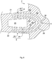
- Fig.6 illustrates a configuration for supplying the fuel gas-air mixture to the pot carrier 2 from Fig.5 .
- Fig.6 shows a schematic horizontal section through the pot support 2 from Fig.5 .
- the inner gas outlet openings 24 of the two arm sections 21, 22 are connected to a respective first channel 27.
- the outer gas outlet openings 25 are connected to a respective second channel 28.
- the first two channels 27 are connected to a first gas connection 29, which is Fig.6 is only shown schematically and at the (in Fig.6 not shown) underside of the connecting section 11 in the central region 10 of the pot support 2.
- the two second channels 28 are connected to a second gas connection 30, which is also arranged on the underside of the connecting section 11.
- the pot support 2 thus arranged can be attached to a corresponding hob plate 8 ( Fig. 1, 2 ) in which for each gas hob 1 ( Fig.2 ) two corresponding gas valves (not shown) are provided.
- the controls 9 may be designed to allow separate activation or deactivation of each of the both gas valves of the gas hob 1 ( Fig.2 ).
- a fuel gas supply through the channels 27 to the internal gas outlet openings 24 and a fuel gas supply through the channels 28 to the external gas outlet openings 25 can be switched on and off independently of one another.
- the pot support 2 of the present embodiment thus allows a demand-based regulation of the combustion power of the gas hob 1 ( Fig.2 ), in that a flame can be provided either only at the internal gas outlet openings 24, only at the external gas outlet openings 25, or at both the internal 24 and the external gas outlet openings 25, as required.
- Fig. 7a-7d illustrate an ignition process in the pot carrier 2 from the Fig.5 , 6 .
- Fig. 7a-7d schematic horizontal sections through the pot support 2.
- two respective cantilever arms 5a-5d of the pot carrier 2 which are adjacent in the circumferential direction 20, form a respective corner 31a-31d.
- a respective ignition channel 32a-32d is formed in the interior of the pot carrier 2, which connects the intermediate spaces 23 of two adjacent cantilever arms 5a-d and the corner 31a-d formed between the two adjacent cantilever arms 5a-d.
- An electrically operable igniter 33a, 33c is arranged in two of the four corners 31a, 31c.
- the fuel gas-air mixture is supplied to both gas connections 29, 30 of the connecting section 11.
- the igniters 33a, 33c are then activated.
- a spark is generated by means of an electric current using the igniters 33a, 33c.
- the spark ignites the fuel gas-air mixture that flows out of those of the external gas outlet openings 25 that are adjacent to one of the corners 33a, 33c.
- flames 34 are provided at those external gas outlet openings 25 that face the corners 33a, 33c, as shown in Fig. 7b is shown.
- the burning fuel gas-air mixture can now flow through the ignition channels 32a, 32c into all four spaces 23. As a result, the fuel gas-air mixture flowing out of the internal gas outlet openings 24 is ignited. From the spaces 23, the burning fuel gas-air mixture can flow further through the ignition channels 32b, 32d into the corners 31b and 31d and there ignite the fuel gas-air mixture flowing out of the external gas outlet openings 25 facing these corners 31b, 31d.
- corresponding flames 34 are provided at all internal 24 and external gas outlet openings 25.
- a low combustion output is required, for example because a small cooking container 12, 19 ( Fig. 3, 4 ) on the support surfaces 7 ( Fig. 3, 4 , 5 ) is placed.
- a user can, as determined by Fig. 7a-c described, the control element 9 ( Fig.2 ) to switch off the gas supply to one of the two gas connections 29, 30.
- Fig. 7d shows a case in which the gas supply to the gas connection 30 has been switched off, which is connected via the second channels 28 to the external gas outlet openings 25. As in Fig. 7d As can be seen, corresponding flames 34 are now only provided at the internal gas outlet openings 24.
- the pot support 2 thus allows flexible regulation of the burning power as required.
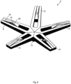
- Fig.8 shows a pot carrier 2 according to a fourth embodiment.
- the pot carrier 2 from Fig.8 has five instead of four cantilever arms 5.
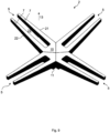
- Fig.9 shows a pot carrier 2 according to an embodiment that is not part of the invention.
- the intermediate space 23 extends from the central region 10 over the entire radial extent of the cantilevered arm 5. Accordingly, the arm sections 21, 22 also extend over the entire radial extent of the cantilevered arm 5.
- the intermediate space 23 is open radially outwards.
- the respective cantilever arm 5 has no protrusion (14 in Fig.5 , 8th ). Rather, a support surface 7 is formed by upwardly facing surfaces 13 of the arm sections 21, 22
- the pot carrier made of Fig.9 is therefore especially suitable for a Wok 19 ( Fig.4 ) suitable.
- the pot support 2 according to the embodiments from the Fig. 1 to 9 is produced, for example, by means of 3D printing, in particular selective laser melting. It is possible to produce the cantilevered arms 5 and/or the connecting section 11 as a one-piece component, in particular with first and second channels 27, 28 provided therein and/or ignition channels 32 provided therein and/or gas outlet openings 6, 24, 25 provided therein.
- the pot carrier 2 is made of a metal, or the pot carrier has a metal.
- pot support 2 it is not necessary to form the pot support 2 in one piece. It is also conceivable to form the pot support 2 as a set of separate cantilever arms 5, which can be separately inserted into an opening 17 of the hob plate 8, wherein the single connecting section 11 results from the fact that the supported ends of the cantilever arms 5 abut one another when the cantilever arms 5 are inserted and thus form a common connecting section 11.
- a respective gas connection or respective gas connections 29, 30 can be formed separately in each supported end of each cantilever arm 5.
Landscapes
- Engineering & Computer Science (AREA)
- Chemical & Material Sciences (AREA)
- Combustion & Propulsion (AREA)
- Mechanical Engineering (AREA)
- General Engineering & Computer Science (AREA)
- Cookers (AREA)
Description
- Die vorliegende Erfindung betrifft einen Topfträger und ein Gaskochfeld mit einem derartigen Topfträger. Außerdem betrifft die Erfindung ein Verfahren zum Herstellen eines Topfträgers.
- Gaskochstellen umfassen in der Regel eine Kochfeldplatte mit einem Durchgangsloch, an dem ein Gasbrenner angeordnet ist. Der Gasbrenner hat ein Gasventil zum Bereitstellen von Brenngas, wobei das Gasventil in der Regel unterhalb der Kochfeldplatte angeordnet ist. Dabei wird das Brenngas mit Primärluft zu einem brennbaren Brenngas-Luft-Gemisch vermischt. Dies erfolgt in der Regel in einer Mischkammer, die unterhalb der Kochfeldplatte angeordnet ist.
- Außerdem kann eine Gaskochstelle einen Topfträger umfassen. Dabei kann der Topfträger als abnehmbares Bauteil vorgesehen sein, um beispielsweise eine Reinigung der Gaskochstelle zu vereinfachen. Der Topfträger ist in der Regel lediglich eine Tragstruktur, die dazu eingerichtet ist, einen Gargutbehälter oberhalb des Gasbrenners zu halten.
- Der Gasbrenner umfasst üblicherweise ein Brenneroberteil, das oberhalb der Kochfeldplatte angeordnet ist und Gasbrenneröffnungen aufweist. An den Gasbrenneröffnungen wird das Brenngasluftgemisch bereitgestellt, um eine Flamme unterhalb des Gargutbehälters zum Erwärmen desselben aufrechtzuerhalten. In der Regel sind das Brenneroberteil und der Topfträger als separate Bauteile ausgebildet.
- Beispiele aus dem Stand der Technik, bei denen das Brenneroberteil und der Topfträger als separate Bauteile ausgebildet, sind in der
WO 2013/017986 A2 undEP 1 469 256 A2 offenbart. Außerdem offenbart dieUS 3,626,923 einen Gasbrenner für einen Grill in Form einer Acht, auf den ein Grillgitter aufgesetzt werden kann. - Die
WO 2019/048970 A1 offenbart einen Topfträger für einen Gasherd mit einer Tragstruktur für einen Gargutbehälter, die eine Auflagefläche für den Gargutbehälter und einen Kanal für ein brennbares Brenngasluftgemisch, welcher zu Gasaustrittsöffnungen führt, aufweist. Allerdings sind die Finger, die die Tragstruktur bilden und die Gasaustrittsöffnungen aufweisen, an ihren beiden Enden durch einen Säulenabschnitt bzw. Rohrabschnitt unterstützt, was eine Reinigung des Gaskochfelds erschwert. Die Auflagefläche ist eben ausgebildet und eignet sich für Töpfe, Pfannen und dergleichen. - Die
WO 2019/008456 A1 offenbart ein Brenneroberteil, bei dem freitragende Träger eine Auflagefläche für einen Gargutbehälter bilden und mit Gasaustrittsöffnungen versehen sind. Die Träger sind mittels eines elektrischen Motors zwischen unterschiedlichen Arbeitspositionen verfahrbar, um an unterschiedliche Unterseitenkonturen von Gargutbehältern, wie Pfannen, Töpfen, aber auch Woks anpassbar zu sein. - Vor diesem Hintergrund besteht eine Aufgabe der vorliegenden Erfindung darin, einen verbesserten Topfträger bereitzustellen.
- Demgemäß wird ein Topfträger für ein Gaskochfeld vorgeschlagen, der freitragende Arme aufweist, die jeweils eine Auflagefläche für einen Gargutbehälter und Gasaustrittsöffnungen zum Bereitstellen eines Brenngas-Luft-Gemisches zum Bilden einer Flamme unterhalb des Gargutbehälters aufweisen.
- Ein "Gaskochfeld" bezeichnet insbesondere ein Haushaltsgerät mit einer oder mehreren Gaskochstellen. Eine jeweilige Gaskochstelle weist insbesondere einen vorgeschlagenen Topfträger auf, der an einer Kochfeldplatte des Gaskochfelds angebracht sein kann.
- Die "Auflagefläche" ist insbesondere eine Fläche, auf der beim Kochen ein Gargutbehälter, wie etwa ein Topf oder Wok, aufliegt.
- Unter einem "freitragenden Arm" ist insbesondere ein Arm bzw. Finger zu verstehen, bei dem aufliegende Lasten ausschließlich zu einer der zwei Seiten (Enden) des freitragenden Arms hin abgeleitet werden. Die eine Seite wird auch als abgestützte Seite bezeichnet. Mit Lasten sind beispielsweise Lasten gemeint, die von dem auf der Auflagefläche aufliegenden Gargutbehälter auf den Arm ausgeübt werden. In einem angebrachten Zustand des Topfträgers, in dem der Topfträger auf einer Kochfeldplatte des Gaskochfelds angebracht ist, kann insbesondere ein derartiger freitragender Arm nur an der abgestützten Seite mit der Kochfeldplatte verbunden sein. Die andere Seite des freitragenden Arms kann hierbei frei schweben. Die andere Seite wird auch als freie Seite bzw. freies Ende bezeichnet.
- Es sei angemerkt, dass im Innern des freitragenden Arms ein Kanal bereitgestellt sein kann, der zu den Gasaustrittsöffnungen führt. "Kanal" meint insbesondere einen Hohlraum, der entlang seiner Erstreckung von einem Vollmaterial des Topfträgers umgeben ist und dazu eingerichtet ist, entlang seiner Erstreckung ein Fluid, insbesondere das Brenngas-Luft-Gemisch, zu leiten.
- Unter "Bilden einer Flamme" ist insbesondere das Erzeugen und Aufrechterhalten der Flamme durch Zuleiten - durch den Kanal - des Brenngas-Luft-Gemischs zu verstehen, welches außerhalb der Gasaustrittsöffnungen von einem Zünder oder dergleichen entzündet werden kann.
- Die Anzahl der freitragenden Arme beträgt bevorzugt zwischen drei und sechs, besonders bevorzugt vier oder fünf, und ganz besonders bevorzugt vier.
- Mit "unterhalb des Gargutbehälters" ist insbesondere gemeint "zwischen Gargutbehälter und Kochfeldplatte, wenn der Topfträger auf der Kochfeldplatte angebracht ist".
- Indem die Gasaustrittsöffnungen an den freitragenden Armen ausgebildet sind, kann eine Funktionsintegration verwirklicht werden, da die freitragenden Arme einerseits den Gargutbehälter tragen und zeitgleich das Brenngas-Luft-Gemisch zum Bilden der Flamme zuführen können. Insbesondere ist keine zusätzliche Gasbrennerabdeckung oder ein Brenneroberteil mit Gasaustrittsöffnungen erforderlich.
- Weiterhin kann - im Vergleich zur Verwendung eines auf beiden Seiten abgestützten Topfträgerelements - bei einem jeweiligen freitragenden Arm statt zweier nur eine Verbindung mit der Kochfeldplatte vorgesehen sein. Somit kann die Anzahl der Verbindungen zwischen dem Topfträger bzw. den freitragenden Armen und der Kochfeldplatte minimiert werden.
- Dadurch kann ein individuelles und hochwertiges Design des Topfträgers und eines Gaskochfelds breitgestellt werden. Im Speziellen kann die Zugänglichkeit der Kochfeldplatte im Bereich unterhalb der freitragenden Arme zum Wischen und dergleichen verbessert sein. Somit kann sich eine vereinfachte Reinigung eines mit dem vorgeschlagenen Topfträger ausgestatteten Gaskochfelds ergeben.
- Insbesondere können die Gasaustrittsöffnungen entlang einer Erstreckungsrichtung eines jeweiligen freitragenden Arms nebeneinander angeordnet sein. Besonders bevorzugt können die Gasaustrittsöffnungen mit einem gleichen Abstand voneinander beabstandet sein. Somit kann Wärme gleichmäßig und großflächig zu einer Unterseite des Gargutbehälters übertragen werden.
- Gemäß einer Ausführungsform verlaufen die freitragenden Arme von einem zentralen Bereich des Topfträgers jeweils radial nach außen, und in dem zentralen Bereich ist ein einziger Verbindungsabschnitt zum Verbinden der freitragenden Arme mit einer Kochfeldplatte des Gaskochfelds ausgebildet.
- Der "zentrale Bereich" kann insbesondere ein Bereich um eine Mittelachse des Topfträgers sein. Das heißt, die freitragenden Arme können insbesondere rings um eine Mittelachse des Topfträgers herum angeordnet sein und von der Mittelachse aus radial nach außen verlaufen.
- Der "Verbindungsabschnitt" dient insbesondere einerseits als Sockel zum Abstützen der freitragenden Arme auf der Kochfeldplatte. Der "Verbindungsabschnitt" dient insbesondere andererseits zum Herstellen einer Fluidverbindung zwischen einem oder mehreren Gasventilen der Kochfeldplatte und einem oder mehreren Kanälen, die von jeweiligen Gasanschlüssen des Verbindungsabschnitts zu den Gasaustrittsöffnungen führen.
- Der Verbindungsabschnitt kann insbesondere dadurch als ein einziger Verbindungsabschnitt ausgebildet sein, dass im angebrachten Zustand des Topfträgers die jeweiligen abgestützten Seiten der freitragenden Arme bündig aneinander anliegen und dadurch einen einzigen bzw. gemeinsamen Verbindungsabschnitt ausbilden. Alternativ hierzu kann der Verbindungsabschnitt materialeinstückig oder einteilig ausgebildet sein. Hierbei können die freitragenden Arme insbesondere unabhängig davon, ob der Topfträger an der Kochfeldplatte angebracht ist oder nicht, starr miteinander verbunden oder materialeinstückig miteinander sein.
- Demgemäß kann im angebrachten Zustand des Topfträgers eine gesamte aus den freitragenden Armen gebildete Tragstruktur nur an einer einzigen Stelle mit der Kochfeldplatte verbunden sein. Somit kann die Zugänglichkeit der Kochfeldplatte zum Reinigen und dergleichen besonders vorteilhaft verbessert sein.
- Gemäß einer weiteren Ausführungsform verlaufen die freitragenden Arme von dem zentralen Bereich aus schräg nach oben.
- Insbesondere verlaufen die freitragenden Arme in ihrem radialen Verlauf nach außen schräg nach oben. "Nach oben" meint insbesondere eine Richtung von der Kochfeldplatte weg, wenn der Topfträger auf der Kochfeldplatte angebracht ist. Anders ausgedrückt kann sich ein Abstand zwischen dem jeweiligen freitragenden Arm und der Kochfeldplatte im angebrachten Zustand des Topfträgers nach außen hin erhöhen.
- Somit kann eine Zugänglichkeit der Kochfeldplatte im Bereich des Topfträgers im angebrachten Zustand des Topfträgers weiter verbessert werden. Ferner kann die Belüftung des Bereichs unter dem Topfträger verbessert und dadurch das Brennverhalten der Flamme verbessert werden, wenn ein Gargutbehälter auf dem Topfträger platziert ist.
- Ein Neigungswinkel der schräg nach oben verlaufenden Arme beträgt bevorzugt zwischen 10° und 20°, besonders bevorzugt zwischen 10° und 15° und ganz besonders bevorzugt 13°.
- Gemäß einer weiteren Ausführungsform ist bei einem jeweiligen freitragenden Arm die Auflagefläche für den Gargutbehälter radial außerhalb der Vielzahl von Gasaustrittsöffnungen angeordnet.
- Somit kann vorteilhafterweise eine mittige bzw. zentrale Flamme unter einer Unterseite des Gargutbehälters bereitgestellt werden.
- Wenn insbesondere der jeweilige freitragende Arm in seinem radialen Verlauf nach außen schräg nach oben verläuft, sind zudem die radial innen liegenden Gasaustrittsöffnungen auf einem tieferen Niveau angeordnet als die radial außen liegende Auflagefläche. Somit kann ein Abstand zwischen den Gasaustrittsöffnungen und der Unterseite des auf der Auflagefläche platzierten Gargutbehälter erhöht werden und dadurch vorteilhafterweise die Unterseite des Gargutbehälters besser an einem Punkt größter Hitze der Flamme platziert werden.
- Bei dem vorgeschlagenen Topfträger weist ein jeweiliger freitragender Arm an seinem freien Ende eine Vorwölbung auf. Hierbei ist die Auflagefläche für den Gargutbehälter durch eine Oberfläche der Vorwölbung ausgebildet.
- Unter "Vorwölbung" ist insbesondere eine Vorwölbung nach oben zu verstehen, wobei "oben" eine Richtung bezeichnet, die bei angebrachtem Zustand des Topfträgers entlang einer Flächennormale der Kochfeldplatte von der Kochfeldplatte weg weist.
- Indem die Auflagefläche durch eine Oberfläche der nach oben weisenden Vorwölbung ausgebildet ist, kann ein Abstand zwischen einer Unterseite des auf der Auflagefläche platzierten Gargutbehälters und den Gasaustrittsöffnungen des freitragenden Arms weiter erhöht und dadurch die Unterseite des Gargutbehälters noch günstiger an einem heißesten Punkt der bei den Gasaustrittsöffnungen gebildeten Flammen platziert werden.
- Bei dem vorgeschlagenen Topfträger weist die Auflagefläche, insbesondere die durch die Oberfläche der Vorwölbung ausgebildete Auflagefläche, einen horizontalen Abschnitt und einen schrägen Abschnitt auf.
- "Horizontal" bezeichnet insbesondere eine Richtung, die im angebrachten Zustand des Topfträgers parallel zu der Kochfeldplatte verläuft. "Schräg" bezeichnet insbesondere eine Richtung, die im angebrachten Zustand des Topfträgers schräg zu der Kochfeldplatte verläuft. Insbesondere kann der schräge Abschnitt der Oberfläche der Vorwölbung steiler nach oben verlaufen als eine Oberfläche des freitragenden Arms im Bereich zwischen dem zentralen Bereich und der Vorwölbung.
- Ein Neigungswinkel des schrägen Abschnitts beträgt bevorzugt zwischen 20° und 30° und besonders bevorzugt 25°.
- Auf den horizontalen Abschnitten der Auflageflächen der freitragenden Arme kann vorteilhafterweise ein Topf oder eine Pfanne platziert werden. Zwischen den schrägen Abschnitten der Auflageflächen der freitragenden Arme kann vorteilhafte ein Wok eingesetzt werden. Der Topf, die Pfanne und der Wok sind mögliche Beispiele für den Gargutbehälter.
- Somit kann der Topfträger vorteilhafterweise flexibel mit verschiedenen Arten von Gargutbehältern benutzt werden.
- Gemäß einer weiteren Ausführungsform weist die Auflagefläche, welche insbesondere durch die Oberfläche der Vorwölbung ausgebildet ist, zwischen dem horizontalen und dem schrägen Abschnitt ferner einen gebogenen Abschnitt auf.
- Der gebogene Abschnitt ist insbesondere ein Abschnitt, in dem eine Neigung der Auflagefläche kontinuierlich von der horizontalen in die schräge Richtung übergeht.
- Der gebogene Abschnitt ermöglicht vorteilhafterweise das flexible Platzieren von unterschiedlich großen Woks und/oder Woks mit unterschiedlichen Durchmessern bzw. Krümmungsradien zwischen den gebogenen Abschnitten der Auflageflächen der freitragenden Arme.
- Gemäß einer weiteren Ausführungsform weist ein jeweiliger freitragender Arm zwei in Umfangsrichtung durch einen Zwischenraum voneinander beabstandete Armabschnitte auf. Hierbei sind die Gasaustrittsöffnungen an den beiden Armabschnitten angeordnet und umfassen jeweils zu dem Zwischenraum offene innenliegende Gasaustrittsöffnungen und nach außen offene außenliegende Gasaustrittsöffnungen.
- Die "Umfangsrichtung" bezeichnet insbesondere eine Umfangsrichtung in Bezug auf den zentralen Bereich des Topfträgers oder, anders ausgedrückt, eine Querrichtung des freitragenden Arms, die eine in radialer Richtung verlaufende Mittelachse des freitragenden Arms senkrecht schneidet.
- Anders ausgedrückt verlaufen die beiden Armabschnitte des freitragenden Arms achsensymmetrisch zu einer radialen Mittelachse des freitragenden Arms.
- Der Zwischenraum kann insbesondere mindestens in einem radialen Abschnitt des freitragenden Arms ausgebildet sein. Insbesondere kann der Zwischenraum in radialer Richtung von dem zentralen Bereich bis zu der Vorwölbung reichen.
- Der Zwischenraum kann jedoch auch über die gesamte radiale Ausdehnung des freitragenden Arms bis zu seinem freien Ende reichen. Anders ausgedrückt kann der Zwischenraum in radialer Richtung des freitragenden Arms nach außen offen sein. Insbesondere werden vorliegend auch zwei parallel oder im Wesentlichen parallel zueinander verlaufende Arme bzw. Finger mit einem Zwischenraum dazwischen als zwei Armabschnitte ein- und desselben freitragenden Arms bezeichnet.
- Mittels der innenliegenden Gasaustrittsöffnungen kann vorteilhaft die Gesamtzahl der Gasaustrittsöffnungen des freitragenden Arms erhöht und somit die durch den freitragenden Arm bereitgestellte Brennleistung gesteigert werden.
- Gemäß einer weiteren Ausführungsform sind bei einem jeweiligen Armabschnitt die innenliegenden Gasaustrittsöffnungen mit einem ersten Kanal und die außenliegenden Gasaustrittsöffnungen mit einem zweiten Kanal verbunden, wobei die ersten Kanäle mit einem ersten Gasanschluss und die zweiten Kanäle mit einem zweiten Gasanschluss des Verbindungsabschnitts verbunden sind.
- Ein jeweiliger Gasanschluss des Verbindungsabschnitts ist insbesondere dazu eingerichtet, im angebrachten Zustand des Topfträgers Gas von einem jeweiligen entsprechenden, unterhalb der Kochfeldplatte bereitgestellten Gasventil aufzunehmen. Anders ausgedrückt können auf oder unter der Kochfeldplatte für die durch den Topfträger ausgebildete Gaskochstelle zwei Gasventile bereitgestellt sein. Mittels eines oder mehrerer entsprechender Bedienelemente kann eine separate Regelung (separates Ein-/Ausschalten) der Gaszufuhr über die jeweiligen Gasventile ermöglicht werden.
- Somit kann der Topfträger einen Betrieb der entsprechenden Gaskochstelle mit verschiedenen Leistungsstufen ermöglichen. Insbesondere kann die Flamme wahlweise nur an den außenliegenden, nur an den innenliegenden oder sowohl an den außenliegenden und an den innenliegenden Gasaustrittsöffnungen der freitragenden Arme des Topfträgers bereitgestellt werden.
- Gemäß einer weiteren Ausführungsform bilden zwei benachbarte der freitragenden Arme miteinander eine Ecke aus. Hierbei sind die Zwischenräume der benachbarten freitragenden Arme und die Ecke durch einen Zündkanal verbunden.
- Mit "benachbarten freitragenden Armen" sind hierbei freitragende Arme gemeint, die in verschiedene radiale Richtungen verlaufen und in der Umfangsrichtung benachbart zueinander sind.
- Insbesondere kann in der Ecke ein Zünder angeordnet sein. Der Zünder kann beispielsweise eine elektrisch betreibbare Vorrichtung sein, die bei ihrer Betätigung einen Funken erzeugt.
- Der Zündkanal erlaubt hierbei vorteilhaft das Zünden der außenliegenden und der innenliegenden Gasaustrittsöffnungen der in Umfangsrichtung benachbarten freitragenden Arme mittels lediglich eines einzigen Zünders. So kann beispielsweise bei Betätigen des Zünders zunächst das an denjenigen außenliegenden Gasaustrittsöffnungen ausströmende Brenngas-Luft-Gemisch gezündet werden, die an den über die Ecke verbundenen Seiten der benachbarten freitragenden Arme angeordnet sind. Das brennende Brenngas-Luft-Gemisch kann sich sodann durch den Zündkanal zu den Zwischenräumen der benachbarten freitragenden Arme ausbreiten und dort eine Zündung des an den innenliegenden Gasaustrittsöffnungen ausströmenden Brenngas-Luft-Gemischs bewirken.
- Die vorgeschlagene Struktur mit Zündkanälen ermöglicht somit vorteilhafterweise ein einfaches Zünden des Brenngas-Luft-Gemischs, das von dem Topfträger mit den freitragenden Armen bereitgestellt wird, welche sowohl außen- als auch innenliegende Gasaustrittsöffnungen aufweisen.
- Gemäß einer weiteren Ausführungsform sind die freitragenden Arme als eine einteilige oder materialeinstückige Tragstruktur ausgebildet.
- "Materialeinstückig" meint, dass die Tragstruktur des Topfträgers und/oder der Topfträger aus einem Basismaterial bzw. Rohmaterial gefertigt, insbesondere urgeformt, ist. Beispielsweise wird die Tragstruktur und/oder der Topfträger mittels 3D-Druckens hergestellt. Bei einer materialeinstückigen Tragstruktur entfallen bei der Herstellung aufwändige Fügeschritte. Außerdem kann eine hochwertige Optik des Topfträgers bereitgestellt werden.
- Außerdem wird ein Gaskochfeld mit einer Kochfeldplatte und mindestens einem Topfträger, wie vorstehend beschrieben, vorgeschlagen.
- Das Gaskochfeld umfasst insbesondere eine oder mehrere Gaskochstellen, wobei eine jeweilige Gaskochstelle durch je einen auf der Kochfeldplatte angebrachten Topfträger ausgebildet ist.
- Insbesondere kann die Kochfeldplatte für die jeweilige Gaskochstelle eine Öffnung aufweisen, in welche der Verbindungsabschnitt des entsprechenden Topfträgers eingesetzt ist. Unterhalb der Kochfeldplatte kann ein Gasventil zum Bereitstellen von Brenngas für die Gaskochstelle bereitgestellt sein, und in dem Topfträger kann ein von den Gasaustrittsöffnungen zu dem Verbindungsabschnitt führender Kanal vorgesehen sein. Hierbei kann die Gaskochstelle derart eingerichtet sein, dass im Betrieb ein Brenngas-Luft-Gemisch aus Primärluft und von dem Gasventil bereitgestelltem Brenngas über den Kanal zu den Gasaustrittsöffnungen geleitet wird.
- Gemäß einer weiteren Ausführungsform ist der jeweilige Topfträger lösbar mit der Kochfeldplatte verbunden.
- Anders ausgedrückt kann der jeweilige Topfträger abnehmbar sein.
- Die lösbare Verbindung des Topfträgers mit der Kochfeldplatte ermöglicht vorteilhafterweise ein einfacheres Reinigen der Kochfeldplatte und der Topfträger. Außerdem kann in Zeiten der Nichtbenutzung eine von den freitragenden Armen ausgehende Gefahr eines Anstoßes, Hängenbleibens, Verhedderns von Kabeln etc. verringert werden, indem die Topfträger abgenommen und eingelagert werden können.
- Gemäß einer weiteren Ausführungsform ist die lösbare Verbindung eine Schraubverbindung, die durch Verdrehen des Topfträgers gegenüber der Kochfeldplatte lösbar ist.
- Die Schraubverbindung kann eine stabile Verankerung des Topfträgers in der Kochfeldplatte ermöglichen. Gleichzeitig kann über die freitragenden Arme beim Herausdrehen der Topfträger eine ausreichende Hebelwirkung erzielt werden, die einem Benutzer trotz der stabilen Verankerung des Topfträgers ein einfaches Herausdrehen des Topfträgers ermöglicht.
- Es wird ferner ein Verfahren zum Betreiben eines Gaskochfelds vorgeschlagen, bei dem an einer jeweiligen Gaskochstelle ein Brenngas-Luft-Gemisch durch einen in einem Topfträger integrierten Kanal zu Gasaustrittsöffnungen geführt wird. Der Topfträger ist insbesondere wie zuvor und im Folgenden beschrieben ausgeführt.
- Weiterhin wird ein Verfahren zum Herstellen eines erfindungsgemäßen Topfträgers vorgeschlagen, wobei der Topfträger mittels 3D-Druckens, insbesondere selektiven Laserschmelzens, hergestellt wird.
- Dies hat den Vorteil, dass komplexe Formen der Topfträger herstellbar sind. Beispielsweise kann der Kanal schon bei dem 3D-Drucken innerhalb des Topfträgers vorgesehen werden. Weiterhin ist es möglich individuelle und mit konventionellen Verfahren (für große Stückzahlen) nicht herstellbare Kundenwünsche bei der Fertigung derartiger Topfträger zu berücksichtigen.
- Die für den vorgeschlagenen Topfträger beschriebenen Ausführungsformen und Merkmale gelten für das Gaskochfeld und die vorgeschlagenen Verfahren entsprechend.
- Weitere mögliche Implementierungen der Erfindung umfassen auch nicht explizit genannte Kombinationen von zuvor oder im Folgenden bezüglich der Ausführungsbeispiele beschriebenen Merkmale oder Ausführungsformen. Dabei wird der Fachmann auch Einzelaspekte als Verbesserungen oder Ergänzungen zu der jeweiligen Grundform der Erfindung hinzufügen.
- Weitere vorteilhafte Ausgestaltungen und Aspekte der Erfindung sind Gegenstand der Unteransprüche sowie der im Folgenden beschriebenen Ausführungsbeispiele der Erfindung. Im Weiteren wird die Erfindung anhand von bevorzugten Ausführungsformen unter Bezugnahme auf die beigelegten Figuren näher erläutert.
-
Fig. 1 zeigt schematisch einen Topfträger gemäß einem Ausführungsbeispiel das nicht Teil der Erfindung ist; -
Fig. 2 zeigt ein Gaskochfeld mit zwei Gaskochstellen gemäß dem Ausführungsbeispiel in einem Schnitt II-II ausFig. 1 ; -
Fig. 3 zeigt einen auf einer Kochfeldplatte angebrachten Topfträger gemäß einem erfindungsgemäßen Ausführungsbeispiel und einen darauf platzierten Topf; -
Fig. 4 zeigt den Topfträger ausFig. 3 mit einem darauf platzierten Wok.; -
Fig. 5 zeigt eine perspektivische Ansicht eines Topfträgers gemäß einem weiteren erfindungsgemäßen Ausführungsbeispiel; -
Fig. 6 veranschaulicht eine Konfiguration zum Zuleiten des Brenngas-Luft-Gemischs bei dem Topfträger ausFig. 5 ; -
Fig. 7a-7d veranschaulichen einen Zündvorgang bei dem Topfträger ausFig. 5 ; -
Fig. 8 zeigt einen Topfträger gemäß einem weiteren erfindungsgemäßen Ausführungsbeispiel; und -
Fig. 9 zeigt einen Topfträger gemäß einem Ausführungsbeispiel das nicht Teil der Erfindung ist. - In den Figuren sind gleiche oder funktionsgleiche Elemente mit denselben Bezugszeichen versehen worden, sofern nichts anderes angegeben ist.
-
Fig. 1 zeigt schematisch eine Gaskochstelle 1 mit einem Topfträger 2 gemäß einem ersten Ausführungsbeispiel, undFig. 2 zeigt schematisch ein Gaskochfeld 4 mit zwei Gaskochstellen 1 in einem Schnitt II-II ausFig.1 . Das erste Ausführungsbeispiel wird anhand vonFig. 1 und Fig. 2 beschrieben. - Das Gaskochfeld 4 ist ein Beispiel für ein Haushaltsgerät und kann beispielsweise in einen Einrichtungsgegenstand 3, wie etwa eines Unterschrank, eingebaut sein. Das Gaskochfeld 4 weist eine Kochfeldplatte 8 mit zwei Gaskochstellen 1 auf. Es versteht sich jedoch, dass die Anzahl der Gaskochstellen 1 beliebig sein kann. Die Kochfeldplatte 8 kann beispielsweise ein Stahlblech, eine Glasplatte oder eine Glaskeramikplatte sein.
- Jede Gaskochstelle 1 weist einen Topfträger 2 gemäß dem ersten Ausführungsbeispiel auf. Jeder Topfträger 2 des Gaskochfelds 4 weist vier freitragende Arme 5 auf. Jeder freitragende Arm 5 weist eine Anzahl von Gasaustrittsöffnungen 6 sowie eine Auflagefläche 7 für einen (in
Fig. 1 und 2 nicht gezeigten) Gargutbehälter auf. Die Topfträger 2 sind an einer Kochfeldplatte 8 des Gaskochfelds 4 angebracht. - Der jeweilige Topfträger 2 ist dazu eingerichtet, mit einer aus den vier freitragenden Armen 5 gebildeten Tragstruktur einen auf den Auflageflächen 7 platzierten Gargutbehälter (in
Fig. 1 und 2 nicht gezeigt) zu tragen. Der jeweilige Topfträger 2 ist außerdem dazu eingerichtet, unterhalb des Gargutbehälters eine Flamme zu bilden. Dazu kann an den Gasaustrittsöffnungen 6 der freitragenden Arme 5 ein Brenngas-Luft-Gemisch bereitgestellt werden, das insbesondere gezündet werden kann, um die Flamme bereitzustellen. Das Zünden kann manuell durch einen Benutzer oder automatisch durch einen (inFig. 1 und 2 nicht gezeigten) Zünder erfolgen. - Jede Gaskochstelle 1 weist ferner ein Bedienelement 9 auf. Das Bedienelement 9 ist eingerichtet, mindestens ein unterhalb der Kochfeldplatte 8 angeordnetes Gasventil oder Gassteuerventil (nicht gezeigt) zu steuern, mit dessen Hilfe ein dem jeweiligen Topfträger 2 zugeführter Brenngas-Luft-Gemisch-Strom wahlweise zugeschaltet, abgeschaltet und, insbesondere stufenlos, eingeschaltet werden kann. Alternativ können die Gassteuerventile auch dazu eingerichtet sein, den dem jeweiligen Topfträger 2 zugeführten Brenngas-Luft-Gemisch-Strom gestuft zu regeln. Das heißt, die Gassteuerventile können als gestufte Gassteuerventile oder als sogenannte Step Valves ausgebildet sein.
- Im Speziellen ist in
Fig. 1 und Fig. 2 zu sehen, dass ein jeweiliger freitragender Arm 5 ausschließlich an einer abgestützten Seite davon mit der Kochfeldplatte 8 verbunden ist und demgemäß von der Kochfeldplatte 8 getragen wird. - In der dargestellten, besonders bevorzugten Variante des ersten Ausführungsbeispiels befinden sich die abgestützten Seiten aller freitragenden Arme 5 eines jeweiligen Tropfträgers 1 in einem zentralen Bereich 10 des Topfträgers 1. Anders ausgedrückt verlaufen die freitragenden Arme 5 von dem zentralen Bereich 10 des Topfträgers 2 radial nach außen. In dem zentralen Bereich 10 ist ein einziger Verbindungsabschnitt 11 zum Verbinden der freitragenden Arme 5 mit der Kochfeldplatte 8 des Gaskochfelds 4 ausgebildet. Der Verbindungsabschnitt 11 dient somit als ein einziger Sockel oder Fuß, welcher den gesamten Topfträger 2 abstützt.
-
Fig. 3 zeigt einen auf einer Kochfeldplatte 8 angebrachten Topfträger 2 gemäß einem zweiten Ausführungsbeispiel und einen darauf platzierten Topf 12. - Im Unterschied zu dem Topfträger 2 aus
Fig. 1 und 2 verlaufen bei dem Topfträger 2 ausFig. 3 die freitragenden Arme 5 in ihrem radialen Verlauf nach außen von dem zentralen Bereich 10 aus schräg nach oben 13, d.h. von der Kochfeldplatte 8 weg. Hierbei sind die Gasaustrittsöffnungen 6 in einem radial innenliegenden Abschnitt des jeweiligen freitragenden Arms 5 ausgebildet. In einem radial außenliegenden Abschnitt weist der jeweilige freitragende Arm 5 eine in einer Richtung nach oben 13 vorgewölbte Vorwölbung 14 auf. Die jeweilige Vorwölbung 14 weist eine Oberfläche auf, die als Auflagefläche 7 für den Gargutbehälter 12 dient. - Insbesondere ist somit der radial außenliegende Abschnitt des jeweiligen freitragenden Arms 5 mit der Auflagefläche 7 weiter oben angeordnet ist als der radial innenliegende Abschnitt mit den Gasaustrittsöffnungen 6. Somit ist ein Abstand zwischen dem Boden des Topfes 12 und den Gasaustrittsöffnungen 6 größer, als dies bei dem in
Fig. 1 gezeigten horizontal verlaufenden freitragenden Arms 5 der Fall wäre, und die Flammen an den Gasaustrittsöffnungen 6 können mittig unter dem Boden des Topfes 12 bereitgestellt werden. Hierdurch kann ein effizienter Energieübertrag an einen Inhalt des Topfes 12 gewährleistet sein. - Die Auflagefläche 7 weist insbesondere einen horizontalen Abschnitt 15 und einen schrägen Abschnitt 16 auf. Der horizontale Abschnitt 15 verläuft parallel zu der Kochfeldplatte 8. Der schräge Abschnitt 16 weist in Bezug auf den Topfträger 2 nach innen, d.h., er ist in Richtung des zentralen Abschnitts 10 geneigt.
- Der Topf 12 kann insbesondere stabil auf den horizontalen Abschnitten 15 der Auflageflächen 7 platziert werden.
-
Fig. 4 zeigt den Topfträger 2 ausFig. 3 mit einem darauf platzierten Wok. - Der Wok 19 weist einen abgerundeten Boden auf. Der Wok 19 ist daher, anders als der Topf 12 in
Fig. 3 , nicht auf den horizontalen Abschnitten 15 der Auflageflächen 7 platziert, sondern ist zwischen die schrägen Abschnitte 16 der Auflageflächen 7 eingesetzt. - Der Topfträger 2 aus Fig. den 3, 4 ist mit seinem Verbindungsabschnitt 11 in eine Öffnung 17 der Kochfeldplatte eingesetzt. Insbesondere ist die Verbindung zwischen dem Topfträger 2 und der Kochfeldplatte 8 lösbar. Beispielsweise kann die lösbare Verbindung zwischen dem Verbindungsabschnitt 11 und der Öffnung 17 der Kochfeldplatte 8 eine Schraubverbindung sein.
- Insbesondere kann ein (nicht gezeigter) Dichtungsmechanismus vorgesehen sein. Dieser kann, wenn der Topfträger 2 von der Kochfeldplatte 2 abgeschraubt bzw. abgenommen wird, dafür sorgen, dass die Öffnung 17 der Kochfeldplatte 8 flüssigkeits-, gas- und staubdicht verschlossen wird.
-
Fig. 5 zeigt eine perspektivische Ansicht eines Topfträgers 2 gemäß einem dritten Ausführungsbeispiel. - Der Topfträger 2 umfasst beispielsweise vier freitragende Arme 5, von denen einer nachfolgend beispielhaft beschrieben wird.
- Der freitragende Arm 5 weist in einem radialen Bereich, in dem die Gasaustrittsöffnungen 6 ausgebildet sind, zwei in der Umfangsrichtung 20 beabstandete Armabschnitte 21, 22 auf. Zwischen den beiden Armabschnitten 21, 22 ist ein Zwischenraum 23 ausgebildet. Jeder der Armabschnitte 21, 22 weist innenliegende Gasaustrittsöffnungen 24 auf, die dem Zwischenraum 23 zugewandt sind, sowie außenliegende Gasaustrittsöffnungen 25, die nach außen weisen.
- Der Zwischenraum 23 des freitragenden Arms 5 reicht in radialer Richtung von dem zentralen Bereich 10 des Topfträgers 22 bis zu der radial innenliegenden Seite der Vorwölbung 14. Die Auflagefläche 7 weist zwischen dem horizontalen Abschnitt 15 und dem schrägen Abschnitt 16 zusätzlich einen gebogenen Abschnitt 26 auf.
-
Fig. 6 veranschaulicht eine Konfiguration zum Zuleiten des Brenngas-Luft-Gemischs bei dem Topfträger 2 ausFig. 5 . Im Speziellen zeigtFig. 6 zeigt einen schematischen horizontalen Schnitt durch den Topfträger 2 ausFig. 5 . - Wie in
Fig. 6 zu erkennen ist, sind die innenliegenden Gasaustrittsöffnungen 24 der beiden Armabschnitte 21, 22 mit einem jeweiligen ersten Kanal 27 verbunden. Die außenliegenden Gasaustrittsöffnungen 25 sind mit einem jeweiligen zweiten Kanal 28 verbunden. - Die beiden ersten Kanäle 27 sind mit einem ersten Gasanschluss 29 verbunden, der in
Fig. 6 nur schematisch gezeigt ist und an der (inFig. 6 nicht gezeigten) Unterseite des Verbindungsabschnitts 11 in dem zentralen Bereich 10 des Topfträgers 2 angeordnet ist. Die beiden zweiten Kanäle 28 sind mit einem zweiten Gasanschluss 30, der ebenfalls an der Unterseite des Verbindungsabschnitts 11 angeordnet ist. - Der solchermaßen eingerichtete Topfträger 2 kann an einer entsprechenden Kochfeldplatte 8 (
Fig. 1, 2 ) angebracht werden, in welcher für jede Gaskochstelle 1 (Fig. 2 ) zwei entsprechende Gasventile (nicht gezeigt) bereitgestellt sind. Die Bedienelemente 9 (Fig. 2 ) können derart eingerichtet sein, dass sie ein separates Zu- oder Abschalten jedes der beiden Gasventile der Gaskochstelle 1 (Fig. 2 ) ermöglichen. Somit können eine Brenngaszufuhr durch die Kanäle 27 zu den innenliegenden Gasaustrittsöffnungen 24 und einen Brenngaszufuhr durch die Kanäle 28 zu den außenliegenden Gasaustrittsöffnungen 25 unabhängig voneinander zu- und abgeschaltet werden. - Der Topfträger 2 des vorliegenden Ausführungsbeispiels erlaubt somit eine bedarfsgerechte Regelung der Brennleistung der Gaskochstelle 1 (
Fig. 2 ), indem je nach Bedarf entweder nur an den innenliegenden Gasaustrittsöffnungen 24, nur an den außenliegenden Gasaustrittsöffnungen 25 oder sowohl an den innenliegenden 24 als auch an den außenliegenden Gasaustrittsöffnungen 25 eine Flamme bereitgestellt werden kann. -
Fig. 7a-7d veranschaulichen einen Zündvorgang bei dem Topfträger 2 aus denFig. 5 ,6 . Im Speziellen zeigenFig. 7a-7d schematische horizontalen Schnitte durch den Topfträger 2. - Wie in
Fig. 7a gezeigt ist, bilden zwei jeweilige, in der Umfangsrichtung 20 benachbarte freitragende Arme 5a-5d des Topfträgers 2 eine jeweilige Ecke 31a-31d aus. Im Innern des Topfträgers 2 ist ein jeweiliger Zündkanal 32a-32d ausgebildet, der die Zwischenräume 23 von je zwei benachbarten freitragenden Arme 5a-d und die zwischen den zwei benachbarten freitragenden Armen 5a-d ausgebildete Ecke 31a-d miteinander verbindet. In zwei der vier Ecken 31a, 31c ist ein elektrisch betreibbarer Zünder 33a, 33c angeordnet. - Der Zündvorgang wird nun anhand der
Figuren 7b bis 7d im Zusammenspiel mitFig. 6 beschrieben. - Zu Beginn des Zündvorgangs wird beiden Gasanschlüssen 29, 30 des Verbindungsabschnitts 11 das Brenngas-Luft-Gemisch zugeführt. Sodann werden die Zünder 33a, 33c betätigt. Beispielsweise wird mittels elektrischen Stroms ein Funken mithilfe der Zünder 33a, 33c generiert. Der Funken entzündet das Brenngas-Luft-Gemisch, das aus denjenigen der außenliegenden Gasaustrittsöffnungen 25 ausströmt. die einer der Ecken 33a, 33c benachbart sind. Im Ergebnis werden an denjenigen außenliegenden Gasaustrittsöffnungen 25, die den Ecken 33a, 33c zugewandt sind, Flammen 34 bereitgestellt, wie in
Fig. 7b gezeigt ist. - Das brennende Brenngas-Luft-Gemisch kann nun durch die Zündkanäle 32a, 32c in alle vier Zwischenräume 23 strömen. Im Ergebnis kommt es zur Zündung des aus den innenliegenden Gasaustrittsöffnungen 24 ausströmenden Brenngas-Luft-Gemischs. Von den Zwischenräumen 23 kann das brennende Brenngas-Luft-Gemisch weiter durch die Zündkanäle 32b, 32d in die Ecken 31b und 31d strömen und dort das aus den diesen Ecken 31b, 31d zugewandten außenliegenden Gasaustrittsöffnungen 25 ausströmende Brenngas-Luft-Gemisch entzünden.
- Demgemäß werden, wie in
Fig. 7c gezeigt ist, an allen innenliegenden 24 und außenliegenden Gasaustrittsöffnungen 25 entsprechende Flammen 34 bereitgestellt. - In bestimmen Fällen ist nur eine geringe Brennleistung gewünscht, beispielsweise weil ein kleiner Gargutbehälter 12, 19 (
Fig. 3, 4 ) auf den Auflageflächen 7 (Fig. 3, 4 ,5 ) platziert ist. In diesem Fall kann ein Benutzer nach dem Zündvorgang, wie er anhand vonFig. 7a-c beschreiben wurde, das Bedienelement 9 (Fig. 2 ) benutzen, um die Gaszufuhr zu einem der beiden Gasanaschlüsse 29, 30 abzuschalten.Fig. 7d zeigt einen Fall, in dem die Gaszufuhr zu dem Gasanschluss 30 abgeschaltet wurde, welcher über die zweiten Kanäle 28 mit den außenliegenden Gasaustrittsöffnungen 25 verbunden ist. Wie inFig. 7d zu sehen ist, werden nun nur noch an den innenliegenden Gasaustrittsöffnungen 24 entsprechende Flammen 34 bereitgestellt. - Der Topfträger 2 ermöglicht somit ein flexibles Regeln der Brennleistung nach Bedarf.
-
Fig. 8 zeigt einen Topfträger 2 gemäß einem vierten Ausführungsbeispiel. Der Topfträger 2 ausFig. 8 weist fünf statt vier freitragende Arme 5 auf. -
Fig. 9 zeigt einen Topfträger 2 gemäß einem Ausführungsbeispiel das nicht Teil der Erfindung ist. Bei dem Topfträger 2 ausFig. 9 erstreckt sich der Zwischenraum 23 von dem zentralen Bereich 10 aus über die gesamte radiale Ausdehnung des freitragenden Arms 5. Entsprechend erstrecken sich auch die Armabschnitte 21, 22 über die gesamte radiale Ausdehnung des freitragenden Arms 5. Der Zwischenraum 23 ist radial nach außen offen. - Der jeweilige freitragende Arm 5 weist keine Vorwölbung (14 in
Fig. 5 ,8 ) auf. Vielmehr ist eine Auflagefläche 7 durch nach oben 13 weisende Oberflächen der Armabschnitte 21, 22 ausgebildet. Der Topfträger ausFig. 9 ist somit insbesondere für einen Wok 19 (Fig. 4 ) geeignet. - Der Topfträger 2 gemäß den Ausführungsbeispielen aus den
Fig. 1 bis 9 wird beispielsweise mittels 3D-Druckens, insbesondere selektivem Laserschmelzens, hergestellt. Dabei ist es möglich, die freitragenden Arme 5 und/oder der Verbindungsabschnitt 11 als materialeinstückiges Bauteil, insbesondere mit darin vorgesehenen ersten und zweiten Kanälen 27, 28 und/oder darin vorgesehenen Zündkanälen 32 und/oder darin vorgesehenen Gasaustrittsöffnungen 6, 24, 25 herzustellen. Beispielsweise wird der Topfträger 2 aus einem Metall gefertigt, oder der Topfträger weist ein Metall auf. - Obwohl die vorliegende Erfindung anhand von Ausführungsbeispielen beschrieben wurde, ist sie vielfältig modifizierbar.
- Es ist nicht erforderlich, den Topfträger 2 materialeinstückig auszubilden. Denkbar ist auch, den Topfträger 2 als einen Satz aus separaten freitragenden Armen 5 auszubilden, die separat in eine Öffnung 17 der Kochfeldplatte 8 einsteckbar sind, wobei sich der eine einzige Verbindungsabschnitt 11 dadurch ergibt, dass die abgestützten Enden der freitragenden Arme 5 im eingesteckten Zustand der freitragenden Arme 5 aneinander anliegen und somit einen gemeinsamen Verbindungsabschnitt 11 ausbilden. Bei der angedachten Ausführungsform kann in jedem abgestützten Ende eines jeden freitragenden Arms 5 separat ein jeweiliger Gasanschluss bzw. jeweilige Gasanschlüsse 29, 30 ausgebildet sein.
- Bei dem Topfträger aus
Fig. 9 können an einem jeweiligen freitragenden Arm 5 radial außenliegend auch zwei Vorwölbungen 14 auf den Armabschnitten 21. 22 zu beiden Seiten des Zwischenraums 23 vorgesehen sein. -
- 1
- Gaskochstelle
- 2
- Topfträger
- 3
- Einrichtungsgegenstand
- 4
- Gaskochfeld
- 5
- freitragender Arm
- 6
- Gasaustrittsöffnungen
- 7
- Auflagefläche
- 8
- Kochfeldplatte
- 9
- Bedienelement
- 10
- zentraler Bereich
- 11
- Verbindungsabschnitt
- 12
- Gargutbehälter (Topf)
- 13
- Richtung nach oben
- 14
- Vorwölbung
- 15
- horizontaler Abschnitt
- 16
- schräger Abschnitt
- 17
- Öffnung
- 18
- Gasrohr
- 19
- Gargutbehälter (Wok)
- 20
- Umfangsrichtung
- 21
- Armabschnitt
- 22
- Armabschnitt
- 23
- Zwischenraum
- 24
- innenliegende Gasaustrittsöffnungen
- 25
- außenliegende Gasaustrittsöffnungen
- 26
- gebogener Abschnitt
- 27
- erster Kanal
- 28
- zweiter Kanal
- 29
- erster Gasanschluss
- 30
- zweiter Gasanschluss
- 31
- Ecke
- 32
- Zündkanal
- 33
- Zünder
- 34
- Flamme
Claims (13)
- Topfträger (2) für ein Gaskochfeld (4), wobei der Topfträger (2) freitragende Arme (5) aufweist, die jeweils eine Auflagefläche (7) für einen Gargutbehälter (12, 19) und Gasaustrittsöffnungen (6) zum Bereitstellen eines Brenngas-Luft-Gemisches zum Bilden einer Flamme (34) unterhalb des Gargutbehälters (12, 19) aufweisen, dadurch gekennzeichnet, dass ein jeweiliger freitragender Arm (5) an seinem freien Ende eine Vorwölbung (14) aufweist, wobei die Auflagefläche (7) für den Gargutbehälter (12, 19) durch eine Oberfläche der Vorwölbung (14) ausgebildet ist, wobei die Auflagefläche (7) einen horizontalen Abschnitt (15) und einen schrägen Abschnitt (16) aufweist.
- Topfträger nach Anspruch 1, wobei die freitragenden Arme (5) von einem zentralen Bereich (10) des Topfträgers (2) jeweils radial nach außen verlaufen und in dem zentralen Bereich (10) ein einziger Verbindungsabschnitt (11) zum Verbinden der freitragenden Arme (5) mit einer Kochfeldplatte (8) des Gaskochfelds (4) ausgebildet ist.
- Topfträger nach Anspruch 2, dadurch gekennzeichnet, dass die freitragenden Arme (5) von dem zentralen Bereich (10) aus schräg nach oben (13) verlaufen.
- Topfträger nach Anspruch 2 oder 3, dadurch gekennzeichnet, dass bei einem jeweiligen freitragenden Arm (5) die Auflagefläche (7) für den Gargutbehälter (12, 19) radial außerhalb der Vielzahl von Gasaustrittsöffnungen (6) angeordnet ist.
- Topfträger nach einem der Ansprüche 1 bis 4, dadurch gekennzeichnet, dass die Auflagefläche (7) zwischen dem horizontalen (15) und dem schrägen Abschnitt (16) ferner einen gebogenen Abschnitt (26) aufweist.
- Topfträger nach einem der Ansprüche 1 bis 5, dadurch gekennzeichnet, dass ein jeweiliger freitragender Arm (5) zwei in Umfangsrichtung (20) durch einen Zwischenraum (23) voneinander beabstandete Armabschnitte (21, 22) aufweist, wobei die Gasaustrittsöffnungen (6) an den beiden Armabschnitten (21, 22) angeordnet sind und jeweils zu dem Zwischenraum (23) offene innenliegende Gasaustrittsöffnungen (24) und nach außen offene außenliegende Gasaustrittsöffnungen (25) umfassen.
- Topfträger nach Anspruch 6, dadurch gekennzeichnet, dass bei einem jeweiligen Armabschnitt (21, 22) die innenliegenden Gasaustrittsöffnungen (24) mit einem ersten Kanal (27) und die außenliegenden Gasaustrittsöffnungen (25) mit einem zweiten Kanal (28) verbunden sind, wobei die ersten Kanäle (27) mit einem ersten Gasanschluss (29) und die zweiten Kanäle (28) mit einem zweiten Gasanschluss (30) des Verbindungsabschnitts (11) verbunden sind.
- Topfträger nach einem der Ansprüche 6 oder 7, dadurch gekennzeichnet, dass zwei benachbarte der freitragenden Arme (5) miteinander eine Ecke (31) ausbilden, wobei die Zwischenräume (23) der benachbarten freitragenden Arme (5) und die Ecke (31) durch einen Zündkanal (32) verbunden sind.
- Topfträger nach einem der Ansprüche 1 bis 8, dadurch gekennzeichnet, dass die freitragenden Arme (5) als eine einteilige oder materialeinstückige Tragstruktur ausgebildet sind.
- Gaskochfeld (4) mit einer Kochfeldplatte (8) und mindestens einem Topfträger (2) nach einem der Ansprüche 1 bis 9.
- Gaskochfeld nach Anspruch 10, dadurch gekennzeichnet, dass der jeweilige Topfträger (2) lösbar mit der Kochfeldplatte (8) verbunden ist.
- Gaskochfeld nach Anspruch 11, dadurch gekennzeichnet, dass die lösbare Verbindung eine Schraubverbindung ist, die durch Verdrehen des Topfträgers (2) gegenüber der Kochfeldplatte (8) lösbar ist.
- Verfahren zum Herstellen eines Topfträgers nach einem der Ansprüche 1 - 9, dadurch gekennzeichnet, dass der Topfträger (2) mittels 3D-Druckens, insbesondere selektiven Laserschmelzens, hergestellt wird.
Applications Claiming Priority (2)
| Application Number | Priority Date | Filing Date | Title |
|---|---|---|---|
| EP19382538 | 2019-06-26 | ||
| PCT/EP2020/067456 WO2020260256A1 (de) | 2019-06-26 | 2020-06-23 | Topfträger, gaskochfeld und verfahren zum herstellen eines topfträgers |
Publications (2)
| Publication Number | Publication Date |
|---|---|
| EP3990832A1 EP3990832A1 (de) | 2022-05-04 |
| EP3990832B1 true EP3990832B1 (de) | 2024-06-05 |
Family
ID=67180706
Family Applications (1)
| Application Number | Title | Priority Date | Filing Date |
|---|---|---|---|
| EP20734518.2A Active EP3990832B1 (de) | 2019-06-26 | 2020-06-23 | Topfträger, gaskochfeld und verfahren zum herstellen eines topfträgers |
Country Status (4)
| Country | Link |
|---|---|
| US (1) | US20220214046A1 (de) |
| EP (1) | EP3990832B1 (de) |
| CN (1) | CN114026366B (de) |
| WO (1) | WO2020260256A1 (de) |
Families Citing this family (2)
| Publication number | Priority date | Publication date | Assignee | Title |
|---|---|---|---|---|
| CN109210576B (zh) * | 2017-07-03 | 2020-08-11 | 博西华电器(江苏)有限公司 | 燃气灶用燃烧器的炉头、燃气灶用燃烧器及燃气灶 |
| CN112902170B (zh) * | 2021-01-26 | 2022-03-08 | 宁波方太厨具有限公司 | 火盖组件及包含其的燃烧器 |
Family Cites Families (14)
| Publication number | Priority date | Publication date | Assignee | Title |
|---|---|---|---|---|
| US2428998A (en) * | 1944-12-01 | 1947-10-14 | Earl L Simpson | Burner with heated top plate |
| US2440035A (en) * | 1945-07-31 | 1948-04-20 | Welbilt Stove Company Inc | Grate for kitchen ranges |
| US3626923A (en) * | 1970-04-09 | 1971-12-14 | Locke Stove Co | Gas burner |
| KR100908352B1 (ko) * | 2002-11-12 | 2009-07-20 | 사바프 에스. 피. 에이. | 개별적인 화염공급크라운부를 갖춘 가스버너 |
| ITMI20030829A1 (it) * | 2003-04-18 | 2004-10-19 | Smeg Spa | Fornello a gas e piano di cottura. |
| US7168426B1 (en) * | 2005-07-20 | 2007-01-30 | Huang-Hsi Hsu | Portable gas stove assembly |
| ITMI20060535A1 (it) * | 2006-03-23 | 2007-09-24 | Enzo Inzaghi | Bruciatore modulare per piastra di cottura |
| ITTO20110078U1 (it) * | 2011-07-29 | 2013-01-30 | Indesit Co Spa | Bruciatore di gas, in particolare per un apparecchio di cottura per alimenti |
| CN203642173U (zh) * | 2013-12-21 | 2014-06-11 | 广东长虹日电科技有限公司 | 一种可单独调控三环火的灶具燃烧器 |
| US20160201902A1 (en) * | 2015-01-13 | 2016-07-14 | General Electric Company | Unitary gas burner |
| CN106224958B (zh) * | 2016-09-27 | 2018-05-29 | 宁波方太厨具有限公司 | 一种家用燃气灶具燃烧器 |
| CN106594721B (zh) * | 2016-12-15 | 2019-03-29 | 广东美的厨房电器制造有限公司 | 燃烧器和燃气灶具 |
| CN109210576B (zh) * | 2017-07-03 | 2020-08-11 | 博西华电器(江苏)有限公司 | 燃气灶用燃烧器的炉头、燃气灶用燃烧器及燃气灶 |
| ES2702788A1 (es) * | 2017-09-05 | 2019-03-05 | Bsh Electrodomesticos Espana Sa | Soporte de olla, punto de coccion a gas, y procedimiento para fabricar un soporte de olla |
-
2020
- 2020-06-23 WO PCT/EP2020/067456 patent/WO2020260256A1/de not_active Ceased
- 2020-06-23 CN CN202080046716.9A patent/CN114026366B/zh active Active
- 2020-06-23 US US17/609,001 patent/US20220214046A1/en active Pending
- 2020-06-23 EP EP20734518.2A patent/EP3990832B1/de active Active
Also Published As
| Publication number | Publication date |
|---|---|
| CN114026366A (zh) | 2022-02-08 |
| EP3990832A1 (de) | 2022-05-04 |
| CN114026366B (zh) | 2023-10-13 |
| US20220214046A1 (en) | 2022-07-07 |
| WO2020260256A1 (de) | 2020-12-30 |
Similar Documents
| Publication | Publication Date | Title |
|---|---|---|
| DE60112137T2 (de) | Gasbrenner mit mehreren Flammenringen | |
| DE60122447T2 (de) | Gasbrenner und diesen verwendendes Kochgerät | |
| EP2211095B1 (de) | Gasbrenner | |
| EP2290287A2 (de) | Brennerkappe für Gasherde und Gasherd-Brenner mit einer solchen Brennerkappe | |
| EP1134499B1 (de) | Kochfeld | |
| EP1028286A2 (de) | Kochstelle für Gasherde | |
| EP3679301B1 (de) | Topfträger, gaskochstelle und verfahren zum herstellen eines topfträgers | |
| EP0555176A1 (de) | Gerät zur Herstellung von Backwaren, insbesondere Pizzas | |
| EP3990832B1 (de) | Topfträger, gaskochfeld und verfahren zum herstellen eines topfträgers | |
| EP2397757B1 (de) | Brennerkappe für Gasherde, Brenner und Gasherd | |
| EP2556304B1 (de) | Topfträger und gaskochstelle | |
| DE19931686A1 (de) | Gasbrenner | |
| DE69219711T2 (de) | Gasbrenner zum Kochen von Nahrungsmitteln | |
| EP2984410B1 (de) | Topfträgeranordnung und gaskochstelle | |
| DE69522133T2 (de) | Gasbrenner mit veränderbarer Lage und Kochplatte | |
| DE60025033T2 (de) | Kochplatte | |
| DE19861078C2 (de) | Gaskochgerät | |
| EP3450852B1 (de) | Gaskochstelle und gasherd | |
| DE69206501T2 (de) | Infrarotstrahlungsbrenner für Glaskeramik-Kochmulde. | |
| EP2439449B1 (de) | Gasbrenner für ein Gargerät | |
| DE19844551C2 (de) | Gaskochgerät | |
| EP3198194B1 (de) | Gasbrenner, gaskochstelle, gasherd und verfahren zum wechseln des brenngases eines gasbrenners | |
| DE102008016628A1 (de) | Gaskochfeld | |
| DE102005002572A1 (de) | Gaskochmulde | |
| DE102012214855A1 (de) | Gasbrenner und Kochfeldanordnung |
Legal Events
| Date | Code | Title | Description |
|---|---|---|---|
| STAA | Information on the status of an ep patent application or granted ep patent |
Free format text: STATUS: UNKNOWN |
|
| STAA | Information on the status of an ep patent application or granted ep patent |
Free format text: STATUS: THE INTERNATIONAL PUBLICATION HAS BEEN MADE |
|
| PUAI | Public reference made under article 153(3) epc to a published international application that has entered the european phase |
Free format text: ORIGINAL CODE: 0009012 |
|
| STAA | Information on the status of an ep patent application or granted ep patent |
Free format text: STATUS: REQUEST FOR EXAMINATION WAS MADE |
|
| 17P | Request for examination filed |
Effective date: 20220126 |
|
| AK | Designated contracting states |
Kind code of ref document: A1 Designated state(s): AL AT BE BG CH CY CZ DE DK EE ES FI FR GB GR HR HU IE IS IT LI LT LU LV MC MK MT NL NO PL PT RO RS SE SI SK SM TR |
|
| DAV | Request for validation of the european patent (deleted) | ||
| DAX | Request for extension of the european patent (deleted) | ||
| GRAP | Despatch of communication of intention to grant a patent |
Free format text: ORIGINAL CODE: EPIDOSNIGR1 |
|
| STAA | Information on the status of an ep patent application or granted ep patent |
Free format text: STATUS: GRANT OF PATENT IS INTENDED |
|
| RIC1 | Information provided on ipc code assigned before grant |
Ipc: F23D 14/02 20060101ALI20231222BHEP Ipc: F24C 3/08 20060101ALI20231222BHEP Ipc: F24C 15/10 20060101AFI20231222BHEP |
|
| INTG | Intention to grant announced |
Effective date: 20240124 |
|
| GRAS | Grant fee paid |
Free format text: ORIGINAL CODE: EPIDOSNIGR3 |
|
| GRAA | (expected) grant |
Free format text: ORIGINAL CODE: 0009210 |
|
| STAA | Information on the status of an ep patent application or granted ep patent |
Free format text: STATUS: THE PATENT HAS BEEN GRANTED |
|
| AK | Designated contracting states |
Kind code of ref document: B1 Designated state(s): AL AT BE BG CH CY CZ DE DK EE ES FI FR GB GR HR HU IE IS IT LI LT LU LV MC MK MT NL NO PL PT RO RS SE SI SK SM TR |
|
| REG | Reference to a national code |
Ref country code: CH Ref legal event code: EP |
|
| REG | Reference to a national code |
Ref country code: DE Ref legal event code: R096 Ref document number: 502020008218 Country of ref document: DE |
|
| REG | Reference to a national code |
Ref country code: IE Ref legal event code: FG4D Free format text: LANGUAGE OF EP DOCUMENT: GERMAN |
|
| REG | Reference to a national code |
Ref country code: LT Ref legal event code: MG9D |
|
| PG25 | Lapsed in a contracting state [announced via postgrant information from national office to epo] |
Ref country code: BG Free format text: LAPSE BECAUSE OF FAILURE TO SUBMIT A TRANSLATION OF THE DESCRIPTION OR TO PAY THE FEE WITHIN THE PRESCRIBED TIME-LIMIT Effective date: 20240605 |
|
| REG | Reference to a national code |
Ref country code: NL Ref legal event code: MP Effective date: 20240605 |
|
| PG25 | Lapsed in a contracting state [announced via postgrant information from national office to epo] |
Ref country code: HR Free format text: LAPSE BECAUSE OF FAILURE TO SUBMIT A TRANSLATION OF THE DESCRIPTION OR TO PAY THE FEE WITHIN THE PRESCRIBED TIME-LIMIT Effective date: 20240605 Ref country code: FI Free format text: LAPSE BECAUSE OF FAILURE TO SUBMIT A TRANSLATION OF THE DESCRIPTION OR TO PAY THE FEE WITHIN THE PRESCRIBED TIME-LIMIT Effective date: 20240605 |
|
| PG25 | Lapsed in a contracting state [announced via postgrant information from national office to epo] |
Ref country code: GR Free format text: LAPSE BECAUSE OF FAILURE TO SUBMIT A TRANSLATION OF THE DESCRIPTION OR TO PAY THE FEE WITHIN THE PRESCRIBED TIME-LIMIT Effective date: 20240906 |
|
| PG25 | Lapsed in a contracting state [announced via postgrant information from national office to epo] |
Ref country code: ES Free format text: LAPSE BECAUSE OF FAILURE TO SUBMIT A TRANSLATION OF THE DESCRIPTION OR TO PAY THE FEE WITHIN THE PRESCRIBED TIME-LIMIT Effective date: 20240605 |
|
| PG25 | Lapsed in a contracting state [announced via postgrant information from national office to epo] |
Ref country code: LV Free format text: LAPSE BECAUSE OF FAILURE TO SUBMIT A TRANSLATION OF THE DESCRIPTION OR TO PAY THE FEE WITHIN THE PRESCRIBED TIME-LIMIT Effective date: 20240605 |
|
| PG25 | Lapsed in a contracting state [announced via postgrant information from national office to epo] |
Ref country code: NO Free format text: LAPSE BECAUSE OF FAILURE TO SUBMIT A TRANSLATION OF THE DESCRIPTION OR TO PAY THE FEE WITHIN THE PRESCRIBED TIME-LIMIT Effective date: 20240905 Ref country code: LV Free format text: LAPSE BECAUSE OF FAILURE TO SUBMIT A TRANSLATION OF THE DESCRIPTION OR TO PAY THE FEE WITHIN THE PRESCRIBED TIME-LIMIT Effective date: 20240605 Ref country code: HR Free format text: LAPSE BECAUSE OF FAILURE TO SUBMIT A TRANSLATION OF THE DESCRIPTION OR TO PAY THE FEE WITHIN THE PRESCRIBED TIME-LIMIT Effective date: 20240605 Ref country code: GR Free format text: LAPSE BECAUSE OF FAILURE TO SUBMIT A TRANSLATION OF THE DESCRIPTION OR TO PAY THE FEE WITHIN THE PRESCRIBED TIME-LIMIT Effective date: 20240906 Ref country code: FI Free format text: LAPSE BECAUSE OF FAILURE TO SUBMIT A TRANSLATION OF THE DESCRIPTION OR TO PAY THE FEE WITHIN THE PRESCRIBED TIME-LIMIT Effective date: 20240605 Ref country code: ES Free format text: LAPSE BECAUSE OF FAILURE TO SUBMIT A TRANSLATION OF THE DESCRIPTION OR TO PAY THE FEE WITHIN THE PRESCRIBED TIME-LIMIT Effective date: 20240605 Ref country code: BG Free format text: LAPSE BECAUSE OF FAILURE TO SUBMIT A TRANSLATION OF THE DESCRIPTION OR TO PAY THE FEE WITHIN THE PRESCRIBED TIME-LIMIT Effective date: 20240605 Ref country code: RS Free format text: LAPSE BECAUSE OF FAILURE TO SUBMIT A TRANSLATION OF THE DESCRIPTION OR TO PAY THE FEE WITHIN THE PRESCRIBED TIME-LIMIT Effective date: 20240905 |
|
| PG25 | Lapsed in a contracting state [announced via postgrant information from national office to epo] |
Ref country code: NL Free format text: LAPSE BECAUSE OF FAILURE TO SUBMIT A TRANSLATION OF THE DESCRIPTION OR TO PAY THE FEE WITHIN THE PRESCRIBED TIME-LIMIT Effective date: 20240605 |
|
| PG25 | Lapsed in a contracting state [announced via postgrant information from national office to epo] |
Ref country code: NL Free format text: LAPSE BECAUSE OF FAILURE TO SUBMIT A TRANSLATION OF THE DESCRIPTION OR TO PAY THE FEE WITHIN THE PRESCRIBED TIME-LIMIT Effective date: 20240605 |
|
| PG25 | Lapsed in a contracting state [announced via postgrant information from national office to epo] |
Ref country code: PT Free format text: LAPSE BECAUSE OF FAILURE TO SUBMIT A TRANSLATION OF THE DESCRIPTION OR TO PAY THE FEE WITHIN THE PRESCRIBED TIME-LIMIT Effective date: 20241007 |
|
| PG25 | Lapsed in a contracting state [announced via postgrant information from national office to epo] |
Ref country code: PT Free format text: LAPSE BECAUSE OF FAILURE TO SUBMIT A TRANSLATION OF THE DESCRIPTION OR TO PAY THE FEE WITHIN THE PRESCRIBED TIME-LIMIT Effective date: 20241007 |
|
| REG | Reference to a national code |
Ref country code: DE Ref legal event code: R119 Ref document number: 502020008218 Country of ref document: DE |
|
| PG25 | Lapsed in a contracting state [announced via postgrant information from national office to epo] |
Ref country code: PL Free format text: LAPSE BECAUSE OF FAILURE TO SUBMIT A TRANSLATION OF THE DESCRIPTION OR TO PAY THE FEE WITHIN THE PRESCRIBED TIME-LIMIT Effective date: 20240605 |
|
| PG25 | Lapsed in a contracting state [announced via postgrant information from national office to epo] |
Ref country code: EE Free format text: LAPSE BECAUSE OF FAILURE TO SUBMIT A TRANSLATION OF THE DESCRIPTION OR TO PAY THE FEE WITHIN THE PRESCRIBED TIME-LIMIT Effective date: 20240605 |
|
| PG25 | Lapsed in a contracting state [announced via postgrant information from national office to epo] |
Ref country code: IS Free format text: LAPSE BECAUSE OF FAILURE TO SUBMIT A TRANSLATION OF THE DESCRIPTION OR TO PAY THE FEE WITHIN THE PRESCRIBED TIME-LIMIT Effective date: 20241005 |
|
| PG25 | Lapsed in a contracting state [announced via postgrant information from national office to epo] |
Ref country code: CZ Free format text: LAPSE BECAUSE OF FAILURE TO SUBMIT A TRANSLATION OF THE DESCRIPTION OR TO PAY THE FEE WITHIN THE PRESCRIBED TIME-LIMIT Effective date: 20240605 |
|
| PG25 | Lapsed in a contracting state [announced via postgrant information from national office to epo] |
Ref country code: RO Free format text: LAPSE BECAUSE OF FAILURE TO SUBMIT A TRANSLATION OF THE DESCRIPTION OR TO PAY THE FEE WITHIN THE PRESCRIBED TIME-LIMIT Effective date: 20240605 Ref country code: SK Free format text: LAPSE BECAUSE OF FAILURE TO SUBMIT A TRANSLATION OF THE DESCRIPTION OR TO PAY THE FEE WITHIN THE PRESCRIBED TIME-LIMIT Effective date: 20240605 |
|
| PG25 | Lapsed in a contracting state [announced via postgrant information from national office to epo] |
Ref country code: SM Free format text: LAPSE BECAUSE OF FAILURE TO SUBMIT A TRANSLATION OF THE DESCRIPTION OR TO PAY THE FEE WITHIN THE PRESCRIBED TIME-LIMIT Effective date: 20240605 |
|
| PG25 | Lapsed in a contracting state [announced via postgrant information from national office to epo] |
Ref country code: SM Free format text: LAPSE BECAUSE OF FAILURE TO SUBMIT A TRANSLATION OF THE DESCRIPTION OR TO PAY THE FEE WITHIN THE PRESCRIBED TIME-LIMIT Effective date: 20240605 Ref country code: SK Free format text: LAPSE BECAUSE OF FAILURE TO SUBMIT A TRANSLATION OF THE DESCRIPTION OR TO PAY THE FEE WITHIN THE PRESCRIBED TIME-LIMIT Effective date: 20240605 Ref country code: RO Free format text: LAPSE BECAUSE OF FAILURE TO SUBMIT A TRANSLATION OF THE DESCRIPTION OR TO PAY THE FEE WITHIN THE PRESCRIBED TIME-LIMIT Effective date: 20240605 Ref country code: PL Free format text: LAPSE BECAUSE OF FAILURE TO SUBMIT A TRANSLATION OF THE DESCRIPTION OR TO PAY THE FEE WITHIN THE PRESCRIBED TIME-LIMIT Effective date: 20240605 Ref country code: IS Free format text: LAPSE BECAUSE OF FAILURE TO SUBMIT A TRANSLATION OF THE DESCRIPTION OR TO PAY THE FEE WITHIN THE PRESCRIBED TIME-LIMIT Effective date: 20241005 Ref country code: EE Free format text: LAPSE BECAUSE OF FAILURE TO SUBMIT A TRANSLATION OF THE DESCRIPTION OR TO PAY THE FEE WITHIN THE PRESCRIBED TIME-LIMIT Effective date: 20240605 Ref country code: CZ Free format text: LAPSE BECAUSE OF FAILURE TO SUBMIT A TRANSLATION OF THE DESCRIPTION OR TO PAY THE FEE WITHIN THE PRESCRIBED TIME-LIMIT Effective date: 20240605 |
|
| REG | Reference to a national code |
Ref country code: CH Ref legal event code: PL |
|
| PG25 | Lapsed in a contracting state [announced via postgrant information from national office to epo] |
Ref country code: LU Free format text: LAPSE BECAUSE OF NON-PAYMENT OF DUE FEES Effective date: 20240623 |
|
| PG25 | Lapsed in a contracting state [announced via postgrant information from national office to epo] |
Ref country code: MC Free format text: LAPSE BECAUSE OF FAILURE TO SUBMIT A TRANSLATION OF THE DESCRIPTION OR TO PAY THE FEE WITHIN THE PRESCRIBED TIME-LIMIT Effective date: 20240605 |
|
| PG25 | Lapsed in a contracting state [announced via postgrant information from national office to epo] |
Ref country code: MC Free format text: LAPSE BECAUSE OF FAILURE TO SUBMIT A TRANSLATION OF THE DESCRIPTION OR TO PAY THE FEE WITHIN THE PRESCRIBED TIME-LIMIT Effective date: 20240605 |
|
| PG25 | Lapsed in a contracting state [announced via postgrant information from national office to epo] |
Ref country code: DE Free format text: LAPSE BECAUSE OF NON-PAYMENT OF DUE FEES Effective date: 20250101 |
|
| PLBE | No opposition filed within time limit |
Free format text: ORIGINAL CODE: 0009261 |
|
| STAA | Information on the status of an ep patent application or granted ep patent |
Free format text: STATUS: NO OPPOSITION FILED WITHIN TIME LIMIT |
|
| PG25 | Lapsed in a contracting state [announced via postgrant information from national office to epo] |
Ref country code: DK Free format text: LAPSE BECAUSE OF FAILURE TO SUBMIT A TRANSLATION OF THE DESCRIPTION OR TO PAY THE FEE WITHIN THE PRESCRIBED TIME-LIMIT Effective date: 20240605 |
|
| PG25 | Lapsed in a contracting state [announced via postgrant information from national office to epo] |
Ref country code: IE Free format text: LAPSE BECAUSE OF NON-PAYMENT OF DUE FEES Effective date: 20240623 |
|
| PG25 | Lapsed in a contracting state [announced via postgrant information from national office to epo] |
Ref country code: BE Free format text: LAPSE BECAUSE OF NON-PAYMENT OF DUE FEES Effective date: 20240630 Ref country code: CH Free format text: LAPSE BECAUSE OF NON-PAYMENT OF DUE FEES Effective date: 20240630 |
|
| REG | Reference to a national code |
Ref country code: BE Ref legal event code: MM Effective date: 20240630 |
|
| 26N | No opposition filed |
Effective date: 20250306 |
|
| GBPC | Gb: european patent ceased through non-payment of renewal fee |
Effective date: 20240905 |
|
| PG25 | Lapsed in a contracting state [announced via postgrant information from national office to epo] |
Ref country code: GB Free format text: LAPSE BECAUSE OF NON-PAYMENT OF DUE FEES Effective date: 20240905 |
|
| PG25 | Lapsed in a contracting state [announced via postgrant information from national office to epo] |
Ref country code: FR Free format text: LAPSE BECAUSE OF NON-PAYMENT OF DUE FEES Effective date: 20240805 |
|
| PGFP | Annual fee paid to national office [announced via postgrant information from national office to epo] |
Ref country code: AT Payment date: 20250721 Year of fee payment: 5 |
|
| PGFP | Annual fee paid to national office [announced via postgrant information from national office to epo] |
Ref country code: TR Payment date: 20250619 Year of fee payment: 6 |
|
| PG25 | Lapsed in a contracting state [announced via postgrant information from national office to epo] |
Ref country code: SE Free format text: LAPSE BECAUSE OF FAILURE TO SUBMIT A TRANSLATION OF THE DESCRIPTION OR TO PAY THE FEE WITHIN THE PRESCRIBED TIME-LIMIT Effective date: 20240605 |
|
| PGFP | Annual fee paid to national office [announced via postgrant information from national office to epo] |
Ref country code: IT Payment date: 20250630 Year of fee payment: 6 |
|
| PG25 | Lapsed in a contracting state [announced via postgrant information from national office to epo] |
Ref country code: CY Free format text: LAPSE BECAUSE OF FAILURE TO SUBMIT A TRANSLATION OF THE DESCRIPTION OR TO PAY THE FEE WITHIN THE PRESCRIBED TIME-LIMIT; INVALID AB INITIO Effective date: 20200623 |
|
| PG25 | Lapsed in a contracting state [announced via postgrant information from national office to epo] |
Ref country code: HU Free format text: LAPSE BECAUSE OF FAILURE TO SUBMIT A TRANSLATION OF THE DESCRIPTION OR TO PAY THE FEE WITHIN THE PRESCRIBED TIME-LIMIT; INVALID AB INITIO Effective date: 20200623 |