EP3991529A1 - Dispositif de travail au sol - Google Patents
Dispositif de travail au sol Download PDFInfo
- Publication number
- EP3991529A1 EP3991529A1 EP20204225.5A EP20204225A EP3991529A1 EP 3991529 A1 EP3991529 A1 EP 3991529A1 EP 20204225 A EP20204225 A EP 20204225A EP 3991529 A1 EP3991529 A1 EP 3991529A1
- Authority
- EP
- European Patent Office
- Prior art keywords
- ground working
- base
- raised portions
- ground
- recesses
- Prior art date
- Legal status (The legal status is an assumption and is not a legal conclusion. Google has not performed a legal analysis and makes no representation as to the accuracy of the status listed.)
- Withdrawn
Links
Images




Classifications
-
- A—HUMAN NECESSITIES
- A01—AGRICULTURE; FORESTRY; ANIMAL HUSBANDRY; HUNTING; TRAPPING; FISHING
- A01B—SOIL WORKING IN AGRICULTURE OR FORESTRY; PARTS, DETAILS, OR ACCESSORIES OF AGRICULTURAL MACHINES OR IMPLEMENTS, IN GENERAL
- A01B21/00—Harrows with rotary non-driven tools
- A01B21/02—Harrows with rotary non-driven tools with tooth-like tools
-
- A—HUMAN NECESSITIES
- A01—AGRICULTURE; FORESTRY; ANIMAL HUSBANDRY; HUNTING; TRAPPING; FISHING
- A01B—SOIL WORKING IN AGRICULTURE OR FORESTRY; PARTS, DETAILS, OR ACCESSORIES OF AGRICULTURAL MACHINES OR IMPLEMENTS, IN GENERAL
- A01B31/00—Drags
-
- A—HUMAN NECESSITIES
- A01—AGRICULTURE; FORESTRY; ANIMAL HUSBANDRY; HUNTING; TRAPPING; FISHING
- A01B—SOIL WORKING IN AGRICULTURE OR FORESTRY; PARTS, DETAILS, OR ACCESSORIES OF AGRICULTURAL MACHINES OR IMPLEMENTS, IN GENERAL
- A01B35/00—Other machines for working soil
- A01B35/20—Tools; Details
- A01B35/22—Non-rotating tools; Resilient or flexible mounting of rigid tools
- A01B35/26—Rigid tools
-
- E—FIXED CONSTRUCTIONS
- E02—HYDRAULIC ENGINEERING; FOUNDATIONS; SOIL SHIFTING
- E02F—DREDGING; SOIL-SHIFTING
- E02F9/00—Component parts of dredgers or soil-shifting machines, not restricted to one of the kinds covered by groups E02F3/00 - E02F7/00
- E02F9/28—Small metalwork for digging elements, e.g. teeth scraper bits
- E02F9/2808—Teeth
- E02F9/2858—Teeth characterised by shape
-
- A—HUMAN NECESSITIES
- A01—AGRICULTURE; FORESTRY; ANIMAL HUSBANDRY; HUNTING; TRAPPING; FISHING
- A01B—SOIL WORKING IN AGRICULTURE OR FORESTRY; PARTS, DETAILS, OR ACCESSORIES OF AGRICULTURAL MACHINES OR IMPLEMENTS, IN GENERAL
- A01B21/00—Harrows with rotary non-driven tools
- A01B21/02—Harrows with rotary non-driven tools with tooth-like tools
- A01B21/04—Harrows with rotary non-driven tools with tooth-like tools on horizontally-arranged axles
-
- A—HUMAN NECESSITIES
- A01—AGRICULTURE; FORESTRY; ANIMAL HUSBANDRY; HUNTING; TRAPPING; FISHING
- A01B—SOIL WORKING IN AGRICULTURE OR FORESTRY; PARTS, DETAILS, OR ACCESSORIES OF AGRICULTURAL MACHINES OR IMPLEMENTS, IN GENERAL
- A01B23/00—Elements, tools, or details of harrows
- A01B23/02—Teeth; Fixing the teeth
-
- A—HUMAN NECESSITIES
- A01—AGRICULTURE; FORESTRY; ANIMAL HUSBANDRY; HUNTING; TRAPPING; FISHING
- A01B—SOIL WORKING IN AGRICULTURE OR FORESTRY; PARTS, DETAILS, OR ACCESSORIES OF AGRICULTURAL MACHINES OR IMPLEMENTS, IN GENERAL
- A01B25/00—Harrows with special additional arrangements, e.g. means for distributing fertilisers; Harrows for special purposes
-
- A—HUMAN NECESSITIES
- A01—AGRICULTURE; FORESTRY; ANIMAL HUSBANDRY; HUNTING; TRAPPING; FISHING
- A01B—SOIL WORKING IN AGRICULTURE OR FORESTRY; PARTS, DETAILS, OR ACCESSORIES OF AGRICULTURAL MACHINES OR IMPLEMENTS, IN GENERAL
- A01B35/00—Other machines for working soil
- A01B35/02—Other machines for working soil with non-rotating tools
- A01B35/04—Other machines for working soil with non-rotating tools drawn by animal or tractor or man-power
- A01B35/08—Other machines for working soil with non-rotating tools drawn by animal or tractor or man-power with rigid tools
-
- A—HUMAN NECESSITIES
- A01—AGRICULTURE; FORESTRY; ANIMAL HUSBANDRY; HUNTING; TRAPPING; FISHING
- A01B—SOIL WORKING IN AGRICULTURE OR FORESTRY; PARTS, DETAILS, OR ACCESSORIES OF AGRICULTURAL MACHINES OR IMPLEMENTS, IN GENERAL
- A01B35/00—Other machines for working soil
- A01B35/02—Other machines for working soil with non-rotating tools
- A01B35/10—Other machines for working soil with non-rotating tools mounted on tractors
- A01B35/14—Other machines for working soil with non-rotating tools mounted on tractors with rigid tools
Definitions
- the present disclosure relates to a device for ground working.
- the present disclosure relates to a device for ground working which is configured to be attached to a soil cultivation machine or a construction machine.
- Devices for working the ground are subject to wear and tear as device surfaces make contact with the ground material (e.g., soil).
- the devices may be made from or coated with more resistant materials.
- the present disclosure is directed at a device for ground working which is configured to be subjected to motion relative to the ground during operation.
- the device comprises a base with a leading section and a trailing section and a plurality of recesses in an area that makes contact to the ground during operation, each of said recesses being defined by a surface of the base and at least two wall surfaces extending from the base surface.
- said area extends over at least 50%, preferably at least 60%, more preferably at least 80% of the entire length of the device.
- the device may be used to loosen the ground and/or to reshape the ground (including the removal of material from a ground area).
- base particularly refers to a structure (of substantially constant thickness) that is (capable of) lending support to other structures which are attached to, adhere to, or extend from the “base”.
- leading/trailing section as used throughout the description and the claims, particularly refers to a use of the device in which the leading section (generally) makes contact with a ground area before the trailing section does.
- the wall surfaces may extend in a direction which is:
- wall surfaces "extend in a direction" is not limited to wall surfaces that are (exactly) parallel to the direction but shall encompass any wall surface that is not perpendicular to said direction.
- wall surfaces do not have to be even but may be curved.
- wall surfaces may be concave or convex.
- the recesses may be formed between raised portions extending from the base, wherein each of said raised portions has a concave part oriented towards the leading section.
- Said raised portions may be made of the same material as said base.
- said raised portions may be made of any hard ceramics commonly used in tool making, such as AlO, ZrO, AlSi, SiO and TiN, or hard metals such as (W,Ti,Ta,Zr)-C-Co, or chrome chilled cast iron or combinations thereof.
- raised portions as used throughout the description and the claims, particularly refers to parts of a patterned surface, which form protrusions from an otherwise substantially smooth or even surface.
- the pocket formed by the concave part (which is oriented towards the leading section) is filled with ground material (e.g., soil) which builds-up a protective layer reducing wear and tear.
- ground material e.g., soil
- Each of said raised portions may have an undercut edge.
- the undercut edge With the undercut edge oriented towards the leading section, the undercut edge may cut ground material from the ground which is then forced into the pocket formed by the undercut edge where it may adhere to the base and thus protect the base from abrasion.
- a length of the undercut edge of the raised portion may be greater than a height and/or a width of the raised portion.
- the base may comprise a side confined by two edges extending from the leading section to the trailing section.
- the undercut edge may extend laterally across the side.
- the undercut edge may extend laterally across the side from one edge to the other.
- the undercut edge may extend laterally across the side, along one or more straight lines.
- the undercut edge may have a V-shape.
- the opening of the V-shape may be oriented towards the leading portion.
- the undercut edge may extend laterally across the side, along one or more curved lines.
- the undercut edge may have a U-shape.
- the opening of the U-shape may be oriented towards the leading portion.
- the raised portions may be equidistantly spaced apart.
- the centers of the raised portions may be arranged along a line which is divided by the centers into sections of equal length.
- the raised portions may form a column or a matrix.
- the centers of raised portions of a first group may be arranged along a first line and the centers of raised portions of a second group may be arranged along a second line which is parallel to the first line.
- Each of said raised portions may have an asymmetric cross section.
- each of said raised portions may have a fin-shaped cross section.
- the undercut edge may divide the fin-shaped cross section into a concave side and a convex side.
- the recesses may be formed by particles adhering to the base.
- Said particles may adhere directly or indirectly to the base.
- said particles are arranged on/adhered to a particularly sheet-like layer or substrate that is bondable or bonded to (the surface of) the base.
- Said particles may be spherical and/or may have a mean diameter/mean outer dimension of at least 0.1 mm, preferably of at least 0.2 mm, more preferably of at least 0.5 mm.
- Said particles may be made of any hard ceramics commonly used in tool making, such as AlO, ZrO, AlSi, SiO and TiN, or hard metals such as (W,Ti,Ta,Zr)-C-Co, or chrome chilled cast iron or combinations thereof.
- the device may be configured to be attached to a soil cultivation machine.
- the device may be provided with one or more screw holes at the trailing section which allow attaching the device to soil cultivation equipment.
- the device may be selected from the group consisting of a tine, a (plough) share, a blade, a chisel, and a colter.
- the device may be configured to be attached to a construction machine.
- the device may be provided with one or more screw holes at the trailing section which allow attaching the device to construction equipment.
- the device may be a tooth.
- the device may be a bucket tooth such as an excavator or loader bucket tooth.
- the device may be used in a method of working the ground in which the recesses are filled with ground material when the device makes contact with the ground.
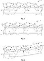
- Fig. 1 shows a cross-sectional view of device 10.
- Device 10 has straight base 12 (of constant thickness T) that is patterned with raised portions 14 on one side. Raised portions 14 form recesses 30 in an area that makes contact to the ground during operation of device 10.
- Each recess 30 is defined by surface 32 of base 12 and wall surfaces 34 extending from base surface 32 in a direction which is perpendicular to direction D of the motion during operation. As shown in Fig. 1 , wall surfaces 34 may be inclined relative to direction D/towards leading section 12a.
- Raised portions 14 have undercut edges 16 and concave parts 18 oriented towards leading section 12a. Raised portions 14 are fin-shaped with convex side 20 oriented towards trailing section 12b. As shown in Fig. 2 , base 12 can be patterned with raised portions 14 and recesses 30 on two sides (or circumferentially).
- Fig. 3 illustrates a modification of device 10 in which base 12 is bent and patterned with raised portions 14 and recesses 30 on the concave side of base 12.
- Fig. 4 illustrates a modification of device 10 in which base 12 is bent and patterned with raised portions 14 and recesses 30 on the convex side of base 12.
- bent base 12 may also be patterned with raised portions 14 and recesses 30 on the concave side and on the convex side (or circumferentially).
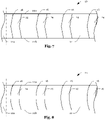
- base 12 may comprise a side confined by edges 22a and 22b extending from leading section 12a to trailing section 12b and undercut edges 16 may extend laterally across the side (from edge 22a to edge 22b).
- Undercut edges 16 extending laterally across the side may be straight, as illustrated in Fig. 6 , but may also be V-shaped, as illustrated in Fig. 7 , or U-shaped, as illustrated in Fig. 8 .
- Fig. 9a and Fig. 9b show a top view and a side view of an exemplary leading section 12a and an exemplary trailing section 12b wherein leading section 12a has leading edge 24a.
- Fig. 10a and Fig. 10b also show a top view and a side view of an exemplary leading section 12a and an exemplary trailing section 12b, wherein leading section 12a has leading edge 24a.
- Fig. 11a and Fig. 11b show a top view and a side view of an exemplary leading section 12a and an exemplary trailing section 12b, wherein leading section 12a has a tip 24b.
- Fig. 10a and Fig. 11a trailing section 12b may have screw holes 26 for attaching device 10 to cultivation/construction equipment (not shown).
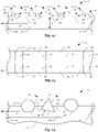
- Fig. 12 illustrates a modification in which raised portions 14 are not (substantially) equidistantly spaced apart.
- Fig. 13 illustrates a modification in which raised portions 14 are equidistantly spaced apart and form a matrix.
- Fig. 14 illustrates a modification in which recesses 30 are formed by particles 36 adhering to layer 38 of base 12.
- Layer 38 may comprise an adhesive and particles 36 may be randomly distributed across layer 38.
- Particles 36 may have different shapes (e.g., with or without edges) and sizes. For example, particles 36 may have a size of more than 0.5 mm.
- Particles 36 may be made of a wear-resistant material such as corundum.
- Fig. 15 shows a flow-chart of a method of working the ground.
- the method comprises step 28 of moving device 10 relative to the ground.
- the pocket formed by concave part 18 is filled with ground material (e.g., soil) which builds-up a protective layer reducing wear and tear regarding base 12.
- ground material e.g., soil
Landscapes
- Life Sciences & Earth Sciences (AREA)
- Engineering & Computer Science (AREA)
- Mechanical Engineering (AREA)
- Soil Sciences (AREA)
- Environmental Sciences (AREA)
- Mining & Mineral Resources (AREA)
- Civil Engineering (AREA)
- General Engineering & Computer Science (AREA)
- Structural Engineering (AREA)
- Soil Working Implements (AREA)
Priority Applications (1)
| Application Number | Priority Date | Filing Date | Title |
|---|---|---|---|
| EP20204225.5A EP3991529A1 (fr) | 2020-10-28 | 2020-10-28 | Dispositif de travail au sol |
Applications Claiming Priority (1)
| Application Number | Priority Date | Filing Date | Title |
|---|---|---|---|
| EP20204225.5A EP3991529A1 (fr) | 2020-10-28 | 2020-10-28 | Dispositif de travail au sol |
Publications (1)
| Publication Number | Publication Date |
|---|---|
| EP3991529A1 true EP3991529A1 (fr) | 2022-05-04 |
Family
ID=73029981
Family Applications (1)
| Application Number | Title | Priority Date | Filing Date |
|---|---|---|---|
| EP20204225.5A Withdrawn EP3991529A1 (fr) | 2020-10-28 | 2020-10-28 | Dispositif de travail au sol |
Country Status (1)
| Country | Link |
|---|---|
| EP (1) | EP3991529A1 (fr) |
Citations (9)
| Publication number | Priority date | Publication date | Assignee | Title |
|---|---|---|---|---|
| US86893A (en) * | 1869-02-09 | Improvement in combined breaker and leveller | ||
| US226531A (en) * | 1880-04-13 | Edwin e | ||
| US1275588A (en) * | 1917-04-24 | 1918-08-13 | Frederick H Myers | Cultivator. |
| US2751736A (en) * | 1953-10-19 | 1956-06-26 | Robert R Hessemer | Drag cutter assembly for clearing land |
| WO2014139733A2 (fr) * | 2013-03-11 | 2014-09-18 | Betek Gmbh & Co. Kg | Pointe de soc ou combinaison d'outil pourvue d'une pointe de soc |
| DE102015122620A1 (de) * | 2014-12-22 | 2016-06-23 | Betek Gmbh & Co. Kg | Werkzeugsystem |
| US20180171587A1 (en) * | 2016-12-15 | 2018-06-21 | Caterpillar Inc. | Serrated Cutting Edge with Ceramic Insert |
| CN108605445A (zh) * | 2016-12-09 | 2018-10-02 | 张伟 | 一种多功能两用耙耱 |
| DE102018108734A1 (de) * | 2018-04-12 | 2019-10-17 | Thomas Jansen | Bodenbearbeitungsvorrichtung |
-
2020
- 2020-10-28 EP EP20204225.5A patent/EP3991529A1/fr not_active Withdrawn
Patent Citations (9)
| Publication number | Priority date | Publication date | Assignee | Title |
|---|---|---|---|---|
| US86893A (en) * | 1869-02-09 | Improvement in combined breaker and leveller | ||
| US226531A (en) * | 1880-04-13 | Edwin e | ||
| US1275588A (en) * | 1917-04-24 | 1918-08-13 | Frederick H Myers | Cultivator. |
| US2751736A (en) * | 1953-10-19 | 1956-06-26 | Robert R Hessemer | Drag cutter assembly for clearing land |
| WO2014139733A2 (fr) * | 2013-03-11 | 2014-09-18 | Betek Gmbh & Co. Kg | Pointe de soc ou combinaison d'outil pourvue d'une pointe de soc |
| DE102015122620A1 (de) * | 2014-12-22 | 2016-06-23 | Betek Gmbh & Co. Kg | Werkzeugsystem |
| CN108605445A (zh) * | 2016-12-09 | 2018-10-02 | 张伟 | 一种多功能两用耙耱 |
| US20180171587A1 (en) * | 2016-12-15 | 2018-06-21 | Caterpillar Inc. | Serrated Cutting Edge with Ceramic Insert |
| DE102018108734A1 (de) * | 2018-04-12 | 2019-10-17 | Thomas Jansen | Bodenbearbeitungsvorrichtung |
Similar Documents
| Publication | Publication Date | Title |
|---|---|---|
| CN108291427B (zh) | 上面具有非平面切削元件的固定切削刀钻头以及其它井下工具 | |
| US7594703B2 (en) | Pick with a reentrant | |
| CN102027171B (zh) | 带垫圈的道路平整截齿 | |
| EP0414751A1 (fr) | Ensemble lame de niveleuse utilisant une plaquette de carbure. | |
| CN110073062A (zh) | 具有带有锥形固位通道的尖端的器具地面接合尖端组件 | |
| CN110073063B (zh) | 具有带有支承肋部的末端的器具末端组件 | |
| RU2680620C1 (ru) | Сменный режущий элемент землеройного орудия | |
| ITTO980801A1 (it) | Elemento tagliente con area di contatto superabrasiva controllata, pun te da perforazione dotate di tale elemento e procedimenti di perfora- | |
| US6446741B1 (en) | Rock drill | |
| CN102535561A (zh) | 多边形硬质合金刀具截齿 | |
| EP3991529A1 (fr) | Dispositif de travail au sol | |
| ES2778653T3 (es) | Elemento de desgaste | |
| JPH05505432A (ja) | 耐磨耗性ストリップ | |
| CN110062832A (zh) | 具有带磨损指示器的尖端的器具尖端组件 | |
| DE112012000963T5 (de) | Einsatz und Abtraganordnung | |
| US20070034288A1 (en) | Stump grinding disk and wear strips therefor | |
| CN215483243U (zh) | 斗齿组件、铲斗及挖掘机 | |
| JP6483737B2 (ja) | ロータリ作業機 | |
| JP2002054390A (ja) | 掘削機用カッタビット | |
| JP7360231B2 (ja) | 切削用チップ及びビット | |
| EP3775409B1 (fr) | Élément d'usure pour un outil de travail | |
| CN104334818B (zh) | 切削元件、切削工具和在钻孔内切削的方法 | |
| JP4502480B2 (ja) | 掘削工具、及び、耐摩耗性部材 | |
| JP6964894B2 (ja) | 畦塗り機 | |
| JP6675529B2 (ja) | タイヤスクレーパ |
Legal Events
| Date | Code | Title | Description |
|---|---|---|---|
| PUAI | Public reference made under article 153(3) epc to a published international application that has entered the european phase |
Free format text: ORIGINAL CODE: 0009012 |
|
| STAA | Information on the status of an ep patent application or granted ep patent |
Free format text: STATUS: THE APPLICATION HAS BEEN PUBLISHED |
|
| AK | Designated contracting states |
Kind code of ref document: A1 Designated state(s): AL AT BE BG CH CY CZ DE DK EE ES FI FR GB GR HR HU IE IS IT LI LT LU LV MC MK MT NL NO PL PT RO RS SE SI SK SM TR |
|
| STAA | Information on the status of an ep patent application or granted ep patent |
Free format text: STATUS: REQUEST FOR EXAMINATION WAS MADE |
|
| 17P | Request for examination filed |
Effective date: 20220711 |
|
| RBV | Designated contracting states (corrected) |
Designated state(s): AL AT BE BG CH CY CZ DE DK EE ES FI FR GB GR HR HU IE IS IT LI LT LU LV MC MK MT NL NO PL PT RO RS SE SI SK SM TR |
|
| GRAP | Despatch of communication of intention to grant a patent |
Free format text: ORIGINAL CODE: EPIDOSNIGR1 |
|
| STAA | Information on the status of an ep patent application or granted ep patent |
Free format text: STATUS: GRANT OF PATENT IS INTENDED |
|
| RIC1 | Information provided on ipc code assigned before grant |
Ipc: E02F 9/28 20060101ALI20240701BHEP Ipc: A01B 35/14 20060101ALI20240701BHEP Ipc: A01B 35/08 20060101ALI20240701BHEP Ipc: A01B 25/00 20060101ALI20240701BHEP Ipc: A01B 23/02 20060101ALI20240701BHEP Ipc: A01B 21/04 20060101ALI20240701BHEP Ipc: A01B 31/00 20060101ALI20240701BHEP Ipc: A01B 35/26 20060101ALI20240701BHEP Ipc: A01B 21/02 20060101AFI20240701BHEP |
|
| INTG | Intention to grant announced |
Effective date: 20240726 |
|
| STAA | Information on the status of an ep patent application or granted ep patent |
Free format text: STATUS: THE APPLICATION IS DEEMED TO BE WITHDRAWN |
|
| 18D | Application deemed to be withdrawn |
Effective date: 20241127 |