EP3991867B1 - Presse plieuse - Google Patents
Presse plieuse Download PDFInfo
- Publication number
- EP3991867B1 EP3991867B1 EP20831598.6A EP20831598A EP3991867B1 EP 3991867 B1 EP3991867 B1 EP 3991867B1 EP 20831598 A EP20831598 A EP 20831598A EP 3991867 B1 EP3991867 B1 EP 3991867B1
- Authority
- EP
- European Patent Office
- Prior art keywords
- bending
- amount
- workpiece
- die
- punch
- Prior art date
- Legal status (The legal status is an assumption and is not a legal conclusion. Google has not performed a legal analysis and makes no representation as to the accuracy of the status listed.)
- Active
Links
Images





Classifications
-
- B—PERFORMING OPERATIONS; TRANSPORTING
- B21—MECHANICAL METAL-WORKING WITHOUT ESSENTIALLY REMOVING MATERIAL; PUNCHING METAL
- B21D—WORKING OR PROCESSING OF SHEET METAL OR METAL TUBES, RODS OR PROFILES WITHOUT ESSENTIALLY REMOVING MATERIAL; PUNCHING METAL
- B21D5/00—Bending sheet metal along straight lines, e.g. to form simple curves
- B21D5/004—Bending sheet metal along straight lines, e.g. to form simple curves with program control
-
- B—PERFORMING OPERATIONS; TRANSPORTING
- B21—MECHANICAL METAL-WORKING WITHOUT ESSENTIALLY REMOVING MATERIAL; PUNCHING METAL
- B21D—WORKING OR PROCESSING OF SHEET METAL OR METAL TUBES, RODS OR PROFILES WITHOUT ESSENTIALLY REMOVING MATERIAL; PUNCHING METAL
- B21D5/00—Bending sheet metal along straight lines, e.g. to form simple curves
- B21D5/006—Bending sheet metal along straight lines, e.g. to form simple curves combined with measuring of bends
-
- B—PERFORMING OPERATIONS; TRANSPORTING
- B21—MECHANICAL METAL-WORKING WITHOUT ESSENTIALLY REMOVING MATERIAL; PUNCHING METAL
- B21D—WORKING OR PROCESSING OF SHEET METAL OR METAL TUBES, RODS OR PROFILES WITHOUT ESSENTIALLY REMOVING MATERIAL; PUNCHING METAL
- B21D5/00—Bending sheet metal along straight lines, e.g. to form simple curves
- B21D5/01—Bending sheet metal along straight lines, e.g. to form simple curves between rams and anvils or abutments
- B21D5/015—Bending sheet metal along straight lines, e.g. to form simple curves between rams and anvils or abutments for making tubes
-
- B—PERFORMING OPERATIONS; TRANSPORTING
- B21—MECHANICAL METAL-WORKING WITHOUT ESSENTIALLY REMOVING MATERIAL; PUNCHING METAL
- B21D—WORKING OR PROCESSING OF SHEET METAL OR METAL TUBES, RODS OR PROFILES WITHOUT ESSENTIALLY REMOVING MATERIAL; PUNCHING METAL
- B21D5/00—Bending sheet metal along straight lines, e.g. to form simple curves
- B21D5/02—Bending sheet metal along straight lines, e.g. to form simple curves on press brakes without making use of clamping means
-
- B—PERFORMING OPERATIONS; TRANSPORTING
- B21—MECHANICAL METAL-WORKING WITHOUT ESSENTIALLY REMOVING MATERIAL; PUNCHING METAL
- B21D—WORKING OR PROCESSING OF SHEET METAL OR METAL TUBES, RODS OR PROFILES WITHOUT ESSENTIALLY REMOVING MATERIAL; PUNCHING METAL
- B21D5/00—Bending sheet metal along straight lines, e.g. to form simple curves
- B21D5/02—Bending sheet metal along straight lines, e.g. to form simple curves on press brakes without making use of clamping means
- B21D5/0272—Deflection compensating means
-
- B—PERFORMING OPERATIONS; TRANSPORTING
- B30—PRESSES
- B30B—PRESSES IN GENERAL
- B30B15/00—Details of, or accessories for, presses; Auxiliary measures in connection with pressing
- B30B15/007—Means for maintaining the press table, the press platen or the press ram against tilting or deflection
-
- B—PERFORMING OPERATIONS; TRANSPORTING
- B30—PRESSES
- B30B—PRESSES IN GENERAL
- B30B15/00—Details of, or accessories for, presses; Auxiliary measures in connection with pressing
- B30B15/02—Dies; Inserts therefor; Mounting thereof; Moulds
-
- B—PERFORMING OPERATIONS; TRANSPORTING
- B30—PRESSES
- B30B—PRESSES IN GENERAL
- B30B15/00—Details of, or accessories for, presses; Auxiliary measures in connection with pressing
- B30B15/14—Control arrangements for mechanically-driven presses
-
- B—PERFORMING OPERATIONS; TRANSPORTING
- B30—PRESSES
- B30B—PRESSES IN GENERAL
- B30B15/00—Details of, or accessories for, presses; Auxiliary measures in connection with pressing
- B30B15/26—Program-control arrangements
-
- G—PHYSICS
- G05—CONTROLLING; REGULATING
- G05B—CONTROL OR REGULATING SYSTEMS IN GENERAL; FUNCTIONAL ELEMENTS OF SUCH SYSTEMS; MONITORING OR TESTING ARRANGEMENTS FOR SUCH SYSTEMS OR ELEMENTS
- G05B19/00—Program-control systems
- G05B19/02—Program-control systems electric
- G05B19/18—Numerical control [NC], i.e. automatically operating machines, in particular machine tools, e.g. in a manufacturing environment, so as to execute positioning, movement or co-ordinated operations by means of program data in numerical form
- G05B19/4097—Numerical control [NC], i.e. automatically operating machines, in particular machine tools, e.g. in a manufacturing environment, so as to execute positioning, movement or co-ordinated operations by means of program data in numerical form characterised by using design data to control NC machines, e.g. CAD/CAM
-
- G—PHYSICS
- G01—MEASURING; TESTING
- G01B—MEASURING LENGTH, THICKNESS OR SIMILAR LINEAR DIMENSIONS; MEASURING ANGLES; MEASURING AREAS; MEASURING IRREGULARITIES OF SURFACES OR CONTOURS
- G01B11/00—Measuring arrangements characterised by the use of optical techniques
- G01B11/26—Measuring arrangements characterised by the use of optical techniques for measuring angles or tapers; for testing the alignment of axes
-
- G—PHYSICS
- G05—CONTROLLING; REGULATING
- G05B—CONTROL OR REGULATING SYSTEMS IN GENERAL; FUNCTIONAL ELEMENTS OF SUCH SYSTEMS; MONITORING OR TESTING ARRANGEMENTS FOR SUCH SYSTEMS OR ELEMENTS
- G05B2219/00—Program-control systems
- G05B2219/30—Nc systems
- G05B2219/36—Nc in input of data, input key till input tape
- G05B2219/36203—Bending of workpiece, also for long slender workpiece
-
- G—PHYSICS
- G05—CONTROLLING; REGULATING
- G05B—CONTROL OR REGULATING SYSTEMS IN GENERAL; FUNCTIONAL ELEMENTS OF SUCH SYSTEMS; MONITORING OR TESTING ARRANGEMENTS FOR SUCH SYSTEMS OR ELEMENTS
- G05B2219/00—Program-control systems
- G05B2219/30—Nc systems
- G05B2219/45—Nc applications
- G05B2219/45143—Press-brake, bending machine
Definitions
- the present invention relates to a press brake according to the features of the preamble of claim 1 and to a method of controlling a press brake according to the features of the preamble of claim 6.
- Such a press brake and such a method are for example disclosed in document JP-A-2012 206136 .
- a so-called partial bending method (typical air bending method) is used when subjecting a workpiece to multistage bending with a press brake.
- the partial bending method is a method in which when pressing the workpiece with a punch, the workpiece is bent in a state where the workpiece is not brought into contact with the bottom of a groove of a die, and a rear surface of the workpiece floats in the groove. Therefore, any curvature can be given to the workpiece by adjusting a pressing amount of the punch.
- there are a bottoming method and a coining method According to these methods, the workpiece is brought into contact with the bottom of the groove of the die by the pressing of the punch.
- a stroke value of a punch is determined in advance, and forming is performed based on the stroke value.
- a relation between the stroke value and a realized angle depends on Young's modulus of the material of a workpiece and the thickness of the workpiece.
- Young's modulus is determined in advance, and the thickness of the workpiece.
- An object of the present invention is to improve bending accuracy of multistage bending.
- a press brake is a press brake that performs bending with respect to a workpiece by a die and a punch.
- the press brake includes: a die that supports a rear surface of the workpiece; a punch that is arranged so as to be opposed to the die and moves in an upper-lower direction relative to the die to press a front surface of the workpiece; a crowning mechanism that changes a crowning amount that is an amount of upward projection of a middle portion of the die relative to both end portions of the die in a die longitudinal direction; a bending amount measuring device that measures a middle bending amount and end bending amounts, the middle bending amount being a bending amount of a width direction middle portion of the workpiece, the end bending amounts being bending amounts of width direction end portions of the workpiece; and a control device.
- the control device acquires from the bending amount measuring device the middle bending amount and the end bending amounts of the workpiece that has been subjected to the bending by the die and the punch.
- the control device corrects the crowning amount in accordance with a difference between a shortage of the middle bending amount from a target bending amount and a shortage of each end bending amount from the target bending amount and drives the crowning mechanism.
- the distortion of the die is corrected, and in addition, the crowning amount (and the tilt amount, if necessary) is also corrected in accordance with the bending amount of an end portion of the workpiece in consideration of a change in a springback amount that changes due to the variations of Young's modulus from the nominal value of the material and the error of the thickness from the nominal value. Therefore, in the entire forming after the forming of the edge portion, the forming accuracy improves regardless of the above error, and therefore, the dimensional accuracy of the entire product improves.
- bending accuracy of multistage bending can be improved.
- FIG. 1A is a front view of a press brake 1 according to the embodiment.
- FIG. 1B is a sectional view of the press brake 1 taken along line IB-IB of FIG. 1A .
- FIG. 2 is a block diagram showing a functional configuration of the press brake 1 according to the embodiment.
- the press brake 1 shown in FIGS. 1 and 2 can perform multistage bending with respect to a plate-shaped workpiece 90 that is long and wide.
- a circular tube body having a relatively large diameter can be formed.
- One example of such circular tube body is a skin of an aircraft body portion.
- the press brake 1 includes a conveying mechanism (conveying device) 2, a die 3, a punch 4, a crowning mechanism (crowning device) 5, a punch supporting portion 6, a punch driving mechanism (punch driving device) 7, a bending amount measuring device 8, and a control device 9.
- the conveying mechanism 2 intermittently conveys the workpiece 90 in a conveying direction (work longitudinal direction).
- a specific configuration of the conveying mechanism 2 is not especially limited.
- the conveying mechanism 2 may be comprised by a conveyor, a robot including a hand at a tip of a robot arm, or the like.
- the die 3 includes a groove portion 13 having a U-shaped section, a V-shaped section, or the like in a short-length direction. According to need, urethane or the like may be disposed between the die 3 and the workpiece 90, or a plate with which the workpiece 90 is brought into contact may be disposed.
- the "conveying direction" of the workpiece 90 and a "die longitudinal direction” are within a horizontal plane and are orthogonal to each other.
- the workpiece 90 is placed on the press brake 1 such that at least in the vicinity of a portion supported by the die 3, a longitudinal direction of the workpiece 90 coincides with the conveying direction (see FIG. 1B ), and a width direction of the workpiece 90 coincides with the die longitudinal direction (see FIG. 1A ).
- the punch 4 is located so as to be opposed to the die 3 in a direction orthogonal to both the conveying direction and the die longitudinal direction. In the present embodiment, this opposing direction is an "upper-lower direction," and the punch 4 is arranged above the die 3.
- the groove portion 13 of the die 3 has a groove shape that is open upward as shown in FIG. 1B , and extends in the die longitudinal direction at an upper portion of the die 3.
- the sectional shape of the groove portion 13, the dimension of the opening portion in the conveying direction, the depth of the opening portion, and the like are suitably selected.
- the punch 4 is supported by a lower portion of the punch supporting portion 6 arranged above the die 3 and is opposed to the die 3 in the upper-lower direction.
- the punch driving mechanism 7 moves the punch supporting portion 6 and the punch 4, supported by the punch supporting portion 6, relative to the die 3 in the upper-lower direction.
- the punch driving mechanism 7 includes a first driving mechanism (first driving device) 7a and a second driving mechanism (second driving device) 7b which are separated from each other in the die longitudinal direction.
- each of the first driving mechanism 7a and the second driving mechanism 7b may be comprised by a hydraulic cylinder arranged such that a rod thereof is directed in the upper-lower direction.
- the first driving mechanism 7a and the second driving mechanism 7b are comprised by separate hydraulic cylinders and can independently adjust stroke amounts (rod extension amounts).
- the punch supporting portion 6 and the punch 4 can be moved in parallel in the upper-lower direction while maintaining the postures of the punch supporting portion 6 and the punch 4.
- the postures (tilt amounts, tilt angles) of the punch supporting portion 6 and the punch 4 can be changed arbitrarily.
- the punch can stroke while being maintained in a horizontal state, and in addition, can incline (tilt) at an arbitrary angle. Therefore, the first driving mechanism 7a and the second driving mechanism 7b serve as not only punch driving mechanisms but also tilt mechanisms.
- the die 3 is supported by the crowning mechanism 5.
- the amount (hereinafter “crowning amount CR") of upward projection of a middle portion of the die 3 in the die longitudinal direction relative to both end portions of the die 3 in the die longitudinal direction is changeable by the driving the crowning mechanism 5.
- the crowning mechanism 5 is a mechanism that changes the crowning amount CR.
- the configuration of the crowning mechanism 5 is not especially limited.
- a known crowning mechanism using a wedge is adopted (see FIG. 1A ).
- the crowning mechanism 5 includes a lower element 5A and an upper element 5B that are separated in the upper-lower direction.
- saw teeth-shaped engaging portions 14a including sliding surfaces are formed on an upper surface of the lower element 5A
- saw teeth-shaped engaging portions 14b including sliding surfaces are formed on a lower surface of the upper element 5B.
- the sliding surfaces of the engaging portions 14a and the sliding surfaces of the engaging portions 14b are in contact with each other.
- the tilt angles of the sliding surfaces of the engaging portions 14a are different from each other, and the tilt angles of the sliding surfaces of the engaging portions 14b are different from each other.
- the crowning mechanism 5 further includes a crowning driving portion 15 that moves the lower element 5A or the upper element 5B in the die longitudinal direction.
- the crowning driving portion 15 is constituted by: a servomotor and a screw mechanism; or a hydraulic cylinder.
- the crowning driving portion 15 shown in FIG. 1 is one example.
- Another example may be such that: hydraulic cylinders supporting the die 3 from below are arranged in the longitudinal direction of the die 3; and the crowning amount CR is changed by adjusting expansion lengths of the hydraulic cylinders.
- the bending amount measuring device 8 includes a sensor that measures the bending amount of the workpiece 90. As the bending amount of the workpiece 90, the bending amount measuring device 8 measures a middle bending amount and end bending amounts. The middle bending amount is a bending amount of a width direction middle portion of the workpiece 90, and the end bending amounts are bending amounts of width direction end portions of the workpiece 90. As the end bending amounts, the bending amount measuring device 8 measures a first end bending amount and a second end bending amount. The first end bending amount is a bending amount of a width direction first end portion of the workpiece 90, and the second end bending amount is a bending amount of a width direction second end portion of the workpiece 90.
- the bending amount measuring device 8 may measure the bending amount of only one portion of the width direction middle portion of the workpiece 90 or may measure the bending amounts of plural portions of the width direction middle portion of the workpiece 90. In the present embodiment, as an example of the latter case, the bending amount measuring device 8 measures a first middle bending amount and a second middle bending amount.
- the first middle bending amount is a bending amount of a portion closer to a width direction first end than a width direction middle of the workpiece 90
- the second middle bending amount is a bending amount of a portion closer to a width direction second end than the width direction middle of the workpiece 90.
- the bending amount measuring device 8 measures the bending amounts of the workpiece 90 at the width direction portions of the workpiece 90.
- the bending amount measuring device 8 includes a single sensor and a scanning mechanism (scanning device) that moves the sensor in the die longitudinal direction.
- the single sensor scans the workpiece 90 to suitably measure the bending amounts of the portions of the workpieces 90.
- the bending amount measuring device may measure the bending amounts of the portions of the workpiece 90 by using plural sensors.
- the "bending amount” measured by the bending amount measuring device 8 may be any value and is not especially limited as long as the bending amount is a measured value regarding a contour in the longitudinal direction of the workpiece and is an index by which the degree of the bending given to the workpiece 90 can be quantitatively evaluated.
- index include: a curvature radius of the workpiece 90; a chord length between two points away from each other in the longitudinal direction (circumferential direction) of the workpiece 90; an arc height corresponding to a circular arc between the two points; and a bending angle of the workpiece 90.
- the sensor constituting the bending amount measuring device 8 is arranged downstream of the die 3 in the conveying direction.
- another sensor may be arranged upstream of the die 3 in the conveying direction.
- the sensors are arranged downstream and upstream of the die 3 in the conveying direction (see FIG. 1B ).
- the sensor at the upstream side is suitably used, for example, when considering the posture of the workpiece 90 for the correction of a detection value of the sensor at the downstream side, when measuring an initial bending amount of the workpiece 90, or when conveying the workpiece 90 in an opposite direction from the downstream side to the upstream side.
- the control device 9 controls the conveying mechanism 2, the punch driving mechanism 7, and the crowning mechanism 5.
- the control device 9 corrects the stroke amount of the punch driving mechanism 7, i.e., a pressing amount and tilt amount of the punch 4 with respect to the die 3 or the workpiece 90.
- the control device 9 corrects a movement amount of the crowning driving portion 15 of the crowning mechanism 5, i.e., the crowning amount CR.
- the stroke amount and tilt amount of the punch driving mechanism 7 are corrected in accordance with the above bending amounts, i.e., the pressing amount of the punch 3 is corrected in accordance with the above bending amounts.
- the stroke amount and tilt amount of the punch driving mechanism 7, i.e., the pressing amount of the punch 3 can be corrected especially in accordance the end bending amount (the bending amount of the width direction end portion of the workpiece 90).
- Positions at which the bending amounts to be referred at the time of the correction are measured may be any positions on the workpiece 90 and are, for example, positions at an end portion (especially a downstream end portion) of the workpiece 90 in the conveying direction.
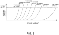
- a relation between the pressing amount and the bending amount differs depending on the thickness of the workpiece 90. Therefore, a storage portion 9a stores a database that defines a correspondence relation of the bending amounts with respect to the pressing amounts for each thickness.
- FIG. 3 is a graph for explaining contents of the database.
- the bending amount increases as the pressing amount increases.
- the larger pressing amount is required for the workpiece having thinner thickness. This is because springback characteristics of these workpieces differ due to the thickness difference.
- the above tendency needs to be considered.
- portions having respective thicknesses different from each other are adjacent to each other, rigidities of the portions influence each other.
- the database of the relations between the bending amounts (bending angles) and the pressing amounts (stroke amounts) for various thicknesses is made, the relations having such tendency.
- the database is stored in the storage portion 9a. More specifically, a formula or a table by which the bending amount is acquired from the pressing amount is prepared in advance for each of Young's modulus, thickness, and situations, such as surrounding environment at the time of forming and a condition of the workpiece. These may be prepared by experiments or simulation.
- the crowning amount CR is determined in accordance with a pressing load applied to the workpiece 90 and is corrected in accordance with a difference between the middle bending amount and an average value of the end bending amounts.
- a relation between the crowning amount and the bending amount changes in accordance with the thickness.
- the storage portion 9a stores a database that defines a correspondence relation of the bending amount with respect to the crowning amount for each thickness.
- FIG. 4 is a flow chart of the multistage bending performed by the press brake 1 with respect to the workpiece 90, the multistage bending including the operation of correcting the stroke amount, the crowning amount, and the tilt amount by the control device 9.
- This operation includes a bending step (S100), a determining step (S200), a correcting step (S300), and a multistage bending step (S400) which are performed after the workpiece 90 is conveyed to an appropriate position.
- S100 a bending step
- S200 determining step
- S300 correcting step
- S400 multistage bending step
- each of the stroke amount and tilt amount of the punch 4 and the crowning amount of the die 3 is set to a predetermined initial value (S2).
- S2 used as an example (first initial value example) of the initial value of the stroke amount may be such a value that it is expected from a sectional dimension of the pressed portion of the workpiece 90 that a target bending amount can be realized.
- the stroke amount is set as the pressing amount by which the rear surface of the workpiece 90 is not brought into contact with the bottom of the groove portion 13 of the die 3.
- the above case where the rear surface of the workpiece 90 is not brought into contact with the bottom of the groove portion 13 of the die 3 denotes a case where the rear surface of the workpiece 90 is not directly brought into contact with the bottom of the groove portion 13, and examples of such case include: a case where urethane or the like is embedded in at least a part of the groove portion 13, and the rear surface of the workpiece 90 is brought into contact with this embedded portion; and a case where a bottom-contact die deforms mechanically or elastically.
- an example (second initial value example) of the initial value of the stroke amount may be set to a value slightly smaller than such a value that it is expected that the target bending amount can be realized.
- the initial value may be set to such a stroke amount that it is expected that the bending amount becomes around 90% (85% or more and 95% or less, for example) of the target bending amount.
- the bending step (S100) is executed.
- the pressing of the workpiece 90 and the conveyance (S3) of the workpiece 90 are alternately and repeatedly performed until the pressed portion reaches a measurement range of the bending amount measuring device 8 (S4).
- the pressing and the conveyance are repeated in order of the pressing of the punch 4, the conveyance of the workpiece 90, the stop of the conveyance, and the pressing of the punch 4.
- the initial value of the stroke amount is set such that the bending amount given to the workpiece 90 in the first bending step (S100) becomes slightly smaller than the target bending amount required for the final product. With this, excessive bending can be prevented.
- the workpiece 90 is bent insufficiently as compared to a target value.
- the first bending step (S100) it is not essential to repeatedly perform the pressing and the conveyance (S3) until the pressed portion of the workpiece 90 reaches the measurement range. For example, after the pressing and the conveyance of the workpiece 90 (S3) are repeated a predetermined number of times, only the conveyance may be performed without performing the pressing such that the pressed portion of the workpiece 90 reaches the measurement range.
- the determining step (S200) is executed.
- the bending amounts given to the workpiece 90 in the above bending step (S100) are measured (S5), and then, whether or not each of the measured bending amounts coincides with the target value (whether or not each of the measured bending amounts falls within a predetermined allowable range set based on the target value) is determined, i.e., whether each of the measured bending amounts is successful or unsuccessful is determined (S6).
- the bending amounts of four portions of the workpiece 90 are measured.
- the bending amounts of four portions of the workpiece 90 are: the first end bending amount that is the bending amount of the first end portion in the die longitudinal direction; the second end bending amount that is the bending amount of the second end portion in the die longitudinal direction; the first middle bending amount that is the bending amount of the portion closer to the first end with respect to the middle portion in the die longitudinal direction; and the second middle bending amount that is the bending amount of the portion closer to the second end with respect to the middle portion in the die longitudinal direction.
- a shortage (differential value) of each measured bending amount from the target bending amount is also calculated.
- at least a part of the circular tube body is assumed to be formed from the workpiece 90.
- the target bending amount is a single value.
- a shortage (first end shortage) of the first end bending amount from the target bending amount, a shortage (second end shortage) of the second end bending amount from the target bending amount, a shortage (first middle shortage) of the first middle bending amount from the target bending amount, and a shortage (second middle shortage) of the second middle bending amount from the target bending amount are calculated.
- the workpiece 90 is pressed by the stroke amount that is smaller than such a stroke amount that it is expected that the target bending amount can be realized. Therefore, in this case, the measurement value of the bending amount does not fall within the allowable range in the determining step (S200), and it is determined that the measurement value of the bending amount is unsuccessful (No in S6).
- the correcting step (S300) is executed.
- the correcting step (S300) one of two types of operations is selected and executed in accordance with the degree of the unsuccessful value. Specifically, when the degree of the unsuccessful value is relatively low, i.e., when the measured bending amount of the pressed portion is such a bending amount that it is unnecessary to bend the pressed portion again, a first option is executed, i.e., the correction value for one side bending is acquired to perform the forming of a subsequent portion of the workpiece 90 without performing two times bending (S8).
- Step S6 when the degree of the unsuccessful value is relatively high, i.e., when the measured bending amount of the pressed portion is such a bending amount that it is necessary to perform the bending again (two times bending), a second option is executed, i.e., the correction value for both side bending is acquired (S9), the conveyance of the workpiece 90 to the initial position for the two times bending is performed (S10) to perform the two times bending. Then, the above operations are performed again from Step S3 described above. A case where it is determined in Step S6 that the bending amount is successful will be described later.
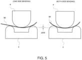
- Step S6 of the determining step (S200) when it is determined in Step S6 of the determining step (S200) that the bending amount is insufficient (unsuccessful), the correction value for the one side bending (S8) or the correction value for the both side bending (S9) is acquired in the correcting step (S300) based on the shortage of the bending amount. Differences between the correction value for the one side bending and the correction value for the both side bending will be described with reference to FIG. 5 .
- a left diagram in FIG. 5 shows that only a portion of the workpiece 90 which portion is located downstream of the pressed portion, pressed by the punch 4, in the conveying direction has already been subjected to the forming.
- the bending in this state is called “one side bending" for convenience sake.
- a right diagram in FIG. 5 shows that both portions of the workpiece 90 which portions are respectively located downstream and upstream of the pressed portion, pressed by the punch 4, in the conveying direction have already been subjected to the forming.
- the bending in this state is called “both side bending” for convenience sake.
- the correction value is acquired by referring to a database corresponding to the one side bending or a database corresponding to the both side bending or referring to the same database in an offset manner in accordance with whether the next forming is the one side bending or the both side bending (S8, S9).
- control device 9 refers to the database of the storage portion 9a to acquire correction amounts of the stroke amount, the crowning amount, and the tilt amount in accordance with the shortage of the measured bending amount, i.e., a differential correction amount of the measured value of the first driving mechanism 7a from the target value and a differential correction amount of the measured value of the second driving mechanism 7b from the target value, and based on these, the control device 9 corrects the stroke amount, the crowning amount, and the tilt amount.
- the initial value of the first driving mechanism 7a is corrected in accordance with the first end shortage
- the initial value of the second driving mechanism 7b is corrected in accordance with the second end shortage
- the initial value of the crowning amount is corrected in accordance with a difference between the end shortage and the middle shortage.
- the middle shortage is larger than the end shortage
- the initial value of the crowning amount is corrected so as to be increased.
- the middle shortage is smaller than the end shortage
- the initial value of the crowning amount is corrected so as to be reduced.
- the correction amount to the initial value of the crowning amount increases.
- the bending amounts are measured at two middle positions and two end positions.
- a method of deriving the middle shortage (or a representative value of the middle shortage) and the end shortage (or a representative value of the end shortage) is not especially limited.
- the control device 9 derives an average value, a maximum value, or a minimum value from the first middle shortage and the second middle shortage.
- the control device 9 derives an average value, a maximum value, or a minimum value from the first end shortage and the second end shortage.
- Step S7 when it is determined in Step S7 that the two times bending is necessary (No in S7), the correction value for the both side bending is acquired (S9), and the workpiece 90 is conveyed to the initial position for the two times bending (S10).
- the workpiece 90 is conveyed such that a first forming target portion (first row) in the portion to be subjected to the two times bending is located right under the punch 4.
- the two times bending is executed by performing Step S3 and the subsequent steps again.
- the target bending amount can be surely given to the workpiece 90.
- high forming accuracy can be realized in partial bending.
- Step 9 the subsequent steps may be performed again according to need, and the bending (S100) may be executed.
- the determining step (S200) after the second bending (S100) may be omitted, and the next step may be performed.
- Step S6 of the determining step (S200) when it is determined in Step S6 of the determining step (S200) that the measured bending amount coincides with the target value (i.e., the measured bending amount is successful) (Yes in S6), the multistage bending step (S400) is executed. To be specific, it is determined whether or not the formed range of the workpiece 90 has been subjected to the forming to the last, i.e., to the final row (No in S11; S13).
- Step S13 and the subsequent steps are executed as the multistage bending step (S400).
- the multistage bending is terminated.
- Step S6 When it is determined that the bending amount measured in Step S6 does not coincide with the target value (i.e., the bending amount measured in Step S6 is unsuccessful) (No in S6), and it is also determined that the two times bending is unnecessary since the degree of the unsuccessful value is low (Yes in S7), the correction value for the one side bending is acquired based on the database (S8). After that, as with the above, Step S13 and the subsequent steps are executed as the multistage bending step (S400). When the workpiece 90 has been subjected to the forming to the final row, the multistage bending is terminated.
- the operations shown in FIG. 4 are operations in which: the bending amounts of all the formed portions of the workpiece 90 are basically measured after the forming; the successful-unsuccessful determinations regarding whether or not the bending amounts coincide with the target value are performed; and the two times bending is performed based on the results of the determinations according to need.
- the successful-unsuccessful determination may be performed with respect to the measured bending amount of only a portion of the workpiece 90 (typically, the downstream end portion of the workpiece 90 in the conveying direction) after the forming, and the remaining bending may be performed based on the correction value obtained from the result of the determination.
- Step S13 when it is determined in Step S13 that the workpiece 90 has not yet been subjected to the forming to the final row (No in S13), the conveyance (S14) and forming (S15) of the workpiece 90 may be repeatedly performed until the forming of the final row is finished.
- the portion subjected to the successful-unsuccessful determination is not limited to one portion on the workpiece 90.
- the successful-unsuccessful determination may be performed for plural portions, and the correction value may be acquired each time the successful-unsuccessful determination is performed, and then, the stroke amount and the like may be corrected.
- the correction based on the result of the successful-unsuccessful determination may be performed with respect to the vicinity of this changing portion in addition to the downstream end portion of the workpiece 90 in the conveying direction.
- the successful-unsuccessful determination based on the changed target bending amount may be additionally performed.
- the two times bending may be then performed with respect to necessary portions of the workpiece 90.
- the determining step (S200) may be performed for respective portions of the workpiece 90, and the correction values of the portions subjected to the determination may be acquired in accordance with the results of the determination and stored in the storage portion 9a.
- FIGS. 7A to 7C are graphs in which a horizontal axis indicates the position in the width direction of the workpiece 90, and a vertical axis indicates the bending amount (contour, bending angle) at the time of the measurement (S5).
- a horizontal axis indicates the position in the width direction of the workpiece 90
- a vertical axis indicates the bending amount (contour, bending angle) at the time of the measurement (S5).
- the bending amounts of three positions that are the width direction first end portion, the width direction middle portion, and the width direction second end portion in the workpiece 90 are shown.
- FIGS. 8A and 8B are graphs for explaining a method of acquiring the correction value of the stroke amount and the correction value of the crowning amount with respect to the shortage of the bending amount.
- the shortage of the bending amount uniformly increases in order of the second end portion, the middle portion, and the first end portion.
- the measured bending amount coincides with the target bending amount.
- the entire posture of the punch supporting portion 6 is inclined (tilted) such that one end portion thereof approaches the die 3.
- the stroke amount of the first driving mechanism 7a located at one end portion of the punch driving mechanism 7 is corrected so as to be increased, and the crowning amount does not have to be corrected.
- a graph G1 shown in FIG. 8A indicates a relation between the stroke amount and the bending amount regarding a predetermined thickness and can be selected from the graphs of the respective thicknesses shown in FIG. 3 .
- a graph of the thickness in which the bending amount reaches a target bending amount R1 by a stroke amount St1 adopted at the time of the execution of the previous bending (S100) can be selected.
- FIG. 8A shows that: the first driving mechanism 7a is driven by the stroke amount St1; and as a result, a bending amount R2 that is smaller than the target bending amount R1 is achieved at the first end portion of the workpiece 90.
- the graph G1 is substantially parallelly moved in a positive direction of the stroke amount until the graph G1 coincides with the stroke amount St1 and the bending amount R2.
- a graph G2 is prepared.
- a differential value ⁇ St between the stroke amount St2 corresponding to the target bending amount R1 on the graph G2 and the stroke amount St1 is acquired.
- the differential value ⁇ St obtained as above can be used as the correction value of the stroke amount of the first driving mechanism 7a.
- the measured bending amount coincides with the target bending amount at each of the first end portion and the second end portion, but the measured bending amount is smaller than the target bending amount at the middle portion.
- the crowning amount of the middle portion of the die 3 is increased by the amount corresponding to ⁇ St shown in FIG. 8B .
- the crowning amount of the crowning mechanism 5 (crowning driving portion 15) is corrected so as to be increased, and the stroke amount of the punch driving mechanism 7 does not have to be corrected.
- a method of acquiring the correction value of the crowning amount a method similar to the above method explained with reference to FIGS. 8A and 8B may be adopted.
- the corrected bending amount is smaller than the target bending amount at each of the first end portion, the middle portion, and the second end portion.
- the shortage of the bending amount of the second end portion is larger than the shortage of the bending amount of the first end portion, and unlike FIG. 7A , the shortage of the bending amount does not change uniformly.
- the stroke amount is insufficient entirely in the width direction, and both the tilt amount and the crowning amount need to be corrected.
- the stroke amounts (and the tilt amounts) of the first driving mechanism 7a and the second driving mechanism 7b and the crowning amount of the die 3 which correspond to the portions where the stroke amount is insufficient may be corrected.
- the correction value of the stroke amount and the correction value of the crowning amount may be acquired based on the respective shortages by a method similar to the method explained with reference to FIGS. 8A and 8B .
- the bending amount measuring device 8 is arranged downstream of the die 3 in the conveying direction.
- the bending amount measuring device 8 may be arranged inside the die, i.e., right under a place where the pressing is performed.
- the pressing and the conveyance of the workpiece are performed in the first bending step S100 in the flow chart of FIG. 4 (S3), the bending amount can be measured during the pressing by arranging the bending amount measuring device 8 inside the die. Therefore, the conveyance of the workpiece for the measurement is unnecessary.
- circuitry or processing circuitry which includes general purpose processors, special purpose processors, integrated circuits, ASICs ("Application Specific Integrated Circuits"), conventional circuitry and/or combinations thereof which are configured or programmed to perform the disclosed functionality.
- Processors are considered processing circuitry or circuitry as they include transistors and other circuitry therein.
- the processor may be a programmed processor which executes a program stored in a memory.
- the circuitry, units, or means are hardware that carry out or are programmed to perform the recited functionality.
- the hardware may be any hardware disclosed herein or otherwise known which is programmed or configured to carry out the recited functionality.
- the hardware is a processor which may be considered a type of circuitry
- the circuitry, means, or units are a combination of hardware and software, the software being used to configure the hardware and/or processor.
- the present invention is applicable to a press brake that subjects a workpiece to bending.
Landscapes
- Engineering & Computer Science (AREA)
- Mechanical Engineering (AREA)
- Human Computer Interaction (AREA)
- Manufacturing & Machinery (AREA)
- Physics & Mathematics (AREA)
- General Physics & Mathematics (AREA)
- Automation & Control Theory (AREA)
- Bending Of Plates, Rods, And Pipes (AREA)
Claims (9)
- Presse-plieuse qui effectue un pliage relativement à une pièce à usiner (90) au moyen d'une matrice et d'un poinçon, la presse-plieuse comprenant :une matrice (3) pouvant supporter une surface arrière de la pièce à usiner,un poinçon (4) agencé de manière à faire face à la matrice et pouvant se déplacer dans une direction haut-bas par rapport à la matrice pour presser une surface avant de la pièce à usiner,un mécanisme de bombage (5) pouvant modifier une quantité de bombage, consistant en une quantité de bombement vers le haut, d'une partie dite médiane de la matrice par rapport aux deux parties terminales de la matrice, vu dans une direction longitudinale de la matrice,un dispositif de mesure de quantité de pliage (8) qui mesure une quantité de pliage médian et des quantités de pliage terminal, la quantité de pliage médian étant la quantité de pliage d'une partie médiane, vu dans le sens de la largeur, de la pièce à usiner, les quantités de pliage terminal étant des quantités de pliage de parties terminales, vu dans le sens de la largeur, de la pièce à usiner ; ladite direction de la largeur de la pièce à usiner coïncidant avec la direction longitudinale de la matrice, etun dispositif de commande (9) ;ledit dispositif de commande acquérant, en provenance du dispositif de mesure de quantité de pliage, la quantité de pliage médian et les quantités de pliage terminal concernant la pièce qui a été soumise au pliage par la matrice et le poinçon ;caractérisée en ce quele dispositif de commande (9) corrige la quantité de bombage en fonction d'une différence entre une insuffisance concernant la quantité de pliage médian par rapport à une quantité de pliage cible et une insuffisance concernant chaque quantité de pliage terminal par rapport à la quantité de pliage cible et actionnant le mécanisme de bombage (5).
- Presse-plieuse selon la revendication 1, comprenant en outre un mécanisme d'inclinaison qui modifie une quantité d'inclinaison liée à un angle d'inclinaison de la matrice (3) entière ou à un angle d'inclinaison du poinçon (4) entier, et dans laquelle :le dispositif de commande (9) acquiert, en provenance du dispositif de mesure de quantité de pliage (8) les quantités de pliage terminal des deux parties terminales de la pièce qui a été soumise au pliage par la matrice et le poinçon, etle dispositif de commande corrige la quantité d'inclinaison en fonction d'une différence entre les insuffisances de quantités de pliage terminal par rapport aux quantités de pliage cibles et actionne le mécanisme d'inclinaison.
- Presse-plieuse selon la revendication 1 ou 2, dans laquelle :le dispositif de commande (9) acquiert, en provenance du dispositif de mesure de quantité de pliage (8), les quantités de pliage terminal de la pièce (90) qui a été soumise au pliage par la matrice (3) et le poinçon (4), etle dispositif de commande corrige une quantité de pression exercée par le poinçon sur la pièce à usiner en fonction des insuffisances de quantités de pliage terminal par rapport aux quantités de pliage cibles et actionne le poinçon.
- Presse-plieuse selon l'une quelconque des revendications 1 à 3, comprenant en outre un mécanisme d'actionnement de poinçon (7) comprenant un premier mécanisme d'actionnement (7a) qui actionne le poinçon (4) dans la direction haut-bas au niveau d'une partie terminale, vu dans la direction longitudinale de la matrice, et un deuxième mécanisme d'actionnement (7b) qui actionne le poinçon dans la direction haut-bas au niveau de l'autre partie terminale, vu dans la direction longitudinale de la matrice ;ledit dispositif de commande (9) acquérant une première quantité de pliage terminal et une deuxième quantité de pliage terminal en provenance du dispositif de mesure de quantité de pliage (8), ladite première quantité de pliage terminal étant une quantité de pliage d'une première partie terminale, vu dans le sens de la largeur de la pièce (90), qui a été soumise au pliage par la matrice (3) et le poinçon, ladite deuxième quantité de pliage terminal étant une quantité de pliage d'une deuxième partie terminale, vu dans le sens de la largeur de la pièce, qui a été soumise au pliage par la matrice et le poinçon ;ledit dispositif de commande déterminant une quantité d'exploitation du premier mécanisme d'actionnement en fonction d'une insuffisance entre la première quantité de pliage terminal et la quantité de pliage cible, etledit dispositif de commande déterminant une quantité d'exploitation du deuxième mécanisme d'actionnement en fonction d'une insuffisance entre la deuxième quantité de pliage terminal et la quantité de pliage cible.
- Presse-plieuse selon l'une quelconque des revendications 1 à 4, dans laquelle lorsque l'insuffisance de la partie médiane est supérieure à l'insuffisance des parties terminales, la valeur initiale de la quantité de bombage est corrigée à la baisse, et lorsque l'insuffisance de la partie médiane est inférieure à l'insuffisance des parties terminales, la valeur initiale de la quantité du bombage est corrigée à la hausse.
- Procédé de commande d'une presse-plieuse, la presse-plieuse comprenant :une matrice (3),un poinçon (4) agencé de manière à faire face à la matrice et se déplaçant dans une direction haut-bas par rapport à la matrice pour presser une surface avant de la pièce à usiner (90), etun mécanisme de bombage (5) modifiant une quantité de bombage, consistant en une quantité de bombement vers le haut, d'une partie dite médiane de la matrice par rapport aux deux parties terminales de la matrice, vu dans une direction longitudinale de la matrice ;le procédé comprenant les étapes consistant à :presser la pièce avec le poinçon pour effectuer un pliage,transporter la pièce pressée, etacquérir une quantité de pliage médian et des quantités de pliage terminal, la quantité de pliage médian étant la quantité de pliage d'une partie médiane, vu dans le sens de la largeur, de la pièce à usiner pressée par le poinçon, les quantités de pliage terminal étant des quantités de pliage de parties terminales, vu dans le sens de la largeur, de la pièce à usiner pressée par le poinçon ;caractérisé par les étapes suivantes consistant à :corriger la quantité de bombage en fonction d'une différence entre une insuffisance concernant la quantité de pliage médian par rapport à une quantité de pliage cible et une insuffisance concernant chaque quantité de pliage terminal par rapport à la quantité de pliage cible, ettransporter à nouveau la pièce (90) vers une position de pliage, actionner le mécanisme de bombage (5) compte tenu de la quantité de bombage corrigée, et presser la pièce à l'aide du poinçon (4) pour effectuer à nouveau le pliage.
- Procédé selon la revendication 7, dans lequel :la presse-plieuse comprend en outre un mécanisme d'inclinaison qui modifie une quantité d'inclinaison liée à un angle d'inclinaison de la matrice (3) entière ou une quantité d'inclinaison du poinçon (4) entier ;le procédé comprenant en outre la correction de la quantité d'inclinaison en fonction des insuffisances concernant les quantités de pliage terminal des deux parties terminales de la pièce (90) par rapport aux quantités de pliage cibles, etl'étape consistant à effectuer à nouveau le pliage comprenant en outre l'actionnement du mécanisme d'inclinaison compte tenu de la quantité d'inclinaison corrigée, et le pressage de la pièce par le poinçon en fonction des insuffisances concernant les quantités de pliage terminal des deux parties terminales de la pièce par rapport aux quantités de pliage cibles pour effectuer à nouveau le pliage.
- Procédé selon la revendication 6, dans lequel l'étape consistant à effectuer à nouveau le pliage comprend en outre la correction d'une quantité de pression du poinçon (4) par rapport à la pièce (90) en fonction des insuffisances concernant les quantités de pliage terminal par rapport aux quantités de pliage cibles, et l'actionnement du poinçon.
- Procédé selon l'une quelconque des revendications 6 à 8, dans lequel lorsque l'insuffisance de la partie médiane est supérieure à l'insuffisance des parties terminales, la valeur initiale de la quantité de bombage est corrigée à la baisse, et lorsque l'insuffisance de la partie médiane est inférieure à l'insuffisance des parties terminales, la valeur initiale de la quantité du bombage est corrigée à la hausse.
Applications Claiming Priority (2)
| Application Number | Priority Date | Filing Date | Title |
|---|---|---|---|
| JP2019122091 | 2019-06-28 | ||
| PCT/JP2020/025398 WO2020262680A1 (fr) | 2019-06-28 | 2020-06-26 | Frein de presse |
Publications (3)
| Publication Number | Publication Date |
|---|---|
| EP3991867A1 EP3991867A1 (fr) | 2022-05-04 |
| EP3991867A4 EP3991867A4 (fr) | 2023-08-02 |
| EP3991867B1 true EP3991867B1 (fr) | 2024-09-11 |
Family
ID=74060396
Family Applications (1)
| Application Number | Title | Priority Date | Filing Date |
|---|---|---|---|
| EP20831598.6A Active EP3991867B1 (fr) | 2019-06-28 | 2020-06-26 | Presse plieuse |
Country Status (4)
| Country | Link |
|---|---|
| US (1) | US12214407B2 (fr) |
| EP (1) | EP3991867B1 (fr) |
| JP (1) | JP7228041B2 (fr) |
| WO (1) | WO2020262680A1 (fr) |
Families Citing this family (2)
| Publication number | Priority date | Publication date | Assignee | Title |
|---|---|---|---|---|
| TWI755030B (zh) * | 2020-08-18 | 2022-02-11 | 財團法人工業技術研究院 | 用於整形工件的整形設備與整形方法、及可執行整形方法的電腦可讀取非暫態媒體 |
| CN116625212B (zh) * | 2023-07-24 | 2023-09-19 | 江苏协和电子股份有限公司 | 一种新型pcb板检测设备及检测方法 |
Family Cites Families (12)
| Publication number | Priority date | Publication date | Assignee | Title |
|---|---|---|---|---|
| JP2510179B2 (ja) * | 1987-01-14 | 1996-06-26 | 株式会社 アマダ | 折曲加工機械 |
| US5062283A (en) * | 1988-07-19 | 1991-11-05 | Yamazaki Mazak Kabushiki Kaisha | Press brake and a workpiece measuring method in the press brake |
| JP3431049B2 (ja) * | 1995-04-27 | 2003-07-28 | 株式会社小松製作所 | 曲げ加工機 |
| DE19782030T1 (de) * | 1996-10-03 | 1999-08-12 | Komatsu Mfg Co Ltd | Biegeverfahren und Biegevorrichtung für eine Biegemaschine |
| JP3394141B2 (ja) | 1996-10-29 | 2003-04-07 | 株式会社小松製作所 | 曲げ角度補正方法およびそれを用いるプレスブレーキ |
| US6189364B1 (en) | 1996-10-29 | 2001-02-20 | Komatsu Ltd. | Bending angle correction method and press brake |
| JP2012206136A (ja) | 2011-03-29 | 2012-10-25 | Amada Co Ltd | プレスブレーキおよびワークの曲げ加工方法 |
| FI20125492A7 (fi) * | 2012-05-07 | 2013-11-08 | Aliko Oy Ltd | Menetelmä työkappaleen mittaamiseksi särmäyksessä, mittauslaite, mittauskelkka sekä särmäyspuristin |
| AT513279B1 (de) * | 2012-11-08 | 2014-03-15 | Trumpf Maschinen Austria Gmbh | Messeinrichtung und Messverfahren zum Messen der Dicke eines plattenförmigen Gegenstands sowie Biegemaschine |
| JP6595163B2 (ja) | 2014-09-17 | 2019-10-23 | 株式会社アマダホールディングス | プレスブレーキ及び多段曲げ加工方法 |
| SG11202106383PA (en) * | 2019-01-15 | 2021-07-29 | Deharde Gmbh | Method and arrangement for changing the shape of a sheet-like workpiece |
| US11565295B2 (en) * | 2019-09-20 | 2023-01-31 | Accurpress America Inc. | Angle measurement system |
-
2020
- 2020-06-26 EP EP20831598.6A patent/EP3991867B1/fr active Active
- 2020-06-26 JP JP2021528287A patent/JP7228041B2/ja active Active
- 2020-06-26 WO PCT/JP2020/025398 patent/WO2020262680A1/fr not_active Ceased
-
2021
- 2021-12-28 US US17/563,078 patent/US12214407B2/en active Active
Also Published As
| Publication number | Publication date |
|---|---|
| JP7228041B2 (ja) | 2023-02-22 |
| WO2020262680A1 (fr) | 2020-12-30 |
| US12214407B2 (en) | 2025-02-04 |
| EP3991867A4 (fr) | 2023-08-02 |
| EP3991867A1 (fr) | 2022-05-04 |
| JPWO2020262680A1 (fr) | 2020-12-30 |
| US20220118496A1 (en) | 2022-04-21 |
Similar Documents
| Publication | Publication Date | Title |
|---|---|---|
| EP3991867B1 (fr) | Presse plieuse | |
| KR100390017B1 (ko) | 프레스브레이크의절곡가공방법및그방법에서사용하는프레스브레이크 | |
| EP0753362B1 (fr) | Presse plieuse | |
| EP0282493A1 (fr) | Systeme de commande adaptatif pour frein de presse hydraulique. | |
| US7079919B2 (en) | Method for setting the travel of a press brake | |
| JP6595163B2 (ja) | プレスブレーキ及び多段曲げ加工方法 | |
| KR102035915B1 (ko) | 조립체 제조 장치 및 조립체 제조 방법 | |
| CN114309261A (zh) | 双曲面金属板材的渐进成形弯曲方法 | |
| US11548051B2 (en) | Press forming method | |
| CN116441362A (zh) | 用于弯曲成形工艺中的回弹补偿的系统和方法 | |
| EP3991868A1 (fr) | Presse-plieuse | |
| JP6913476B2 (ja) | プレスブレーキ及び曲げ形状補正方法 | |
| US20030000268A1 (en) | Sheet thickness detecting method and device therefor in bending machine, reference inter-blade distance detecting method and device therefor, and bending method and bending device | |
| JP3666926B2 (ja) | プレスブレーキ | |
| WO2006054596A1 (fr) | Procédé de cambrage, et filière et machine de cambrage utilisées pour le procédé de cambrage | |
| JP7000616B1 (ja) | 曲率半径計測システムおよびそれを用いたベンディングロール | |
| JP3548971B2 (ja) | 押出し形材の曲げ加工方法 | |
| JP3434981B2 (ja) | 長尺材の矯正装置及び矯正方法 | |
| JP4040452B2 (ja) | ワーク折曲げ加工装置 | |
| JP3268163B2 (ja) | 板の曲げ加工方法 | |
| WO2024085076A1 (fr) | Frein de presse et procédé de commande de frein de presse | |
| EP4032630B1 (fr) | Procédé et système de cintrage | |
| HUP0300433A2 (en) | Extrusion die | |
| JP2006224144A (ja) | 板材折曲げ加工方法及び板材折曲げ加工機 | |
| JPH0671627B2 (ja) | 軸線曲げ部を有する長尺品の製造方法 |
Legal Events
| Date | Code | Title | Description |
|---|---|---|---|
| STAA | Information on the status of an ep patent application or granted ep patent |
Free format text: STATUS: THE INTERNATIONAL PUBLICATION HAS BEEN MADE |
|
| PUAI | Public reference made under article 153(3) epc to a published international application that has entered the european phase |
Free format text: ORIGINAL CODE: 0009012 |
|
| STAA | Information on the status of an ep patent application or granted ep patent |
Free format text: STATUS: REQUEST FOR EXAMINATION WAS MADE |
|
| 17P | Request for examination filed |
Effective date: 20211229 |
|
| AK | Designated contracting states |
Kind code of ref document: A1 Designated state(s): AL AT BE BG CH CY CZ DE DK EE ES FI FR GB GR HR HU IE IS IT LI LT LU LV MC MK MT NL NO PL PT RO RS SE SI SK SM TR |
|
| DAV | Request for validation of the european patent (deleted) | ||
| DAX | Request for extension of the european patent (deleted) | ||
| RIN1 | Information on inventor provided before grant (corrected) |
Inventor name: CORNELUS, ALEXANDER Inventor name: TYVAERT, KRISTOF Inventor name: HIRABAYASHI, WATARU Inventor name: OKADA, HIDEKI |
|
| A4 | Supplementary search report drawn up and despatched |
Effective date: 20230704 |
|
| RIC1 | Information provided on ipc code assigned before grant |
Ipc: G05B 19/18 20060101ALI20230628BHEP Ipc: B21D 5/00 20060101ALI20230628BHEP Ipc: G01B 11/24 20060101ALI20230628BHEP Ipc: B21D 5/02 20060101AFI20230628BHEP |
|
| STAA | Information on the status of an ep patent application or granted ep patent |
Free format text: STATUS: EXAMINATION IS IN PROGRESS |
|
| 17Q | First examination report despatched |
Effective date: 20240202 |
|
| GRAP | Despatch of communication of intention to grant a patent |
Free format text: ORIGINAL CODE: EPIDOSNIGR1 |
|
| STAA | Information on the status of an ep patent application or granted ep patent |
Free format text: STATUS: GRANT OF PATENT IS INTENDED |
|
| GRAS | Grant fee paid |
Free format text: ORIGINAL CODE: EPIDOSNIGR3 |
|
| INTG | Intention to grant announced |
Effective date: 20240708 |
|
| RAP3 | Party data changed (applicant data changed or rights of an application transferred) |
Owner name: LVD COMPANY NV Owner name: KAWASAKI JUKOGYO KABUSHIKI KAISHA |
|
| RIN1 | Information on inventor provided before grant (corrected) |
Inventor name: CORNELUS, ALEXANDER Inventor name: TYVAERT, KRISTOF Inventor name: HIRABAYASHI, WATARU Inventor name: OKADA, HIDEKI |
|
| GRAA | (expected) grant |
Free format text: ORIGINAL CODE: 0009210 |
|
| STAA | Information on the status of an ep patent application or granted ep patent |
Free format text: STATUS: THE PATENT HAS BEEN GRANTED |
|
| AK | Designated contracting states |
Kind code of ref document: B1 Designated state(s): AL AT BE BG CH CY CZ DE DK EE ES FI FR GB GR HR HU IE IS IT LI LT LU LV MC MK MT NL NO PL PT RO RS SE SI SK SM TR |
|
| REG | Reference to a national code |
Ref country code: GB Ref legal event code: FG4D |
|
| REG | Reference to a national code |
Ref country code: CH Ref legal event code: EP |
|
| REG | Reference to a national code |
Ref country code: DE Ref legal event code: R096 Ref document number: 602020037674 Country of ref document: DE |
|
| REG | Reference to a national code |
Ref country code: IE Ref legal event code: FG4D |
|
| REG | Reference to a national code |
Ref country code: LT Ref legal event code: MG9D |
|
| PG25 | Lapsed in a contracting state [announced via postgrant information from national office to epo] |
Ref country code: NO Free format text: LAPSE BECAUSE OF FAILURE TO SUBMIT A TRANSLATION OF THE DESCRIPTION OR TO PAY THE FEE WITHIN THE PRESCRIBED TIME-LIMIT Effective date: 20241211 |
|
| REG | Reference to a national code |
Ref country code: NL Ref legal event code: MP Effective date: 20240911 |
|
| PG25 | Lapsed in a contracting state [announced via postgrant information from national office to epo] |
Ref country code: GR Free format text: LAPSE BECAUSE OF FAILURE TO SUBMIT A TRANSLATION OF THE DESCRIPTION OR TO PAY THE FEE WITHIN THE PRESCRIBED TIME-LIMIT Effective date: 20241212 Ref country code: FI Free format text: LAPSE BECAUSE OF FAILURE TO SUBMIT A TRANSLATION OF THE DESCRIPTION OR TO PAY THE FEE WITHIN THE PRESCRIBED TIME-LIMIT Effective date: 20240911 |
|
| PG25 | Lapsed in a contracting state [announced via postgrant information from national office to epo] |
Ref country code: BG Free format text: LAPSE BECAUSE OF FAILURE TO SUBMIT A TRANSLATION OF THE DESCRIPTION OR TO PAY THE FEE WITHIN THE PRESCRIBED TIME-LIMIT Effective date: 20240911 |
|
| PG25 | Lapsed in a contracting state [announced via postgrant information from national office to epo] |
Ref country code: LV Free format text: LAPSE BECAUSE OF FAILURE TO SUBMIT A TRANSLATION OF THE DESCRIPTION OR TO PAY THE FEE WITHIN THE PRESCRIBED TIME-LIMIT Effective date: 20240911 |
|
| PG25 | Lapsed in a contracting state [announced via postgrant information from national office to epo] |
Ref country code: HR Free format text: LAPSE BECAUSE OF FAILURE TO SUBMIT A TRANSLATION OF THE DESCRIPTION OR TO PAY THE FEE WITHIN THE PRESCRIBED TIME-LIMIT Effective date: 20240911 |
|
| PG25 | Lapsed in a contracting state [announced via postgrant information from national office to epo] |
Ref country code: RS Free format text: LAPSE BECAUSE OF FAILURE TO SUBMIT A TRANSLATION OF THE DESCRIPTION OR TO PAY THE FEE WITHIN THE PRESCRIBED TIME-LIMIT Effective date: 20241211 Ref country code: ES Free format text: LAPSE BECAUSE OF FAILURE TO SUBMIT A TRANSLATION OF THE DESCRIPTION OR TO PAY THE FEE WITHIN THE PRESCRIBED TIME-LIMIT Effective date: 20240911 |
|
| PG25 | Lapsed in a contracting state [announced via postgrant information from national office to epo] |
Ref country code: RS Free format text: LAPSE BECAUSE OF FAILURE TO SUBMIT A TRANSLATION OF THE DESCRIPTION OR TO PAY THE FEE WITHIN THE PRESCRIBED TIME-LIMIT Effective date: 20241211 Ref country code: NO Free format text: LAPSE BECAUSE OF FAILURE TO SUBMIT A TRANSLATION OF THE DESCRIPTION OR TO PAY THE FEE WITHIN THE PRESCRIBED TIME-LIMIT Effective date: 20241211 Ref country code: LV Free format text: LAPSE BECAUSE OF FAILURE TO SUBMIT A TRANSLATION OF THE DESCRIPTION OR TO PAY THE FEE WITHIN THE PRESCRIBED TIME-LIMIT Effective date: 20240911 Ref country code: HR Free format text: LAPSE BECAUSE OF FAILURE TO SUBMIT A TRANSLATION OF THE DESCRIPTION OR TO PAY THE FEE WITHIN THE PRESCRIBED TIME-LIMIT Effective date: 20240911 Ref country code: GR Free format text: LAPSE BECAUSE OF FAILURE TO SUBMIT A TRANSLATION OF THE DESCRIPTION OR TO PAY THE FEE WITHIN THE PRESCRIBED TIME-LIMIT Effective date: 20241212 Ref country code: FI Free format text: LAPSE BECAUSE OF FAILURE TO SUBMIT A TRANSLATION OF THE DESCRIPTION OR TO PAY THE FEE WITHIN THE PRESCRIBED TIME-LIMIT Effective date: 20240911 Ref country code: ES Free format text: LAPSE BECAUSE OF FAILURE TO SUBMIT A TRANSLATION OF THE DESCRIPTION OR TO PAY THE FEE WITHIN THE PRESCRIBED TIME-LIMIT Effective date: 20240911 Ref country code: BG Free format text: LAPSE BECAUSE OF FAILURE TO SUBMIT A TRANSLATION OF THE DESCRIPTION OR TO PAY THE FEE WITHIN THE PRESCRIBED TIME-LIMIT Effective date: 20240911 |
|
| REG | Reference to a national code |
Ref country code: AT Ref legal event code: MK05 Ref document number: 1722250 Country of ref document: AT Kind code of ref document: T Effective date: 20240911 |
|
| PG25 | Lapsed in a contracting state [announced via postgrant information from national office to epo] |
Ref country code: NL Free format text: LAPSE BECAUSE OF FAILURE TO SUBMIT A TRANSLATION OF THE DESCRIPTION OR TO PAY THE FEE WITHIN THE PRESCRIBED TIME-LIMIT Effective date: 20240911 |
|
| PG25 | Lapsed in a contracting state [announced via postgrant information from national office to epo] |
Ref country code: IS Free format text: LAPSE BECAUSE OF FAILURE TO SUBMIT A TRANSLATION OF THE DESCRIPTION OR TO PAY THE FEE WITHIN THE PRESCRIBED TIME-LIMIT Effective date: 20250111 Ref country code: PT Free format text: LAPSE BECAUSE OF FAILURE TO SUBMIT A TRANSLATION OF THE DESCRIPTION OR TO PAY THE FEE WITHIN THE PRESCRIBED TIME-LIMIT Effective date: 20250113 |
|
| PG25 | Lapsed in a contracting state [announced via postgrant information from national office to epo] |
Ref country code: RO Free format text: LAPSE BECAUSE OF FAILURE TO SUBMIT A TRANSLATION OF THE DESCRIPTION OR TO PAY THE FEE WITHIN THE PRESCRIBED TIME-LIMIT Effective date: 20240911 Ref country code: SM Free format text: LAPSE BECAUSE OF FAILURE TO SUBMIT A TRANSLATION OF THE DESCRIPTION OR TO PAY THE FEE WITHIN THE PRESCRIBED TIME-LIMIT Effective date: 20240911 |
|
| PG25 | Lapsed in a contracting state [announced via postgrant information from national office to epo] |
Ref country code: EE Free format text: LAPSE BECAUSE OF FAILURE TO SUBMIT A TRANSLATION OF THE DESCRIPTION OR TO PAY THE FEE WITHIN THE PRESCRIBED TIME-LIMIT Effective date: 20240911 Ref country code: AT Free format text: LAPSE BECAUSE OF FAILURE TO SUBMIT A TRANSLATION OF THE DESCRIPTION OR TO PAY THE FEE WITHIN THE PRESCRIBED TIME-LIMIT Effective date: 20240911 |
|
| PG25 | Lapsed in a contracting state [announced via postgrant information from national office to epo] |
Ref country code: PL Free format text: LAPSE BECAUSE OF FAILURE TO SUBMIT A TRANSLATION OF THE DESCRIPTION OR TO PAY THE FEE WITHIN THE PRESCRIBED TIME-LIMIT Effective date: 20240911 Ref country code: CZ Free format text: LAPSE BECAUSE OF FAILURE TO SUBMIT A TRANSLATION OF THE DESCRIPTION OR TO PAY THE FEE WITHIN THE PRESCRIBED TIME-LIMIT Effective date: 20240911 |
|
| PG25 | Lapsed in a contracting state [announced via postgrant information from national office to epo] |
Ref country code: SK Free format text: LAPSE BECAUSE OF FAILURE TO SUBMIT A TRANSLATION OF THE DESCRIPTION OR TO PAY THE FEE WITHIN THE PRESCRIBED TIME-LIMIT Effective date: 20240911 |
|
| REG | Reference to a national code |
Ref country code: DE Ref legal event code: R097 Ref document number: 602020037674 Country of ref document: DE |
|
| PGFP | Annual fee paid to national office [announced via postgrant information from national office to epo] |
Ref country code: DE Payment date: 20250616 Year of fee payment: 6 |
|
| PG25 | Lapsed in a contracting state [announced via postgrant information from national office to epo] |
Ref country code: DK Free format text: LAPSE BECAUSE OF FAILURE TO SUBMIT A TRANSLATION OF THE DESCRIPTION OR TO PAY THE FEE WITHIN THE PRESCRIBED TIME-LIMIT Effective date: 20240911 |
|
| PGFP | Annual fee paid to national office [announced via postgrant information from national office to epo] |
Ref country code: GB Payment date: 20250523 Year of fee payment: 6 |
|
| PGFP | Annual fee paid to national office [announced via postgrant information from national office to epo] |
Ref country code: IT Payment date: 20250527 Year of fee payment: 6 Ref country code: BE Payment date: 20250527 Year of fee payment: 6 |
|
| PGFP | Annual fee paid to national office [announced via postgrant information from national office to epo] |
Ref country code: FR Payment date: 20250602 Year of fee payment: 6 |
|
| PLBE | No opposition filed within time limit |
Free format text: ORIGINAL CODE: 0009261 |
|
| STAA | Information on the status of an ep patent application or granted ep patent |
Free format text: STATUS: NO OPPOSITION FILED WITHIN TIME LIMIT |
|
| 26N | No opposition filed |
Effective date: 20250612 |
|
| PG25 | Lapsed in a contracting state [announced via postgrant information from national office to epo] |
Ref country code: SE Free format text: LAPSE BECAUSE OF FAILURE TO SUBMIT A TRANSLATION OF THE DESCRIPTION OR TO PAY THE FEE WITHIN THE PRESCRIBED TIME-LIMIT Effective date: 20240911 |
|
| REG | Reference to a national code |
Ref country code: CH Ref legal event code: H13 Free format text: ST27 STATUS EVENT CODE: U-0-0-H10-H13 (AS PROVIDED BY THE NATIONAL OFFICE) Effective date: 20260127 |
|
| PG25 | Lapsed in a contracting state [announced via postgrant information from national office to epo] |
Ref country code: MC Free format text: LAPSE BECAUSE OF FAILURE TO SUBMIT A TRANSLATION OF THE DESCRIPTION OR TO PAY THE FEE WITHIN THE PRESCRIBED TIME-LIMIT Effective date: 20240911 |
|
| PG25 | Lapsed in a contracting state [announced via postgrant information from national office to epo] |
Ref country code: LU Free format text: LAPSE BECAUSE OF NON-PAYMENT OF DUE FEES Effective date: 20250626 |
|
| PG25 | Lapsed in a contracting state [announced via postgrant information from national office to epo] |
Ref country code: IE Free format text: LAPSE BECAUSE OF NON-PAYMENT OF DUE FEES Effective date: 20250626 |