EP3991925A1 - Dispositif de manipulation pour un robot, robot doté d'un dispositif de manipulation pour une machine de traitement de récipient, machine de traitement de récipient dotée d'un robot et procédé de contrôle de qualité - Google Patents
Dispositif de manipulation pour un robot, robot doté d'un dispositif de manipulation pour une machine de traitement de récipient, machine de traitement de récipient dotée d'un robot et procédé de contrôle de qualité Download PDFInfo
- Publication number
- EP3991925A1 EP3991925A1 EP20205372.4A EP20205372A EP3991925A1 EP 3991925 A1 EP3991925 A1 EP 3991925A1 EP 20205372 A EP20205372 A EP 20205372A EP 3991925 A1 EP3991925 A1 EP 3991925A1
- Authority
- EP
- European Patent Office
- Prior art keywords
- end effector
- effector unit
- support
- sampling
- robot
- Prior art date
- Legal status (The legal status is an assumption and is not a legal conclusion. Google has not performed a legal analysis and makes no representation as to the accuracy of the status listed.)
- Withdrawn
Links
- 238000003908 quality control method Methods 0.000 title description 7
- 238000005070 sampling Methods 0.000 claims abstract description 110
- 239000012636 effector Substances 0.000 claims abstract description 82
- 239000012530 fluid Substances 0.000 claims abstract description 51
- 238000001914 filtration Methods 0.000 claims abstract description 44
- 230000003749 cleanliness Effects 0.000 claims description 14
- 238000002955 isolation Methods 0.000 claims description 12
- 235000013305 food Nutrition 0.000 claims description 6
- 238000000034 method Methods 0.000 claims description 5
- 239000000523 sample Substances 0.000 description 24
- 210000000707 wrist Anatomy 0.000 description 8
- 238000004519 manufacturing process Methods 0.000 description 7
- 210000000245 forearm Anatomy 0.000 description 6
- 230000036512 infertility Effects 0.000 description 6
- 239000007788 liquid Substances 0.000 description 5
- 238000011109 contamination Methods 0.000 description 4
- 230000008878 coupling Effects 0.000 description 4
- 238000010168 coupling process Methods 0.000 description 4
- 238000005859 coupling reaction Methods 0.000 description 4
- 230000008901 benefit Effects 0.000 description 3
- 230000005291 magnetic effect Effects 0.000 description 3
- XLYOFNOQVPJJNP-UHFFFAOYSA-N water Substances O XLYOFNOQVPJJNP-UHFFFAOYSA-N 0.000 description 3
- ZKHQWZAMYRWXGA-KQYNXXCUSA-J ATP(4-) Chemical compound C1=NC=2C(N)=NC=NC=2N1[C@@H]1O[C@H](COP([O-])(=O)OP([O-])(=O)OP([O-])([O-])=O)[C@@H](O)[C@H]1O ZKHQWZAMYRWXGA-KQYNXXCUSA-J 0.000 description 2
- ZKHQWZAMYRWXGA-UHFFFAOYSA-N Adenosine triphosphate Natural products C1=NC=2C(N)=NC=NC=2N1C1OC(COP(O)(=O)OP(O)(=O)OP(O)(O)=O)C(O)C1O ZKHQWZAMYRWXGA-UHFFFAOYSA-N 0.000 description 2
- 238000013459 approach Methods 0.000 description 2
- 238000007599 discharging Methods 0.000 description 2
- 239000001963 growth medium Substances 0.000 description 2
- 239000000463 material Substances 0.000 description 2
- NJPPVKZQTLUDBO-UHFFFAOYSA-N novaluron Chemical compound C1=C(Cl)C(OC(F)(F)C(OC(F)(F)F)F)=CC=C1NC(=O)NC(=O)C1=C(F)C=CC=C1F NJPPVKZQTLUDBO-UHFFFAOYSA-N 0.000 description 2
- 239000004033 plastic Substances 0.000 description 2
- 229920003023 plastic Polymers 0.000 description 2
- 230000000717 retained effect Effects 0.000 description 2
- 241000894006 Bacteria Species 0.000 description 1
- 229920000742 Cotton Polymers 0.000 description 1
- 229910000831 Steel Inorganic materials 0.000 description 1
- 241000700605 Viruses Species 0.000 description 1
- 229910052782 aluminium Inorganic materials 0.000 description 1
- XAGFODPZIPBFFR-UHFFFAOYSA-N aluminium Chemical compound [Al] XAGFODPZIPBFFR-UHFFFAOYSA-N 0.000 description 1
- 235000013405 beer Nutrition 0.000 description 1
- 235000013361 beverage Nutrition 0.000 description 1
- 239000011111 cardboard Substances 0.000 description 1
- 239000002131 composite material Substances 0.000 description 1
- 230000003750 conditioning effect Effects 0.000 description 1
- 230000001419 dependent effect Effects 0.000 description 1
- 238000013461 design Methods 0.000 description 1
- 238000001514 detection method Methods 0.000 description 1
- 239000000839 emulsion Substances 0.000 description 1
- -1 etc.) Substances 0.000 description 1
- 230000005294 ferromagnetic effect Effects 0.000 description 1
- 235000011389 fruit/vegetable juice Nutrition 0.000 description 1
- 239000011521 glass Substances 0.000 description 1
- 230000003993 interaction Effects 0.000 description 1
- 239000000696 magnetic material Substances 0.000 description 1
- 230000007246 mechanism Effects 0.000 description 1
- 229910052751 metal Inorganic materials 0.000 description 1
- 239000002184 metal Substances 0.000 description 1
- 239000008267 milk Substances 0.000 description 1
- 210000004080 milk Anatomy 0.000 description 1
- 235000013336 milk Nutrition 0.000 description 1
- 238000012544 monitoring process Methods 0.000 description 1
- 239000011087 paperboard Substances 0.000 description 1
- 239000002907 paramagnetic material Substances 0.000 description 1
- 230000008569 process Effects 0.000 description 1
- 238000012545 processing Methods 0.000 description 1
- 235000014214 soft drink Nutrition 0.000 description 1
- 239000010959 steel Substances 0.000 description 1
- 239000008223 sterile water Substances 0.000 description 1
- 235000013616 tea Nutrition 0.000 description 1
- 238000010998 test method Methods 0.000 description 1
- 238000012360 testing method Methods 0.000 description 1
- 238000011144 upstream manufacturing Methods 0.000 description 1
Images



Classifications
-
- B—PERFORMING OPERATIONS; TRANSPORTING
- B25—HAND TOOLS; PORTABLE POWER-DRIVEN TOOLS; MANIPULATORS
- B25J—MANIPULATORS; CHAMBERS PROVIDED WITH MANIPULATION DEVICES
- B25J11/00—Manipulators not otherwise provided for
- B25J11/0045—Manipulators used in the food industry
-
- B—PERFORMING OPERATIONS; TRANSPORTING
- B25—HAND TOOLS; PORTABLE POWER-DRIVEN TOOLS; MANIPULATORS
- B25J—MANIPULATORS; CHAMBERS PROVIDED WITH MANIPULATION DEVICES
- B25J15/00—Gripping heads and other end effectors
- B25J15/0014—Gripping heads and other end effectors having fork, comb or plate shaped means for engaging the lower surface on a object to be transported
-
- B—PERFORMING OPERATIONS; TRANSPORTING
- B25—HAND TOOLS; PORTABLE POWER-DRIVEN TOOLS; MANIPULATORS
- B25J—MANIPULATORS; CHAMBERS PROVIDED WITH MANIPULATION DEVICES
- B25J15/00—Gripping heads and other end effectors
- B25J15/0052—Gripping heads and other end effectors multiple gripper units or multiple end effectors
-
- C—CHEMISTRY; METALLURGY
- C12—BIOCHEMISTRY; BEER; SPIRITS; WINE; VINEGAR; MICROBIOLOGY; ENZYMOLOGY; MUTATION OR GENETIC ENGINEERING
- C12M—APPARATUS FOR ENZYMOLOGY OR MICROBIOLOGY; APPARATUS FOR CULTURING MICROORGANISMS FOR PRODUCING BIOMASS, FOR GROWING CELLS OR FOR OBTAINING FERMENTATION OR METABOLIC PRODUCTS, i.e. BIOREACTORS OR FERMENTERS
- C12M23/00—Constructional details, e.g. recesses, hinges
- C12M23/50—Means for positioning or orientating the apparatus
-
- C—CHEMISTRY; METALLURGY
- C12—BIOCHEMISTRY; BEER; SPIRITS; WINE; VINEGAR; MICROBIOLOGY; ENZYMOLOGY; MUTATION OR GENETIC ENGINEERING
- C12M—APPARATUS FOR ENZYMOLOGY OR MICROBIOLOGY; APPARATUS FOR CULTURING MICROORGANISMS FOR PRODUCING BIOMASS, FOR GROWING CELLS OR FOR OBTAINING FERMENTATION OR METABOLIC PRODUCTS, i.e. BIOREACTORS OR FERMENTERS
- C12M33/00—Means for introduction, transport, positioning, extraction, harvesting, peeling or sampling of biological material in or from the apparatus
- C12M33/02—Means for introduction, transport, positioning, extraction, harvesting, peeling or sampling of biological material in or from the apparatus by impregnation, e.g. using swabs or loops
-
- C—CHEMISTRY; METALLURGY
- C12—BIOCHEMISTRY; BEER; SPIRITS; WINE; VINEGAR; MICROBIOLOGY; ENZYMOLOGY; MUTATION OR GENETIC ENGINEERING
- C12M—APPARATUS FOR ENZYMOLOGY OR MICROBIOLOGY; APPARATUS FOR CULTURING MICROORGANISMS FOR PRODUCING BIOMASS, FOR GROWING CELLS OR FOR OBTAINING FERMENTATION OR METABOLIC PRODUCTS, i.e. BIOREACTORS OR FERMENTERS
- C12M37/00—Means for sterilizing, maintaining sterile conditions or avoiding chemical or biological contamination
- C12M37/06—Means for testing the completeness of the sterilization
-
- G—PHYSICS
- G01—MEASURING; TESTING
- G01N—INVESTIGATING OR ANALYSING MATERIALS BY DETERMINING THEIR CHEMICAL OR PHYSICAL PROPERTIES
- G01N1/00—Sampling; Preparing specimens for investigation
- G01N1/02—Devices for withdrawing samples
-
- G—PHYSICS
- G01—MEASURING; TESTING
- G01N—INVESTIGATING OR ANALYSING MATERIALS BY DETERMINING THEIR CHEMICAL OR PHYSICAL PROPERTIES
- G01N1/00—Sampling; Preparing specimens for investigation
- G01N1/02—Devices for withdrawing samples
- G01N1/10—Devices for withdrawing samples in the liquid or fluent state
-
- G—PHYSICS
- G01—MEASURING; TESTING
- G01N—INVESTIGATING OR ANALYSING MATERIALS BY DETERMINING THEIR CHEMICAL OR PHYSICAL PROPERTIES
- G01N1/00—Sampling; Preparing specimens for investigation
- G01N1/02—Devices for withdrawing samples
- G01N1/10—Devices for withdrawing samples in the liquid or fluent state
- G01N1/20—Devices for withdrawing samples in the liquid or fluent state for flowing or falling materials
- G01N1/2035—Devices for withdrawing samples in the liquid or fluent state for flowing or falling materials by deviating part of a fluid stream, e.g. by drawing-off or tapping
-
- G—PHYSICS
- G01—MEASURING; TESTING
- G01N—INVESTIGATING OR ANALYSING MATERIALS BY DETERMINING THEIR CHEMICAL OR PHYSICAL PROPERTIES
- G01N1/00—Sampling; Preparing specimens for investigation
- G01N1/02—Devices for withdrawing samples
- G01N1/22—Devices for withdrawing samples in the gaseous state
- G01N1/2247—Sampling from a flowing stream of gas
-
- G—PHYSICS
- G01—MEASURING; TESTING
- G01N—INVESTIGATING OR ANALYSING MATERIALS BY DETERMINING THEIR CHEMICAL OR PHYSICAL PROPERTIES
- G01N35/00—Automatic analysis not limited to methods or materials provided for in any single one of groups G01N1/00 - G01N33/00; Handling materials therefor
- G01N35/0099—Automatic analysis not limited to methods or materials provided for in any single one of groups G01N1/00 - G01N33/00; Handling materials therefor comprising robots or similar manipulators
-
- B—PERFORMING OPERATIONS; TRANSPORTING
- B67—OPENING, CLOSING OR CLEANING BOTTLES, JARS OR SIMILAR CONTAINERS; LIQUID HANDLING
- B67C—CLEANING, FILLING WITH LIQUIDS OR SEMILIQUIDS, OR EMPTYING, OF BOTTLES, JARS, CANS, CASKS, BARRELS, OR SIMILAR CONTAINERS, NOT OTHERWISE PROVIDED FOR; FUNNELS
- B67C3/00—Bottling liquids or semiliquids; Filling jars or cans with liquids or semiliquids using bottling or like apparatus; Filling casks or barrels with liquids or semiliquids
- B67C3/02—Bottling liquids or semiliquids; Filling jars or cans with liquids or semiliquids using bottling or like apparatus
- B67C3/22—Details
- B67C2003/228—Aseptic features
-
- G—PHYSICS
- G01—MEASURING; TESTING
- G01N—INVESTIGATING OR ANALYSING MATERIALS BY DETERMINING THEIR CHEMICAL OR PHYSICAL PROPERTIES
- G01N1/00—Sampling; Preparing specimens for investigation
- G01N1/02—Devices for withdrawing samples
- G01N2001/028—Sampling from a surface, swabbing, vaporising
Definitions
- the present invention relates to a manipulating device for a robot for a receptacle treatment machine, in particular for operation within the receptacle treatment machine, even more particular for operation within a sterile and/or aseptic environment of the receptacle treatment machine.
- the present invention further relates to a robot for a receptacle treatment machine, in particular for operation within the receptacle treatment machine, even more particular for operation within a sterile and/or aseptic environment of the receptacle treatment machine.
- the present invention also relates to a receptacle treatment machine, in particular a receptacle treatment machine for the filling and capping of receptacles, having a robot.
- the present invention is also directed to a quality control method.
- pourable food products are known to be packaged into receptacles such as bottles within automatic receptacle treatment machines.
- Such receptacle treatment machines comprise at least an isolation chamber separating an inner environment from an outer environment, a filling apparatus arranged within the inner environment for filling the receptacles with the pourable food product and a capping apparatus for applying closures onto the filled receptacles.
- the inner environment Prior to the operation of the receptacle treatment machine the inner environment is cleaned or sterilized so as to guarantee that the pourable food product is packaged within the inner environment under a controlled condition.
- the cleanliness of the inner environment is controlled by swapping at least one swapping device over a critical surface within the inner environment and/or by exposing a sampling dish containing a culture media and/or by taking samples of a fluid used within the inner environment. Then, the taken samples are analyzed so as to determine the cleanliness within the inner environment at the end of the processing in order to understand on whether the cleanliness was maintained according to the required standards or on whether problems may have arisen during operation of the receptacle treatment machine.
- test results are only available at the end of a production cycle, which, may also last several days.
- a further inconvenience is considered to rely on the fact that if quality issues may have arisen, it is difficult or even impossible to deduce on when the quality issues started to evolve and to compromise the production process.
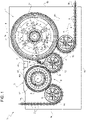
- Number 1 in Figure 1 indicates as a whole a receptacle treatment machine, in particular an automatic receptacle treatment machine, for the treatment of receptacles 2 (see Figure 2 ), such as bottles, jars, vessels, containers or the like, in particular being made of base components, like glass, paper or cardboard, plastics, aluminum, steel, and composites.
- receptacles 2 such as bottles, jars, vessels, containers or the like, in particular being made of base components, like glass, paper or cardboard, plastics, aluminum, steel, and composites.
- receptacle treatment machine 1 may be configured to:
- receptacle treatment machine 1 may be configured to fill and/or apply closures onto receptacles 2 within a sterile and/or aseptic environment.
- receptacle treatment machine 1 comprises at least:
- receptacle treatment machine 1 may comprise a conditioning unit configured to control an ambient condition, such as temperature and/or humidity and/or sterility and/or cleanliness and/or an airflow (direction), within inner environment 4.
- a conditioning unit configured to control an ambient condition, such as temperature and/or humidity and/or sterility and/or cleanliness and/or an airflow (direction), within inner environment 4.
- receptacle treatment machine 1 also comprises a quality control apparatus 9 configured to execute operations allowing to determine the cleanliness (sterility) within inner environment 4, in particular during operation of receptacle treatment machine 1 (i.e. during the treatment of receptacles 2).
- isolation chamber 3 comprises an inlet 13 and an outlet 14 designed to allow for respectively feeding and discharging receptacles 2 to and from inner environment 4.
- isolation chamber 3 may comprise a plurality of walls 15 (only some shown) delimiting inner environment 4, in particular delimiting inner environment 4 from six faces, and carrying inlet 13 and outlet 14.
- one or more walls 15 define a base (bottom portion) of receptacle treatment machine 1, in particular of isolation chamber 3.
- conveying apparatus 6 may be configured to advance receptacles 2 from inlet 13 to outlet 14, and in particular is designed to receive receptacles 2 at inlet 13 and to discharge receptacles 2 at outlet 14.
- conveying apparatus 6 may comprise one or more star wheels 16, in the example shown three, and/or one or more conveying carousels 17, in the example shown two, each star wheel 16 and each conveying carousel 17 being rotatable around a respective rotation axis A, in particular having a vertical orientation, and each one being configured to advance receptacles 2 along a respective (arc-shaped) portion of advancement path P.
- one conveying carousel 17 is associated to filling apparatus 7 and defines (at least partially) filling portion P1 and/or one conveying carousel 17 is associated to capping apparatus 8 and defines (at least partially) capping portion P2.
- At least one star wheel 16 is arranged upstream of each conveying carousel 17 and at least one star wheel 16 is arranged downstream of one respective conveying carousel 17 along advancement path P.
- filling apparatus 7 may comprise a plurality of filling units (not shown and known as such) arranged within inner environment 4 and configured to fill receptacles 2 with the pourable product during advancement of receptacles 2 along filling portion P1.
- the filling units are arranged on the respective conveying carousel 17, in particular the filling units being equally spaced about the respective rotation axis A.
- each filling unit comprises a retaining element, such as a gripping element or a pedestal, designed to retain one respective receptacle 2 during advancement along the filling portion P1 and a filling valve designed to direct the pourable product into the respective receptacle 2 during its advancement along filling portion P1.
- a retaining element such as a gripping element or a pedestal
- each capping apparatus 8 may comprise a plurality of capping units (known as such) configured retain receptacles 2 and to apply (and fasten) the closures on receptacles 2 during their advancement along capping portion P2.
- the capping units are arranged on the respective conveying carousel 17, and in particular are equally spaced about the respective rotation axis A.
- each capping unit may comprise a respective retaining element, such as a gripping element or a pedestal, configured to retain one respective receptacle 2 during advancement along the capping portion P2 and a respective capping head 18 configured to apply and to fasten one respective closure on the respective receptacle 2.
- a respective retaining element such as a gripping element or a pedestal
- quality control apparatus 9 comprises a robot 19 arranged within inner environment 4.
- robot 19 is configured to operate in one or more operating configurations (the operating configurations being distinct from one another) so as to collect samples within inner environment 4 for determining the cleanliness and/or sterility within inner environment 4.
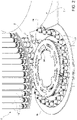
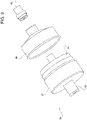
- robot 19 is designed to manipulate and/or operate swab devices 20 and/or fluid filtering and/or sampling devices 21 and/or sampling dishes 22 (such as Petri dishes), in particular for collecting samples designed to determine information about possible contaminations (e.g. due to the presence of microbes, bacteria, viruses or any other contaminations) within inner environment 4.
- swab devices 20 and/or fluid filtering and/or sampling devices 21 and/or sampling dishes 22 such as Petri dishes
- each swab device 20 may allow to take a sample by swapping over a surface arranged within inner environment 4.
- each swab device 20 may comprise a probe head 23, e.g. comprising cotton or similar, designed to be put into contact with a surface and to be guided over the surface for possibly collecting material present on the surface.
- a probe head 23 e.g. comprising cotton or similar, designed to be put into contact with a surface and to be guided over the surface for possibly collecting material present on the surface.
- each swab device 20 may also comprise a tubular receptacle 24 designed to host and protect the respective probe head 23, in particular prior and after swabbing of the respective probe head 23.
- each swab device 20 may also comprise a gripping portion 25 and a rod portion 26 carrying the respective probe head 23 at a first end and the respective gripping portion 26 at a second end.
- each swab device 20 may comprise a securing assembly (e.g. a screwing mechanism) for (removably and/or reversibly) securing the respective gripping portion 25 to the respective tubular receptacle 24.
- a securing assembly e.g. a screwing mechanism
- swab devices 20 may be based on the detection of adenosine triphosphate (ATP).
- ATP adenosine triphosphate
- each fluid filtering and/or sampling device 21 is designed to be fluidically coupled to a fluidic line within inner environment 4 so as to filter and/or sample the fluid being present within the fluidic line.
- a fluidic line may provide for a liquid (e.g. sterile water) or a gas (e.g. sterile air) to be used during operation of receptacle treatment machine 1.
- each fluid filtering and/or sampling device 21 may be designed to at least retain contaminations possibly present within the filtered and/or sampled fluid.
- each sampling dish 22 comprises a main dish 27 and a cover 28 (removably) placed and/or placeable onto main dish 27.
- each sample dish 22, in particular the respective main dish 27, may contain a culture media.
- robot 19 may be placed within inner environment 4 adjacent to filling apparatus 7 and/or capping apparatus 8, in particular so that the sampling can be executed at and/or adjacent to filling apparatus 7 and/or capping apparatus 8.
- robot 19 could be fixedly arranged (i.e. its position within inner environment 4 is not modifiable) or is moveable so as to modify, in use, the position of robot 19 within inner environment 4.
- robot 19 could comprise and/or could be coupled to an actuating unit for modifying its position within isolation chamber 3 and/or inner environment 4.
- the actuating unit could comprise a rail system and/or could be based on magnetic elevation and/or wheels coupled to robot 19 and/or defining a tracked robot 19.
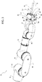
- robot 19 comprises at least a manipulating device 34 having a robotic arm 35 and an end effector unit 36 connected to the robotic arm 35.
- robot 19 and/or manipulating device 34 could comprise a control unit configured to control operation of robotic arm 35 and/or end effector unit 36.
- robot 19 could comprise a base carrying robotic arm 35.
- robotic arm 35 may be configured to control movement of end effector unit 36 in a three-dimensional space and/or may actuate a rotation of end effector unit 36 around a rotation axis B.
- robotic arm 35 may be of the anthropomorphic-type.
- robotic arm 35 may comprise at least a wrist portion 37 carrying end effector unit 36.
- end effector unit 36 may be rotatably mounted to wrist portion 37 allowing for rotation around rotation axis B.
- robotic arm 35 comprises an electrical motor arranged within wrist portion 37, being operatively coupled to end effector unit 36 and configured to actuate rotation of end effector unit 36 around rotation axis B.
- robotic arm 35 may comprise:
- forearm portion 38 and wrist portion 37 and/or forearm portion 38 and elbow portion 39 and/or elbow portion 39 and biceps portion 40 and/or biceps portion 40 and should portion 41 and/or shoulder portion 41 and tower portion 42 are moveable, in particular angularly moveable, with respect to one another.
- robotic arm 35 comprises a plurality of electrical motors designed to actuate the relative (angular) movements between forearm portion 38 and wrist portion 37 and/or forearm portion 38 and elbow portion 39 and/or elbow portion 39 and biceps portion 40 and/or biceps portion 40 and should portion 41 and/or shoulder portion 41 and tower portion 42.
- robot 19 in particular manipulating device 34, even more particular end effector unit 36, is controllable into at least one, preferentially in all, of the following operating conditions:
- robot 19 in particular manipulating device 34, even more particular end effector unit 36 can be repeatedly controlled in the first and/or second and/or third operating condition.
- robot 19, in particular manipulating device 34, even more particular end effector unit 36 can be repeatedly (and in varying orders) controlled between the first, second and third operating condition.
- control unit may be configured to control operation of robotic arm 35 and/or end effector unit 36 in dependence of the specific operating condition within which robot 19, in particular manipulating device 34, even more particular end effector unit 36, is controlled.
- control unit is configured to control robotic arm 35 and/or end effector unit 36 such:
- receptacle treatment machine 1 may comprise a lock housing 43 having and/or delimiting a lock space 44.
- lock housing 43 is designed to allow a discharging of (used) swap devices 20 and/or (used) fluid filter and/or sampling devices 21 and/or (used) sampling dishes 22 from isolation chamber 3 during operation of receptacle treatment machine 1, in particular without the need to interrupt operation of receptacle treatment machine 1 and to maintain the cleanliness and/or sterility of inner environment 4.
- lock housing 43 comprises a first opening and a second opening allowing a fluidic connection of lock space 44 with respectively inner environment 4 and outer environment 5.
- lock housing 43 also comprises means associated to the first and/or second opening so as to guarantee that during operation of receptacle treatment machine 1 contaminations may not enter from outer environment 5 into inner environment 4.
- Such means may comprise closing elements and/or gas (air) blades and/or directed gas (air) flows.
- control unit may be configured to control robotic arm 35 and/or end effector unit 36 such that the manipulation of the at least one swap device 20 comprises one or more of the following (consecutive) steps:
- control unit may be configured to control robotic arm 35 and/or end effector unit 36 such that the manipulation of the at least one fluid filtering and/or sampling device 21 comprises one or more of the following (consecutive) steps:
- control unit may be configured to control robotic arm 35 and/or end effector unit 36 such that the manipulation of the at least one sampling dish 22 comprises one or more of the following (consecutive) steps:
- robotic arm 35 and/or end effector unit 36 may, in use, be controlled such to retain swap device 20 or fluid filtering and/or sampling device 21 and/or sampling dish 22 within inner environment 4.
- swap device 20 or fluid filtering and/or sampling device 21 or sampling dish 22 is/are discharged from inner environment 4 only after stopping operation of receptacles treatment machine 1.
- end effector unit 36 may comprise at least a gripping assembly 50 configured to selectively (and directly or indirectly) grip and/or carry swab device 20 and/or fluid filtering and/or sampling device 21.
- end effector unit 36 comprises a support structure 51, in particular rotatably mounted to wrist portion 37.
- support structure 51 carries at least gripping assembly 50.
- gripping assembly 50 comprises at least a first clamp element 52 and a second clamp element 53, which are configured to (directly or indirectly) grip in collaboration with one another swab device 20 and/or fluid filtering and/or sampling device 21.
- first clamp element 52 is (non-moveably and/or integrally) fixed to support structure 51 and second clamp element 53 is moveable with respect to first clamp element 52, in particular second clamp element 53 is moveably coupled to support structure 51.
- second clamp element 53 is moveable between at least an active position and a rest position at which first clamp element 52 and second clamp element 53 are adapted to respectively execute a clamping step and a releasing or receiving step.
- gripping assembly 50 is, in particular clamp elements 52 and 53 are, designed to engage and clamp gripping portions 25 for gripping the respective swab devices 20.
- clamp elements 52 and 53 are adapted to clamp gripping portion 25 with second clamp element 53 being in the active position and to release or receive gripping portion 25 with second clamp element 53 being in the rest position.
- robot 19, in particular the manipulating device 34 may comprise a support housing 54 having an inner space housing or designed to house one respective fluid filtering and/or sampling device 21.
- support housing 54 allows to facilitate the gripping and handling of fluid filtering and/or sampling device 21 by gripping assembly 50, in particular by clamp elements 52 and 53.
- support housing 54 may comprise a gripping portion 55 designed to be clamped in between first and second clamp elements 52 and 53 such that gripping assembly 50 carries support housing 54 together with fluid filtering and/or sampling device 21.
- support housing 43 is designed to allow gripping assembly 50 to indirectly carry fluid filter and/or sampling device 21.
- support housing 43 may also comprise a coupling portion 56 designed to couple to one or more fluidic lines of receptacle treatment machine 1 and to establish the fluidic connection between fluid filtering and/or sampling device 21 and the fluidic line.
- support housing 43 may comprise a first housing portion 57 and a second housing portion 58 being removably connected or connectable with one another and delimiting the inner space of support housing 43.
- housing portion 57 carries gripping portion 55 and housing portion 58 carries coupling portion 56.
- gripping assembly 50 is, in particular clamp elements 52 and 53 are, also designed to engage and clamp gripping portion 55 for gripping the respective support housing 54.
- clamp elements 52 and 53 are adapted to clamp gripping portion 55 with second clamp element 53 being in the active position and to release or receive gripping portion 55 with second clamp element 53 being in the rest position.
- end effector unit 36 comprises a support device 62 configured to at least indirectly (in other words, directly or indirectly) carry one sampling dish 22.
- robot 19, in particular manipulating device 34 may comprise a support platform 63 designed to support and carry sampling dish 22.
- support platform 63 comprises a cavity for receiving and hosting a portion of sampling dish 22, in particular main dish 27, and in particular a gasket 64, in the example shown an O-ring, for fixing sampling dish 22 within the cavity.
- support device 62 is designed to carry support platform 63 for indirectly carrying sampling dish 62.
- support platform 63 is designed such to leave an interspace 73 between support platform 63 and cover 28. As will be apparent from further below such interspace 73 may facilitate removing or placing cover 28 from or to main dish 27.
- support platform 63 comprises (or even consists) of a ferromagnetic or magnetic or paramagnetic material.
- receptacle treatment machine 1 may comprise one or more magnets positioned so as to define placing stations at which, in use, support platform 63 should be placed together with the respective sampling dish 22.
- the magnets are designed to interact with support platform 63 so as to exert a retaining force on support platform 63.
- the magnets may be placed within outer environment 5 (and support platform 63 and the respective magnet are separated by means of a relative portion of walls 15).
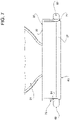
- support device 62 comprises a fork element 65 (having two spaced apart arms), in particular fixedly (non-moveably and/or integrally) mounted to support structure 51 and an auxiliary support element 66 moveable with respect to fork element 65 (and support structure 51) between an operative position at which auxiliary support element 66 is configured to support in collaboration with fork element 65 sampling dish 22, e.g. by supporting support platform 63, and a release position at which auxiliary support element 66 is designed to be retracted from sampling dish 22, e.g. by retracting from support platform 63 (so as to allow receiving or releasing sampling disk 22 and/or support platform 63).
- auxiliary support element 66 moveable with respect to fork element 65 (and support structure 51) between an operative position at which auxiliary support element 66 is configured to support in collaboration with fork element 65 sampling dish 22, e.g. by supporting support platform 63, and a release position at which auxiliary support element 66 is designed to be retracted from sampling dish 22, e.g. by
- fork element 65 delimits a cavity 67 designed to receive at least partially sampling disk 22 and/or support platform 63.
- support device 62 comprises an engagement surface 68 configured to carry sampling disk 22 and/or support platform 63.
- fork element 65 and auxiliary support element 66 comprise respectively a first surface portion 69 and a second surface portion 70 of engagement surface 68.
- engagement surface 68 defines, in particular first surface portion 69 and second surface portion 70 define, at least three rest points for carrying sampling disk 22 and/or support platform 63 and with auxiliary support element 66 being in the operative position.
- engagement surface 68 protrudes into and/or towards cavity 67 at least with auxiliary support element 66 being in the operative position.
- support platform 63 comprises an undercut 71 for interacting with engagement surface 68.
- support device 62 in particular fork element 65 and auxiliary support element 66, even more particular engagement surface 68, may also be configured to engage with and to carry cover 28 so as to allow for removing and placing of cover from and to main dish 27.
- interspace 73 allows to receive engagement surface 68 thereby facilitating the process of removing and placing cover 28 from and to main dish 27.
- end effector unit 36 may also comprise a clamping element 72 configured to engage cover 28 and to collaborate with engagement surface 68 so as to exert a clamping fore, in particular thereby clamping support platform 63 and/or sampling dish 22 between clamping element 72 and engagement surface 68.
- end effector unit 36 may comprise:
- angular movement of support arm 76 around rotation axis C allows controlling second clamp element 53 and auxiliary support element 66 between respectively the active and the rest position and the operative position and the release position.
- support arm 76, clamp element 53 and auxiliary support element 66 are realized in a single piece.
- actuation device 77 comprises a first shaft 78 (fixedly) connected with support arm 76 by means of a connection element 79 (of end effector unit 36) and defining rotation axis C.
- shaft 78 extends along and is rotatable around rotation axis C.
- rotation axis C and support arm 76 may be substantially parallel to one another.
- rotation axis C may be transversally, in particular perpendicularly, oriented with respect to fork element 65.
- connection element 79 is transversally arranged both to shaft 78 and to support arm 76.
- connection element 79 may be integral to support arm 76.
- clamping element 72 is connected to (a terminal portion of) shaft 78.
- clamping element 72 is designed to at least partially connect connection element 79 and thereby support arm 76 to shaft 78.
- actuation device 77 may comprise an electrical motor 80 having a drive axle 81 rotatable around a rotation axis E being not parallel and/or being transversal, in particular perpendicular, to rotation axis C, and being operatively coupled to shaft 78 such that rotation of drive axle 81 around rotation axis E actuates a rotation of shaft 78 around rotation axis C.
- actuation device 77 may comprise a gear assembly 82 operatively coupling shaft 78 and drive axle 81 with one another.
- support structure 51 comprises a housing 83 within which electrical motor 80, and in particular gear assembly 82 and a portion of shaft 78, is/are placed.
- housing 83 fixedly carries clamping element 52.
- the support structure 51 defines or comprises the housing 83.
- the first clamp element 52 is constrained to the housing 83.
- the first clamp element 52 is constrained or fixed to the housing 83.
- the first clamp element 52 is located in front of the housing 83 along a direction which is not parallel to the rotation axis C of the support arm 76 and which is not parallel to the rotation axis E of the motor 80.
- Said direction not parallel to rotation axis C of support arm 76 is a direction transversal with respect to both the rotation axis C of the support arm 76 and the rotation axis E of the motor 80.
- the fork element 65 is located below the housing 83 along a direction which is parallel to the rotation axis C of the support arm 76 and which is not parallel to the rotation axis E of the motor 80.
- support structure 51 may comprise a coupling structure 84 rotatably (around rotation axis B) connected to wrist portion 37 and carrying housing 83 and fork element 65.
- receptacle treatment apparatus 1 fills receptacles 2 with the pourable product and/or applies and fastens closures on receptacles 2.
- conveying apparatus 6 advances receptacles 2 along advancement path P
- filling apparatus 7 fills receptacles 2 with the pourable product during their advancement along filling portion P1
- capping apparatus 8 applies and fastens the closures on receptacles 2 during their advancement along capping portion P2.
- inner environment 4 being a clean and/or sterile and/or aseptic environment.
- robot 19, in particular manipulating device 34, even more particular end effector unit 36 is (selectively) controlled into at least one of the first, second and third operating condition.
- robot 19, in particular end effector unit 36 is controlled at least once into the first operating condition, at least once into the second operating condition and at least once into the third operating condition.
- robot 19 in particular manipulating device 34, even more particular end effector unit 36, is repeatedly controlled into the first, second and third operating condition so as to obtain samples at different times during the operation of receptacle treatment apparatus 1.
- robot 19 in particular manipulating device 34, even more particular end effector unit 36, is configured to:
- control unit may control operation of robotic arm 35 and/or end effector unit 36 in dependence of the specific operating condition within which robot 19, in particular end effector unit 36, is controlled.
- one or more (new) swab devices 20, fluid filtering devices 21 and sampling dishes 22 are placed within inner environment 4, in particular prior to operation of receptacle treatment apparatus 1.
- robotic arm 35 and/or end effector unit 36 are in more detail.
- robotic arm 35 and/or end effector unit 36 are with robot 19, in particular end effector unit 36, controlled such that the manipulation of the at least one swap device 20 comprises one or more of the following (consecutive) steps:
- a step of retaining swab device 20 within inner environment 4 could be executed.
- gripping assembly 50 grips gripping portion 25.
- clamping element 53 is moved (by rotation of support arm 76 around rotation axis C, from the rest position to the active position such that clamping elements 52 and 53 clamp gripping portion 25 between one another.
- the rotation of support arm 76 is activated by actuation device 77.
- robotic arm 35 is moved, while gripping assembly 50 continues retaining gripping portion 25.
- gripping assembly 50 it may also be necessary to actuate a rotation of end effector unit 36 around rotation axis B during the one or more of the steps of engaging and/or extracting and/or moving and/or placing.
- control unit may control robotic arm 35 and/or end effector unit 36 such that the manipulation of the at least one fluid filtering and/or sampling device 21 comprises one or more of the following (consecutive) steps:
- a step of retaining filtering and/or sampling device 21 within inner environment 4 could be executed.
- gripping assembly 50 clamps gripping portion 55 so as to retain support housing 54 containing fluid filtering and/sampling device 21. Even more preferentially, clamping element 53 is moved (by rotation of support arm 76 around rotation axis C, from the rest position to the active position such that clamping elements 52 and 53 clamp gripping portion 55 between one another. Preferentially, the rotation of support arm 76 is activated by actuation device 77.
- control unit may control robotic arm 35 and/or end effector unit 36 such that the manipulation of the at least one sampling dish 22 comprises one or more of the following (consecutive) steps:
- a step of retaining sampling dish 22 within inner environment 4 could be executed.
- end effector unit 36 approaches sampling device 22 and/or support platform 63, in particular with auxiliary support element 66 being in the releasing position. Furthermore, once first surface portion 69 contacts support platform 63, auxiliary support element 66 is moved to the operative position.
- robot arm 35 moves end effector unit 36 so as to place sampling dish 22 and/or support platform 63 onto the support surface, preferentially at a placing station at which sampling dish 22 and/or support platform 63 are fastened by means of a magnetic force (resulting from the interaction with the respective magnet).
- support device 62 is detached from sampling dish 22 and/or support platform 63. Even more particular, auxiliary support element 66 is controlled into the releasing position followed by retracting support device 62.
- support device 62 engages cover 28 and then end effector unit 36 is moved by robotic arm 35 away from main dish 27. Even more particular, at first surface portion 69 is positioned within interspace 73 and then auxiliary support element 66 is moved into the operative position.
- support device 62 carries cover 28 and then end effector unit 36 is moved by robotic arm 35 so as to approach main dish 27.
- engagement surface 68 carries cover 28 and once cover 28 is placed on main dish 27 auxiliary support element 66 is moved into the release position; afterwards, surface portion 69 is removed out of interspace 73.
- robotic arm 35 moves and/or end effector unit 36 rotates around rotation axis B. Furthermore, end effector unit 36 releases swap device 20 or fluid filtering and/or sampling device 21 or sampling dish 22 within lock space 44.
- a step of collecting and a step of analyzing are executed.
- the swap device 20 and/or fluid filtering and/or sampling device 21 and/or sampling dish 22 is/are removed from lock housing 43 and during the step of analyzing the swap device 20 and/or fluid filtering and/or sampling device 21 and/or sampling dish 22 is/are analyzed so as to determine the cleanliness within inner environment 4.
- robot 19 allows to analyze the cleanliness and/or sterility within isolation chamber 3 during operating of receptacle treatment machine 1 by manipulating swap device(s) 20 and/or fluid filtering and/or sampling device(s) 21 and/or sampling dish(es) 22. Even more particular, robot 19 can execute different test procedures.
- End effector unit 36 comes along with a compact design.
- End effector unit 36 has a single electrical motor 80, which can actuate a rotation of support arm 76, which allows to control both gripping assembly 50 and support device 62.
- a further advantage resides in that receptacle treatment machine 1 has lock housing 43 allowing to discharge swap device(s) 20 and/or fluid filtering and/or sampling device(s) 21 and/or sampling dish(es) 22 out of inner environment 4 without compromising the cleanliness of inner environment 4.
Landscapes
- Life Sciences & Earth Sciences (AREA)
- Health & Medical Sciences (AREA)
- Engineering & Computer Science (AREA)
- Chemical & Material Sciences (AREA)
- General Health & Medical Sciences (AREA)
- Biochemistry (AREA)
- Zoology (AREA)
- Wood Science & Technology (AREA)
- Bioinformatics & Cheminformatics (AREA)
- Organic Chemistry (AREA)
- Analytical Chemistry (AREA)
- General Physics & Mathematics (AREA)
- Physics & Mathematics (AREA)
- Pathology (AREA)
- Immunology (AREA)
- Robotics (AREA)
- Biomedical Technology (AREA)
- Molecular Biology (AREA)
- Genetics & Genomics (AREA)
- Biotechnology (AREA)
- Sustainable Development (AREA)
- General Engineering & Computer Science (AREA)
- Microbiology (AREA)
- Mechanical Engineering (AREA)
- Hydrology & Water Resources (AREA)
- Epidemiology (AREA)
- Public Health (AREA)
- Clinical Laboratory Science (AREA)
- Food Science & Technology (AREA)
- Sampling And Sample Adjustment (AREA)
Priority Applications (2)
| Application Number | Priority Date | Filing Date | Title |
|---|---|---|---|
| EP20205372.4A EP3991925A1 (fr) | 2020-11-03 | 2020-11-03 | Dispositif de manipulation pour un robot, robot doté d'un dispositif de manipulation pour une machine de traitement de récipient, machine de traitement de récipient dotée d'un robot et procédé de contrôle de qualité |
| PCT/EP2021/075215 WO2022096184A1 (fr) | 2020-11-03 | 2021-09-14 | Dispositif de manipulation pour un robot, robot ayant un dispositif de manipulation pour une machine de traitement de réceptacle, machine de traitement de réceptacle ayant un robot et procédé de contrôle de qualité |
Applications Claiming Priority (1)
| Application Number | Priority Date | Filing Date | Title |
|---|---|---|---|
| EP20205372.4A EP3991925A1 (fr) | 2020-11-03 | 2020-11-03 | Dispositif de manipulation pour un robot, robot doté d'un dispositif de manipulation pour une machine de traitement de récipient, machine de traitement de récipient dotée d'un robot et procédé de contrôle de qualité |
Publications (1)
| Publication Number | Publication Date |
|---|---|
| EP3991925A1 true EP3991925A1 (fr) | 2022-05-04 |
Family
ID=73059526
Family Applications (1)
| Application Number | Title | Priority Date | Filing Date |
|---|---|---|---|
| EP20205372.4A Withdrawn EP3991925A1 (fr) | 2020-11-03 | 2020-11-03 | Dispositif de manipulation pour un robot, robot doté d'un dispositif de manipulation pour une machine de traitement de récipient, machine de traitement de récipient dotée d'un robot et procédé de contrôle de qualité |
Country Status (2)
| Country | Link |
|---|---|
| EP (1) | EP3991925A1 (fr) |
| WO (1) | WO2022096184A1 (fr) |
Families Citing this family (1)
| Publication number | Priority date | Publication date | Assignee | Title |
|---|---|---|---|---|
| CN115184094B (zh) * | 2022-07-11 | 2023-06-13 | 苏州大学附属儿童医院 | 一种尿液盛装器及配套的泌外尿检分析处理系统 |
Citations (7)
| Publication number | Priority date | Publication date | Assignee | Title |
|---|---|---|---|---|
| US4626013A (en) * | 1984-12-11 | 1986-12-02 | General Electric Company | Dual axis gripper |
| US5823592A (en) * | 1996-06-28 | 1998-10-20 | Kalidindi; Sanyasi Raju | Flexible swabbing tool |
| US20040185521A1 (en) * | 2003-03-20 | 2004-09-23 | Shigeru Yoshida | Microorganism sampling method and microorganism sampling device |
| EP2818284A1 (fr) * | 2013-06-24 | 2014-12-31 | Kabushiki Kaisha Yaskawa Denki | Robot, procédé de production de robot et protection d'outil |
| US20180133893A1 (en) * | 2015-05-07 | 2018-05-17 | Yamato Scientific Co., Ltd. | Sample treatment system |
| US20190331701A1 (en) * | 2018-04-30 | 2019-10-31 | Lonza Limited | System and Method for Environmental Monitoring |
| US20210136722A1 (en) * | 2019-11-04 | 2021-05-06 | Particle Measuring Systems, Inc. | Mobile monitoring device for controlled contamination areas |
Family Cites Families (1)
| Publication number | Priority date | Publication date | Assignee | Title |
|---|---|---|---|---|
| IT201900000166A1 (it) * | 2019-01-08 | 2020-07-08 | Ima Spa | Apparato e metodo per la gestione automatizzata di dispositivi rivelatori di carica batterica. |
-
2020
- 2020-11-03 EP EP20205372.4A patent/EP3991925A1/fr not_active Withdrawn
-
2021
- 2021-09-14 WO PCT/EP2021/075215 patent/WO2022096184A1/fr not_active Ceased
Patent Citations (7)
| Publication number | Priority date | Publication date | Assignee | Title |
|---|---|---|---|---|
| US4626013A (en) * | 1984-12-11 | 1986-12-02 | General Electric Company | Dual axis gripper |
| US5823592A (en) * | 1996-06-28 | 1998-10-20 | Kalidindi; Sanyasi Raju | Flexible swabbing tool |
| US20040185521A1 (en) * | 2003-03-20 | 2004-09-23 | Shigeru Yoshida | Microorganism sampling method and microorganism sampling device |
| EP2818284A1 (fr) * | 2013-06-24 | 2014-12-31 | Kabushiki Kaisha Yaskawa Denki | Robot, procédé de production de robot et protection d'outil |
| US20180133893A1 (en) * | 2015-05-07 | 2018-05-17 | Yamato Scientific Co., Ltd. | Sample treatment system |
| US20190331701A1 (en) * | 2018-04-30 | 2019-10-31 | Lonza Limited | System and Method for Environmental Monitoring |
| US20210136722A1 (en) * | 2019-11-04 | 2021-05-06 | Particle Measuring Systems, Inc. | Mobile monitoring device for controlled contamination areas |
Also Published As
| Publication number | Publication date |
|---|---|
| WO2022096184A1 (fr) | 2022-05-12 |
Similar Documents
| Publication | Publication Date | Title |
|---|---|---|
| EP1460126B1 (fr) | Méthode de prélèvement de microorganismes et dispositif de prélèvement de microorganismes | |
| US10684301B2 (en) | Sample processing system for processing biological samples | |
| EP2938545B1 (fr) | Machine et procédé de remplissage de récipients | |
| US8869496B2 (en) | Device for filling containers | |
| US6470922B2 (en) | Bottling plant for bottling carbonated beverages | |
| CN112678223A (zh) | 饮料灌装设备中的自动套件更换 | |
| JP2003095428A (ja) | 非円形容器検査装置及び方法 | |
| US20060088443A1 (en) | Apparatus having improved gantry assembly suitable for use in a laboratory environment | |
| MX2009002318A (es) | Metodo para la inspeccion de botellas o envases similares y estacion de medicion para un trayecto de inspeccion o control para botellas o envases similares. | |
| US6852288B2 (en) | System for multiple sterile sample collection and isolation | |
| WO2022096184A1 (fr) | Dispositif de manipulation pour un robot, robot ayant un dispositif de manipulation pour une machine de traitement de réceptacle, machine de traitement de réceptacle ayant un robot et procédé de contrôle de qualité | |
| JP2014020779A (ja) | 核酸抽出装置 | |
| CA2259117A1 (fr) | Appareil et procede de prelevement d'echantillons liquides | |
| JPH07191045A (ja) | ねじキャップにより密封された瓶から液体サンプルを採取する組立体 | |
| CN116380523A (zh) | 一种智能抽样装置 | |
| US8297151B1 (en) | Apparatus for opening and closing a specimen vial | |
| EP4186851A1 (fr) | Bras robotique permettant de manipuler une tête de recouvrement, robot comprenant le bras robotique et appareil d'emballage comprenant le robot | |
| EP4060350B1 (fr) | Appareil de retrait de capuchon de fermeture de récipient d'échantillons de laboratoire et système d'automatisation de laboratoire | |
| EP3995818B1 (fr) | Machine de traitement d'article comportant un système d'inspection | |
| EP4410950B1 (fr) | Dispositif gravitationnel de séparation de liquides, dispositif de passage de cellules doté de celui-ci et procédé de passage de cellules | |
| WO2026027447A1 (fr) | Dispositif automatisé de retrait et de manipulation de bouchon pour contenants à bouchon fileté ou enfiché et système de manipulation de contenant pourvu de celui-ci | |
| US12606791B2 (en) | Gravitational liquid-splitting device, cell passaging device with the same, and cell passaging method | |
| KR20260046731A (ko) | 바이러스 농축 자동화 장치 및 방법 | |
| JP2025127388A (ja) | 内容物充填装置 | |
| CN119043855A (zh) | 自动针式过滤设备 |
Legal Events
| Date | Code | Title | Description |
|---|---|---|---|
| PUAI | Public reference made under article 153(3) epc to a published international application that has entered the european phase |
Free format text: ORIGINAL CODE: 0009012 |
|
| STAA | Information on the status of an ep patent application or granted ep patent |
Free format text: STATUS: THE APPLICATION HAS BEEN PUBLISHED |
|
| AK | Designated contracting states |
Kind code of ref document: A1 Designated state(s): AL AT BE BG CH CY CZ DE DK EE ES FI FR GB GR HR HU IE IS IT LI LT LU LV MC MK MT NL NO PL PT RO RS SE SI SK SM TR |
|
| STAA | Information on the status of an ep patent application or granted ep patent |
Free format text: STATUS: REQUEST FOR EXAMINATION WAS MADE |
|
| 17P | Request for examination filed |
Effective date: 20220530 |
|
| RBV | Designated contracting states (corrected) |
Designated state(s): AL AT BE BG CH CY CZ DE DK EE ES FI FR GB GR HR HU IE IS IT LI LT LU LV MC MK MT NL NO PL PT RO RS SE SI SK SM TR |
|
| REG | Reference to a national code |
Ref country code: DE Ref legal event code: R079 Free format text: PREVIOUS MAIN CLASS: B25J0015000000 Ipc: C12M0001120000 |
|
| RIC1 | Information provided on ipc code assigned before grant |
Ipc: B67C 3/22 20060101ALI20240305BHEP Ipc: G01N 1/22 20060101ALI20240305BHEP Ipc: G01N 1/20 20060101ALI20240305BHEP Ipc: C12M 1/30 20060101ALI20240305BHEP Ipc: C12M 1/00 20060101ALI20240305BHEP Ipc: G01N 35/00 20060101ALI20240305BHEP Ipc: G01N 1/10 20060101ALI20240305BHEP Ipc: G01N 1/02 20060101ALI20240305BHEP Ipc: B25J 11/00 20060101ALI20240305BHEP Ipc: B25J 15/00 20060101ALI20240305BHEP Ipc: C12M 1/12 20060101AFI20240305BHEP |
|
| GRAP | Despatch of communication of intention to grant a patent |
Free format text: ORIGINAL CODE: EPIDOSNIGR1 |
|
| STAA | Information on the status of an ep patent application or granted ep patent |
Free format text: STATUS: GRANT OF PATENT IS INTENDED |
|
| INTG | Intention to grant announced |
Effective date: 20240415 |
|
| STAA | Information on the status of an ep patent application or granted ep patent |
Free format text: STATUS: THE APPLICATION IS DEEMED TO BE WITHDRAWN |
|
| 18D | Application deemed to be withdrawn |
Effective date: 20240817 |