EP3991973A1 - Bildaufzeichnungsvorrichtung - Google Patents
Bildaufzeichnungsvorrichtung Download PDFInfo
- Publication number
- EP3991973A1 EP3991973A1 EP20832053.1A EP20832053A EP3991973A1 EP 3991973 A1 EP3991973 A1 EP 3991973A1 EP 20832053 A EP20832053 A EP 20832053A EP 3991973 A1 EP3991973 A1 EP 3991973A1
- Authority
- EP
- European Patent Office
- Prior art keywords
- information
- type
- request
- controller
- status information
- Prior art date
- Legal status (The legal status is an assumption and is not a legal conclusion. Google has not performed a legal analysis and makes no representation as to the accuracy of the status listed.)
- Granted
Links
Images


Classifications
-
- B—PERFORMING OPERATIONS; TRANSPORTING
- B41—PRINTING; LINING MACHINES; TYPEWRITERS; STAMPS
- B41J—TYPEWRITERS; SELECTIVE PRINTING MECHANISMS, i.e. MECHANISMS PRINTING OTHERWISE THAN FROM A FORME; CORRECTION OF TYPOGRAPHICAL ERRORS
- B41J2/00—Typewriters or selective printing mechanisms characterised by the printing or marking process for which they are designed
- B41J2/005—Typewriters or selective printing mechanisms characterised by the printing or marking process for which they are designed characterised by bringing liquid or particles selectively into contact with a printing material
- B41J2/01—Ink jet
- B41J2/17—Ink jet characterised by ink handling
- B41J2/175—Ink supply systems ; Circuit parts therefor
- B41J2/17503—Ink cartridges
- B41J2/17506—Refilling of the cartridge
- B41J2/17509—Whilst mounted in the printer
-
- B—PERFORMING OPERATIONS; TRANSPORTING
- B41—PRINTING; LINING MACHINES; TYPEWRITERS; STAMPS
- B41J—TYPEWRITERS; SELECTIVE PRINTING MECHANISMS, i.e. MECHANISMS PRINTING OTHERWISE THAN FROM A FORME; CORRECTION OF TYPOGRAPHICAL ERRORS
- B41J2/00—Typewriters or selective printing mechanisms characterised by the printing or marking process for which they are designed
- B41J2/005—Typewriters or selective printing mechanisms characterised by the printing or marking process for which they are designed characterised by bringing liquid or particles selectively into contact with a printing material
- B41J2/01—Ink jet
- B41J2/17—Ink jet characterised by ink handling
- B41J2/175—Ink supply systems ; Circuit parts therefor
-
- B—PERFORMING OPERATIONS; TRANSPORTING
- B41—PRINTING; LINING MACHINES; TYPEWRITERS; STAMPS
- B41J—TYPEWRITERS; SELECTIVE PRINTING MECHANISMS, i.e. MECHANISMS PRINTING OTHERWISE THAN FROM A FORME; CORRECTION OF TYPOGRAPHICAL ERRORS
- B41J2/00—Typewriters or selective printing mechanisms characterised by the printing or marking process for which they are designed
- B41J2/005—Typewriters or selective printing mechanisms characterised by the printing or marking process for which they are designed characterised by bringing liquid or particles selectively into contact with a printing material
- B41J2/01—Ink jet
- B41J2/17—Ink jet characterised by ink handling
- B41J2/175—Ink supply systems ; Circuit parts therefor
- B41J2/17503—Ink cartridges
- B41J2/1752—Mounting within the printer
-
- B—PERFORMING OPERATIONS; TRANSPORTING
- B41—PRINTING; LINING MACHINES; TYPEWRITERS; STAMPS
- B41J—TYPEWRITERS; SELECTIVE PRINTING MECHANISMS, i.e. MECHANISMS PRINTING OTHERWISE THAN FROM A FORME; CORRECTION OF TYPOGRAPHICAL ERRORS
- B41J2/00—Typewriters or selective printing mechanisms characterised by the printing or marking process for which they are designed
- B41J2/005—Typewriters or selective printing mechanisms characterised by the printing or marking process for which they are designed characterised by bringing liquid or particles selectively into contact with a printing material
- B41J2/01—Ink jet
- B41J2/17—Ink jet characterised by ink handling
- B41J2/175—Ink supply systems ; Circuit parts therefor
- B41J2/17503—Ink cartridges
- B41J2/17543—Cartridge presence detection or type identification
- B41J2/17546—Cartridge presence detection or type identification electronically
-
- B—PERFORMING OPERATIONS; TRANSPORTING
- B41—PRINTING; LINING MACHINES; TYPEWRITERS; STAMPS
- B41J—TYPEWRITERS; SELECTIVE PRINTING MECHANISMS, i.e. MECHANISMS PRINTING OTHERWISE THAN FROM A FORME; CORRECTION OF TYPOGRAPHICAL ERRORS
- B41J29/00—Details of, or accessories for, typewriters or selective printing mechanisms not otherwise provided for
- B41J29/12—Guards, shields or dust excluders
- B41J29/13—Cases or covers
-
- G—PHYSICS
- G03—PHOTOGRAPHY; CINEMATOGRAPHY; ANALOGOUS TECHNIQUES USING WAVES OTHER THAN OPTICAL WAVES; ELECTROGRAPHY; HOLOGRAPHY
- G03G—ELECTROGRAPHY; ELECTROPHOTOGRAPHY; MAGNETOGRAPHY
- G03G15/00—Apparatus for electrographic processes using a charge pattern
- G03G15/50—Machine control of apparatus for electrographic processes using a charge pattern, e.g. regulating differents parts of the machine, multimode copiers, microprocessor control
- G03G15/5016—User-machine interface; Display panels; Control console
-
- G—PHYSICS
- G03—PHOTOGRAPHY; CINEMATOGRAPHY; ANALOGOUS TECHNIQUES USING WAVES OTHER THAN OPTICAL WAVES; ELECTROGRAPHY; HOLOGRAPHY
- G03G—ELECTROGRAPHY; ELECTROPHOTOGRAPHY; MAGNETOGRAPHY
- G03G15/00—Apparatus for electrographic processes using a charge pattern
- G03G15/55—Self-diagnostics; Malfunction or lifetime display
-
- G—PHYSICS
- G03—PHOTOGRAPHY; CINEMATOGRAPHY; ANALOGOUS TECHNIQUES USING WAVES OTHER THAN OPTICAL WAVES; ELECTROGRAPHY; HOLOGRAPHY
- G03G—ELECTROGRAPHY; ELECTROPHOTOGRAPHY; MAGNETOGRAPHY
- G03G15/00—Apparatus for electrographic processes using a charge pattern
- G03G15/55—Self-diagnostics; Malfunction or lifetime display
- G03G15/553—Monitoring or warning means for exhaustion or lifetime end of consumables, e.g. indication of insufficient copy sheet quantity for a job
- G03G15/556—Monitoring or warning means for exhaustion or lifetime end of consumables, e.g. indication of insufficient copy sheet quantity for a job for toner consumption, e.g. pixel counting, toner coverage detection or toner density measurement
-
- G—PHYSICS
- G06—COMPUTING OR CALCULATING; COUNTING
- G06F—ELECTRIC DIGITAL DATA PROCESSING
- G06F3/00—Input arrangements for transferring data to be processed into a form capable of being handled by the computer; Output arrangements for transferring data from processing unit to output unit, e.g. interface arrangements
- G06F3/12—Digital output to print unit, e.g. line printer, chain printer
- G06F3/1201—Dedicated interfaces to print systems
- G06F3/1202—Dedicated interfaces to print systems specifically adapted to achieve a particular effect
- G06F3/1203—Improving or facilitating administration, e.g. print management
-
- G—PHYSICS
- G06—COMPUTING OR CALCULATING; COUNTING
- G06F—ELECTRIC DIGITAL DATA PROCESSING
- G06F3/00—Input arrangements for transferring data to be processed into a form capable of being handled by the computer; Output arrangements for transferring data from processing unit to output unit, e.g. interface arrangements
- G06F3/12—Digital output to print unit, e.g. line printer, chain printer
- G06F3/1201—Dedicated interfaces to print systems
- G06F3/1202—Dedicated interfaces to print systems specifically adapted to achieve a particular effect
- G06F3/1203—Improving or facilitating administration, e.g. print management
- G06F3/1204—Improving or facilitating administration, e.g. print management resulting in reduced user or operator actions, e.g. presetting, automatic actions, using hardware token storing data
-
- G—PHYSICS
- G06—COMPUTING OR CALCULATING; COUNTING
- G06F—ELECTRIC DIGITAL DATA PROCESSING
- G06F3/00—Input arrangements for transferring data to be processed into a form capable of being handled by the computer; Output arrangements for transferring data from processing unit to output unit, e.g. interface arrangements
- G06F3/12—Digital output to print unit, e.g. line printer, chain printer
- G06F3/1201—Dedicated interfaces to print systems
- G06F3/1223—Dedicated interfaces to print systems specifically adapted to use a particular technique
- G06F3/1229—Printer resources management or printer maintenance, e.g. device status, power levels
-
- G—PHYSICS
- G06—COMPUTING OR CALCULATING; COUNTING
- G06F—ELECTRIC DIGITAL DATA PROCESSING
- G06F3/00—Input arrangements for transferring data to be processed into a form capable of being handled by the computer; Output arrangements for transferring data from processing unit to output unit, e.g. interface arrangements
- G06F3/12—Digital output to print unit, e.g. line printer, chain printer
- G06F3/1201—Dedicated interfaces to print systems
- G06F3/1223—Dedicated interfaces to print systems specifically adapted to use a particular technique
- G06F3/1237—Print job management
- G06F3/1253—Configuration of print job parameters, e.g. using UI at the client
-
- G—PHYSICS
- G06—COMPUTING OR CALCULATING; COUNTING
- G06F—ELECTRIC DIGITAL DATA PROCESSING
- G06F3/00—Input arrangements for transferring data to be processed into a form capable of being handled by the computer; Output arrangements for transferring data from processing unit to output unit, e.g. interface arrangements
- G06F3/12—Digital output to print unit, e.g. line printer, chain printer
- G06F3/1201—Dedicated interfaces to print systems
- G06F3/1278—Dedicated interfaces to print systems specifically adapted to adopt a particular infrastructure
- G06F3/1285—Remote printer device, e.g. being remote from client or server
-
- G—PHYSICS
- G06—COMPUTING OR CALCULATING; COUNTING
- G06F—ELECTRIC DIGITAL DATA PROCESSING
- G06F3/00—Input arrangements for transferring data to be processed into a form capable of being handled by the computer; Output arrangements for transferring data from processing unit to output unit, e.g. interface arrangements
- G06F3/12—Digital output to print unit, e.g. line printer, chain printer
- G06F3/1201—Dedicated interfaces to print systems
- G06F3/1278—Dedicated interfaces to print systems specifically adapted to adopt a particular infrastructure
- G06F3/1285—Remote printer device, e.g. being remote from client or server
- G06F3/1286—Remote printer device, e.g. being remote from client or server via local network
-
- G—PHYSICS
- G06—COMPUTING OR CALCULATING; COUNTING
- G06F—ELECTRIC DIGITAL DATA PROCESSING
- G06F3/00—Input arrangements for transferring data to be processed into a form capable of being handled by the computer; Output arrangements for transferring data from processing unit to output unit, e.g. interface arrangements
- G06F3/12—Digital output to print unit, e.g. line printer, chain printer
- G06F3/1201—Dedicated interfaces to print systems
- G06F3/1278—Dedicated interfaces to print systems specifically adapted to adopt a particular infrastructure
- G06F3/1285—Remote printer device, e.g. being remote from client or server
- G06F3/1288—Remote printer device, e.g. being remote from client or server in client-server-printer device configuration
-
- G—PHYSICS
- G06—COMPUTING OR CALCULATING; COUNTING
- G06K—GRAPHICAL DATA READING; PRESENTATION OF DATA; RECORD CARRIERS; HANDLING RECORD CARRIERS
- G06K15/00—Arrangements for producing a permanent visual presentation of the output data, e.g. computer output printers
- G06K15/02—Arrangements for producing a permanent visual presentation of the output data, e.g. computer output printers using printers
- G06K15/10—Arrangements for producing a permanent visual presentation of the output data, e.g. computer output printers using printers by matrix printers
- G06K15/102—Arrangements for producing a permanent visual presentation of the output data, e.g. computer output printers using printers by matrix printers using ink jet print heads
-
- H—ELECTRICITY
- H04—ELECTRIC COMMUNICATION TECHNIQUE
- H04N—PICTORIAL COMMUNICATION, e.g. TELEVISION
- H04N1/00—Scanning, transmission or reproduction of documents or the like, e.g. facsimile transmission; Details thereof
- H04N1/00002—Diagnosis, testing or measuring; Detecting, analysing or monitoring not otherwise provided for
- H04N1/00007—Diagnosis, testing or measuring; Detecting, analysing or monitoring not otherwise provided for relating to particular apparatus or devices
- H04N1/00015—Reproducing apparatus
-
- H—ELECTRICITY
- H04—ELECTRIC COMMUNICATION TECHNIQUE
- H04N—PICTORIAL COMMUNICATION, e.g. TELEVISION
- H04N1/00—Scanning, transmission or reproduction of documents or the like, e.g. facsimile transmission; Details thereof
- H04N1/00002—Diagnosis, testing or measuring; Detecting, analysing or monitoring not otherwise provided for
- H04N1/00071—Diagnosis, testing or measuring; Detecting, analysing or monitoring not otherwise provided for characterised by the action taken
- H04N1/00074—Indicating or reporting
-
- H—ELECTRICITY
- H04—ELECTRIC COMMUNICATION TECHNIQUE
- H04N—PICTORIAL COMMUNICATION, e.g. TELEVISION
- H04N1/00—Scanning, transmission or reproduction of documents or the like, e.g. facsimile transmission; Details thereof
- H04N1/00127—Connection or combination of a still picture apparatus with another apparatus, e.g. for storage, processing or transmission of still picture signals or of information associated with a still picture
- H04N1/00204—Connection or combination of a still picture apparatus with another apparatus, e.g. for storage, processing or transmission of still picture signals or of information associated with a still picture with a digital computer or a digital computer system, e.g. an internet server
- H04N1/00244—Connection or combination of a still picture apparatus with another apparatus, e.g. for storage, processing or transmission of still picture signals or of information associated with a still picture with a digital computer or a digital computer system, e.g. an internet server with a server, e.g. an internet server
-
- H—ELECTRICITY
- H04—ELECTRIC COMMUNICATION TECHNIQUE
- H04N—PICTORIAL COMMUNICATION, e.g. TELEVISION
- H04N1/00—Scanning, transmission or reproduction of documents or the like, e.g. facsimile transmission; Details thereof
- H04N1/00127—Connection or combination of a still picture apparatus with another apparatus, e.g. for storage, processing or transmission of still picture signals or of information associated with a still picture
- H04N1/00344—Connection or combination of a still picture apparatus with another apparatus, e.g. for storage, processing or transmission of still picture signals or of information associated with a still picture with a management, maintenance, service or repair apparatus
-
- H—ELECTRICITY
- H04—ELECTRIC COMMUNICATION TECHNIQUE
- H04N—PICTORIAL COMMUNICATION, e.g. TELEVISION
- H04N1/00—Scanning, transmission or reproduction of documents or the like, e.g. facsimile transmission; Details thereof
- H04N1/0035—User-machine interface; Control console
- H04N1/00405—Output means
- H04N1/00408—Display of information to the user, e.g. menus
-
- H—ELECTRICITY
- H04—ELECTRIC COMMUNICATION TECHNIQUE
- H04N—PICTORIAL COMMUNICATION, e.g. TELEVISION
- H04N1/00—Scanning, transmission or reproduction of documents or the like, e.g. facsimile transmission; Details thereof
- H04N1/0035—User-machine interface; Control console
- H04N1/00405—Output means
- H04N1/00477—Indicating status, e.g. of a job
-
- H—ELECTRICITY
- H04—ELECTRIC COMMUNICATION TECHNIQUE
- H04N—PICTORIAL COMMUNICATION, e.g. TELEVISION
- H04N1/00—Scanning, transmission or reproduction of documents or the like, e.g. facsimile transmission; Details thereof
- H04N1/0035—User-machine interface; Control console
- H04N1/00501—Tailoring a user interface [UI] to specific requirements
- H04N1/00509—Personalising for a particular user or group of users, e.g. a workgroup or company
-
- H—ELECTRICITY
- H04—ELECTRIC COMMUNICATION TECHNIQUE
- H04N—PICTORIAL COMMUNICATION, e.g. TELEVISION
- H04N1/00—Scanning, transmission or reproduction of documents or the like, e.g. facsimile transmission; Details thereof
- H04N1/00795—Reading arrangements
- H04N1/00798—Circuits or arrangements for the control thereof, e.g. using a programmed control device or according to a measured quantity
- H04N1/00824—Circuits or arrangements for the control thereof, e.g. using a programmed control device or according to a measured quantity for displaying or indicating, e.g. a condition or state
Definitions
- the present invention relates to a technology for image recording device configured to output status information.
- a contracted usage mode in which a user of the image recording device concludes a contract with a service provider and uses the image recording device
- a normal usage mode in which a user uses the image recording device without concluding a contract with a service provider.
- the service provider provides consumables such as cartridges used in the image recording device to the user based on the contract with the user.
- Patent Document 1 Japanese Unexamined Patent Publication No. 2002-211087
- a status information type the service provider wants to obtain from the image recording device when the image recording device is used in a contracted usage mode may be different from a status information type the user wants to obtain from the image recording device when the image recording device is used in the normal use mode.
- the status information type an administrator of the image recording device wants to obtain and the status information type the user wants to obtain from the image recording device may be different.
- An example of an image recording device includes a mounting part to which a cartridge is mounted, a printing head configured to perform printing on a sheet, a cartridge interface, an information interface, a memory, and a controller.
- the memory is configured to store correspondence information associating a plurality of status information types, output determination information and request type information with each other.
- the status information is information related to at least one of information on the cartridge mounted to the mounting part and information corresponding to operation of the head, the status information being information to be stored in the memory by the controller.
- the output determination information is information corresponding to usage type information obtained from a cartridge memory through the cartridge interface, the cartridge memory being provided to the cartridge mounted to the mounting part.
- the request type information is information used to determine a type of a person requesting the status information.
- the controller is configured to perform receiving an output request that requests output of the status information, determining a type of the request type information based on the received output request, and identifying the status information of which type is associated with the determined request type information and the output determination information corresponding to the obtained usage type information, the status information being identified based on the correspondence information from among aplurality of the status information types stored in the memory.
- the controller identifies, based on the correspondent information, the status information associate with a type indicated by the determined request type information and the output determination information corresponding to the usage type information from among the plurality of status information types.
- the controller outputs the identified status information. Therefore, the example of the image recording device can output the status information corresponding to a usage mode indicated by the usage type information and a type of a person who request the status information.
- a printer 10 that is connected to a local network 13 such as a LAN (Local Area Network) or WAN and is used will be described.
- the printer 10 receives recording instructions from a terminal device 19 or a management device 11 connected to the local network 13, and records image data contained in the recording instructions onto a sheet.
- the terminal device 19 or the management device 11 is a personal computer, a tablet, or a portable terminal.
- the terminal device 19 or the management device 11 transmits the recording instructions to the printer 10 through an access point provided in the local network 13.
- the terminal device 19 is a device used by the user of the printer 10
- the management device 11 is a device used by the administrator of the printer 10.
- a user of the printer 10 uses the printer 10 by concluding a contract with a service provider, or without concluding a contract with the service provider.
- the service provider is an entity who provides the user with a service such as providing the user with cartridges 15 to be used in the printer 10.
- the service provider provides the service to the user of the printer 10 using a server 12 connected to the Internet 14.
- the server 12 receives, via the Internet 14, status information transmitted from the printer 10, which indicates remaining amount of ink stored in the cartridges 15 (hereinafter also referred to as the ink remaining amount).
- the service provider monitors the ink remaining amount based on the status information received by the server 12. When the service provider determines, for example, that the ink remaining amount is low, the service provider arranges for the shipment of a new cartridge 15.
- the server 12 is an example of an information processing device.
- the printer 10 has a function of transmitting status information in response to a request from the management device 11 or from the server 12.
- the printer 10 also has a function of changing the status information type to be transmitted according to the type of user requesting the status information.
- the type of user requesting the status information includes an administrator who manages the printer 10, a user who uses the printer 10, or a service provider as described above. The status information types will be described later.
- the function of the printer 10 to change the status information type to be transmitted according to the type of the user requesting the status information will be described in detail.
- the local network 13 to which the printer 10 is connected is connected to the Internet 14 via an unshown gateway device such as a router.
- the printer 10 communicates with the server 12 through the local network 13 and the Internet 14 using communication protocols such as HTTP or HTTPs. Concretely, the printer 10 transmits an HTTP request to a URL (Uniform Resource Locator) published by the server 12.
- the server 12 receives the HTTP request transmitted from the printer 10, and transmits a response to the received HTTP request to the printer 10 through the Internet 14.
- the printer 10 has a housing 20.
- the printer 10 has a panel unit 21, a cover 22, a sheet feed tray 23, and a sheet discharge tray 24, each held in the housing 20.
- the panel unit 21 has a panel body 41, a touchscreen panel 42 and a plurality of operation switches 45 held on the panel body 41.
- the panel body 41 is in a form of a rectangular plate and is attached to one surface of the housing 20.
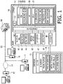
- the touchscreen panel 42 has a display panel 43 to display images, and a transparent film-like touch sensor 44 overlaid on the display panel 43, as shown in Fig. 1 .
- the touch sensor 44 is configured to output position information indicating a position where the user touches on the display panel 43.
- the display panel 43, the touch sensor 44, and the operation switches 45 of the touchscreen panel 42 are connected to a controller 51, which is described later, by cables or the like.
- the controller 51 is configured to output image data to the display panel 43, thereby displaying an image on the display panel 43.
- the controller 51 is configured to receive the position information output from the touch sensor 44.
- the controller 51 is configured to determine that the object, such as an icon, that is displayed at the position indicated by the position information input from the touch sensor 44 is the object selected by the user.
- the controller 51 is configured to receive an operation signal output by the operation switches 45.
- the touch sensor 44 and the operation switches 45 are examples of a user interface and an information interface.
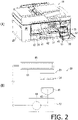
- the sheet feed tray 23 is arranged at a lower part of the housing 20, as shown in Fig. 2(A) , and is removably held by the housing 20.
- the sheet discharge tray 24 is arranged at a lower part of the housing 20 and above the sheet feed tray 23, and is held by the sheet feed tray 23 or the housing 20.
- the cover 22 is arranged at a front part of the housing 20 and is rotatably held by the housing 20.
- the cover 22 is configured to rotate between a closed position (not shown), at which the cover 22 closes an opening 30 formed on a front surface of the housing 20, and an open position ( Fig. 2(A) ), at which the cover 22 uncovers the opening 30.
- a mounting case 32 is arranged at a portion behind the opening 30 and is held in the housing 20.
- the mounting case 32 has a configuration for removably holding the cartridge 15. Since such a configuration is well known, a detailed description thereof will be omitted.
- the mounting case 32 is an example of a mounting part.
- the mounting case 32 is configured to removably hold a plurality of cartridges 15. In the example shown in the drawings, the mounting case 32 removably holds four cartridges 15. Each of the cartridges 15stores, for example, ink of one of the colors magenta, cyan, yellow, and black.
- the printer 10 is a so-called inkjet printer and a color printer. It is noted, however, the mounting case 32 may be configured to removably hold only one cartridge 15 storing black ink. That is, the printer 10 may be a so-called monochrome printer.
- the mounting case 32 may be configured to removably hold one or more cartridges 15 storing toner instead of ink. That is, the printer 10 may be a so-called laser printer.
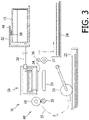
- the mounting case 32 has a cartridge I/F 49 shown in Fig. 3 .
- I/F is an abbreviation for the term "interface.”
- the cartridge I/F 49 is, for example, a terminal.
- the cartridge I/F 49 is arranged at aposition where the cartridge I/F 49 is in contact with an electrode (not shown) of an IC chip 16 of the cartridge 15 mounted in the mounting case 32.
- the cartridge I/F 49 is connected to the controller 51 (which will be described later) by a not shown cable.
- the cartridge I/F 49 may be an antenna, or a light emitting diode and a photodiode.
- the cartridge I/F 49 and the IC chip 16 may be configured to exchange information and data by radio waves or light.
- the cartridge 15 is box-shaped with an internal space for storing ink. Since a basic structure of the cartridge 15 is well known, a detailed explanation thereof is omitted.
- the ink is an example of a consumable material.
- the cartridge 15 includes the IC chip 16.
- the IC chip 16 has an electrode (not shown) in contact with the cartridge I/F 49 which is a terminal, and an IC memory 17 ( Fig. 1 ) electrically connected to the electrode.
- the IC chip 16 may have, instead of the electrode, an antenna or a light emitting diode and a photodiode.
- the IC memory 17 is configured to store various types of information.
- the IC memory 17 stores at least a model number, type information, an initial storage amount value, and a CTG serial number, as shown in Fig. 1 .
- the "CTG” is an abbreviation for a term “Cartridge.”
- the IC memory 17 is an example of a cartridge memory.
- the CTG serial number is an example of cartridge identification information.
- the model number is the identification information assigned to the cartridge 15 according to the color of the ink stored in the cartridge 15 and/or the type of the ink, such as dye or pigment.
- the type information indicates whether the cartridge 15 is for use in a contracted usage mode or in a normal usage mode.
- the type information is a onebit data that indicates "0" or "1" stored in a particular address in the IC memory 17.
- the type information "1" indicates that the cartridge is for use in the contracted usage mode
- the type information "0" indicates that the cartridge is for use in the normal usage mode.
- the type information may be a part of the model number. That is, a model number may indicate the color and type of the ink and whether cartridge is for use in the normal usage mode or contracted usage mode.
- the initial storage amount value indicates the initial amount of the ink stored in the cartridge 15.
- the initial storage amount value is used when the controller 51 calculates the ink remaining amount in the cartridge 15.
- the CTG serial number is a number that individually identifies the cartridge 15.
- the housing 20 holds a recording engine 40 therein.
- the recording engine 40 includes a sheet feed roller 25, a conveying roller 26, a sheet discharging roller 27, a platen 28, a recording unit 29, and a maintenance device 60 ( Fig. 2(B) ).
- the recording unit 29 is an example of a recording section.
- the sheet feed roller 25 is held by a frame (not shown) provided in the housing 20 so as to contact a sheet on the sheet feed tray 23.
- the sheet feed roller 25 is rotated by a motor (not shown).
- the rotating sheet feed roller 25 feeds a sheet into a conveyance path 37.
- the conveyance path 37 is a space defined by a guide member (not shown). In the example shown in the drawing, the conveyance path 37 extends in a curved manner from the rear end of the sheet feed tray 23 to a position above the sheet feed tray 23, and then extends forward.
- the conveying roller 26 is arranged downstream of the sheet feed tray 23 in a sheet conveying direction.
- the conveying roller 26 is rotated by a motor (not shown).
- the rotating conveying roller 26 and the driven roller 35 hold and convey the sheet fed into the conveyance path 37 by the sheet feed roller 25.
- the sheet discharging roller 27 is arranged downstream of the conveying roller 26 in the sheet conveying direction.
- the sheet discharging roller 27, together with a driven roller 36 constitutes a roller pair.
- the sheet discharging roller 27 is rotated by a motor (not shown).
- the rotating sheet discharging roller 27 and the driven roller 36 hold and convey the sheet and discharging the same into the sheet discharge tray 24.
- the platen 28 is arranged downstream of the conveying roller 26 and upstream of the sheet discharging roller 27 in the sheet conveying direction.
- the recording unit 29 is arranged above the platen 28.
- the recording unit 29 may be movably held by guide rails that are part of the frame, or may be fixed to the frame.
- the printer may be a so-called serial printer or a so-called line printer.
- the recording unit 29 has a head 34.
- the head 34 has a flow channel inside which ink flows. The flow channel communicates with an internal space of the cartridge 15 mounted in the mounting case 32 by a tube 31. In other words, the ink stored in the cartridge 15 is supplied to the head 34 through the tube 31.
- the head 34 has a driving element 50, which is shown in Fig. 1 .
- a portion of the driving element 50 constitutes a flow channel inside the head 34.
- the driving element 50 is electrically connected to the controller 51 by an unshown cable or the like.
- the driving element 50 is a piezoelectric element or a heater.
- the driving element 50 deforms as a DC voltage is supplied, and applies pressure to the ink in the flow channel, thereby an ink droplet being ejected from a nozzle, which are openings of the channel.
- the driving element 50 is the heater, the driving element 50 generates heat as the DC voltage is supplied, and causes the ink in the flow channel to boil, thereby an ink droplet being ejected from a nozzle.
- a maintenance device 60 shown in Fig. 2(B) has the function of suctioning the ink from the nozzles of the head 34.
- the maintenance device 60 cleans the head 34 by, for example, suctioning ink that has become highly viscous, ink mixed with air, and dust adhering to the head 34.
- the maintenance device 60 includes a cap 61, a lift-up mechanism 62, a tube 63, a pump 64, a drainage tank 65, and a pad 66.
- the cap 61 is movably held at the lift-up mechanism 62 such that the cap 61is movable between a cap position, at which the cap 61 contacts a lower surface of the head 34 and covers the nozzles, and a standby position, at which the cap 61 is separated from the lower surface of the head 34.
- the cap 61 is moved between the cap position and the standby position by an unshown motor.
- the ink suctioned by the pump 64 is discharged through the tube 63 into the drainage tank 65.
- a pad 66 that absorbs the ink is accommodated in the drainage tank 65.
- the maintenance device 60 collectively suctioning black ink, cyan ink, magenta ink, and yellow ink together is shown.
- the maintenance device 60 may be configured to separately suction black ink and colored ink such as cyan ink, magenta ink, and yellow ink.
- the printer 10 includes a controller 51.
- the controller 51 includes a CPU 52, a memory 53, and a communication bus 54.
- the CPU 52, the memory 53, the touchscreen panel 42, the operation switches 45, a communication I/F 47, the driving element 50, and the cartridge I/F 49 are connected to the communication bus 54.
- the CPU 52 is connected to the memory 53, the touchscreen panel 42, the operation switches 45, the communication I/F 47, the driving element 50, and the cartridge I/F 49 through the communication bus 54 so that information and data can be exchanged.
- the communication I/F 47 is an example of an information interface.
- the memory 53 has a ROM 55, a RAM 56, and an EEPROM 57.
- the ROM 55 stores, in advance, an OS (operating system) 58, and a control program 59. Instructions described in the OS 58 and the control program 59 are executed by the CPU 52. In other words, the OS 58 and the control program 59 are executed by the CPU 52.
- the OS 58 and the control program 59 executed by the CPU 52 display images on the display panel 43 and receive user inputs through the touch sensor 44 and/or the operation switches 45. Further, the OS 58 and the control program 59 executed by the CPU 52 transmit and receive information and/or data through the communication I/F 47 and the cartridge I/F 49. Furthermore, the OS 58 and the control program 59 executed by the CPU 52 output drive signals to the driving element 50 to record images on the sheet.
- the control program 59 may be a single program or a program including multiple modules.
- the control program 59 has a UI (User Interface) module, a communication module, and a recording control module.
- the multiple modules are executed in a pseudo-parallel manner by so-called multitasking.
- the UI module is a program that supplies image data to the display panel 43 to display images containing objects such as icons on the display panel 43, and receives signals output from the touch sensor 44 and/or the operation switches 45.
- the communication module is a program that transmits and receives information and data according to a communication protocol of a communication line to which the communication I/F 47 is connected.
- the recording control module is a program that generates and outputs drive signals to be input to the drive circuits of the above-mentioned motors and driving element 50 based on the print data.
- the RAM 56 is used for executing the OS 58 and the control program 59, and also configured to temporarily store information and/or data in executing the OS 58 and the control program 59.
- the EEPROM 57 is configured to store printer information including a main body serial number and a model name, a correspondence table, a plurality of status information types, and check table format data. Further, when the printer 10 is used in the contracted usage mode, the EEPROM 57 stores a URL published by the server 12.
- the correspondence table is an example of correspondence information.
- the main body serial number is an example of main body identification information.
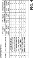
- the correspondence table has items of "number,” “status information type,” "type 1 request (user,)” “type 2 request (administrator),” and “type 3 request (service provider)” as shown in Fig. 4 . Further, each of the items of “type 1 request (user),” “type 2 request (administrator),” and “type 3 request (service provider)” has sub-items of "first mode” and second mode.”
- the “first mode” indicates that the printer 10 is used in the contracted usage mode.
- the “second mode” indicates that the printer 10 is used in the normal usage mode.
- the "type 1 request (user),” “type 2 request (administrator)” and “type 3 request (service provider)” are examples of the request type information.
- the "first mode” and “second mode” are examples of output determination information. That is, in the correspondence table, multiple status information types are associated with request type information and output determination information.
- the status information type is stored in the memory 53 in the field of the item "status information type.”
- storing of information in memory 53 in correspondence with the field of the correspondence table will be expressed as “registration in the field” or “registration in the correspondence table.”
- multiple status information types such as "printer information,” "CTG lifetime information,” “pad lifetime information,” “CTG coverage information,” “page count information,” “CTG serial number,” “main body serial number,” and “number of CTG replacement" are registered in the fields corresponding to the item "status information type.”
- the "printer information,” "CTG lifetime information” and the like registered in the fields of the correspondence table indicate the status information of the "printer information,” “CTG lifetime information” and the like stored in the EEPROM 57 of the memory 53. A detailed description thereof will be made below.
- the "printer information” is, for example, an MIB (Management Information Base) stored in the memory 53, and indicates information including the model name and the main body serial number.
- the "printer information” is the information stored in the memory 53 in advance.
- the "printer information” may include information, which is stored in the EEPROM 57 of the memory 53 after the printer 10 has been installed, such as a private IP address that the gateway device in the local network 13 has assigned to the printer 10.
- the "CTG lifetime information” indicates the information indicating the lifetime of the cartridge 15, which is determined by the controller 51 and stored in the EEPROM 57 of the memory 53.
- the controller 51 for example, counts the number of times the driving element 50 is driven as a dot count value.
- the controller 51 calculates the remaining amount of the ink stored in the cartridge 15 mounter in the mounting case 32 by subtracting the dot count value from the initial storage value read from the IC memory 17 through the cartridge I/F 49.
- the memory 53 stores in advance, for example, a table in which the remaining ink value and the lifetime are associated with each other.
- the controller 51 identifies the lifetime corresponding to the calculated ink remaining value in the table and stores the identified lifetime in the memory 53 as the CTG lifetime.
- the calculation of the remaining amount of ink stored in the 15 cartridges and the determination of the CTG lifetime is one example, and the remaining amount of the ink and/or the CTG lifetime may be determined in other methods.
- the CTG lifetime information is an example of cartridge lifetime information.
- the "pad lifetime information” indicates the information indicating the lifetime of the pad 66 ( Fig. 2(B) ).
- the “pad lifetime information” is determined by the controller 51 and stored in the EEPROM 57 of the memory 53.
- the controller 51 calculates, for example, the amount of ink that the pump 64 has suctioned from the nozzles of the head 34 (hereinafter also referred to as the amount of drainage) based on the number of times the pump 64 of the maintenance device 60 has been driven or a period of time during which the pump 64 has been driven.
- the memory 53 stores in advance, for example, a table in which the amount of drainage and the lifetime are associated with each other.
- the controller 51 identifies the lifetime corresponding to the calculated amount of drainage and stores the identified lifetime in the EEPROM 57 of the memory 53 as pad lifetime information.
- the determination of the pad lifetime is one example, and the pad lifetime may be determined in other methods.
- the "CTG coverage information” is information indicating an occupancy rate of the ink stored in each cartridge 15 mounted in the mounting case 32.
- the “CTG coverage information” is calculated by the controller 51 and stored in the EEPROM 57 of the memory 53.
- the "CTG coverage information” is information indicating percentage when the black ink ejected on the entire surface of one particular sheet of paper (A4 or Letter size) is 100%. Therefore, when black ink is ej ected in the area of half of a sheet of the above particular sheet, the black ink coverage information is 50%.
- the controller 51 calculates the coverage information for each sheet on which the recording engine 40 has recorded, and based on the calculated coverage information, calculates average CTG coverage information for a plurality of sheets on which the recording engine 40 has recorded.
- the coverage information of black ink is 50%
- the coverage information of black ink is 25%
- the "page count information” is information indicating the number of sheets recorded by the recording engine 40.
- the “page count information” is counted by the controller 51 and stored in the EEPROM 57 of the memory 53.
- the controller 51 counts the number of sheets on which the recording engine 40 has recorded images in the same manner as described above, and stores the counted number of sheets as the page count information in the EEPROM 57 of the memory 53.
- the "CTG serial number” indicates the CTG serial number of the cartridge 15 mounted in the mounting case 32.
- the controller 51 reads the CTG serial number from the IC memory 17 through the cartridge I/F 49 and stores the read CTG serial number in the memory 53.
- the "main body serial number” indicates the main body serial number of the printer 10 stored in the memory 53 in advance.
- the "number of CTG replacement” indicates the number of times the cartridge 15 has been replaced in the printer 10, which is counted by the controller 51 and stored in the EEPROM 57 of the memory 53.
- the "number of CTG replacement” is an example of replacement count information.
- the controller 51 reads, for example, the CTG serial number from the IC memory 17 through the cartridge I/F 49 and determines whether or not the read CTG serial number matches the CTG serial number stored in the EEPROM 57 of the memory 53. When the read CTG serial number does not match the CTG serial number stored in the memory 53, the controller 51 determines that the cartridge 15 has been replaced and increments the number of CTG replacement stored in the EEPROM 57 of the memory 53.
- the status information of types other than the status information of the above-described types may be registered in the correspondence table.
- the status information of the types such as "sheet jam,” which indicates that a sheet jam has occurred in the recording engine 40, "near empty,” which indicates that the amount of ink stored in the cartridge 15 is low, and "ink empty,” which indicates that there is not enough ink stored in the cartridge 15 to record an image on the sheet may be stored in the correspondence table.
- all of the status information types described above may not necessarily be registered in the correspondence table.
- the status information types of the "CTG lifetime information,” the “CTG coverage information,” the “CTG serial number,” and the “number of CTG replacement” are examples of "information on the cartridge.”
- the status information types of the "page count Information” is an example of "information corresponding to operation of the head.”
- the status information type of the "pad lifetime information” is an example of state information.
- the correspondence table has a plurality of records each of which contains one of the status information types described above.
- Each record is identified by a number such as "1” or “2" registered in the field corresponding to the item “Number.”
- "1” or “0” is registered in fields corresponding to two sub-items of the item "type 1 request (user),” fields corresponding to two sub-items of the item “type 2 request (administrator),” and fields corresponding to two sub-items of the item “type 3 request (service provider),” respectively.
- the value “1” represents that the status information indicated by the corresponding status information type is to be output.
- the value "0” represents that the status information indicated by the corresponding status information type is not to be output.
- the check table format data is data used to generate check table image data indicating a check table shown in Fig. 5 .
- the check table image data is data that is transmitted to the management device 11 or the server 12 through the local network 13 or the Internet 14, and is HTML (Hyper Text Markup Language) data or the like.
- the check table format data includes letters “export” and multiple items such as items of "printer information,” “printer condition,” and "CTG lifetime information” to be displayed below the letters "export.”
- the check table format data includes sub-items such as "model name” and "main body serial number” that are to be displayed below the item "printer information.”
- the check table format data also includes letters of "notification options 1" and "notification options 2" which are displayed on the right side with respect to the letters "export.”
- the letters “notification options 1" indicates the administrator of the printer 10.
- the letters “notification options 2" indicates the service provider.
- the check table format data has a plurality of check boxes that are displayed at positions below the "notification options 1" and on the right of the item “printer information” and other items, and the sub-item “model name” and other sub-items. Further, the check table format data has a plurality of check boxes that are displayed below the "notification options 2" and on the right of the item “printer information” and other items, and the sub-item "model name” and other sub-items. The check boxes are used to receive instructions from the administrator or the service provider as to whether or not to output the items and sub-items to be displayed on the left side.
- the check box displayed on the right side of the sub-item "model name” and below the “notification options 1" is checked.
- the checked check box represents that the status information of "model name” is to be transmitted to the management device 11.
- the check table format data is data used to receive selection of the status information type to be transmitted to the management device 11 and/or server 12.
- the check table format data further has fields, which is to be displayed between the above-described items and the check boxes, and between the above-described sub-items and the check boxes, where information can be entered.
- the field is given the same field name as the name of the item or the sub-item displayed on the left side.
- the controller 51 reads the status information stored in the EEPROM 57 of the memory 53, which is given the same name as the field name, from the memory 53 and inputs the same into the field to generate the check table image data described above from the check table format data.
- the check table image data also includes a script for receiving checks of the check boxes.
- the controller 51 determines mode to be the first mode when the printer 10 is used in the contracted usage mode, and determines the mode to be the second mode when the printer 10 is used in the normal usage mode.
- the controller 51 reads the type information from the IC memory 17 through the cartridge I/F 49 in response to the cartridge 15 being attached to the mounting case 32 or in response to the printer 10 being turned on.
- the controller 51 determines that the read type information is "1," the controller 51 determines the mode is to be the first mode, while when the type information read is "0,” the controller 51 determines the mode to be the second mode.
- the controller 51 determines the mode by storing mode information indicating the determined mode in a particular area in the EEPROM 57 of the memory 53 that is defined as an area where the mode information indicating the mode is to be stored.
- the type information read from the IC memory 17 of the cartridge 15 is an example of usage type information.
- the mode information is an example of output determination information. It is noted that the above-described process in which the controller 51 determines the mode is only one example of determining the mode, and the controller 51 may determine the mode in accordance with other methods.
- the controller 51 In response to the determined mode being the first mode, the controller 51 periodically transmits an HTTP request (hereinafter simply referred to as a "request") in accordance with the HTTP communication protocol to a URL stored in the EEPROM 57 of the memory 53, through the communication I/F 47, the local network 13, and the Internet 14 (hereinafter simply referred to as "through the communication I/F 47") (S11). In other words, the controller 51 executes so-called polling in order to receive instructions from the server 12.
- a request hereinafter simply referred to as a "request”
- the program implemented in the server 12 receives instructions from the service provider and transmits an HTTP response (hereinafter simply referred to as a "response") containing a command requesting a check table to the printer 10 through the Internet 14 and the local network 13 (S12).
- the controller 51 receives the response transmitted by the server 12 through the communication I/F 47 (S12).
- the controller 51 generates the above-described check table image data according to the commands contained in the received response (S13).
- the controller 51 transmits a request containing the generated check table image data to the server 12 through the communication I/F 47 (S14).
- the program implemented in the server 12 receives the request transmitted by the printer 10 (S14), displays on the display of the server 12 the check table ( Fig.
- the program of the server 12 changes presence or absence of the check in the check table according to the received instructions from the service provider, and waits until receiving a request transmitted from the printer 10. Then, in response to receiving the request transmitted from the printer 10 (S16), the program of the server 12 generates a response including the check table in which the presence or absence of each check has been modified (hereinafter referred to as a "modified check table"). The program of the server 12 transmits the generated response to the printer 10 through the Internet 14 and the local network 13 (S17).
- the controller 51 When the controller 51 receives the response transmitted to the server 12 (S17), the controller 51 obtains the modified check table contained in the received response. The controller 51 stores check information indicating each check box in the obtained modified check table is checked or not in the EEPROM 57 of the memory 53 (S18). In response to the determined mode being the second mode, the controller 51 does not perform the processes from S11 to S18.
- the controller 51 receives a request including a command to request the check table from the management device 11 through the local network 13 and the communication I/F 47 (S21). In response to receipt of the command, the controller 51 generates check table image data (S22) and transmits the generated check table image data to the management device 11 through the communication I/F 47 and the local network 13 (S23).
- the program implemented in the management device 11 receives the check table image data
- the program displays the check table indicated by the check table image data on the display of the management device 11, and receives input from the administrator (S24).
- the program implemented in the management device 11 changes the presence or absence of checks in the check table according to the instructions received from the administrator, and generates a modified check table.
- the program implemented in the management device 11 transmits the generated modified check table to the printer 10 through the local network 13 (S25).
- the controller 51 receives the modified check table transmitted by the management device 11 through the communication I/F 47 (S25), and stores the check information indicating each check box in the received modified check table is checked or not in the EEPROM 57 of the memory 53 (S26). It is noted that the above-described process of the controller 51 to receive the instructions of the service provider or the administrator indicating the status information type to be transmitted by the printer 10 is one example, and the controller 51 may receive the instructions of the service provider or the administrator according to other methods.
- the controller 51 determines whether an output request for outputting the status information has been received.
- the output request is transmitted from the server 12, the management device 11, or the touch sensor 44 of the touchscreen panel 42.
- the program implemented in the server 12 transmits a response including the output request through the Internet 14 and the local network 13 in the same manner as in S12.
- the controller 51 receives the response including the output request through the communication I/F 47 (S31: YES).
- the program implemented in the management device 11 transmits the output request to the printer 10 through the local network 13.
- the controller 51 receives the output request transmitted by the printer 10 through the local network 13 and the communication I/F 47 (S31: YES).
- the user touches the touch sensor 44 of the touchscreen panel 42 to input the output request to the printer 10.
- the controller 51 receives the output request input from the touch sensor 44 (S31: YES).
- the controller 51 terminates the status information output process. It is noted that the controller 51 executes the status information output process periodically.
- the controller 51 determines a source of the output request is the server 12, the management device 11, or the touch sensor 44 (S32). For example, the controller 51 determines that the output request was acquired from the server 12 based on that an IP address of the server 12 is included in the HTTP response containing the output request (S32: SERVER). Alternatively, based on that an IP address of the management device 11 is included in the received output request, the controller 51 determines that the output request was obtained from the management device 11 (S32: MANAGEMENT DEVICE).
- the controller 51 determines the output request type to be the type 1 request (S33).
- the controller 51 determines the output request type to be the type 2 request (S34).
- the controller 51 determines the output request type to be the type 3 request (S35).
- the controller 51 reads the mode information stored in the EEPROM 57 of the memory 53 (S36).
- the controller 51 executes an output status information identification process (S37) to identify the status information type to be output based on the determined output request type and the read mode information. It is noted that information indicating whether the output request is input from the touch sensor, from the management device 11, or from the server 12 is an example of request type information.
- the output status information identification process is described with reference to Fig. 8 .
- the controller 51 reads, from the memory 53, the check information which was stored in the memory 53 in S18 or S26 (S51).
- the controller 51 identifies the status information type to be output based on the read check information and the output request type determined in S33 to S35 (S52). For example, when the determined output request type is the type 1 request (Notification Options 1) and the check box corresponding to the sub-item "Total" of the item "Sheet count per paper type" is checked as shown in the check table ( Fig. 5 ), the controller 51 identifies "total number of sheets printed by paper type" as the status information type to be output.
- the controller 51 reads the status information indicated by the identified status information type from the EEPROM 57 of the memory 53, and stores the read status information in the RAM 56 as the status information to be output (S53).
- the controller 51 sets the value "i" stored in the particular storage area of the EEPROM 57 of the memory 53 to the initial value "1" (S54).
- the controller 51 identifies the record in which the item "number” is “1” which is the value "i.”
- the controller 51 obtains a corresponding value ("0" or “1") corresponding to the output request type determined in S33 to S35 and the mode information read from the EEPROM 57 of the memory 53 in S36 (S55).
- the controller 51 obtains the corresponding value "1.” In addition, the controller 51 obtains the status information type "printer information" registered in the identified record. The controller 51 determines whether the obtained corresponding value is "1" or "0" (S56). When the controller 51 determines that the obtained corresponding value is "1" (S56: “1"), the controller 51 determines whether the check information contains information indicating that the check box corresponding to the status information type "printer information" is checked (S57).
- the controller 51 determines that the check box corresponding to the status information type "printer information" is checked (S57: YES)
- the controller 51 executes the process S58. Concretely, the controller 51 reads, as the status information to be output, the printer information stored in the memory 53 as the status information type "printer information" from the memory 53, and stores the read status information in the RAM 56 (S58).
- the controller 51 determines that the obtained corresponding value is "0" in S56 (S56: “0")
- the controller 51 skips the processes S57 and S58.
- the controller 51 determines that the check box corresponding to the status information type "printer information" is not checked (S57: NO)
- the controller 51 skips the process S58.
- the controller 51 increments the value "i" (S59) and determines whether the incremented value "i" is greater than or equal to a maximum value stored in the memory 53 (S60).
- the maximum value is stored in the memory 53 as the number of records registered in the correspondence table. That is, in S60, it is determined whether or not all the records registered in the correspondence table have been determined to be status information which is to be output.
- the controller 51 determines that the value "i" is less than the maximum value (S60: NO)
- the controller 51 executes the process from S54 onward again.
- the controller 51 determines that the value "i" is greater than or equal to the maximum value (S60: YES)
- the controller 51 terminates the output status information identification process and executes the process S38 of the status information output process shown in Fig. 7 .
- the controller 51 generates output data including the status information stored in the RAM 56 in S58 (S38). Then, the controller 51 determines an output destination of the generated output data based on the output request type (S39), and transmits the generated output data to the determined output destination. Concretely, when the controller 51 determines that the output request type is the type 1 request (S39: "type 1 request"), the controller 51 outputs the generated output data to the display panel 43 of the touchscreen panel 42 (S40). That is, the controller 51 causes the display panel 43 to display the status information stored in the RAM 56 in S53 as the status information to be output.
- the controller 51 determines that the output request type is the type 2 request (S39: “type 2 request”)
- the controller 51 transmits the generated output data to the management device 11 through the local network 13 (S41).
- the program implemented in the management device 11 receives the output data and displays the status information contained in the received output data on the display of the management device 11.
- the controller 51 determines that the output request type is the type 3 request (S39: “type 3 request")
- the controller 51 generates a request containing the generated output data.
- the controller 51 transmits the generated request to the server 12 through the communication I/F 47 (S42).
- the program implemented in the server 12 receives the request containing the output data and displays the status information contained in the received output data on the display of the server 12.
- the controller 51 terminates the status information output process in response to transmission of the output data to the touchscreen panel 42, the management device 11, or the server 12.
- the controller 51 identifies the status information type based on the determined output request type, the mode indicated by the mode information, and the correspondence table stored in the memory 53 among the plurality of status information stored in the EEPROM 57. Then, the controller 51 reads the status information indicated by the identified status information type from the memory 53 and outputs the read status information.
- the printer 10 can change the status information type to be output according to whether the type of the cartridge 15 mounted in the mounting case 32 is in the contracted usage mode or the normal usage mode, and according to whether the user requesting the status information is a user, an administrator or a service provider.
- the status information such as the CTG lifetime information, the pad lifetime information, and the CTG coverage information are not necessary for the user, and if such information is displayed on the touchscreen panel 42 together with the necessary information for the user, it will be difficult for the user to recognize the necessary information.
- the printer identifies the status information necessary for a user who made the output request in the correspondence table, and outputs the identified status information. Therefore, the printer 10 helps the user who made the output request recognize the status information required by the user who made the output request.
- the controller 51 transmits the check table image data to the management device 11 or the server 12, receives the check information indicating the instructions of the administrator or the service provider, and obtains the status information type to be output based on the received check information (S55).
- the printer 10 can also allow the administrator or service provider to select the status information type to be output.
- the controller 51 determines that the output request type is the type 2 request based on that the controller 51 has received the output request transmitted from the management device 11.
- the controller 51 may determine that the output request type is the type 2 request based on that the output request received through the communication I/F 47 includes administrator information such as an account indicating the administrator. In that case, the controller 51 determines that the output request type is the type 1 request based on that the administrator information is not included in the output request received through the communication I/F 47.
- the controller 51 receives, for example, an output request transmitted from a management device 11 other than the management device 11 used by the administrator, the controller 51 determines whether the received output request contains the administrator information.
- the administrator information is an example of the request type information.
- the controller 51 determines that the output request type is the type 1 request based on that the output request is received through the touch sensor 44.
- the controller 51 may determine that the output request type is the type 2 request based on that the above-described administrator information is included in the output request received through the touch sensor 44. In that case, the controller 51 determines that the output request type is the type 1 request based on that the above-described administrator information is not included in the output request received through the touch sensor 44.
- the administrator information is an example of the request type information.
- the controller 51 determines that the output request type is the type 3 request based on that the controller 51 has received a response that includes the output request.
- the controller 51 may determine that the output request type is the type 3 request based on that the received output request includes service provider information such as an account indicating the service provider.
- the controller 51 outputs the output data to the display panel 43 of the touchscreen panel 42 when it is determined that the output request type is the type 1 request.
- the controller 51 may drive the recording engine 40 to record the status information included in the output data on the sheet.
- the controller 51 may drive the recording engine 40 to record the status information on the sheet in response to the obtained output request including an instruction to record the status information on the sheet.
- controller 51 transmits a request including the output data to the server 12 in S42.
- the controller 51 may, instead of or together with the process in S42, send an e-mail containing the output data to an e-mail address that the service provider has.
Landscapes
- Engineering & Computer Science (AREA)
- Theoretical Computer Science (AREA)
- Physics & Mathematics (AREA)
- General Physics & Mathematics (AREA)
- General Engineering & Computer Science (AREA)
- Human Computer Interaction (AREA)
- Signal Processing (AREA)
- Multimedia (AREA)
- Health & Medical Sciences (AREA)
- Biomedical Technology (AREA)
- General Health & Medical Sciences (AREA)
- Mathematical Physics (AREA)
- Microelectronics & Electronic Packaging (AREA)
- Computing Systems (AREA)
- Accessory Devices And Overall Control Thereof (AREA)
- Ink Jet (AREA)
- Control Or Security For Electrophotography (AREA)
- Facsimiles In General (AREA)
Applications Claiming Priority (2)
| Application Number | Priority Date | Filing Date | Title |
|---|---|---|---|
| JP2019120836A JP7404674B2 (ja) | 2019-06-28 | 2019-06-28 | 画像記録装置 |
| PCT/JP2020/023175 WO2020262037A1 (ja) | 2019-06-28 | 2020-06-12 | 画像記録装置 |
Publications (3)
| Publication Number | Publication Date |
|---|---|
| EP3991973A1 true EP3991973A1 (de) | 2022-05-04 |
| EP3991973A4 EP3991973A4 (de) | 2023-06-21 |
| EP3991973B1 EP3991973B1 (de) | 2024-08-21 |
Family
ID=74061895
Family Applications (1)
| Application Number | Title | Priority Date | Filing Date |
|---|---|---|---|
| EP20832053.1A Active EP3991973B1 (de) | 2019-06-28 | 2020-06-12 | Bildaufzeichnungsvorrichtung |
Country Status (5)
| Country | Link |
|---|---|
| US (1) | US11989467B2 (de) |
| EP (1) | EP3991973B1 (de) |
| JP (1) | JP7404674B2 (de) |
| CN (1) | CN114072287B (de) |
| WO (1) | WO2020262037A1 (de) |
Families Citing this family (1)
| Publication number | Priority date | Publication date | Assignee | Title |
|---|---|---|---|---|
| WO2022071930A1 (en) * | 2020-09-30 | 2022-04-07 | Hewlett-Packard Development Company, L.P. | Printing device entry into reduced print material usage mode |
Family Cites Families (30)
| Publication number | Priority date | Publication date | Assignee | Title |
|---|---|---|---|---|
| US5355159A (en) * | 1990-10-08 | 1994-10-11 | Canon Kabushiki Kaisha | Color facsimile apparatus which warns of colorant aromalies |
| JP3872278B2 (ja) * | 2000-01-19 | 2007-01-24 | セイコーエプソン株式会社 | カートリッジを利用してユーザに利益を供与する画像形成システム |
| JP3501762B2 (ja) | 2000-02-14 | 2004-03-02 | キヤノン株式会社 | 情報処理装置及び方法 |
| JP3885047B2 (ja) * | 2000-02-14 | 2007-02-21 | キヤノン株式会社 | 情報処理装置及び情報処理方法 |
| JP2002211087A (ja) | 2001-01-23 | 2002-07-31 | Seiko Epson Corp | プリンタ、印刷制御装置およびカートリッジ個数算出方法 |
| US6820972B2 (en) * | 2002-03-29 | 2004-11-23 | Hewlett-Packard Development Company, L.P. | Printing cartridge pigment replenishment apparatus and method |
| JP2004046615A (ja) * | 2002-07-12 | 2004-02-12 | Ricoh Co Ltd | 周辺機器管理システム |
| US7212637B2 (en) * | 2003-03-11 | 2007-05-01 | Rimage Corporation | Cartridge validation with radio frequency identification |
| JP2005301126A (ja) | 2004-04-15 | 2005-10-27 | Seiko Epson Corp | ステータス情報管理装置、ステータス情報管理方法およびステータス情報管理プログラム |
| DE602006010793D1 (de) | 2005-10-31 | 2010-01-14 | Seiko Epson Corp | Drucker und Drucksystem |
| JP4742815B2 (ja) * | 2005-10-31 | 2011-08-10 | セイコーエプソン株式会社 | プリンタ、プリンタシステム及び課金方法 |
| JP2008227914A (ja) * | 2007-03-13 | 2008-09-25 | Murata Mach Ltd | 画像形成装置 |
| JP2009298051A (ja) | 2008-06-13 | 2009-12-24 | Fuji Xerox Co Ltd | 画像形成装置、画像形成装置の障害診断システムおよび画像形成装置の障害診断プログラム |
| US20100141705A1 (en) * | 2008-12-08 | 2010-06-10 | Eastman Kodak Company | Compact waste ink absorber facilitating fluid evaporation |
| TWI501209B (zh) * | 2009-07-24 | 2015-09-21 | Cheng Ta Yang | 網路互動式教學管理系統 |
| JP5257468B2 (ja) * | 2011-01-31 | 2013-08-07 | ブラザー工業株式会社 | 液滴噴射装置 |
| JP5560223B2 (ja) * | 2011-03-18 | 2014-07-23 | セイコーエプソン株式会社 | インクカートリッジの管理システム及びインクカートリッジの管理システムの制御方法 |
| JP2013182437A (ja) * | 2012-03-02 | 2013-09-12 | Canon Inc | デバイス監視方法及びそのシステム、管理装置 |
| HK1204104A1 (en) | 2012-04-26 | 2015-11-06 | 纽碧印刷有限公司 | Remote program control device for copiers and printers |
| JP2015208990A (ja) * | 2014-04-30 | 2015-11-24 | セイコーエプソン株式会社 | 液体噴射装置 |
| JP6503986B2 (ja) * | 2015-09-01 | 2019-04-24 | 富士ゼロックス株式会社 | 画像処理システム、情報処理装置及びプログラム |
| JP6904714B2 (ja) * | 2017-01-16 | 2021-07-21 | 理想科学工業株式会社 | インクジェット印刷装置 |
| JP2019010825A (ja) * | 2017-06-30 | 2019-01-24 | キヤノン株式会社 | 画像形成装置およびマイコンデバイス |
| JP6590895B2 (ja) * | 2017-11-20 | 2019-10-16 | キヤノン株式会社 | 画像形成装置及び画像形成方法 |
| CN111819083B (zh) * | 2018-03-08 | 2022-03-29 | 惠普发展公司,有限责任合伙企业 | 附属装置、伪盒、用于将伪盒插入到打印机中的方法 |
| WO2019236787A1 (en) * | 2018-06-07 | 2019-12-12 | Videojet Technologies Inc. | Dna-tagged inks and systems and methods of use |
| US11479046B2 (en) * | 2018-12-03 | 2022-10-25 | Hewlett-Packard Development Company, L.P. | Logic circuitry for sensor data communications |
| CN110202940A (zh) * | 2019-05-06 | 2019-09-06 | 珠海艾派克微电子有限公司 | 打印耗材、墨盒及控制方法 |
| US11092920B2 (en) * | 2019-09-30 | 2021-08-17 | Brother Kogyo Kabushiki Kaisha | Image forming apparatus |
| JP7579509B2 (ja) * | 2020-03-30 | 2024-11-08 | ブラザー工業株式会社 | 画像形成装置、制御方法、およびカートリッジ |
-
2019
- 2019-06-28 JP JP2019120836A patent/JP7404674B2/ja active Active
-
2020
- 2020-06-12 EP EP20832053.1A patent/EP3991973B1/de active Active
- 2020-06-12 CN CN202080047909.6A patent/CN114072287B/zh active Active
- 2020-06-12 WO PCT/JP2020/023175 patent/WO2020262037A1/ja not_active Ceased
-
2021
- 2021-12-28 US US17/563,747 patent/US11989467B2/en active Active
Also Published As
| Publication number | Publication date |
|---|---|
| JP7404674B2 (ja) | 2023-12-26 |
| CN114072287B (zh) | 2023-08-29 |
| JP2021007201A (ja) | 2021-01-21 |
| EP3991973B1 (de) | 2024-08-21 |
| WO2020262037A1 (ja) | 2020-12-30 |
| US20220121404A1 (en) | 2022-04-21 |
| EP3991973A4 (de) | 2023-06-21 |
| US11989467B2 (en) | 2024-05-21 |
| CN114072287A (zh) | 2022-02-18 |
Similar Documents
| Publication | Publication Date | Title |
|---|---|---|
| JP7156135B2 (ja) | 画像記録装置 | |
| US9607254B2 (en) | Image recording apparatus, server, and communication system | |
| US11740578B2 (en) | Monitoring device, image recordation monitoring method, and printer | |
| US11413876B2 (en) | Image recording apparatus, communication system, and computer-readable medium for permitting another apparatus to temporarily use a cartridge for the image recording apparatus | |
| JP2021121482A (ja) | 記録装置、発注システム、制御方法、およびプログラム | |
| US5742310A (en) | Ink jet printer and an ink storing member mounted on the printer | |
| JP2020183118A (ja) | 画像記録装置 | |
| US11733933B2 (en) | Image recording device | |
| JP4245411B2 (ja) | 画像形成装置 | |
| JP2020163594A (ja) | 画像記録装置、及びバックアップ方法 | |
| EP3991973B1 (de) | Bildaufzeichnungsvorrichtung | |
| JP7268444B2 (ja) | 画像記録装置 | |
| JP7290059B2 (ja) | 画像記録装置 | |
| US20220317941A1 (en) | Method for switching image forming apparatus, image forming apparatus, and information processing apparatus | |
| US11999170B2 (en) | Image recording device and computer readable medium | |
| US7063399B2 (en) | Imaging apparatus and method for facilitating printing | |
| JP7293913B2 (ja) | 画像記録装置 | |
| WO2020196730A1 (ja) | 画像記録装置 | |
| JP7375346B2 (ja) | 画像記録装置 | |
| US7918527B2 (en) | Method for use in achieving velocity optimization for a printhead | |
| JP2020168828A (ja) | 記録装置、制御方法及びプログラム | |
| JP2019177498A (ja) | 液体消費システム | |
| JP2006212866A (ja) | 画像形成装置、プログラム、記録媒体 | |
| JP2004142334A (ja) | インクジェット記録装置 |
Legal Events
| Date | Code | Title | Description |
|---|---|---|---|
| STAA | Information on the status of an ep patent application or granted ep patent |
Free format text: STATUS: THE INTERNATIONAL PUBLICATION HAS BEEN MADE |
|
| PUAI | Public reference made under article 153(3) epc to a published international application that has entered the european phase |
Free format text: ORIGINAL CODE: 0009012 |
|
| STAA | Information on the status of an ep patent application or granted ep patent |
Free format text: STATUS: REQUEST FOR EXAMINATION WAS MADE |
|
| 17P | Request for examination filed |
Effective date: 20220106 |
|
| AK | Designated contracting states |
Kind code of ref document: A1 Designated state(s): AL AT BE BG CH CY CZ DE DK EE ES FI FR GB GR HR HU IE IS IT LI LT LU LV MC MK MT NL NO PL PT RO RS SE SI SK SM TR |
|
| DAV | Request for validation of the european patent (deleted) | ||
| DAX | Request for extension of the european patent (deleted) | ||
| REG | Reference to a national code |
Ref country code: DE Ref legal event code: R079 Free format text: PREVIOUS MAIN CLASS: B41J0002010000 Ipc: B41J0002175000 Ref document number: 602020036369 Country of ref document: DE |
|
| A4 | Supplementary search report drawn up and despatched |
Effective date: 20230524 |
|
| RIC1 | Information provided on ipc code assigned before grant |
Ipc: G06F 3/12 20060101ALI20230517BHEP Ipc: G03G 15/00 20060101ALI20230517BHEP Ipc: B41J 29/13 20060101ALI20230517BHEP Ipc: H04N 1/00 20060101ALI20230517BHEP Ipc: B41J 2/175 20060101AFI20230517BHEP |
|
| P01 | Opt-out of the competence of the unified patent court (upc) registered |
Effective date: 20230529 |
|
| GRAP | Despatch of communication of intention to grant a patent |
Free format text: ORIGINAL CODE: EPIDOSNIGR1 |
|
| STAA | Information on the status of an ep patent application or granted ep patent |
Free format text: STATUS: GRANT OF PATENT IS INTENDED |
|
| INTG | Intention to grant announced |
Effective date: 20240412 |
|
| GRAS | Grant fee paid |
Free format text: ORIGINAL CODE: EPIDOSNIGR3 |
|
| GRAA | (expected) grant |
Free format text: ORIGINAL CODE: 0009210 |
|
| STAA | Information on the status of an ep patent application or granted ep patent |
Free format text: STATUS: THE PATENT HAS BEEN GRANTED |
|
| AK | Designated contracting states |
Kind code of ref document: B1 Designated state(s): AL AT BE BG CH CY CZ DE DK EE ES FI FR GB GR HR HU IE IS IT LI LT LU LV MC MK MT NL NO PL PT RO RS SE SI SK SM TR |
|
| REG | Reference to a national code |
Ref country code: GB Ref legal event code: FG4D |
|
| REG | Reference to a national code |
Ref country code: CH Ref legal event code: EP |
|
| REG | Reference to a national code |
Ref country code: IE Ref legal event code: FG4D |
|
| REG | Reference to a national code |
Ref country code: DE Ref legal event code: R096 Ref document number: 602020036369 Country of ref document: DE |
|
| REG | Reference to a national code |
Ref country code: LT Ref legal event code: MG9D |
|
| REG | Reference to a national code |
Ref country code: NL Ref legal event code: MP Effective date: 20240821 |
|
| PG25 | Lapsed in a contracting state [announced via postgrant information from national office to epo] |
Ref country code: NO Free format text: LAPSE BECAUSE OF FAILURE TO SUBMIT A TRANSLATION OF THE DESCRIPTION OR TO PAY THE FEE WITHIN THE PRESCRIBED TIME-LIMIT Effective date: 20241121 |
|
| REG | Reference to a national code |
Ref country code: AT Ref legal event code: MK05 Ref document number: 1715180 Country of ref document: AT Kind code of ref document: T Effective date: 20240821 |
|
| PG25 | Lapsed in a contracting state [announced via postgrant information from national office to epo] |
Ref country code: NL Free format text: LAPSE BECAUSE OF FAILURE TO SUBMIT A TRANSLATION OF THE DESCRIPTION OR TO PAY THE FEE WITHIN THE PRESCRIBED TIME-LIMIT Effective date: 20240821 Ref country code: PT Free format text: LAPSE BECAUSE OF FAILURE TO SUBMIT A TRANSLATION OF THE DESCRIPTION OR TO PAY THE FEE WITHIN THE PRESCRIBED TIME-LIMIT Effective date: 20241223 Ref country code: GR Free format text: LAPSE BECAUSE OF FAILURE TO SUBMIT A TRANSLATION OF THE DESCRIPTION OR TO PAY THE FEE WITHIN THE PRESCRIBED TIME-LIMIT Effective date: 20241122 Ref country code: PL Free format text: LAPSE BECAUSE OF FAILURE TO SUBMIT A TRANSLATION OF THE DESCRIPTION OR TO PAY THE FEE WITHIN THE PRESCRIBED TIME-LIMIT Effective date: 20240821 Ref country code: FI Free format text: LAPSE BECAUSE OF FAILURE TO SUBMIT A TRANSLATION OF THE DESCRIPTION OR TO PAY THE FEE WITHIN THE PRESCRIBED TIME-LIMIT Effective date: 20240821 |
|
| PG25 | Lapsed in a contracting state [announced via postgrant information from national office to epo] |
Ref country code: BG Free format text: LAPSE BECAUSE OF FAILURE TO SUBMIT A TRANSLATION OF THE DESCRIPTION OR TO PAY THE FEE WITHIN THE PRESCRIBED TIME-LIMIT Effective date: 20240821 |
|
| PG25 | Lapsed in a contracting state [announced via postgrant information from national office to epo] |
Ref country code: LV Free format text: LAPSE BECAUSE OF FAILURE TO SUBMIT A TRANSLATION OF THE DESCRIPTION OR TO PAY THE FEE WITHIN THE PRESCRIBED TIME-LIMIT Effective date: 20240821 |
|
| PG25 | Lapsed in a contracting state [announced via postgrant information from national office to epo] |
Ref country code: AT Free format text: LAPSE BECAUSE OF FAILURE TO SUBMIT A TRANSLATION OF THE DESCRIPTION OR TO PAY THE FEE WITHIN THE PRESCRIBED TIME-LIMIT Effective date: 20240821 Ref country code: IS Free format text: LAPSE BECAUSE OF FAILURE TO SUBMIT A TRANSLATION OF THE DESCRIPTION OR TO PAY THE FEE WITHIN THE PRESCRIBED TIME-LIMIT Effective date: 20241221 |
|
| PG25 | Lapsed in a contracting state [announced via postgrant information from national office to epo] |
Ref country code: HR Free format text: LAPSE BECAUSE OF FAILURE TO SUBMIT A TRANSLATION OF THE DESCRIPTION OR TO PAY THE FEE WITHIN THE PRESCRIBED TIME-LIMIT Effective date: 20240821 |
|
| PG25 | Lapsed in a contracting state [announced via postgrant information from national office to epo] |
Ref country code: ES Free format text: LAPSE BECAUSE OF FAILURE TO SUBMIT A TRANSLATION OF THE DESCRIPTION OR TO PAY THE FEE WITHIN THE PRESCRIBED TIME-LIMIT Effective date: 20240821 Ref country code: RS Free format text: LAPSE BECAUSE OF FAILURE TO SUBMIT A TRANSLATION OF THE DESCRIPTION OR TO PAY THE FEE WITHIN THE PRESCRIBED TIME-LIMIT Effective date: 20241121 |
|
| PG25 | Lapsed in a contracting state [announced via postgrant information from national office to epo] |
Ref country code: RS Free format text: LAPSE BECAUSE OF FAILURE TO SUBMIT A TRANSLATION OF THE DESCRIPTION OR TO PAY THE FEE WITHIN THE PRESCRIBED TIME-LIMIT Effective date: 20241121 Ref country code: PT Free format text: LAPSE BECAUSE OF FAILURE TO SUBMIT A TRANSLATION OF THE DESCRIPTION OR TO PAY THE FEE WITHIN THE PRESCRIBED TIME-LIMIT Effective date: 20241223 Ref country code: PL Free format text: LAPSE BECAUSE OF FAILURE TO SUBMIT A TRANSLATION OF THE DESCRIPTION OR TO PAY THE FEE WITHIN THE PRESCRIBED TIME-LIMIT Effective date: 20240821 Ref country code: NO Free format text: LAPSE BECAUSE OF FAILURE TO SUBMIT A TRANSLATION OF THE DESCRIPTION OR TO PAY THE FEE WITHIN THE PRESCRIBED TIME-LIMIT Effective date: 20241121 Ref country code: NL Free format text: LAPSE BECAUSE OF FAILURE TO SUBMIT A TRANSLATION OF THE DESCRIPTION OR TO PAY THE FEE WITHIN THE PRESCRIBED TIME-LIMIT Effective date: 20240821 Ref country code: LV Free format text: LAPSE BECAUSE OF FAILURE TO SUBMIT A TRANSLATION OF THE DESCRIPTION OR TO PAY THE FEE WITHIN THE PRESCRIBED TIME-LIMIT Effective date: 20240821 Ref country code: IS Free format text: LAPSE BECAUSE OF FAILURE TO SUBMIT A TRANSLATION OF THE DESCRIPTION OR TO PAY THE FEE WITHIN THE PRESCRIBED TIME-LIMIT Effective date: 20241221 Ref country code: HR Free format text: LAPSE BECAUSE OF FAILURE TO SUBMIT A TRANSLATION OF THE DESCRIPTION OR TO PAY THE FEE WITHIN THE PRESCRIBED TIME-LIMIT Effective date: 20240821 Ref country code: GR Free format text: LAPSE BECAUSE OF FAILURE TO SUBMIT A TRANSLATION OF THE DESCRIPTION OR TO PAY THE FEE WITHIN THE PRESCRIBED TIME-LIMIT Effective date: 20241122 Ref country code: FI Free format text: LAPSE BECAUSE OF FAILURE TO SUBMIT A TRANSLATION OF THE DESCRIPTION OR TO PAY THE FEE WITHIN THE PRESCRIBED TIME-LIMIT Effective date: 20240821 Ref country code: ES Free format text: LAPSE BECAUSE OF FAILURE TO SUBMIT A TRANSLATION OF THE DESCRIPTION OR TO PAY THE FEE WITHIN THE PRESCRIBED TIME-LIMIT Effective date: 20240821 Ref country code: BG Free format text: LAPSE BECAUSE OF FAILURE TO SUBMIT A TRANSLATION OF THE DESCRIPTION OR TO PAY THE FEE WITHIN THE PRESCRIBED TIME-LIMIT Effective date: 20240821 Ref country code: AT Free format text: LAPSE BECAUSE OF FAILURE TO SUBMIT A TRANSLATION OF THE DESCRIPTION OR TO PAY THE FEE WITHIN THE PRESCRIBED TIME-LIMIT Effective date: 20240821 |
|
| PG25 | Lapsed in a contracting state [announced via postgrant information from national office to epo] |
Ref country code: SM Free format text: LAPSE BECAUSE OF FAILURE TO SUBMIT A TRANSLATION OF THE DESCRIPTION OR TO PAY THE FEE WITHIN THE PRESCRIBED TIME-LIMIT Effective date: 20240821 Ref country code: RO Free format text: LAPSE BECAUSE OF FAILURE TO SUBMIT A TRANSLATION OF THE DESCRIPTION OR TO PAY THE FEE WITHIN THE PRESCRIBED TIME-LIMIT Effective date: 20240821 Ref country code: DK Free format text: LAPSE BECAUSE OF FAILURE TO SUBMIT A TRANSLATION OF THE DESCRIPTION OR TO PAY THE FEE WITHIN THE PRESCRIBED TIME-LIMIT Effective date: 20240821 |
|
| PG25 | Lapsed in a contracting state [announced via postgrant information from national office to epo] |
Ref country code: EE Free format text: LAPSE BECAUSE OF FAILURE TO SUBMIT A TRANSLATION OF THE DESCRIPTION OR TO PAY THE FEE WITHIN THE PRESCRIBED TIME-LIMIT Effective date: 20240821 |
|
| PG25 | Lapsed in a contracting state [announced via postgrant information from national office to epo] |
Ref country code: CZ Free format text: LAPSE BECAUSE OF FAILURE TO SUBMIT A TRANSLATION OF THE DESCRIPTION OR TO PAY THE FEE WITHIN THE PRESCRIBED TIME-LIMIT Effective date: 20240821 |
|
| PG25 | Lapsed in a contracting state [announced via postgrant information from national office to epo] |
Ref country code: SK Free format text: LAPSE BECAUSE OF FAILURE TO SUBMIT A TRANSLATION OF THE DESCRIPTION OR TO PAY THE FEE WITHIN THE PRESCRIBED TIME-LIMIT Effective date: 20240821 Ref country code: IT Free format text: LAPSE BECAUSE OF FAILURE TO SUBMIT A TRANSLATION OF THE DESCRIPTION OR TO PAY THE FEE WITHIN THE PRESCRIBED TIME-LIMIT Effective date: 20240821 |
|
| REG | Reference to a national code |
Ref country code: DE Ref legal event code: R097 Ref document number: 602020036369 Country of ref document: DE |
|
| PLBE | No opposition filed within time limit |
Free format text: ORIGINAL CODE: 0009261 |
|
| STAA | Information on the status of an ep patent application or granted ep patent |
Free format text: STATUS: NO OPPOSITION FILED WITHIN TIME LIMIT |
|
| PGFP | Annual fee paid to national office [announced via postgrant information from national office to epo] |
Ref country code: DE Payment date: 20250509 Year of fee payment: 6 |
|
| PGFP | Annual fee paid to national office [announced via postgrant information from national office to epo] |
Ref country code: GB Payment date: 20250508 Year of fee payment: 6 |
|
| PGFP | Annual fee paid to national office [announced via postgrant information from national office to epo] |
Ref country code: FR Payment date: 20250512 Year of fee payment: 6 |
|
| 26N | No opposition filed |
Effective date: 20250522 |
|
| PG25 | Lapsed in a contracting state [announced via postgrant information from national office to epo] |
Ref country code: SE Free format text: LAPSE BECAUSE OF FAILURE TO SUBMIT A TRANSLATION OF THE DESCRIPTION OR TO PAY THE FEE WITHIN THE PRESCRIBED TIME-LIMIT Effective date: 20240821 |
|
| REG | Reference to a national code |
Ref country code: CH Ref legal event code: H13 Free format text: ST27 STATUS EVENT CODE: U-0-0-H10-H13 (AS PROVIDED BY THE NATIONAL OFFICE) Effective date: 20260127 |
|
| PG25 | Lapsed in a contracting state [announced via postgrant information from national office to epo] |
Ref country code: MC Free format text: LAPSE BECAUSE OF FAILURE TO SUBMIT A TRANSLATION OF THE DESCRIPTION OR TO PAY THE FEE WITHIN THE PRESCRIBED TIME-LIMIT Effective date: 20240821 |
|
| PG25 | Lapsed in a contracting state [announced via postgrant information from national office to epo] |
Ref country code: LU Free format text: LAPSE BECAUSE OF NON-PAYMENT OF DUE FEES Effective date: 20250612 |
|
| REG | Reference to a national code |
Ref country code: BE Ref legal event code: MM Effective date: 20250630 |
|
| PG25 | Lapsed in a contracting state [announced via postgrant information from national office to epo] |
Ref country code: IE Free format text: LAPSE BECAUSE OF NON-PAYMENT OF DUE FEES Effective date: 20250612 |
|
| PG25 | Lapsed in a contracting state [announced via postgrant information from national office to epo] |
Ref country code: BE Free format text: LAPSE BECAUSE OF NON-PAYMENT OF DUE FEES Effective date: 20250630 |
|
| PG25 | Lapsed in a contracting state [announced via postgrant information from national office to epo] |
Ref country code: CH Free format text: LAPSE BECAUSE OF NON-PAYMENT OF DUE FEES Effective date: 20250630 |