EP3991978A2 - Flüssigkeitsausgabevorrichtung - Google Patents
Flüssigkeitsausgabevorrichtung Download PDFInfo
- Publication number
- EP3991978A2 EP3991978A2 EP21201133.2A EP21201133A EP3991978A2 EP 3991978 A2 EP3991978 A2 EP 3991978A2 EP 21201133 A EP21201133 A EP 21201133A EP 3991978 A2 EP3991978 A2 EP 3991978A2
- Authority
- EP
- European Patent Office
- Prior art keywords
- liquid discharge
- detector
- axis
- carriage
- detection unit
- Prior art date
- Legal status (The legal status is an assumption and is not a legal conclusion. Google has not performed a legal analysis and makes no representation as to the accuracy of the status listed.)
- Granted
Links
Images


Classifications
-
- B—PERFORMING OPERATIONS; TRANSPORTING
- B41—PRINTING; LINING MACHINES; TYPEWRITERS; STAMPS
- B41J—TYPEWRITERS; SELECTIVE PRINTING MECHANISMS, i.e. MECHANISMS PRINTING OTHERWISE THAN FROM A FORME; CORRECTION OF TYPOGRAPHICAL ERRORS
- B41J25/00—Actions or mechanisms not otherwise provided for
- B41J25/304—Bodily-movable mechanisms for print heads or carriages movable towards or from paper surface
- B41J25/308—Bodily-movable mechanisms for print heads or carriages movable towards or from paper surface with print gap adjustment mechanisms
-
- B—PERFORMING OPERATIONS; TRANSPORTING
- B05—SPRAYING OR ATOMISING IN GENERAL; APPLYING FLUENT MATERIALS TO SURFACES, IN GENERAL
- B05B—SPRAYING APPARATUS; ATOMISING APPARATUS; NOZZLES
- B05B13/00—Machines or plants for applying liquids or other fluent materials to surfaces of objects or other work by spraying, not covered by groups B05B1/00 - B05B11/00
- B05B13/02—Means for supporting work; Arrangement or mounting of spray heads; Adaptation or arrangement of means for feeding work
- B05B13/04—Means for supporting work; Arrangement or mounting of spray heads; Adaptation or arrangement of means for feeding work the spray heads being moved during spraying operation
- B05B13/0405—Means for supporting work; Arrangement or mounting of spray heads; Adaptation or arrangement of means for feeding work the spray heads being moved during spraying operation with reciprocating or oscillating spray heads
- B05B13/041—Means for supporting work; Arrangement or mounting of spray heads; Adaptation or arrangement of means for feeding work the spray heads being moved during spraying operation with reciprocating or oscillating spray heads with spray heads reciprocating along a straight line
-
- B—PERFORMING OPERATIONS; TRANSPORTING
- B05—SPRAYING OR ATOMISING IN GENERAL; APPLYING FLUENT MATERIALS TO SURFACES, IN GENERAL
- B05B—SPRAYING APPARATUS; ATOMISING APPARATUS; NOZZLES
- B05B15/00—Details of spraying plant or spraying apparatus not otherwise provided for; Accessories
- B05B15/14—Arrangements for preventing or controlling structural damage to spraying apparatus or its outlets, e.g. for breaking at desired places; Arrangements for handling or replacing damaged parts
- B05B15/16—Arrangements for preventing or controlling structural damage to spraying apparatus or its outlets, e.g. for breaking at desired places; Arrangements for handling or replacing damaged parts for preventing non-intended contact between spray heads or nozzles and foreign bodies, e.g. nozzle guards
-
- B—PERFORMING OPERATIONS; TRANSPORTING
- B41—PRINTING; LINING MACHINES; TYPEWRITERS; STAMPS
- B41J—TYPEWRITERS; SELECTIVE PRINTING MECHANISMS, i.e. MECHANISMS PRINTING OTHERWISE THAN FROM A FORME; CORRECTION OF TYPOGRAPHICAL ERRORS
- B41J11/00—Devices or arrangements of selective printing mechanisms, e.g. ink-jet printers or thermal printers, for supporting or handling copy material in sheet or web form
- B41J11/0095—Detecting means for copy material, e.g. for detecting or sensing presence of copy material or its leading or trailing end
-
- B—PERFORMING OPERATIONS; TRANSPORTING
- B41—PRINTING; LINING MACHINES; TYPEWRITERS; STAMPS
- B41J—TYPEWRITERS; SELECTIVE PRINTING MECHANISMS, i.e. MECHANISMS PRINTING OTHERWISE THAN FROM A FORME; CORRECTION OF TYPOGRAPHICAL ERRORS
- B41J25/00—Actions or mechanisms not otherwise provided for
- B41J25/304—Bodily-movable mechanisms for print heads or carriages movable towards or from paper surface
- B41J25/308—Bodily-movable mechanisms for print heads or carriages movable towards or from paper surface with print gap adjustment mechanisms
- B41J25/3086—Bodily-movable mechanisms for print heads or carriages movable towards or from paper surface with print gap adjustment mechanisms with print gap adjustment means between the print head and its carriage
-
- B—PERFORMING OPERATIONS; TRANSPORTING
- B41—PRINTING; LINING MACHINES; TYPEWRITERS; STAMPS
- B41J—TYPEWRITERS; SELECTIVE PRINTING MECHANISMS, i.e. MECHANISMS PRINTING OTHERWISE THAN FROM A FORME; CORRECTION OF TYPOGRAPHICAL ERRORS
- B41J3/00—Typewriters or selective printing or marking mechanisms characterised by the purpose for which they are constructed
- B41J3/28—Typewriters or selective printing or marking mechanisms characterised by the purpose for which they are constructed for printing downwardly on flat surfaces, e.g. of books, drawings, boxes, envelopes, e.g. flat-bed ink-jet printers
-
- B—PERFORMING OPERATIONS; TRANSPORTING
- B41—PRINTING; LINING MACHINES; TYPEWRITERS; STAMPS
- B41J—TYPEWRITERS; SELECTIVE PRINTING MECHANISMS, i.e. MECHANISMS PRINTING OTHERWISE THAN FROM A FORME; CORRECTION OF TYPOGRAPHICAL ERRORS
- B41J3/00—Typewriters or selective printing or marking mechanisms characterised by the purpose for which they are constructed
- B41J3/407—Typewriters or selective printing or marking mechanisms characterised by the purpose for which they are constructed for marking on special material
- B41J3/4073—Printing on three-dimensional objects not being in sheet or web form, e.g. spherical or cubic objects
-
- H—ELECTRICITY
- H01—ELECTRIC ELEMENTS
- H01M—PROCESSES OR MEANS, e.g. BATTERIES, FOR THE DIRECT CONVERSION OF CHEMICAL ENERGY INTO ELECTRICAL ENERGY
- H01M4/00—Electrodes
- H01M4/02—Electrodes composed of, or comprising, active material
- H01M4/04—Processes of manufacture in general
- H01M4/0402—Methods of deposition of the material
-
- B—PERFORMING OPERATIONS; TRANSPORTING
- B05—SPRAYING OR ATOMISING IN GENERAL; APPLYING FLUENT MATERIALS TO SURFACES, IN GENERAL
- B05D—PROCESSES FOR APPLYING FLUENT MATERIALS TO SURFACES, IN GENERAL
- B05D1/00—Processes for applying liquids or other fluent materials
- B05D1/26—Processes for applying liquids or other fluent materials performed by applying the liquid or other fluent material from an outlet device in contact with, or almost in contact with, the surface
-
- B—PERFORMING OPERATIONS; TRANSPORTING
- B05—SPRAYING OR ATOMISING IN GENERAL; APPLYING FLUENT MATERIALS TO SURFACES, IN GENERAL
- B05D—PROCESSES FOR APPLYING FLUENT MATERIALS TO SURFACES, IN GENERAL
- B05D2252/00—Sheets
- B05D2252/02—Sheets of indefinite length
-
- B—PERFORMING OPERATIONS; TRANSPORTING
- B05—SPRAYING OR ATOMISING IN GENERAL; APPLYING FLUENT MATERIALS TO SURFACES, IN GENERAL
- B05D—PROCESSES FOR APPLYING FLUENT MATERIALS TO SURFACES, IN GENERAL
- B05D7/00—Processes, other than flocking, specially adapted for applying liquids or other fluent materials to particular surfaces or for applying particular liquids or other fluent materials
- B05D7/14—Processes, other than flocking, specially adapted for applying liquids or other fluent materials to particular surfaces or for applying particular liquids or other fluent materials to metal, e.g. car bodies
-
- B—PERFORMING OPERATIONS; TRANSPORTING
- B41—PRINTING; LINING MACHINES; TYPEWRITERS; STAMPS
- B41J—TYPEWRITERS; SELECTIVE PRINTING MECHANISMS, i.e. MECHANISMS PRINTING OTHERWISE THAN FROM A FORME; CORRECTION OF TYPOGRAPHICAL ERRORS
- B41J2/00—Typewriters or selective printing mechanisms characterised by the printing or marking process for which they are designed
- B41J2/005—Typewriters or selective printing mechanisms characterised by the printing or marking process for which they are designed characterised by bringing liquid or particles selectively into contact with a printing material
- B41J2/01—Ink jet
- B41J2/135—Nozzles
- B41J2/165—Prevention or detection of nozzle clogging, e.g. cleaning, capping or moistening for nozzles
- B41J2/16517—Cleaning of print head nozzles
- B41J2/16535—Cleaning of print head nozzles using wiping constructions
-
- B—PERFORMING OPERATIONS; TRANSPORTING
- B41—PRINTING; LINING MACHINES; TYPEWRITERS; STAMPS
- B41J—TYPEWRITERS; SELECTIVE PRINTING MECHANISMS, i.e. MECHANISMS PRINTING OTHERWISE THAN FROM A FORME; CORRECTION OF TYPOGRAPHICAL ERRORS
- B41J2203/00—Embodiments of or processes related to the control of the printing process
- B41J2203/01—Inspecting a printed medium or a medium to be printed using a sensing device
- B41J2203/011—Inspecting the shape or condition, e.g. wrinkled or warped, of a medium to be printed before printing on it
Definitions
- aspects of the present disclosure relate to a liquid discharge apparatus.
- a liquid discharge apparatus includes a carriage including a recording head that discharges liquid, and a driver that moves the carriage in the main scanning direction.
- Japanese Unexamined Patent Application Publication No. 2018-001715 discloses a liquid discharge apparatus in which the carriage further includes a jam sensor that detects contact with a recording medium and a lift that moves the recording head to change a distance between the recording head and the recording medium. When the jam sensor detects the contact, the liquid discharge apparatus simultaneously causes the driver to stop moving the carriage and the lift to increase the distance between the recording head and the recording medium.
- An object of the present disclosure is to provide a liquid discharge apparatus that can prevent a liquid discharge unit from being damaged while moving the liquid discharge unit relative to an object.
- Embodiments of the present disclosure describe an improved liquid discharge apparatus that includes a liquid discharge unit and a contact detection unit.
- the liquid discharge unit has a liquid discharge port from which a liquid is discharged toward an object.
- the liquid discharge unit is movable along at least one of a first axis and a second axis intersecting the first axis and movable along a third axis intersecting the first axis and the second axis.
- the third axis is parallel to a direction in which the liquid is discharged from the liquid discharge port toward the object.
- the contact detection unit detects contact of the liquid discharge unit with the object.
- the contact detection unit is detachably attached to the liquid discharge unit.
- the liquid discharge apparatus can be provided that prevents the liquid discharge unit from being damaged while moving the liquid discharge unit relative to the object.
- each reference numeral indicates only that components indicated thereby are used for forming yellow, magenta, cyan, black, white, and spot color images, respectively, and hereinafter may be omitted when color discrimination is not necessary.
- FIGS. 1A and 1B are schematic views illustrating an overall configuration of a liquid discharge apparatus 1000 according to an embodiment of the present disclosure.
- FIG. 1A is a side view
- FIG. 1B is a plan view of the liquid discharge apparatus 1000.
- the liquid discharge apparatus 1000 is installed so as to face an object 100 on which images are drawn.
- the liquid discharge apparatus 1000 includes an X-axis rail 101, a Y-axis rail 102 intersecting the X-axis rail 101, and a Z-axis rail 103 intersecting the X-axis rail 101 and the Y-axis rail 102.
- the Y-axis rail 102 movably holds the X-axis rail 101 along a Y-axis.
- the X-axis rail 101 movably holds the Z-axis rail 103 along an X-axis.
- the Z-axis rail 103 movably holds a carriage 70 along a Z-axis.
- the X-axis is an example of a first axis.
- the Y-axis is an example of a second axis intersecting the first axis.
- the Z-axis is an example of a third axis intersecting the first axis and the second axis.
- the carriage 70 is an example of a liquid discharge unit, and the carriage 70 includes a head 300 that discharges ink, which is an example of liquid, toward the object 100.
- the carriage 70 includes a Z-direction driver 92 that drives the carriage 70 along the Z-axis along the Z-axis rail 103.
- the Z-axis rail 103 includes an X-direction driver 72 that drives the Z-axis rail 103 along the X-axis along the X-axis rail 101.
- the X-axis rail 101 includes a Y-direction driver 82 that drives the X-axis rail 101 along the Y-axis along the Y-axis rail 102.
- the liquid discharge apparatus 1000 described above discharges ink from the head 300 toward the object 100 based on drawing data while moving the carriage 70 along the X-axis, the Y-axis, and the-Z axis, thereby drawing images on the object 100.
- the movement of the carriage 70 in the Z-axis direction may not be parallel to the Z-axis, and may be an oblique movement including at least a Z-axis component.
- the object 100 is not limited to a plane.
- the object 100 may have a surface which is nearly vertical or a curved surface with the large radius of curvature, such as a body of a car, a truck, or an aircraft.
- FIG. 2 is a perspective view of the carriage 70 at a standby position on the Z-axis.
- the carriage 70 is movable along the Z-axis along the Z-axis rail 103 by driving force of the Z-direction driver 92.
- the carriage 70 includes a head fixing plate 7 for attaching the head 300.
- a head 300Y for yellow, a head 300M for magenta, a head 300C for cyan, a head 300K for black, a head 300W for white, and a head 300S for spot color are attached to the head fixing plate 7.
- these heads are collectively referred to as heads 300.
- Each of the heads 300 includes a liquid discharge face (nozzle face) 302a having a plurality of nozzles 302.
- the nozzle 302 is an example of a "liquid discharge port.” Note that the types and number of colors of the inks used in the heads 300 are not limited to the above-described example. For example, all inks used in the heads 300 may be the same color.
- the head 300 is secured to the head fixing plate 7 such that the liquid discharge face (nozzle face) 302a intersects the horizontal plane (i.e., X-Z plane) and the plurality of nozzles 302 is obliquely arrayed with respect to the X-axis.
- the head 300 discharges ink from the nozzle 302 in a direction (Z-axis direction in the present embodiment) intersecting the direction of gravity.
- a cleaning unit 4 is provided to clean the heads 300.
- the cleaning unit 4 moves parallel to the X-axis along a guide rail 9R secured to a frame 80.
- a motor that moves the cleaning unit 4 along the guide rail 9R, a position sensor that detects the position of the cleaning unit 4, for example, at a standby position and a return position, on the X-axis are disposed in the frame 80.
- the motor transmits driving force to a belt 14 illustrated in FIG. 2 to move the cleaning unit 4 coupled to the belt 14 in the positive X-axis direction along the guide rail 9R.
- the cleaning unit 4 cleans the liquid discharge face (nozzle face) 302a and the nozzles 302.
- the cleaning unit 4 switches the moving direction to the negative X-axis direction and returns to the standby position.
- FIG. 3 is a perspective view of the carriage 70 at an ink discharge position on the Z-axis.
- the carriage 70 has moved in the positive Z-axis direction toward the object 100, unlike the state illustrated in FIG. 2 .
- the carriage 70 moves along the Z-axis between the ink discharge position illustrated in FIG. 3 at which ink is discharged toward the object 100 and the standby position illustrated in FIG. 2 at which the head 300 is away from the object 100 as compared with the ink discharge position.
- the ink discharge position of the carriage 70 is not fixed, but is variable based on drawing data.
- FIG. 4 is a perspective view of the carriage 70 to which a contact detection unit 200 is attached.
- the contact detection unit 200 includes a first detector 210 and a second detector 220.
- the first detector 210 is detachaby attached to the carriage 70
- the second detector 220 is detachably attached to the first detector 210.
- the first detector 210 is an example of a first component
- the second detector 220 is an example of a second component.
- the configuration of the contact detection unit 200 is described in detail.
- FIGS. 5A and 5B are plan views illustrating the heads 300 of the carriage 70 and the surrounding structure.
- FIG. 5A illustrates a state in which the contact detection unit 200 is not attached
- FIG. 5B illustrates a state in which the contact detection unit 200 is attached to the carriage 70.
- the contact detection unit 200 includes the first detector 210 that is detachaby attached to the carriage 70 and the second detector 220 that is detachably attached to the first detector 210.
- the first detector 210 includes locks 211a and 211b, and the locks 211a and 211b are detachably attached to attachment portions of the carriage 70. Thus, the contact detection unit 200 is detachaby attached to the carriage 70.
- the first detector 210 further includes head protectors 212 at the position facing the heads 300.
- Each head protector 212 faces the corresponding nozzle 302 of the heads 300.
- the head protector 212 covers each nozzle 302 when the contact detection unit 200 is attached to the carriage 70, and prevents the nozzles 302 from being dried and foreign substances from adhering to the nozzles 302.
- FIG. 6 is a plan view of the contact detection unit 200.
- the first detector 210 includes push switches 213a, 213b, 213c, and 213d.
- these push switches 213a, 213b, 213c, and 213d are collectively referred to as push switches 213, and each of the push switches 213a, 213b, 213c, and 213d is simply referred to as a push switch 213 unless distinguished.
- the push switch 213 operates in response to the movement of the second detector 220 attached to the first detector 210.
- the push switch 213 is operated by a pressing force received from the second detector 220 when the second detector 220 moves in the negative Z-axis direction during a position measurement of the surface of the object 100. A detailed description of the position measurement is deferred.
- the push switch 213 is an example of a position detector.
- FIG. 7 is a rear perspective view of the contact detection unit 200.
- elements identical to those illustrated in FIGS. 5A, 5B, and 6 are given identical reference numerals, and the descriptions thereof are omitted.
- each of the head protectors 212 provided on the first detector 210 faces the position of each nozzle 302 of the head 300.
- the head protectors 212 are made of an elastic body such as sponge or rubber.
- FIG. 7 illustrates a configuration in which 48 head protectors 212 corresponding to 48 (8 ⁇ 6) nozzles 302 are provided.
- the head protector 212 covers each nozzle 302 of the head 300 to prevent the nozzles 302 from being dried and foreign substances from adhering to the nozzles 302.
- the number and arrangement of the nozzles 302 are not limited to the above-described example.
- the nozzles may be arranged in a row in the vertical or horizontal direction instead of the two dimensional arrangement in the vertical and horizontal directions as illustrated. Further, the number of nozzles may be one instead of two or more.
- FIGS. 8A to 8D are schematic views of the first detector 210 and the second detector 220 of the contact detection unit 200.
- FIGS. 8A and 8B illustrate the first detector 210.
- FIG. 8A is a front view of the first detector 210
- FIG. 8B is a perspective view of the first detector 210 as viewed from the front side.
- FIGS. 8C and 8D illustrate the second detector 220.
- FIG. 8C is a rear view of the second detector 220
- FIG. 8D is a perspective view of the second detector 220 as viewed from the rear side.
- the first detector 210 includes magnets 214a, 214b, 214c, and 214d as an example of a component that generates magnetic force on the front surface.
- the first detector 210 further includes detection plates 215a and 215b on the front surface.
- the first detector 210 includes the locks 211a and 211b that are used when the first detector 210 is attached to the carriage 70.
- these magnets 214a, 214b, 214c, and 214d are collectively referred to as magnets 214.
- the second detector 220 includes magnets 224a, 224b, 224c, and 224d as an example of a component that generates magnetic force on the back surface. Further, the second detector 220 includes conductive flat springs 225a and 225b on the back surface. Hereinafter, these magnets 224a, 224b, 224c, and 224d are collectively referred to as magnets 224.
- the first detector 210 and the second detector 220 are attached to each other such that the front surface of the first detector 210 and the back surface of the second detector 220 face each other.
- the second detector 220 is attached to the first detector 210 by the magnetic force of the magnets 214 and the magnets 224.
- the surface of the magnets 214 of the first detector 210 slightly projects from the surrounding surface (surface on which the magnets 214 are not disposed).
- the surface of the magnets 224 of the second detector 220 is slightly recessed from the surrounding surface (surface on which the magnets 224 are not disposed).
- the magnets 214 and the magnets 224 form projections and recesses, respectively.
- the relative position between the first detector 210 and the second detector 220 is secured at one place, which facilitates positioning.
- the flat spring 225a of the second detector 220 contacts the detection plate 215a of the first detector 210
- the flat spring 225b of the second detector 220 contacts the detection plate 215b of the first detector 210.
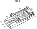
- FIG. 9 is a perspective view of the first detector 210 and the second detector 220.
- the first detector 210 and the second detector 220 are attached to each other by the magnetic force of the magnets 214 of the first detector 210 and the magnets 224 of the second detector 220.
- the magnetic force is set to an intensity that allows a relative movement between the first detector 210 and the second detector 220 when an external force is applied to the side surface of the second detector 220, for example, in the direction indicated by arrow F.
- the above-described relative movement is utilized when the second detector 220 detects a collision object such as a protrusion on the surface of the object 100 in a verification of position data of the object 100, which is described later.
- the flat springs 225a and 225b of the second detector 220 separate from the detection plates 215a and 215b of the first detector 210, and the contact detection unit 200 outputs an electric signal.
- the detection plates 215a and 215b are an example of a collision object detector.
- FIGS. 10A and 10B are schematic views illustrating an electrical connection of the contact detection unit 200.
- FIG. 10A is a schematic plan view illustrating the electrical connection of the contact detection unit 200
- FIG. 10B is a schematic front view illustrating the electrical connection of the contact detection unit 200.
- the first detector 210 is attached to the carriage 70 including the head 300 with the locks 211a and 211b (see FIG. 6 ).
- pin-shaped connection terminals 216a and 216b provided on the first detector 210 are fitted into jacks provided on the carriage 70, thereby electrically connecting the first detector 210 and the carriage 70.
- the second detector 220 is attached to the first detector 210 by the magnetic force of the magnets 214 and magnets 224.
- the detection plates 215a and 215b of the first detector 210 and the flat springs 225a and 225b of the second detector 220 are in contact with each other, and the first detector 210 and the second detector 220 are electrically connected to each other.
- the detection plate 215a of the first detector 210 is electrically connected to the connection terminal 216a via the push switch 213a and the push switch 213b.
- the other detection plate 215b is electrically connected to the connection terminal 216b via the push switch 213c and the push switch 213d.
- the push switches 213 and the detection plates 215a and 215b provided in the first detector 210 and the flat springs 225a and 225b provided in the second detector 220 are connected in series to form a series connection circuit.
- the series connection circuit is electrically conductive when the first detector 210 and the second detector 220 are attached to the carriage 70 at correct positions.
- the push switch 213 is turned on (conductive state) when not pressed and turned off (non-conductive state) when pressed.
- the contact detection unit 200 detects that the first detector 210 and the second detector 220 are at correct positions, and when the push switch 213 is in the non-conductive state, the contact detection unit 200 detects that the first detector 210 or the second detector 220 is not at a correct position.
- the configuration of the detector is not limited to the above-described embodiment.
- a non-contact type detector such as an optical sensor may be used instead of the contact type detector such as the push switches 213 or the detection plates 215a and 215b.
- the number and arrangement of the detectors are not limited to the above-described embodiment. An appropriate number and arrangement may be adopted in accordance with the size and the like of the carriage 70 and the head 300.
- the liquid discharge apparatus 1000 includes the carriage70 and the contact detection unit 200.
- the carriage 70 has the nozzle 302 from which ink is discharged toward the object 100.
- the carriage 70 is movable along at least one of the X-axis and the Y-axis intersecting the X-axis, and movable along the Z-axis intersecting the X-axis and the Y-axis.
- the Z-axis is parallel to the direction in which the ink is discharged from the nozzle 302 toward the object 100.
- the contact detection unit 200 detects contact of the carriage 70 with the object 100.
- the contact detection unit 200 is detachably attached to the carriage 70. Accordingly, the carriage 70 can be prevented from being damaged while moving relative to the object 100.
- the carriage 70 includes a detection mechanism to detect the surface shape of the object 100 (e.g., presence or absence of a collision object or the like) on the downstream side in a movement direction of the carriage 70.
- the detection mechanism may cause the carriage 70 to upsize, resulting in the liquid discharge apparatus 1000 upsizing.
- the contact detection unit 200 as the detection mechanism is detachably attached to the carriage 70, thereby preventing the carriage 70 from upsizing.
- the contact detection unit 200 includes the push switches 213 that detect the position of the object 100 relative to the carriage 70 (i.e., position detection).
- the contact detection unit 200 further includes the detection plates 215a and 215b that detect a collision object on the object 100 with which the carriage 70 may collide (i.e., collision object detection).
- collision object detection i.e., collision object detection
- the contact detection unit 200 includes the first detector 210 detachably attached to the carriage 70 and the second detector 220 detachably attached to the first detector 210, and implements at least one of the position detection and the collision object detection in response to the movement of the first detector 210 and the second detector 220.
- the second detector 220 is movable parallel to the movement direction of the carriage 70 relative to the first detector 210.
- the single contact detection unit 200 can implement different types of detection (i.e., the position detection and the collision object detection). That is, the contact detection unit 200 detects contact of the carriage 70 with the object 100 in the position detection and the collision object detection.
- the first detector 210 and the second detector 220 are attached to each other by the magnets 214 and 224.
- the second detector 220 can be easily positioned relative to the first detector 210.
- the push switch 213 operates (i.e., turns on and off to detect the position of the object 100) as the second detector 220 moves relative to the first detector 210 along the Z-axis, and the detection plates 215a and 215b operate (i.e. separate from the flat springs 225a and 225b to detect a collision object on the object 100) as the second detector 220 moves relative to the first detector 210 along at least one of the X-axis and the Y-axis.
- the push switches 213 and the flat springs 225a and 225b forms the series connection circuit.
- the contact detection unit 200 When the second detector 220 does not move along any of the X-axis, the Y-axis, and the Z-axis, the contact detection unit 200 outputs a signal indicating that the series connection circuit is in an electrically conductive state.
- the liquid discharge apparatus 1000 can detect the attachment state of the first detector 210 and the second detector 220 to the carriage 70.
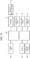
- FIG. 11 is a block diagram of a portion of the liquid discharge apparatus 1000 related to movement control of the carriage 70.
- the liquid discharge apparatus 1000 includes the carriage 70, the X-direction driver 72, the Y-direction driver 82, the Z-direction driver 92, the contact detection unit 200, a controller 500, a storage unit 501, a display 502, and a control panel 503.
- the carriage 70 is movable relative to the object 100 along the X-axis, Y-axis, and Z-axis.
- the carriage 70 includes the head 300 (see FIG. 1 ) that discharges ink toward the object 100.
- the X-direction driver 72 drives the carriage 70 along the X-axis based on an instruction from the controller 500.
- the Y-direction driver 82 drives the carriage 70 along the Y-axis based on an instruction from the controller 500.
- the Z-direction driver 92 drives the carriage 70 along the Z-axis based on an instruction from the controller 500.
- the contact detection unit 200 is detachaby attachable to the carriage 70. Before the carriage 70 discharges ink to the object 100 (i.e., ink discharge), the position of the object 100 may be measured (i.e., position measurement), and position data acquired in the position measurement may be verified (i.e., verification of the position data).
- the contact detection unit 200 is attached to the carriage 70 in the position measurement and in the verification of the position data.
- the above-described series connection circuit is formed, and the signal output from the contact detection unit 200 is transmitted to the controller 500 via the carriage 70.
- the controller 500 includes a central processing unit (CPU) and a read-only memory (ROM).
- the CPU controls the entire liquid discharge apparatus 1000.
- the ROM stores programs, which include a program to cause the CPU to perform the control of a drawing operation, for example, and other fixed data.
- the controller 500 further includes a random access memory (RAM) and an interface (I/F).
- the RAM temporarily stores drawing data and the like.
- the I/F is used when the controller 500 receives drawing data and the like from a host such as a personal computer (PC) to transmits data and signals.
- the controller 500 is an example of a control unit.
- the controller 500 stores and reads the detection result of the contact detection unit 200 in and from the storage unit 501.
- the controller 500 causes the X-direction driver 72, the Y-direction driver 82, and the Z-direction driver 92 to move the carriage 70 along the X-axis, the Y-axis, and the Z-axis.
- the controller 500 controls the ink discharge from the head 300 mounted on the carriage 70. Further, when an abnormality occurs in the operations of the carriage 70 and the head 300, the controller 500 displays information indicating the abnormality to a user on the display 502.
- the controller 500 receives an instruction from the control panel 503 and executes a process corresponding to the instruction.
- the storage unit 501 stores the position data (three dimensional coordinate data) in the position measurement, data in the verification of the position data, and the like from the contact detection unit 200.
- the display 502 displays the information indicating the abnormality to the user.
- the control panel 503 is used to input a value (coordinates) for specifying a drawing area 100a (see FIG. 12 ) where ink is discharged onto the object 100, a moving speed of the carriage 70, a distance between the head 300 and the object 100, and the like.
- the three dimensional coordinate data indicating the surface shape of the object 100 can be designated on the control panel 503. Note that the display 502 and the control panel 503 may be combined into one screen with a touch panel or the like.
- FIG. 12 is a schematic diagram illustrating a relation between the object 100 and the drawing area 100a.
- the object 100 has various sizes and shapes, and the positional relation between the liquid discharge apparatus 1000 and the object 100 changes depending on the installation state. Therefore, prior to the ink discharge to the object 100, the liquid discharge apparatus 1000 acquires the position data of the surface of the object 100.
- the coordinate data indicates X and Y coordinates, but is not limited thereto.
- the liquid discharge apparatus 1000 may be inclined with respect to the object 100, or a collision object such as a protrusion may be present on the surface of the object 100. Therefore, the coordinate data preferably includes three dimensional coordinates including the Z-direction component.
- the drawing area 100a is a range in which the carriage 70 of the liquid discharge apparatus 1000 moves. Although the drawing area 100a is the range in which the carriage 70 moves, an image is not necessarily drawn on the entire surface of the drawing area 100a. Multiple drawing areas, in which the carriage 70 can move, may be present in the same object 100.
- position data of the collision object is stored in the storage unit 501.
- the collision object when the object 100 is a body of a truck, a reinforcing rib of the body corresponds to the collision object.
- FIGS. 13A and 13B are schematic views for explaining the position measurement.
- FIG. 13A is a plan view illustrating a state in which the contact detection unit 200 is separated from the object 100
- FIG. 13B is a plan view illustrating a state in which the contact detection unit 200 contacts the object 100.
- the liquid discharge apparatus 1000 Prior to the ink discharge to the object 100, the liquid discharge apparatus 1000 performs the position measurement to acquire position data of the drawing area 100a of the object 100 and grasp the surface shape of the drawing area 100a.
- the carriage 70 at the standby position on the Z-axis is moved toward the object 100 in the positive Z-axis direction.
- the second detector 220 moves in the negative Z-axis direction relative to the carriage 70.
- the second detector 220 presses the first detector 210 in the negative Z-axis direction.
- the first detector 210 presses the push switch 213 toward the carriage 70. Accordingly, the push switch 213 is operated, and the contact detection unit 200 detects the position of the surface of the object 100.
- the position data of the carriage 70 is stored in the storage unit 501 of the liquid discharge apparatus 1000.
- the above-described operation is performed multiple times from the drawing start position P1 to the drawing end position P2 in the drawing area 100a to acquire data indicating the surface shape of the drawing area 100a.
- FIG. 14 is a schematic diagram illustrating an example of an electrical connection of the contact detection unit 200.
- the push switches 213 and the detection plates 215a and 215b provided in the first detector 210 and the flat springs 225a and 225b provided in the second detector 220 form the series connection circuit.
- FIG. 14 illustrates a state in which the push switch 213d among the four push switches 213 detects the position of the object 100.
- the position and the number of the push switches 213 to be operated change depending on the surface shape of the object 100.
- the push switch 213 is turned off by the pressing force when the surface position of the object 100 has been detected.
- the series connection circuit is in the non-conductive state.
- the coordinate data which indicates the surface position of the object 100 at the current position, is stored in the storage unit 501.
- FIG. 15 is a schematic diagram illustrating a case in which coordinate data of the object 100 is automatically acquired.
- a user sets X grid lines 100b and Y grid lines 100c with certain setting values.
- the setting values include designation of the number of grid lines or the interval between grid lines.
- the liquid discharge apparatus 1000 performs the position measurement of the surface of the object 100 at the intersections of the X grid lines 100b and the Y grid lines 100c, and automatically acquires coordinate data (three dimensional coordinate data of X, Y, and Z).
- the user can obtain the coordinate data at fine intervals or at coarse intervals according to the setting value of the grid lines set by the user.
- the user may set only the drawing start position P1 and the grid lines, and the drawing end position P2 may be determined in accordance with the grid lines.
- the liquid discharge apparatus 1000 may perform the position measurement of the certain portion having the X and Y coordinates specified by the user, and add position data in the position measurement to the coordinate data.
- FIGS. 16A to 16D are schematic views illustrating a positional relation between the carriage 70 and the surface shape of the object 100 in the position measurement.
- FIG. 16A illustrates a case in which the surface of the object 100 is inclined
- FIGS. 16B, 16C and 16D illustrate a case in which a protrusion is present on the surface of the object 100.
- the liquid discharge apparatus 1000 may erroneously recognize a protrusion or a step between the two points of the coordinates (Xm, Ym, Zm) and the coordinates (Xn, Yn, Zn) as illustrated in FIG. 16B as an inclined surface.
- the liquid discharge apparatus 1000 may overlooks the protrusion. Further, as illustrated in FIG. 16D , even when the liquid discharge apparatus 1000 recognizes the presence of a protrusion in the position measurement, the carriage 70 may fail to avoid the protrusion and may collide with the protrusion.
- the carriage 70 is different between the position measurement and the ink discharge.
- the carriage 70 In the position measurement, the carriage 70 is moved along the X-axis and Y-axis. After reaching the measurement point, the carriage 70 is moved along the Z-axis.
- the carriage 70 In the ink discharge to the object 100, the carriage 70 is continuously moved along in the X-axis, the Y-axis, and the Z-axis while keeping the distance between the object 100 and the carriage 70 constant.
- the liquid discharge apparatus 1000 executes a process in which position data in the position measurement is verified after the position measurement and before the ink discharge (i.e., the verification of the position data).
- the carriage 70 is moved relative to the object 100 in accordance with the coordinate data indicating the movement trajectory of the carriage 70 obtained based on the position data in the position measurement to check the presence or absence of a protrusion or the like overlooked in the position measurement.
- the movement of the carriage 70 in the verification is the same as the movement in the ink discharge except that ink is not discharged. Therefore, if a new protrusion or the like is not present in the verification, failure of drawing does not occur in the actual ink discharge. The verification is described in further detail later.
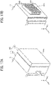
- FIGS. 17A and 17B are schematic perspective views illustrating a relation between the detection face 220a of the contact detection unit 200 and the liquid discharge face (nozzle face) 302a.
- FIG. 17A illustrates the detection face 220a of the contact detection unit 200
- FIG. 17B illustrates the liquid discharge face (nozzle face) 302a of the nozzles 302 in the carriage 70.
- the contact detection unit 200 attached to the carriage 70 includes the first detector 210 and the second detector 220. The position of the carriage 70 relative to the object 100 is measured by the contact of the detection face 220a of the second detector 220 with the object 100.
- the carriage 70 has the nozzle 302, which is an example of a liquid discharge port, at a portion to which the contact detection unit 200 is attached.
- the heads 300 having a plurality of nozzles 302 is mounted on the carriage 70.
- the plurality of nozzles 302 forms the liquid discharge face (nozzle face) 302a.
- the heads 300 includes six heads arranged along the Y-axis, and each head has eight nozzles 302 along the X-axis. That is, the head 300 has 48 nozzles 302.
- the surface formed by the 48 nozzles 302 is defined as the liquid discharge face (nozzle face) 302a.
- the surface having a shape corresponding to the exterior of the head 300 may be defined as the liquid discharge face (nozzle face) 302a.
- the number and arrangement of the nozzles 302 are not limited to the above-described embodiment.
- the nozzles 302 may be arranged in a row in the vertical or horizontal direction instead of the two dimensional arrangement in the vertical and horizontal directions as illustrated. Further, the number of nozzles 302 may be one instead of two or more.
- the detection face 220a of the second detector 220 is larger in area than the liquid discharge face 302a of the carriage 70.
- the height (along the Y-axis), the width (along the X-axis), and the thickness (along the Z-axis) of the detection face 220a may be appropriately changed in accordance with the surface shape or the surface state of the object 100 to be measured.
- the area of the detection face 220a refers to the area of a projection surface of the detection face 220a projected onto the liquid discharge face 302a from the object 100 side along the Z-axis. For example, when the detection face 220a is larger in area than the liquid discharge face 302a as illustrated in FIGS. 17A and 17B , the liquid discharge face 302a falls within the projection surface of the detection face 220a from the object 100 side.
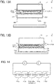
- FIGS. 18A to 18C are schematic views of the contact detection unit 200 having the detection face 220a of different area.
- FIG. 18A illustrates a case in which the detection face 220a of the second detector 220 is larger in area than the liquid discharge face 302a.
- FIG. 18B illustrates a case in which the detection face 220a of the second detector 220 is equivalent in area to the liquid discharge face 302a.
- FIG. 18C illustrates a case in which the detection face 220a of the second detector 220 is smaller in area than the liquid discharge face 302a.
- the position detection can be performed in a short time when the object 100 has a substantially flat surface.
- the position detection can be performed at an interval corresponding to the width of the head 300.
- the position detection of the object 100 can be finely performed. Therefore, even when the object 100 has a collision object such as a protrusion or the like at a narrow interval, the collision object can be prevented from being overlooked.
- the detection face 220a that contacts the object 100 to detect the position of the object 100 relative to the carriage 70 has a larger area than the liquid discharge face 302a of the nozzles 302. As a result, a wide range can be detected at a time, and the position detection can be completed in a short time for the flat object 100.
- the detection face 220a that contacts the object 100 to detect the position of the object 100 relative to the carriage 70 has an area equivalent to the area of the liquid discharge face 302a of the nozzles 302. As a result, the position can be accurately detected at an interval corresponding to the width of the head 300 used for actual ink discharge.
- the detection face 220a that contacts the object 100 to detect the position of the object 100 relative to the carriage 70 has a smaller area than the liquid discharge face 302a of the nozzles 302. As a result, the position of the object 100 can be finely detected, thereby preventing a collision object on the object 100 from being overlooked.
- the liquid discharge apparatus 1000 executes the process of verifying the position data in the position measurement after the position measurement and before the ink discharge.
- the carriage 70 is moved relative to the object 100 in accordance with the coordinate data indicating the movement trajectory of the carriage 70 obtained based on the position data in the position measurement to check the presence or absence of a protrusion or the like overlooked in the position measurement.
- the movement of the carriage 70 in the verification is the same as the movement in the ink discharge except that ink is not discharged.
- FIG. 19 is a flowchart illustrating the verification of the position data.
- the carriage 70 to which the contact detection unit 200 is attached moves to the drawing start position P1 set by the user on the control panel 503 (step SI).
- the carriage 70 starts moving from the drawing start position P1 under control of the controller 500 of the liquid discharge apparatus 1000 (step S2).
- the controller 500 determines three dimensional (X, Y, and Z) coordinates indicating the movement trajectory of the carriage 70 based on the position data detected by the position detector (the push switches 213) in the position measurement. Then, the controller 500 moves the carriage 70 toward the drawing end position P2 set by the user on the control panel 503 in accordance with the three dimensional coordinate data. While the carriage 70 moves, the contact detection unit 200 attached to the carriage 70 detects a protrusion of the object 100 (step S3). When the contact detection unit 200 does not detect a protrusion while the carriage 70 moves from the drawing start position P1 to the drawing end position P2, the carriage 70 stops moving (step S4). Detailed description of a section A of the flowchart is deferred.
- the controller 500 of the liquid discharge apparatus 1000 displays that the verification is completed on the display 502 to indicate the completion of the verification to a user (step S5). Then, the carriage 70 moves to the drawing start position P1 (step S6). The carriage 70 that has moved to the drawing start position P1 stands by in preparation for the ink discharge to the object 100.
- the controller 500 of the liquid discharge apparatus 1000 records position data indicating the position of the protrusion (step S7).
- the position data is stored in the storage unit 501 of the liquid discharge apparatus 1000 to record the position of the protrusion.
- the controller 500 of the liquid discharge apparatus 1000 causes the Z-direction driver 92 to move the carriage 70 in the negative Z-axis direction, and the carriage 70 moves to the standby position on the Z-axis (step S8). Thus, the carriage 70 is retracted away from the protrusion.
- the controller 500 of the liquid discharge apparatus 1000 stops the X-direction driver 72 and the Y-direction driver 82 to stop the carriage 70 (step S9).
- the controller 500 of the liquid discharge apparatus 1000 displays the position data of the protrusion on the display 502 to notify the user (step S10). Then, a display screen of the control panel 503 transitions to the position measurement screen (step S11). On the position measurement screen, the user adds the position data of the protrusion to the original position data in the position measurement as appropriate.
- the position data of the protrusion may be manually added by the user after the user confirms the state of the object 100 and determines whether to add the position data. Alternatively, the position data may be automatically added by the liquid discharge apparatus 1000.
- step S3 when the contact detection unit 200 detects a protrusion in step S3, the position data of the protrusion is added to the original position data in the position measurement, and the process is executed again from step S1.
- the contact detection unit 200 does not detect the protrusion while the carriage 70 moves from the drawing start position P1 to the drawing end position P2, the verification is completed, and the process proceeds to steps of actually discharging ink toward the object 100. After the verification is completed, the process does not necessarily proceed to the ink discharge. After the first verification, the position measurement may be performed again. By repeating the position measurement of the object 100 and the verification of the position data, three dimensional coordinate data of the object 100 can be acquired more accurately, and the ink discharge suitable for the shape of the object 100 can be performed.
- the three dimensional coordinate data once created by the position measurement and the verification is stored in the storage unit 501 of the liquid discharge apparatus 1000. Accordingly, the three dimensional coordinate data is available when the ink discharge is performed on the object 100 having the same shape. In addition, even when the relative position between the liquid discharge apparatus 1000 and the object 100 is changed, the coordinate data regarding the shape of the object 100 can be used. Therefore, when the object 100 has the same shape, the user can omit at least a part of the verification by using the position data in the position measurement.
- the second detector 220 detects a protrusion as the protrusion of the object 100 collides with the second detector 220 of the contact detection unit 200 (detailed description is deferred).
- the protrusion may be detected not by physical contact as described above but also by optical detection using laser light or by image processing.
- An object to be detected is not limited to the protrusion of the object 100.
- the detection is performed by optical or image processing as described above, arbitrary portion on the object 100 can be detected. For example, a hole provided in the object 100, or a place where drawing is intentionally avoided (e.g., an image already drawn or a masking portion) can be detected as a detection target.
- FIG. 20 is a schematic diagram illustrating a positional relation between the carriage 70 at the time of the verification and at the time of the ink discharge.
- the carriage 70 depicted by the solid line indicates the position relative to the object 100 in the verification of the position data.
- the carriage 70 is shifted by a distance L1 in the positive Z-axis direction as depicted by the broken line.
- the contact detection unit 200 is attached to the carriage 70. Therefore, the distance L1 is set in consideration of the thickness of the contact detection unit 200 along the Z-axis.
- the controller 500 moves the carriage 70 to the position corrected by the distance L1 and cause the carriage 70 to discharge ink.
- the movement trajectory and the moving speed of the carriage 70 in the verification of the position data are set to the same as the setting in the ink discharge to the object 100.
- the liquid discharge apparatus When a liquid discharge apparatus discharges ink to an object such as a body of a car, a truck, or an aircraft, the liquid discharge apparatus is a large system. Accordingly, the rails and the apparatus frame may be bent due to the weights of the carriage 70, the X-axis rail 101, Y-axis rail 102, and Z-axis rail 103 and the inertia force caused by the movement of the carriage 70. Therefore, the verification of the position data is preferably performed in accordance with the movement of the carriage 70 when the ink is actually discharged to the object 100. If the setting of the movement trajectory and the moving speed of the carriage 70 in the verification of the position data is the same as the setting in the ink discharge to the object 100, the position data along the movement trajectory of the carriage 70 can be accurately verified.
- FIGS. 21A and 21B are schematic views illustrating an example in which a protrusion is detected in the verification.
- FIG. 21A illustrates a state before the protrusion is detected
- FIG. 21B illustrates a state in which the protrusion is detected.
- a description is given below of the verification when a protrusion 110 overlooked in the position measurement is present on the surface of the object 100.
- the second detector 220 is attached to the first detector 210 at the correct position. Therefore, the detection plates 215a and 215b of the first detector 210 and the flat springs 225a and 225b of the second detector 220 contact each other, and the series connection circuit is in the electrically conductive state.
- the second detector 220 collides with the protrusion 110 and does not further move in the positive X-axis direction. Since the second detector 220 is movable parallel to the movement direction of the carriage 70 relative to the first detector 210, the second detector 220 slides in the direction opposite to the movement direction of the carriage 70 due to the collision with the protrusion 110. Accordingly, the detection plates 215a and 215b of the first detector 210 are separated from the flat springs 225a and 225b of the second detector 220, and the series connection circuit is in the non-conductive state. After the protrusion 110 is detected, the process is executed based on steps illustrated in FIG. 19 .
- FIGS. 22A and 22B are schematic diagrams illustrating an example of an electrical connection of the series connection circuit.
- FIG. 22A illustrates a state in which the contact detection unit 200 is correctly attached to the carriage 70
- FIG. 22B illustrates a state in which the second detector 220 of the contact detection unit 200 is not correctly attached.
- FIG. 22B illustrates a state in which the protrusion 110 illustrated in FIG. 21B is detected.
- FIG. 23 is a schematic diagram illustrating an example of the movement trajectory of the carriage 70.
- the carriage 70 moves from the drawing start position P1 in the positive X-axis direction and reaches the return position. Then, the carriage 70 moves by a movement amount La in the positive Y-axis direction (i.e., line feed). After the line feed, the carriage 70 moves in the negative X-axis direction and reaches the other return position. Then, the carriage 70 again moves by the movement amount La in the positive Y-axis direction (i.e., line feed). While this movement is repeated, the carriage 70 moves to the drawing end position P2 along the movement trajectory indicated by the arrow.
- a movement amount La in the positive Y-axis direction i.e., line feed
- the carriage 70 may overrun out of the drawing area 100a in the last line. If the carriage 70 moves out of the drawing area 100a, when the contact detection unit 200 detects a protrusion, the liquid discharge apparatus 1000 does not distinguish whether the protrusion is detected inside the drawing area 100a or outside the drawing area 100a.
- the carriage 70 preferably moves from the drawing start position P1 to the drawing end position P2 without moving out of the drawing area 100a. Therefore, in the present embodiment, a movement amount Lb of the carriage 70 in the last line is smaller than the movement amount La, and the movement trajectory of the carriage 70 is controlled so that the position of the carriage 70 in the last line coincides with the drawing end position P2.
- the movement setting such as the movement amounts La and Lb is the same in the verification of the position data and the ink discharge to the drawing object 100.
- the movement amount La and the movement amount Lb may be equalized so that the carriage 70 finally falls within the drawing area 100a.
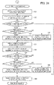
- FIG. 24 is a flowchart illustrating the section A of the verification flow illustrated in FIG. 19 in detail.
- the liquid discharge apparatus 1000 determines the number of times and amount of movement of the carriage 70 while checking the remaining amount of the drawing area 100a along the Y-axis.
- the controller 500 drives the X-direction driver 72 to move the carriage 70 from the drawing start position P1 in the positive X-axis direction as illustrated in FIG. 23 (step S21). As the carriage 70 moves in the positive X-axis direction, a counter that counts the number of moves of the carriage 70 along the X-axis adds 1 to a count value (step S22). When the carriage 70 reaches the end point (return position) on the positive side along the X-axis, the controller 500 determines whether the drawing area 100a remains along the Y-axis (step S23).
- the controller 500 determines whether the remaining amount is equal to or greater than the movement amount La (step S24).
- the movement amount La corresponds to the height (length) of the carriage 70 (liquid discharge face 302a) along the Y-axis. Therefore, the terms "the remaining amount of the drawing area 100a along the Y-axis is equal to or greater than the movement amount La" means that a line feed in the positive Y-axis direction can be performed by the height of the carriage 70.
- the controller 500 drives the Y-direction driver 82 to move the carriage 70 by the movement amount La in the positive Y-axis direction (step S25).
- the controller 500 drives the Y-direction driver 82 to move the carriage 70 by the movement amount Lb in the positive Y-axis direction (step S26).
- the movement amount Lb is smaller than the movement amount La, and is set so that the carriage 70 coincides with the drawing end position P2.
- step S27 the controller 500 drives the X-direction driver 72 to move the carriage 70 in the negative X-axis direction.
- step S28 the counter that counts the number of moves of the carriage 70 along the X-axis adds 1 to the count value (step S28).
- step S29 the controller 500 determines whether the drawing area 100a remains along the Y-axis.
- step S33 the controller 500 determines whether the remaining amount is equal to or greater than the movement amount La (step S30).
- the controller 500 drives the Y-direction driver 82 to move the carriage 70 by the movement amount La in the positive Y-axis direction (step S31).
- the controller 500 drives the Y-direction driver 82 to move the carriage 70 by the movement amount Lb in the positive Y-axis direction (step S32).
- step S31 or step S32 After the carriage 70 moves in the positive Y-axis direction in step S31 or step S32, the process returns to the step S21, and the controller 500 repeats the above-described flow until the remaining amount of the drawing area 100a runs out.
- the controller 500 controls the carriage 70 within the drawing area 100a so that the carriage 70 does not move out of the drawing area 100a. Therefore, the liquid discharge apparatus 1000 can accurately perform the position measurement, the verification, and the ink discharge in a determined drawing area 100a.
- FIG. 25 is a schematic view illustrating an example of the display screen of the control panel 503 of the liquid discharge apparatus 1000.
- a user can input X and Y coordinate data to determine the drawing start position P1 and the drawing end position P2 of the drawing area (print range) 100a, and select the moving speed of the carriage 70 on the control panel 503.
- the user can designate the three dimensional coordinate data (body data) indicating the surface shape of the object 100 and input the distance (set gap) between the head 300 and the object 100 on the control panel 503.
- FIG. 26 is a schematic view of a fall prevention component that prevents the second detector 220 from falling off the contact detection unit 200.
- the contact detection unit 200 includes the first detector 210 and the second detector 220 that are attached to each other by the magnetic force of the magnets 214 and 224 as described above. Accordingly, if the second detector 220 moves relative to the first detector 210 by a distance equal to or greater than the size of the magnets 214 and 224 due to the detection of the protrusion, the second detector 220 may fall from the first detector 210 and may be damaged.
- the first detector 210 and the second detector 220 may be coupled to each other by a string-shaped component 230.
- the string-shaped component 230 includes a string, a wire, a chain, and the like. Note that the string, the wire, and the chain are an example of the fall prevention component.
- the string-shaped component 230 that prevents the second detector 220 from falling from the first detector 210 is provided between the first detector 210 and the second detector 220. Accordingly, even when the second detector 220 is detached from the first detector 210, the string-shaped component 230 can prevent the second detector 220 from falling off and from being damaged or lost.
- FIG. 27 is a schematic view of a liquid discharge apparatus 1000 according to a variation of the present disclosure.
- FIG. 28 is an enlarged perspective view of the liquid discharge apparatus 1000 according to the variation.
- the liquid discharge apparatus 1000 includes a linear rail 404 and a multi-articulated robot 405.
- the linear rail 404 guides a carriage 1 as a liquid discharge unit that reciprocally and linearly moves along the linear rail 404.
- the multi-articulated robot 405 appropriately moves the linear rail 404 to a predetermined position and holds the linear rail 404 at the predetermined position.
- the multi-articulated robot 405 includes a robot arm 405a that is freely movable like a human arm by a plurality of joints.
- the multi-articulated robot 405 can freely move a distal end of the robot arm 405a and arrange the distal end of the robot arm 405a at an accurate position.
- An industrial robot of a six-axis control-type having six axes (six joints) can be used as the multi-articulated robot 405, for example.
- the multi-articulated robot 405 of the six-axis control-type it is possible to previously teach data related to a movement of the multi-articulated robot 405.
- the multi-articulated robot 405 can accurately and quickly position the linear rail 404 at a predetermined position facing an object 100 (an aircraft in the present embodiment).
- the number of axes of the multi-articulated robot 405 is not limited to six, and a multi-articulated robot having an appropriate number of axes such as five axes or seven axes can be used.
- the robot arm 405a of the multi-articulated robot 405 includes a fork-shaped support 424 bifurcated into two.
- a vertical linear rail 423a is attached to a tip of a left branch 424a of the support 424, and a vertical linear rail 423b is attached to a tip of a right branch 424b of the support 424.
- the vertical linear rail 423a and the vertical linear rail 423b are parallel to each other. Further, both ends of the linear rail 404 that movably holds the carriage 1 are supported by the vertical linear rails 423a and 423b.
- the carriage 1 includes, for example, the head 300 described with reference to FIG.
- a plurality of heads 300 that discharges inks of respective colors (e.g., yellow, magenta, cyan, black, and white), or a head 300 having a plurality of nozzle rows.
- the inks of respective colors are respectively supplied from ink tanks 330 to the heads 300 or the nozzle rows of the head 300 of the carriage 1.
- the multi-articulated robot 405 moves the linear rail 404 to a desired drawing area of the object 100, and the heads 300 are driven to draw images on the object 100 while moving the carriage 1 along the linear rail 404 according to drawing data.
- the liquid discharge apparatus 1000 ends drawing of one line, the liquid discharge apparatus 1000 causes the vertical linear rails 423a and 423b of the multi-articulated robot 405 to move the heads 300 of the carriage 1 from the one line to the next line.
- the liquid discharge apparatus 1000 repeats the above-described operation to draw images on the desired drawing area of the object 100.
- the contact detection unit 200 is attached to the carriage 1 as a liquid discharge unit.
- the liquid discharge apparatus 1000 performs the ink discharge after the position measurement and the verification, thereby obtaining the above-described effect according to the present disclosure.
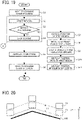
- the present disclosure can also be applied to an unmanned aerial vehicle 6000 such as a drone illustrated in FIG. 29 .
- the unmanned aerial vehicle 6000 includes a detector 610 such as a rangefinder mounted thereon and controls the position of the unmanned aerial vehicle 6000 based on a detection result of the detector 610.
- the unmanned aerial vehicle 6000 further includes a liquid discharge unit 620 including a head that discharges liquid such as ink. Liquid stored in a liquid tank 630 is supplied to the liquid discharge unit 620 via a tube 640.
- the unmanned aerial vehicle 6000 causes the head of the liquid discharge unit 620 to discharge the liquid toward an object 100 (a wall of a building in the present embodiment) based on the position controlled as described above to applies the liquid to an area to be painted P of the object 100.
- the present disclosure can also be applied to an unmanned vehicle 7000 such as a wall climbing robot illustrated in FIG. 30 .
- the unmanned vehicle 7000 drives rollers 710 while sucking the object 100 (the wall of the building in the present embodiment) at the bottom of the unmanned vehicle 7000 to move on the object 100.
- the unmanned vehicle 7000 includes a liquid discharge unit 720 including a head that discharges liquid such as ink. Liquid stored in a liquid tank 730 is supplied to the liquid discharge unit 720 via a tube 740.
- the unmanned vehicle 7000 causes the head of the liquid discharge unit 720 to discharge the liquid toward the object 100 (the wall of the building in the present embodiment) to applies the liquid to an area to be painted P of the object 100.
- the present disclosure can also be applied to a coating robot 8000 illustrated in FIG. 31 that coats, for example, a body of an automobile.
- the coating robot 8000 includes a robot arm 810 that is freely movable like a human arm by a plurality of joints, and further includes a liquid discharge unit 820 including a head that discharges liquid at a distal end of the robot arm 810.
- the robot arm 810 includes a three-dimensional (3D) sensor 830 near of the liquid discharge unit 820.
- the coating robot 8000 having an appropriate number of axes such as five, six, or seven axes can be used.
- the coating robot 8000 detects the position of the liquid discharge unit 820 relative to the object 100 (the body of the automobile in the present embodiment) by the 3D sensor 830, and moves the robot arm 810 based on the detection result to coat the object 100.
- FIG. 32 is a schematic view of the apparatus 9000 that manufactures a negative electrode used for an electrochemical element such as a primary battery, a secondary battery, or a capacitor.
- This apparatus 9000 includes a liquid discharge unit 920 including a head that discharges liquid. The liquid is discharged to an object 100 (a negative electrode substrate in the present embodiment) on a stage 910 by an inkjet method.
- a liquid tank 930 stores a liquid composition 900A for forming a negative electrode composite layer 900, and the liquid composition 900A is supplied from the liquid tank 930 to the liquid discharge unit 920 via a tube 940.
- the liquid composition 900A may be circulated in the apparatus 9000.
- an external tank 950 is connected to the liquid tank 930 via a valve 960A
- the liquid tank 930 is connected to the liquid discharge unit 920 via a valve 960B.
- the liquid discharge unit 920 is connected to a pump 970 via a valve 960C
- the pump 970 is connected to the liquid tank 930.
- the apparatus 9000 controls the flow of the liquid composition 900A with the pump 970 and the valves 960B and 960C to circulate the liquid composition 900A, which is stored in the liquid tank 930, in the apparatus 9000.
- the apparatus 9000 includes the external tank 950 and the valve 960A.
- the apparatus 9000 controls the valve 960A to supply the liquid composition 900A from the external tank 950 to the liquid tank 930 of the apparatus 9000 when the liquid composition 900A to be discharged decreases.
- the object 100 the negative electrode substrate
- the stage 910 may be moved relative to the liquid discharge unit 920, or the liquid discharge unit 920 may be moved relative to the object 100.
- the stage 910 heats and dries the liquid composition 900A on the object 100, thereby forming the negative electrode composite layer 900.
- drying is not limited to heating on the stage 910.
- a drying device provided separately from the stage 910 may be used.
- the drying device is not particularly limited and may be appropriately selected as long as the drying device does not directly contact the liquid composition 900A.
- a resistance heater, an infrared heater, a fan heater, or a blower can be used as the drying device.
- a plurality of drying devices may be provided.
- the negative electrode used for the electrochemical element can also be manufactured using an apparatus 9500 illustrated in FIG. 34 .
- a band-shaped object 100 (the negative electrode substrate in the present embodiment) made of stainless steel, copper or the like is wound around a cylindrical core, and the object 100 is loaded on a feed roller 980A and a winding roller 980B such that the surface of the object 100 on which the negative electrode composite layer 900 is to be formed faces upward.
- the feed roller 980A and the winding roller 980B rotate counterclockwise, the object 100 moves from right to left in FIG. 34 .
- the liquid tank 930 stores the liquid composition 900A for forming the negative electrode composite layer 900, and the liquid composition 900A is supplied from the liquid tank 930 to the liquid discharge unit 920 via the tube 940.
- the liquid discharge unit 920 is disposed above the object 100 between the feed roller 980A and the winding roller 980B.
- a plurality of liquid discharge units 920 may be provided in a direction substantially parallel or substantially perpendicular to the conveyance direction of the object 100.
- the feed roller 980A and the winding roller 980B convey the object 100 carrying the liquid composition 900A to a drying device 990.
- the liquid composition 900A on the object 100 is dried to form the negative electrode composite layer 900, thereby forming a negative electrode 90 in which the negative electrode composite layer 900 is bonded onto the object 100 as the negative electrode substrate.
- the negative electrode 90 is cut into a desired size by punching or the like.
- the drying device 990 is not particularly limited and may be appropriately selected as long as the drying device 990 does not directly contact the liquid composition 900A.
- a resistance heater, an infrared heater, or a fan heater can be used as the drying device 990.
- the drying device 990 may be provided above or below the object 100, and a plurality of drying devices 990 may be provided.
- an inkjet method is preferable in that a liquid can be applied to an aimed portion of the object 100 below the liquid discharge unit 920.
- the inkjet method is preferable because the surfaces of the object 100 (the negative electrode substrate) and the negative electrode composite layer 900, which are in contact with each other, can be bonded to each other. Further, the inkjet method is preferable because the film thickness of the negative electrode composite layer 900 can be formed evenly.
- the apparatus that manufactures the negative electrode used for the electrochemical element has been described as an example, but the present disclosure can also be applied to an apparatus that manufactures a positive electrode.
- a positive electrode substrate is used as the object 100 instead of the negative electrode substrate, and a liquid composition for forming a positive electrode composite layer is used instead of the liquid composition 900A for forming the negative electrode composite layer 900.
- the liquid discharge apparatus 1000 includes the carriage70 (an example of a liquid discharge unit) and the contact detection unit 200 (an example of a contact detection unit).
- the carriage 70 has the nozzle 302 (an example of a liquid discharge port) from which ink (an example of a liquid) is discharged toward the object 100 (an example of an object on which an image is drawn).
- the carriage 70 is movable along at least one of the X-axis (an example of a first axis) and the Y-axis intersecting the X-axis (an example of a second axis intersecting the first axis), and movable along the Z-axis intersecting the X-axis and the Y-axis (an example of a third axis intersecting the first axis and the second axis).
- the Z-axis is parallel to the direction in which ink is discharged from the nozzle 302 toward the object 100.
- the contact detection unit 200 detects contact of the carriage 70 with the object 100.
- the contact detection unit 200 is detachably attached to the carriage 70.
- the liquid discharge apparatus 1000 can be provided that prevents the carriage 70 from being damaged while moving the carriage 70 relative to the object 100.
- the contact detection unit 200 includes the push switches 213 (an example of a position detector) that detect the position of the object 100 relative to the carriage 70 (i.e., position detection).
- the contact detection unit 200 includes the detection plates 215a and 215b (an example of a collision object detector) that detect a collision object on the object 100, which may collide with the carriage 70 (i.e., collision object detection).
- the position detection and the collision object detection can be performed with a simple configuration.
- the contact detection unit 200 includes the first detector 210 (an example of a first component) detachably attached to the carriage 70 and the second detector 220 (an example of a second component) detachably attached to the first detector 210, and performs at least one of the position detection and the collision object detection in response to movement of the first detector 210 and the second detector 220.
- the second detector 220 is movable parallel to a movement direction of the carriage 70 relative to the first detector 210.
- the single contact detection unit 200 can perform different types of detection (i.e., the position detection and the collision object detection).
- the first detector 210 and the second detector 220 are attached to each other by the magnets 214 and 224 (an example of a magnetic force).
- the second detector 220 can be easily positioned relative to the first detector 210.
- the contact detection unit 200 includes the push switches 213 and the detection plates 215a and 215b.
- the push switches 213 detect the position of the object 100 relative to the carriage 70 as the second detector 220 moves relative to the first detector 210 along the Z-axis.
- the detection plates 215a and 215b detect a collision object on the object 100 as the second detector 220 moves relative to the first detector 210 along at least one of the X-axis and the Y-axis.
- the push switches 213 and the detection plates 215a and 215b forms a series connection circuit.
- the contact detection unit 200 outputs a signal indicating that the series connection circuit is in an electrically conductive state.
- the liquid discharge apparatus 1000 can also detect the attachment state of the first detector 210 and the second detector 220 to the carriage 70.
- the contact detection unit 200 has the detection face 220a (an example of a detection face) that contacts the object 100 to detect a position of the object 100 relative to the carriage 70.
- the detection face 220a is larger in area than a liquid discharge face 302a (an example of a liquid discharge face) of the nozzles 302.
- a wide range can be detected at a time, and the position detection can be completed in a short time for the flat object 100.
- the contact detection unit 200 has the detection face 220a that contacts the object 100 to detect a position of the object 100 relative to the carriage 70.
- the detection face 220a is equivalent in area to a liquid discharge face 302a of the nozzles 302.
- the position of the object 100 can be accurately detected at an interval corresponding to the width of the head 300 used for actual ink discharge.
- the contact detection unit 200 has the detection face 220a that contacts the object 100 to detect a position of the object 100 relative to the carriage 70.
- the detection face 220a is smaller in area than a liquid discharge face 302a of the nozzles 302.
- the position of the object 100 can be finely detected, thereby preventing a collision object on the object 100 from being overlooked.
- the string-shaped component 230 (an example of a fall prevention component) that prevents the second detector 220 from falling from the first detector 210 is provided between the first detector 210 and the second detector 220.
- the string-shaped component 230 can prevent the second detector 220 from falling off and from being damaged or lost.
- Processing circuitry includes a programmed processor, as a processor includes circuitry.
- a processing circuit also includes devices such as an application specific integrated circuit (ASIC), a digital signal processor (DSP), a field programmable gate array (FPGA), and conventional circuit components arranged to perform the recited functions.
- ASIC application specific integrated circuit
- DSP digital signal processor
- FPGA field programmable gate array
Landscapes
- Engineering & Computer Science (AREA)
- Manufacturing & Machinery (AREA)
- Chemical & Material Sciences (AREA)
- Chemical Kinetics & Catalysis (AREA)
- Electrochemistry (AREA)
- General Chemical & Material Sciences (AREA)
- Ink Jet (AREA)
- Sampling And Sample Adjustment (AREA)
- Feeding, Discharge, Calcimining, Fusing, And Gas-Generation Devices (AREA)
Applications Claiming Priority (2)
| Application Number | Priority Date | Filing Date | Title |
|---|---|---|---|
| JP2020169112 | 2020-10-06 | ||
| JP2021144130A JP2022061472A (ja) | 2020-10-06 | 2021-09-03 | 液体吐出装置 |
Publications (3)
| Publication Number | Publication Date |
|---|---|
| EP3991978A2 true EP3991978A2 (de) | 2022-05-04 |
| EP3991978A3 EP3991978A3 (de) | 2022-07-06 |
| EP3991978B1 EP3991978B1 (de) | 2025-08-06 |
Family
ID=78085504
Family Applications (1)
| Application Number | Title | Priority Date | Filing Date |
|---|---|---|---|
| EP21201133.2A Active EP3991978B1 (de) | 2020-10-06 | 2021-10-06 | Flüssigkeitsausgabevorrichtung |
Country Status (2)
| Country | Link |
|---|---|
| US (1) | US11597221B2 (de) |
| EP (1) | EP3991978B1 (de) |
Cited By (1)
| Publication number | Priority date | Publication date | Assignee | Title |
|---|---|---|---|---|
| EP4435879A1 (de) * | 2023-03-21 | 2024-09-25 | Prime Planet Energy & Solutions, Inc. | Verfahren zur herstellung einer energiespeichervorrichtung |
Families Citing this family (4)
| Publication number | Priority date | Publication date | Assignee | Title |
|---|---|---|---|---|
| JP7753800B2 (ja) * | 2021-10-28 | 2025-10-15 | セイコーエプソン株式会社 | 印刷装置 |
| JP2023128410A (ja) | 2022-03-03 | 2023-09-14 | 株式会社リコー | 液滴吐出ヘッドおよび液滴吐出装置 |
| JP2024102488A (ja) * | 2023-01-19 | 2024-07-31 | セイコーエプソン株式会社 | 印刷装置および印刷方法 |
| IT202300007227A1 (it) * | 2023-04-14 | 2024-10-14 | Spider Jet S R L | Stampante per manufatti lastriformi |
Citations (1)
| Publication number | Priority date | Publication date | Assignee | Title |
|---|---|---|---|---|
| JP2018001715A (ja) | 2016-07-08 | 2018-01-11 | 株式会社リコー | 液体を吐出する装置 |
Family Cites Families (7)
| Publication number | Priority date | Publication date | Assignee | Title |
|---|---|---|---|---|
| WO2002018148A1 (en) | 2000-08-30 | 2002-03-07 | L & P Property Management Company | Method and apparatus for printing on rigid panels and contoured or textured surfaces |
| US6832864B2 (en) * | 2003-01-16 | 2004-12-21 | Eastman Kodak Company | Printing apparatus for printing an image on a selected surface |
| JP2006239866A (ja) | 2005-02-28 | 2006-09-14 | Brother Ind Ltd | プリンタ |
| JP2008238568A (ja) | 2007-03-27 | 2008-10-09 | Oki Data Corp | 画像記録装置 |
| EP3723992B1 (de) * | 2018-01-18 | 2024-03-06 | Hewlett-Packard Development Company, L.P. | Druckerwagen mit sensor |
| CN211363997U (zh) | 2019-10-10 | 2020-08-28 | 浙江普崎数码科技有限公司 | 一种具有机防撞功能的喷墨式数码印刷机 |
| JP7545632B2 (ja) | 2020-03-23 | 2024-09-05 | 株式会社リコー | 液体吐出装置 |
-
2021
- 2021-10-05 US US17/493,842 patent/US11597221B2/en active Active
- 2021-10-06 EP EP21201133.2A patent/EP3991978B1/de active Active
Patent Citations (1)
| Publication number | Priority date | Publication date | Assignee | Title |
|---|---|---|---|---|
| JP2018001715A (ja) | 2016-07-08 | 2018-01-11 | 株式会社リコー | 液体を吐出する装置 |
Cited By (1)
| Publication number | Priority date | Publication date | Assignee | Title |
|---|---|---|---|---|
| EP4435879A1 (de) * | 2023-03-21 | 2024-09-25 | Prime Planet Energy & Solutions, Inc. | Verfahren zur herstellung einer energiespeichervorrichtung |
Also Published As
| Publication number | Publication date |
|---|---|
| EP3991978B1 (de) | 2025-08-06 |
| US11597221B2 (en) | 2023-03-07 |
| EP3991978A3 (de) | 2022-07-06 |
| US20220105722A1 (en) | 2022-04-07 |
Similar Documents
| Publication | Publication Date | Title |
|---|---|---|
| EP3991978B1 (de) | Flüssigkeitsausgabevorrichtung | |
| KR102226986B1 (ko) | 자동화 장치 및 위치 검출 장치 | |
| US20190036337A1 (en) | System for robotic 3d printing | |
| EP2493664B1 (de) | Halbautonomen mehrzweck roboter system und verfahren zum betrieb | |
| KR101071109B1 (ko) | 벽 등반 인쇄 방법 및 시스템 | |
| US20180146162A1 (en) | Fast Measurement of Droplet Parameters in Industrial Printing System | |
| JP2022518855A (ja) | 軌道交通機関車巡回装置及びシステム | |
| WO2016036646A1 (en) | Fast measurement of droplet parameters in industrial printing system | |
| CN114720476A (zh) | 一种针对汽车车身漆面缺陷智能检测与打磨方法 | |
| US12157306B2 (en) | Liquid discharge apparatus, liquid discharge method, and storage medium | |
| JP2007523334A (ja) | 欠陥位置特定方法及びマーキングシステム | |
| WO2022092285A1 (ja) | はんだ付け装置及びはんだ付けシステム、並びに、加工装置 | |
| CN116945005A (zh) | 一种汽车漆面缺陷检测与打磨方法及系统 | |
| EP3984760B1 (de) | Flüssigkeitsausstossvorrichtung und flüssigkeitsausstossverfahren | |
| CN107533445A (zh) | 无限制驱动型标记系统及其标记方法 | |
| EP4188712B1 (de) | Flüssigkeitsausstossvorrichtung, flüssigkeitsausstossvorrichtung und verfahren zum antreiben eines flüssigkeitsausstosskopfes | |
| JP7691640B2 (ja) | 液体吐出装置および液体吐出方法 | |
| JP2022061472A (ja) | 液体吐出装置 | |
| US12533876B2 (en) | Liquid discharge apparatus and liquid discharge method | |
| CN110749794B (zh) | 一种用于电磁兼容测试的移动平台对接系统 | |
| US11884065B2 (en) | Liquid discharge apparatus and liquid discharge method | |
| JP7134807B2 (ja) | 清掃装置及び清掃方法 | |
| WO2024236392A1 (en) | Inspection method and coating apparatus | |
| KR101754975B1 (ko) | 배터리 위치 제어 장치 | |
| CN107825716B (zh) | 一种自动修正的3d打印喷头系统 |
Legal Events
| Date | Code | Title | Description |
|---|---|---|---|
| PUAI | Public reference made under article 153(3) epc to a published international application that has entered the european phase |
Free format text: ORIGINAL CODE: 0009012 |
|
| STAA | Information on the status of an ep patent application or granted ep patent |
Free format text: STATUS: REQUEST FOR EXAMINATION WAS MADE |
|
| 17P | Request for examination filed |
Effective date: 20211006 |
|
| AK | Designated contracting states |
Kind code of ref document: A2 Designated state(s): AL AT BE BG CH CY CZ DE DK EE ES FI FR GB GR HR HU IE IS IT LI LT LU LV MC MK MT NL NO PL PT RO RS SE SI SK SM TR |
|
| PUAL | Search report despatched |
Free format text: ORIGINAL CODE: 0009013 |
|
| AK | Designated contracting states |
Kind code of ref document: A3 Designated state(s): AL AT BE BG CH CY CZ DE DK EE ES FI FR GB GR HR HU IE IS IT LI LT LU LV MC MK MT NL NO PL PT RO RS SE SI SK SM TR |
|
| RIC1 | Information provided on ipc code assigned before grant |
Ipc: B05D 1/00 20060101ALI20220601BHEP Ipc: B05C 5/00 20060101ALI20220601BHEP Ipc: B29C 64/00 20170101ALI20220601BHEP Ipc: B41M 5/00 20060101ALI20220601BHEP Ipc: B05B 13/04 20060101ALI20220601BHEP Ipc: B41J 25/308 20060101ALI20220601BHEP Ipc: B41J 25/304 20060101ALI20220601BHEP Ipc: B41J 3/28 20060101ALI20220601BHEP Ipc: B41J 3/407 20060101ALI20220601BHEP Ipc: B41J 2/165 20060101ALI20220601BHEP Ipc: B41J 11/00 20060101AFI20220601BHEP |
|
| STAA | Information on the status of an ep patent application or granted ep patent |
Free format text: STATUS: EXAMINATION IS IN PROGRESS |
|
| 17Q | First examination report despatched |
Effective date: 20240712 |
|
| RIC1 | Information provided on ipc code assigned before grant |
Ipc: H01M 4/04 20060101ALI20250121BHEP Ipc: B05D 7/14 20060101ALI20250121BHEP Ipc: B05D 1/26 20060101ALI20250121BHEP Ipc: B05B 15/16 20180101ALI20250121BHEP Ipc: B05D 1/00 20060101ALI20250121BHEP Ipc: B05C 5/00 20060101ALI20250121BHEP Ipc: B29C 64/00 20170101ALI20250121BHEP Ipc: B41M 5/00 20060101ALI20250121BHEP Ipc: B05B 13/04 20060101ALI20250121BHEP Ipc: B41J 25/308 20060101ALI20250121BHEP Ipc: B41J 25/304 20060101ALI20250121BHEP Ipc: B41J 3/28 20060101ALI20250121BHEP Ipc: B41J 3/407 20060101ALI20250121BHEP Ipc: B41J 2/165 20060101ALI20250121BHEP Ipc: B41J 11/00 20060101AFI20250121BHEP |
|
| GRAP | Despatch of communication of intention to grant a patent |
Free format text: ORIGINAL CODE: EPIDOSNIGR1 |
|
| STAA | Information on the status of an ep patent application or granted ep patent |
Free format text: STATUS: GRANT OF PATENT IS INTENDED |
|
| INTG | Intention to grant announced |
Effective date: 20250328 |
|
| GRAS | Grant fee paid |
Free format text: ORIGINAL CODE: EPIDOSNIGR3 |
|
| GRAA | (expected) grant |
Free format text: ORIGINAL CODE: 0009210 |
|
| STAA | Information on the status of an ep patent application or granted ep patent |
Free format text: STATUS: THE PATENT HAS BEEN GRANTED |
|
| P01 | Opt-out of the competence of the unified patent court (upc) registered |
Free format text: CASE NUMBER: APP_26838/2025 Effective date: 20250605 |
|
| AK | Designated contracting states |
Kind code of ref document: B1 Designated state(s): AL AT BE BG CH CY CZ DE DK EE ES FI FR GB GR HR HU IE IS IT LI LT LU LV MC MK MT NL NO PL PT RO RS SE SI SK SM TR |
|
| REG | Reference to a national code |
Ref country code: GB Ref legal event code: FG4D |
|
| REG | Reference to a national code |
Ref country code: CH Ref legal event code: EP |
|
| REG | Reference to a national code |
Ref country code: IE Ref legal event code: FG4D |
|
| REG | Reference to a national code |
Ref country code: DE Ref legal event code: R096 Ref document number: 602021035487 Country of ref document: DE |
|
| REG | Reference to a national code |
Ref country code: NL Ref legal event code: MP Effective date: 20250806 |
|
| PG25 | Lapsed in a contracting state [announced via postgrant information from national office to epo] |
Ref country code: IS Free format text: LAPSE BECAUSE OF FAILURE TO SUBMIT A TRANSLATION OF THE DESCRIPTION OR TO PAY THE FEE WITHIN THE PRESCRIBED TIME-LIMIT Effective date: 20251206 |
|
| PGFP | Annual fee paid to national office [announced via postgrant information from national office to epo] |
Ref country code: DE Payment date: 20251021 Year of fee payment: 5 |
|
| PGFP | Annual fee paid to national office [announced via postgrant information from national office to epo] |
Ref country code: GB Payment date: 20251022 Year of fee payment: 5 |
|
| PG25 | Lapsed in a contracting state [announced via postgrant information from national office to epo] |
Ref country code: NO Free format text: LAPSE BECAUSE OF FAILURE TO SUBMIT A TRANSLATION OF THE DESCRIPTION OR TO PAY THE FEE WITHIN THE PRESCRIBED TIME-LIMIT Effective date: 20251106 |
|
| REG | Reference to a national code |
Ref country code: LT Ref legal event code: MG9D |
|
| PG25 | Lapsed in a contracting state [announced via postgrant information from national office to epo] |
Ref country code: PT Free format text: LAPSE BECAUSE OF FAILURE TO SUBMIT A TRANSLATION OF THE DESCRIPTION OR TO PAY THE FEE WITHIN THE PRESCRIBED TIME-LIMIT Effective date: 20251209 |
|
| PG25 | Lapsed in a contracting state [announced via postgrant information from national office to epo] |
Ref country code: FI Free format text: LAPSE BECAUSE OF FAILURE TO SUBMIT A TRANSLATION OF THE DESCRIPTION OR TO PAY THE FEE WITHIN THE PRESCRIBED TIME-LIMIT Effective date: 20250806 |
|
| PG25 | Lapsed in a contracting state [announced via postgrant information from national office to epo] |
Ref country code: HR Free format text: LAPSE BECAUSE OF FAILURE TO SUBMIT A TRANSLATION OF THE DESCRIPTION OR TO PAY THE FEE WITHIN THE PRESCRIBED TIME-LIMIT Effective date: 20250806 Ref country code: NL Free format text: LAPSE BECAUSE OF FAILURE TO SUBMIT A TRANSLATION OF THE DESCRIPTION OR TO PAY THE FEE WITHIN THE PRESCRIBED TIME-LIMIT Effective date: 20250806 |
|
| PGFP | Annual fee paid to national office [announced via postgrant information from national office to epo] |
Ref country code: FR Payment date: 20251030 Year of fee payment: 5 |
|
| PG25 | Lapsed in a contracting state [announced via postgrant information from national office to epo] |
Ref country code: GR Free format text: LAPSE BECAUSE OF FAILURE TO SUBMIT A TRANSLATION OF THE DESCRIPTION OR TO PAY THE FEE WITHIN THE PRESCRIBED TIME-LIMIT Effective date: 20251107 |
|
| PG25 | Lapsed in a contracting state [announced via postgrant information from national office to epo] |
Ref country code: SE Free format text: LAPSE BECAUSE OF FAILURE TO SUBMIT A TRANSLATION OF THE DESCRIPTION OR TO PAY THE FEE WITHIN THE PRESCRIBED TIME-LIMIT Effective date: 20250806 |
|
| PG25 | Lapsed in a contracting state [announced via postgrant information from national office to epo] |
Ref country code: LV Free format text: LAPSE BECAUSE OF FAILURE TO SUBMIT A TRANSLATION OF THE DESCRIPTION OR TO PAY THE FEE WITHIN THE PRESCRIBED TIME-LIMIT Effective date: 20250806 |
|
| PG25 | Lapsed in a contracting state [announced via postgrant information from national office to epo] |
Ref country code: BG Free format text: LAPSE BECAUSE OF FAILURE TO SUBMIT A TRANSLATION OF THE DESCRIPTION OR TO PAY THE FEE WITHIN THE PRESCRIBED TIME-LIMIT Effective date: 20250806 Ref country code: PL Free format text: LAPSE BECAUSE OF FAILURE TO SUBMIT A TRANSLATION OF THE DESCRIPTION OR TO PAY THE FEE WITHIN THE PRESCRIBED TIME-LIMIT Effective date: 20250806 |
|
| PG25 | Lapsed in a contracting state [announced via postgrant information from national office to epo] |
Ref country code: RS Free format text: LAPSE BECAUSE OF FAILURE TO SUBMIT A TRANSLATION OF THE DESCRIPTION OR TO PAY THE FEE WITHIN THE PRESCRIBED TIME-LIMIT Effective date: 20251106 |
|
| PG25 | Lapsed in a contracting state [announced via postgrant information from national office to epo] |
Ref country code: ES Free format text: LAPSE BECAUSE OF FAILURE TO SUBMIT A TRANSLATION OF THE DESCRIPTION OR TO PAY THE FEE WITHIN THE PRESCRIBED TIME-LIMIT Effective date: 20250806 |
|
| REG | Reference to a national code |
Ref country code: AT Ref legal event code: MK05 Ref document number: 1821389 Country of ref document: AT Kind code of ref document: T Effective date: 20250806 |
|
| PG25 | Lapsed in a contracting state [announced via postgrant information from national office to epo] |
Ref country code: RO Free format text: LAPSE BECAUSE OF FAILURE TO SUBMIT A TRANSLATION OF THE DESCRIPTION OR TO PAY THE FEE WITHIN THE PRESCRIBED TIME-LIMIT Effective date: 20250806 |
|
| PG25 | Lapsed in a contracting state [announced via postgrant information from national office to epo] |
Ref country code: SM Free format text: LAPSE BECAUSE OF FAILURE TO SUBMIT A TRANSLATION OF THE DESCRIPTION OR TO PAY THE FEE WITHIN THE PRESCRIBED TIME-LIMIT Effective date: 20250806 |
|
| PG25 | Lapsed in a contracting state [announced via postgrant information from national office to epo] |
Ref country code: DK Free format text: LAPSE BECAUSE OF FAILURE TO SUBMIT A TRANSLATION OF THE DESCRIPTION OR TO PAY THE FEE WITHIN THE PRESCRIBED TIME-LIMIT Effective date: 20250806 |
|
| PG25 | Lapsed in a contracting state [announced via postgrant information from national office to epo] |
Ref country code: AT Free format text: LAPSE BECAUSE OF FAILURE TO SUBMIT A TRANSLATION OF THE DESCRIPTION OR TO PAY THE FEE WITHIN THE PRESCRIBED TIME-LIMIT Effective date: 20250806 |
|
| PG25 | Lapsed in a contracting state [announced via postgrant information from national office to epo] |
Ref country code: IT Free format text: LAPSE BECAUSE OF FAILURE TO SUBMIT A TRANSLATION OF THE DESCRIPTION OR TO PAY THE FEE WITHIN THE PRESCRIBED TIME-LIMIT Effective date: 20250806 |
|
| PG25 | Lapsed in a contracting state [announced via postgrant information from national office to epo] |
Ref country code: CZ Free format text: LAPSE BECAUSE OF FAILURE TO SUBMIT A TRANSLATION OF THE DESCRIPTION OR TO PAY THE FEE WITHIN THE PRESCRIBED TIME-LIMIT Effective date: 20250806 |
|
| PG25 | Lapsed in a contracting state [announced via postgrant information from national office to epo] |
Ref country code: EE Free format text: LAPSE BECAUSE OF FAILURE TO SUBMIT A TRANSLATION OF THE DESCRIPTION OR TO PAY THE FEE WITHIN THE PRESCRIBED TIME-LIMIT Effective date: 20250806 Ref country code: SK Free format text: LAPSE BECAUSE OF FAILURE TO SUBMIT A TRANSLATION OF THE DESCRIPTION OR TO PAY THE FEE WITHIN THE PRESCRIBED TIME-LIMIT Effective date: 20250806 |