EP3992135A1 - Élévateur à bande souple - Google Patents
Élévateur à bande souple Download PDFInfo
- Publication number
- EP3992135A1 EP3992135A1 EP21203241.1A EP21203241A EP3992135A1 EP 3992135 A1 EP3992135 A1 EP 3992135A1 EP 21203241 A EP21203241 A EP 21203241A EP 3992135 A1 EP3992135 A1 EP 3992135A1
- Authority
- EP
- European Patent Office
- Prior art keywords
- closing element
- section
- valve body
- lifter according
- external air
- Prior art date
- Legal status (The legal status is an assumption and is not a legal conclusion. Google has not performed a legal analysis and makes no representation as to the accuracy of the status listed.)
- Granted
Links
Images


Classifications
-
- B—PERFORMING OPERATIONS; TRANSPORTING
- B66—HOISTING; LIFTING; HAULING
- B66C—CRANES; LOAD-ENGAGING ELEMENTS OR DEVICES FOR CRANES, CAPSTANS, WINCHES, OR TACKLES
- B66C1/00—Load-engaging elements or devices attached to lifting or lowering gear of cranes or adapted for connection therewith for transmitting lifting forces to articles or groups of articles
- B66C1/02—Load-engaging elements or devices attached to lifting or lowering gear of cranes or adapted for connection therewith for transmitting lifting forces to articles or groups of articles by suction means
- B66C1/0256—Operating and control devices
Definitions
- the invention relates to a tube lifter for sucking up and transporting loads by means of suction force, with a suction foot arrangement which can be acted upon by a vacuum formed in a vacuum space via a control unit that is operatively connected to a geodetic lower end of a lifting tube (A), the control unit being used to vary the Vacuum comprises a manually actuated valve unit accommodated in a housing body with a channel arrangement formed in a valve body and in flow communication with the vacuum space for supplying external air, and wherein the external air volume flow via a manually actuated by means of an actuating mechanism against the force of an energy accumulator to change the flow cross section the channel arrangement between a closed position and an open position movable closing element is adjustable.
- a tube lifter for sucking and transporting loads with a manual control unit of this type is for example in DE 20 2018 100 403 U1 specified.
- There is a control valve in the control unit between a Closed position and an open position is adjustable, wherein in the open position a control channel for supplying external air from the environment is released and in the closed position of the control channel is essentially closed.
- the tube lifter has a lifting tube, to the lower end of which a suction gripping device is connected, and the negative pressure inside the lifting tube can be regulated via the control unit in order to shorten it to a greater or lesser extent depending on the position of the control valve of the lifting tube and thus increase the height of the suction gripping device change.
- Another tube lifter for example, also shows the DE 10 2008 028 205 C5 and also the DE 100 38 013 A1 .
- tube lifter is given an external air supply from the environment in the unactuated state of a control member by setting a normal position of the control member to specify a sufficiently low pressure in a housing from a vacuum source and thus set a maximum height of the work object under load.
- a screw arrangement for acting on two springs can lead to an imprecise setting.
- a control device for a tube lifter also shows EP 3 536 650 A1 .
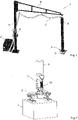
- a vacuum generator E With a tube lifter of this type, as exemplified in 1 is shown, a vacuum generator E, a pump or a blower depending on the application, is provided in order to generate a volume flow and to provide the required vacuum.
- the structure shown has a column D with a swivel arm B, on which the lifting tube A is suspended and connected to the vacuum generator E via a supply line C.
- the vacuum is achieved through a filter unit F, via the supply line C, a swivel joint, the lifting hose A and a control unit 3 in the form of a control head, a suction foot arrangement 2 or a suction foot, in order to suck up and transport the goods to be transported.
- the previously slack lifting tube A contracts.
- a spring is embedded in the lifting tube which, among other things, ensures that the lifting tube does not implode.
- the lifting force is greater than the weight of the goods to be transported, they are lifted.
- the vacuum in the overall system is raised or lowered.
- the lifting hose A consequently expands in length and the operating head with the suction foot and the transported goods are lowered.
- the vacuum increases, whereby the lifting hose is contracted in length with a correspondingly reduced inflow of external air and the operating head with the suction foot and the transported goods are lifted.
- the transported goods can be kept in suspension.
- the present invention is based on the object of providing a tube lifter of the type mentioned at the outset, with which the most precise possible transport function is achieved with the simplest possible operation.
- the closing element in connection with the features of the preamble, is held in the open position for the supply of external air by means of the force of the energy accumulator in the manually unactuated rest state, whereby the squeegee assembly assumes its lower position in the rest state.
- the closing element In the idle state of the control unit, which is when the control unit is not manually operated (and any locking is released), the closing element is held in its one end position, which represents the open position, by the force of the energy accumulator and the greatest possible inflow of external air (usually ambient air).
- the lifting tube expands to the maximum over its length and the suction foot arrangement is in its (geodetically) lower position, which means that when the actuating mechanism is released manually, the suction foot arrangement can be lifted, possibly with the load and any dangerous situation that may arise as a result is avoided.
- valve body is provided with a guide structure on which the closing element is guided so that it can be displaced in a translatory manner between the open position and the closed position in the axial direction.
- the operating function with smooth handling and an advantageous structure is favored by the fact that the vacuum chamber extends longitudinally through the housing body of the operating unit via a flow channel section from an upper connection side facing the lifting hose (A) to a lower connection side facing the suction foot arrangement and that the valve body is attached as a separate part or integrally formed on a wall surrounding the flow channel section, which is provided with at least one opening to the channel arrangement, protruding transversely to the longitudinal direction of the housing body with wall structures, with at least one passage opening of the channel arrangement for the external air in the wall structures are formed, and that the closing element is sleeve-shaped and surrounds the wall structures with the through-openings of the channel arrangement in the closed position in a sealing manner and in the open position or when partially open llation completely or partially releases the area of the duct arrangement for the supply of external air.
- the least a through-opening arranged in the lateral wall structures of the valve body, in cooperation with the closing element that can be displaced in the axial direction, allows the manual actuating device to move easily without abrupt changes in the manual actuating force and thus contributes significantly to simple operation and precisely controllable transport function.
- a further configuration that is advantageous for operation and the transport function is that the closing element has a circumferential sealing edge on its front end face facing the channel section, which in the closed position bears sealingly on a facing circumferential sealing surface of the valve body, in particular via an interposed sealing element, and in the full and the partial open position is spaced from this.
- the wall structures of the valve body in the axial direction have a first wall section lying close to the sealing surface, in which the at least one through opening is arranged, and an adjoining wall section further away in the axial direction lying from the sealing surface circumferential second wall section, the outer cross section of which is adapted to the inner cross section of the closing element in such a way that the closing element is slidably guided along the second wall section with sealing.
- valve function for regulating the external air volume flow and the operation are also advantageously supported by the fact that the outer cross section of the first wall section of the valve body is smaller over its axial extent than the inner cross section of the closing element, so that the first wall section with the at least one through opening arranged therein from the Inner surface of the closing element is spaced radially.
- valve body and the closing element have a cross section that is at least partially round, in particular circular, over their axial extension.
- Precise guidance of the closing element along the valve body is further assisted by the measures that the guiding structure of the valve body has, in its area remote from the flow channel section, guide elements that protrude like crenellations and pass through adapted guide openings in a rear cover wall area of the closing element that faces away from the flow channel section.
- the function and structure of the tube lifter with a compact design are also favored by the fact that the energy accumulator, which is based on a mechanical, electromotive, magnetic, pneumatic or hydraulic functional principle, is arranged inside the valve unit between the valve body and the closing element.
- the force accumulator in particular designed as a compression spring, is mounted between an abutment arranged in a stationary manner on the valve body and a support structure arranged in a stationary manner on the closing element, with its force effect being aligned in the axial direction (direction of displacement) that the closing element is held in the open position at rest.
- deflection element is mounted in the handle in a pivot bearing and is connected on the one hand via a coupling arm to be pivotable by means of a coupling bearing to the second lever arm of the button and on the other hand via an actuating arm to a rigid , Optionally adjustable, acting on the closing element mounted actuator to move the closing element.
- lever arm on the hand side or the deflection element, in particular on its coupling arm, is provided with an engagement structure, in particular in the form of toothing, also makes a significant contribution to the functional reliability of the operating unit, and that a locking mechanism is integrated in the handle, which when the handle is released with a Locking structure engages in the engagement structure to hold the closure member in the current position, and that the locking mechanism can be brought out of the locked state by manual operation.
- a locking mechanism is integrated in the handle, which when the handle is released with a Locking structure engages in the engagement structure to hold the closure member in the current position, and that the locking mechanism can be brought out of the locked state by manual operation.
- the locking mechanism has an unlocking button mounted in the handle, which is adjustable, in particular pivotable, in a locking bearing relative to the housing body and is provided with the locking structure adapted to the engagement structure, which is activated when the handle is released Handle lockingly engages the engagement structure to lock the closure member in the current position.
- the operating unit 3 is connected to the lifting hose A and the suction foot arrangement 2 in a vacuum-carrying manner and has a housing body and an attached,
- handle 30 can be grasped and operated with one hand, whereby the transported goods held by suction on the suction foot arrangement 2, which in the present case comprises two suction feet, are moved vertically together with the lower end of the lifting tube A and laterally (by means of the swivel arm ) can be moved to a desired location.
- the handle 30 is integrated into the operating unit 3 and has a curved outer surface on the outside, ergonomically adapted to the hand of the operator, against which the palm of the hand rests during handling, and has a free inner surface area facing away from the outside Penetration of the control unit 3 facing to grip the handle 30 with your fingers.
- a button 33 is arranged on the inner surface area (similar to a fuel nozzle), which can be pivoted in a pivot bearing 330 and moved inwards into the handle 30 against a spring force.
- an unlocking button 31 of a locking mechanism which is pivotably mounted in a locking bearing 310 via an actuating part which is arranged on the outside of the handle 30 and faces the palm of the hand during handling.
- a deflection element 32 is movably coupled to the button 33, which is arranged inside the handle 30 and is rotatably or pivotably mounted in a pivot bearing 320 and is articulated to the button 33 in a coupling bearing 322 on a coupling leg (cf. figure 5 ).
- An actuating leg of the deflection element 32 facing away from the coupling leg is designed to act on a closing element 41 of a valve unit 4 arranged in the operating unit 3 .
- the coupling leg of the deflection element 32 is provided with an engagement structure 321, which is adapted to an unlocking structure of the unlocking button 31 and interacts with it, wherein the engagement structure 321 and the locking structure can be brought into engagement with one another in a form-fitting manner, in particular via teeth, for locking.
- the pivot bearing 330 of the button 33, the pivot bearing 320 of the deflection element 32 and the locking bearing 310 of the unlocking button 31 each have a bearing element (such as a bearing pin or bearing eye) that is fixed in the housing body of the operating unit 3, for example a molded one.
- the valve unit 4 has a valve body 40 which is fixedly arranged in the housing body of the operating unit 3 and protrudes away from a wall 50 of a flow channel section 5 in the housing body of the operating unit 3 which leads from the interior of the lifting hose A to the suction foot arrangement 2.
- the valve body 40 has a guide structure 400 on which the closing element 41 is slidably guided to open and close the valve unit 4 in order to produce and regulate an external air supply via a channel arrangement to the flow channel section 5, with the regulation or setting of the external air supply being manual via the button 33 against the force of an energy accumulator 42, in this case designed as a compression spring.
- the valve unit 4 is held in the open position for the supply of external air by means of the energy accumulator 42 in the unactuated state and can be opened by pressing the button 33 against the force of the energy accumulator 42 by moving the closing element 41 to vary the external air volume flow up to its complete suppression closed position are moved. Conversely, when the button 33 is not actuated, the closing element 41 can be brought into the (completely) open position by means of the energy store 42 if the locking mechanism has been disengaged from the deflection element 32 by means of the unlocking button 31 .
- the unlocking button 31 engages with its locking structure in the engagement structure 321 of the deflection element 32 in order to lock the current position of the closing element 41 and to prevent the valve unit 4 from opening and the suction foot arrangement 2 with the load L being lowered rapidly as a result.
- the adjustment of the closing element 41 along the guide structure 400 of the valve body 40 takes place in a translatory or linear manner in the present embodiment of the valve unit 4 .
- the valve body 40 is overlapped by the closing element 41 designed as a sleeve, in particular a sleeve with a circular cross-section, the closing element 41 sealing in the closed position with a front, end-side circumferential sealing edge facing the wall 50 of the flow channel section 5 (possibly with the interposition of a sealing element). on a peripheral sealing surface of the valve body 40 rests.
- the valve body 40 has a first wall section 401 that is axially closer to the wall 50 or sealing surface 403, in which at least one through-opening of the channel arrangement for supplying the external air is introduced, as well as a circumferential second wall section 402 that is axially further away from the sealing surface 403. which is adapted in its external cross-section to the internal cross-section of the closing element 41 in such a way that it is guided along the second wall section 402 with as little play as possible, can be slid well and is sealingly guided.
- the first wall section 401 with the at least one through-opening is spaced radially inwards from the inside of the closing element 41 with respect to a central longitudinal axis (directed in the displacement direction) of the valve body 40, which facilitates the regulation of the state of external air with simple operation.
- the guide structure of the valve body 40 comprises, on its side facing away from the sealing surface 403, guide elements that protrude like crenels and protrude through a cover area of the closing element 41 that faces away from the sealing surface 403 in adapted openings, so that the closing element 41 is additionally guided during linear displacement.
- figure 5 shows the valve unit 4 in the open position, the front sealing edge of the closing element 41 being spaced apart from the sealing surface 403 and the at least one through-opening in the first wall section 401 being fully exposed (cf. also 4 the bold inflow arrows for external air), while 6 shows the valve unit 4 in its closed position, with the front, end-side sealing edge of the closing element 41 sealingly resting on the sealing surface 403.
- the energy accumulator 42 which moves the closing element 41 into the open position as a result of its force effect, is supported on the one hand (on its side facing the sealing surface 403) against an abutment which is fixed in the interior of the valve body, for example molded on, and on the other hand against an abutment which is fixed in the closing element 41 support structure, like that 4 , 5 and 6 reveal.
- the closing element 41 is provided on its side facing away from its sealing edge, in particular in the cover area, with an actuating projection directed in the opening direction (away from the flow channel section 5), with which the coupling leg of the deflection element 32 is brought into operative connection in order to move the closing element 41 when actuated (pressed in ) of the button 33 to move towards the closed position.
- An adjusting member in this case a cap nut, can be attached to the actuating pin of the closing element 41, by means of which the actuating force or the actuating travel can be suitably adjusted and a good sliding surface is provided.
- the actuating pin advantageously continues inside the closing element 41 in order to accommodate the energy accumulator 41 in the form of the compression spring, which is inserted in its section directed towards the sealing surface 403 into an adapted seat of the valve body 40, which facilitates the guiding of the closing element 41.
- the unlocking force on the unlocking button 31 using the palm of your hand on the outside of the handle 30 is preferably less than the actuating force on the button 33 for moving the closing element 41 against the force of the energy store 42 in the direction of the closed position.
- the unlocking is canceled in a simple manner when the button 33 is actuated, but when the handle 30 is released, its locking structure falls securely into the engagement structure 321 of the deflection element 32 in order to lock the closing element 41 in a current position and to maintain the external air volume flow set obtain.
- control unit is user-friendly and reliable.
Landscapes
- Engineering & Computer Science (AREA)
- Mechanical Engineering (AREA)
- Mechanically-Actuated Valves (AREA)
Applications Claiming Priority (1)
| Application Number | Priority Date | Filing Date | Title |
|---|---|---|---|
| DE102020128380.6A DE102020128380B4 (de) | 2020-10-28 | 2020-10-28 | Schlauchheber |
Publications (3)
| Publication Number | Publication Date |
|---|---|
| EP3992135A1 true EP3992135A1 (fr) | 2022-05-04 |
| EP3992135B1 EP3992135B1 (fr) | 2024-03-27 |
| EP3992135C0 EP3992135C0 (fr) | 2024-03-27 |
Family
ID=78332527
Family Applications (1)
| Application Number | Title | Priority Date | Filing Date |
|---|---|---|---|
| EP21203241.1A Active EP3992135B1 (fr) | 2020-10-28 | 2021-10-18 | Élévateur à bande souple |
Country Status (2)
| Country | Link |
|---|---|
| EP (1) | EP3992135B1 (fr) |
| DE (1) | DE102020128380B4 (fr) |
Families Citing this family (4)
| Publication number | Priority date | Publication date | Assignee | Title |
|---|---|---|---|---|
| DE102023102438B3 (de) * | 2023-02-01 | 2024-03-14 | J.Schmalz Gmbh | Bedienvorrichtung für einen Schlauchheber sowie Schlauchheber |
| DE102023117475B4 (de) * | 2023-07-03 | 2025-05-22 | J.Schmalz Gmbh | Schlauchheber mit Steuerventil |
| DE102024123584B3 (de) | 2024-08-19 | 2026-02-26 | J.Schmalz Gmbh | Schlauchheber mit Belüftungsventil |
| DE102024123588B3 (de) * | 2024-08-19 | 2026-01-22 | J.Schmalz Gmbh | Bedienvorrichtung für einen Schlauchheber sowie Schlauchheber |
Citations (6)
| Publication number | Priority date | Publication date | Assignee | Title |
|---|---|---|---|---|
| EP0509115B1 (fr) | 1990-03-29 | 1995-09-13 | Unitech Industries,Inc. | Système de commande de dépression pour moyens de levage |
| DE10038013A1 (de) | 2000-08-04 | 2002-02-21 | Fezer Maschf Albert | Steuergerät für eine Vakuum-Hebevorrichtung |
| DE10049149A1 (de) | 2000-10-04 | 2002-08-08 | Smi Handling Systeme Gmbh | Gerät zum Handhaben von Gegenständen mit Hilfskraft |
| DE102008028205C5 (de) | 2008-06-09 | 2015-03-05 | J. Schmalz Gmbh | Bedienvorrichtung |
| DE202018100403U1 (de) | 2018-01-24 | 2019-04-25 | J. Schmalz Gmbh | Bedienvorrichtung für einen Schlauchheber sowie Schlauchheber |
| EP3536650A1 (fr) | 2018-03-09 | 2019-09-11 | J. Schmalz GmbH | Dispositif de fonctionnement pour un siphon à tuyau et siphon à tuyau |
-
2020
- 2020-10-28 DE DE102020128380.6A patent/DE102020128380B4/de active Active
-
2021
- 2021-10-18 EP EP21203241.1A patent/EP3992135B1/fr active Active
Patent Citations (6)
| Publication number | Priority date | Publication date | Assignee | Title |
|---|---|---|---|---|
| EP0509115B1 (fr) | 1990-03-29 | 1995-09-13 | Unitech Industries,Inc. | Système de commande de dépression pour moyens de levage |
| DE10038013A1 (de) | 2000-08-04 | 2002-02-21 | Fezer Maschf Albert | Steuergerät für eine Vakuum-Hebevorrichtung |
| DE10049149A1 (de) | 2000-10-04 | 2002-08-08 | Smi Handling Systeme Gmbh | Gerät zum Handhaben von Gegenständen mit Hilfskraft |
| DE102008028205C5 (de) | 2008-06-09 | 2015-03-05 | J. Schmalz Gmbh | Bedienvorrichtung |
| DE202018100403U1 (de) | 2018-01-24 | 2019-04-25 | J. Schmalz Gmbh | Bedienvorrichtung für einen Schlauchheber sowie Schlauchheber |
| EP3536650A1 (fr) | 2018-03-09 | 2019-09-11 | J. Schmalz GmbH | Dispositif de fonctionnement pour un siphon à tuyau et siphon à tuyau |
Also Published As
| Publication number | Publication date |
|---|---|
| DE102020128380B4 (de) | 2023-01-05 |
| EP3992135B1 (fr) | 2024-03-27 |
| EP3992135C0 (fr) | 2024-03-27 |
| DE102020128380A1 (de) | 2022-04-28 |
Similar Documents
| Publication | Publication Date | Title |
|---|---|---|
| EP3992135B1 (fr) | Élévateur à bande souple | |
| EP3683389B1 (fr) | Mécanisme de réglage pour parties de meuble | |
| EP2767365B1 (fr) | Cloueur à air comprimé avec déclencheur manuel et capteur de contact | |
| EP0789157B1 (fr) | Ressort à gaz ajustable en longueur | |
| DE2513302A1 (de) | Blockierbare, pneumatische oder hydropneumatische feder | |
| EP3257633A1 (fr) | Cloueur a air comprime comprenant une chambre de commande de securite | |
| EP3536650B1 (fr) | Dispositif de fonctionnement pour un siphon à tuyau et siphon à tuyau | |
| DE10014063A1 (de) | Medizinischer oder dentalmedizinischer Behandlungsstuhl oder eine Kopfstütze für einen solchen Behandlungsstuhl | |
| EP3761936B1 (fr) | Brancard de sauvetage mobile | |
| DE102008047745A1 (de) | Höhenverstellbares Möbelstück | |
| DE102006022113A1 (de) | Flurförderzeug | |
| DE2619031B1 (de) | Laengenveraenderlicher oberlenker | |
| DE102015216557A1 (de) | Fensterheberbaugruppe für ein Kraftfahrzeug | |
| DE3924309A1 (de) | Gasdruckfeder | |
| DE10112344C1 (de) | Verdeckkastendeckel in einem Cabriolet-Fahrzeug | |
| DE4417027A1 (de) | Längenverstellbare Gasfeder | |
| DE202013001537U1 (de) | Druckluftnagler mit einem handbetätigbaren Auslöser und einem Aufsetzfühler | |
| EP0505349A2 (fr) | Vérin hydraulique | |
| DE3434247A1 (de) | Baueinheit zum anheben oder absenken eines an einen traktor angeschlossenen landwirtschaftlichen geraets | |
| EP4021785A1 (fr) | Tige de selle télescopique | |
| DE202015104588U1 (de) | Fensterheberbaugruppe für ein Kraftfahrzeug | |
| DE2614754A1 (de) | Pneumatischer wagenheber | |
| AT501605B1 (de) | Feststellvorrichtung zur fixierung der relativen lage von einem inneren rohrteil und einem äusseren rohrteil | |
| WO2009127186A1 (fr) | Cercleuse pneumatique à main | |
| DE10340725A1 (de) | Hubaggregat für Tische oder dergleichen |
Legal Events
| Date | Code | Title | Description |
|---|---|---|---|
| PUAI | Public reference made under article 153(3) epc to a published international application that has entered the european phase |
Free format text: ORIGINAL CODE: 0009012 |
|
| STAA | Information on the status of an ep patent application or granted ep patent |
Free format text: STATUS: THE APPLICATION HAS BEEN PUBLISHED |
|
| AK | Designated contracting states |
Kind code of ref document: A1 Designated state(s): AL AT BE BG CH CY CZ DE DK EE ES FI FR GB GR HR HU IE IS IT LI LT LU LV MC MK MT NL NO PL PT RO RS SE SI SK SM TR |
|
| STAA | Information on the status of an ep patent application or granted ep patent |
Free format text: STATUS: REQUEST FOR EXAMINATION WAS MADE |
|
| 17P | Request for examination filed |
Effective date: 20221104 |
|
| RBV | Designated contracting states (corrected) |
Designated state(s): AL AT BE BG CH CY CZ DE DK EE ES FI FR GB GR HR HU IE IS IT LI LT LU LV MC MK MT NL NO PL PT RO RS SE SI SK SM TR |
|
| GRAP | Despatch of communication of intention to grant a patent |
Free format text: ORIGINAL CODE: EPIDOSNIGR1 |
|
| STAA | Information on the status of an ep patent application or granted ep patent |
Free format text: STATUS: GRANT OF PATENT IS INTENDED |
|
| INTG | Intention to grant announced |
Effective date: 20231108 |
|
| GRAS | Grant fee paid |
Free format text: ORIGINAL CODE: EPIDOSNIGR3 |
|
| GRAA | (expected) grant |
Free format text: ORIGINAL CODE: 0009210 |
|
| STAA | Information on the status of an ep patent application or granted ep patent |
Free format text: STATUS: THE PATENT HAS BEEN GRANTED |
|
| AK | Designated contracting states |
Kind code of ref document: B1 Designated state(s): AL AT BE BG CH CY CZ DE DK EE ES FI FR GB GR HR HU IE IS IT LI LT LU LV MC MK MT NL NO PL PT RO RS SE SI SK SM TR |
|
| REG | Reference to a national code |
Ref country code: GB Ref legal event code: FG4D Free format text: NOT ENGLISH |
|
| REG | Reference to a national code |
Ref country code: CH Ref legal event code: EP |
|
| REG | Reference to a national code |
Ref country code: DE Ref legal event code: R096 Ref document number: 502021003095 Country of ref document: DE |
|
| REG | Reference to a national code |
Ref country code: IE Ref legal event code: FG4D Free format text: LANGUAGE OF EP DOCUMENT: GERMAN |
|
| U01 | Request for unitary effect filed |
Effective date: 20240426 |
|
| U07 | Unitary effect registered |
Designated state(s): AT BE BG DE DK EE FI FR IT LT LU LV MT NL PT SE SI Effective date: 20240503 |
|
| PG25 | Lapsed in a contracting state [announced via postgrant information from national office to epo] |
Ref country code: GR Free format text: LAPSE BECAUSE OF FAILURE TO SUBMIT A TRANSLATION OF THE DESCRIPTION OR TO PAY THE FEE WITHIN THE PRESCRIBED TIME-LIMIT Effective date: 20240628 |
|
| PG25 | Lapsed in a contracting state [announced via postgrant information from national office to epo] |
Ref country code: RS Free format text: LAPSE BECAUSE OF FAILURE TO SUBMIT A TRANSLATION OF THE DESCRIPTION OR TO PAY THE FEE WITHIN THE PRESCRIBED TIME-LIMIT Effective date: 20240627 Ref country code: HR Free format text: LAPSE BECAUSE OF FAILURE TO SUBMIT A TRANSLATION OF THE DESCRIPTION OR TO PAY THE FEE WITHIN THE PRESCRIBED TIME-LIMIT Effective date: 20240327 |
|
| PG25 | Lapsed in a contracting state [announced via postgrant information from national office to epo] |
Ref country code: RS Free format text: LAPSE BECAUSE OF FAILURE TO SUBMIT A TRANSLATION OF THE DESCRIPTION OR TO PAY THE FEE WITHIN THE PRESCRIBED TIME-LIMIT Effective date: 20240627 Ref country code: NO Free format text: LAPSE BECAUSE OF FAILURE TO SUBMIT A TRANSLATION OF THE DESCRIPTION OR TO PAY THE FEE WITHIN THE PRESCRIBED TIME-LIMIT Effective date: 20240627 Ref country code: HR Free format text: LAPSE BECAUSE OF FAILURE TO SUBMIT A TRANSLATION OF THE DESCRIPTION OR TO PAY THE FEE WITHIN THE PRESCRIBED TIME-LIMIT Effective date: 20240327 Ref country code: GR Free format text: LAPSE BECAUSE OF FAILURE TO SUBMIT A TRANSLATION OF THE DESCRIPTION OR TO PAY THE FEE WITHIN THE PRESCRIBED TIME-LIMIT Effective date: 20240628 |
|
| PG25 | Lapsed in a contracting state [announced via postgrant information from national office to epo] |
Ref country code: IS Free format text: LAPSE BECAUSE OF FAILURE TO SUBMIT A TRANSLATION OF THE DESCRIPTION OR TO PAY THE FEE WITHIN THE PRESCRIBED TIME-LIMIT Effective date: 20240727 |
|
| PG25 | Lapsed in a contracting state [announced via postgrant information from national office to epo] |
Ref country code: SM Free format text: LAPSE BECAUSE OF FAILURE TO SUBMIT A TRANSLATION OF THE DESCRIPTION OR TO PAY THE FEE WITHIN THE PRESCRIBED TIME-LIMIT Effective date: 20240327 |
|
| PG25 | Lapsed in a contracting state [announced via postgrant information from national office to epo] |
Ref country code: ES Free format text: LAPSE BECAUSE OF FAILURE TO SUBMIT A TRANSLATION OF THE DESCRIPTION OR TO PAY THE FEE WITHIN THE PRESCRIBED TIME-LIMIT Effective date: 20240327 |
|
| PG25 | Lapsed in a contracting state [announced via postgrant information from national office to epo] |
Ref country code: CZ Free format text: LAPSE BECAUSE OF FAILURE TO SUBMIT A TRANSLATION OF THE DESCRIPTION OR TO PAY THE FEE WITHIN THE PRESCRIBED TIME-LIMIT Effective date: 20240327 |
|
| PG25 | Lapsed in a contracting state [announced via postgrant information from national office to epo] |
Ref country code: PL Free format text: LAPSE BECAUSE OF FAILURE TO SUBMIT A TRANSLATION OF THE DESCRIPTION OR TO PAY THE FEE WITHIN THE PRESCRIBED TIME-LIMIT Effective date: 20240327 |
|
| PG25 | Lapsed in a contracting state [announced via postgrant information from national office to epo] |
Ref country code: SK Free format text: LAPSE BECAUSE OF FAILURE TO SUBMIT A TRANSLATION OF THE DESCRIPTION OR TO PAY THE FEE WITHIN THE PRESCRIBED TIME-LIMIT Effective date: 20240327 |
|
| PG25 | Lapsed in a contracting state [announced via postgrant information from national office to epo] |
Ref country code: SM Free format text: LAPSE BECAUSE OF FAILURE TO SUBMIT A TRANSLATION OF THE DESCRIPTION OR TO PAY THE FEE WITHIN THE PRESCRIBED TIME-LIMIT Effective date: 20240327 Ref country code: SK Free format text: LAPSE BECAUSE OF FAILURE TO SUBMIT A TRANSLATION OF THE DESCRIPTION OR TO PAY THE FEE WITHIN THE PRESCRIBED TIME-LIMIT Effective date: 20240327 Ref country code: RO Free format text: LAPSE BECAUSE OF FAILURE TO SUBMIT A TRANSLATION OF THE DESCRIPTION OR TO PAY THE FEE WITHIN THE PRESCRIBED TIME-LIMIT Effective date: 20240327 Ref country code: PL Free format text: LAPSE BECAUSE OF FAILURE TO SUBMIT A TRANSLATION OF THE DESCRIPTION OR TO PAY THE FEE WITHIN THE PRESCRIBED TIME-LIMIT Effective date: 20240327 Ref country code: IS Free format text: LAPSE BECAUSE OF FAILURE TO SUBMIT A TRANSLATION OF THE DESCRIPTION OR TO PAY THE FEE WITHIN THE PRESCRIBED TIME-LIMIT Effective date: 20240727 Ref country code: ES Free format text: LAPSE BECAUSE OF FAILURE TO SUBMIT A TRANSLATION OF THE DESCRIPTION OR TO PAY THE FEE WITHIN THE PRESCRIBED TIME-LIMIT Effective date: 20240327 Ref country code: CZ Free format text: LAPSE BECAUSE OF FAILURE TO SUBMIT A TRANSLATION OF THE DESCRIPTION OR TO PAY THE FEE WITHIN THE PRESCRIBED TIME-LIMIT Effective date: 20240327 |
|
| U20 | Renewal fee for the european patent with unitary effect paid |
Year of fee payment: 4 Effective date: 20241025 |
|
| REG | Reference to a national code |
Ref country code: DE Ref legal event code: R097 Ref document number: 502021003095 Country of ref document: DE |
|
| PLBE | No opposition filed within time limit |
Free format text: ORIGINAL CODE: 0009261 |
|
| STAA | Information on the status of an ep patent application or granted ep patent |
Free format text: STATUS: NO OPPOSITION FILED WITHIN TIME LIMIT |
|
| 26N | No opposition filed |
Effective date: 20250103 |
|
| REG | Reference to a national code |
Ref country code: CH Ref legal event code: PL |
|
| PG25 | Lapsed in a contracting state [announced via postgrant information from national office to epo] |
Ref country code: MC Free format text: LAPSE BECAUSE OF FAILURE TO SUBMIT A TRANSLATION OF THE DESCRIPTION OR TO PAY THE FEE WITHIN THE PRESCRIBED TIME-LIMIT Effective date: 20240327 |
|
| PG25 | Lapsed in a contracting state [announced via postgrant information from national office to epo] |
Ref country code: CH Free format text: LAPSE BECAUSE OF NON-PAYMENT OF DUE FEES Effective date: 20241031 |
|
| PG25 | Lapsed in a contracting state [announced via postgrant information from national office to epo] |
Ref country code: IE Free format text: LAPSE BECAUSE OF NON-PAYMENT OF DUE FEES Effective date: 20241018 |
|
| U20 | Renewal fee for the european patent with unitary effect paid |
Year of fee payment: 5 Effective date: 20251031 |
|
| PG25 | Lapsed in a contracting state [announced via postgrant information from national office to epo] |
Ref country code: CY Free format text: LAPSE BECAUSE OF FAILURE TO SUBMIT A TRANSLATION OF THE DESCRIPTION OR TO PAY THE FEE WITHIN THE PRESCRIBED TIME-LIMIT; INVALID AB INITIO Effective date: 20211018 |
|
| PG25 | Lapsed in a contracting state [announced via postgrant information from national office to epo] |
Ref country code: HU Free format text: LAPSE BECAUSE OF FAILURE TO SUBMIT A TRANSLATION OF THE DESCRIPTION OR TO PAY THE FEE WITHIN THE PRESCRIBED TIME-LIMIT; INVALID AB INITIO Effective date: 20211018 |