EP3992154A1 - Flüssigkeitssterilisationsvorrichtung - Google Patents
Flüssigkeitssterilisationsvorrichtung Download PDFInfo
- Publication number
- EP3992154A1 EP3992154A1 EP21190782.9A EP21190782A EP3992154A1 EP 3992154 A1 EP3992154 A1 EP 3992154A1 EP 21190782 A EP21190782 A EP 21190782A EP 3992154 A1 EP3992154 A1 EP 3992154A1
- Authority
- EP
- European Patent Office
- Prior art keywords
- tubular portion
- discharge head
- light
- fluid
- window
- Prior art date
- Legal status (The legal status is an assumption and is not a legal conclusion. Google has not performed a legal analysis and makes no representation as to the accuracy of the status listed.)
- Granted
Links
Images
Classifications
-
- C—CHEMISTRY; METALLURGY
- C02—TREATMENT OF WATER, WASTE WATER, SEWAGE, OR SLUDGE
- C02F—TREATMENT OF WATER, WASTE WATER, SEWAGE, OR SLUDGE
- C02F1/00—Treatment of water, waste water, or sewage
- C02F1/30—Treatment of water, waste water, or sewage by irradiation
- C02F1/32—Treatment of water, waste water, or sewage by irradiation with ultraviolet light
- C02F1/325—Irradiation devices or lamp constructions
-
- C—CHEMISTRY; METALLURGY
- C02—TREATMENT OF WATER, WASTE WATER, SEWAGE, OR SLUDGE
- C02F—TREATMENT OF WATER, WASTE WATER, SEWAGE, OR SLUDGE
- C02F2101/00—Nature of the contaminant
- C02F2101/10—Inorganic compounds
-
- C—CHEMISTRY; METALLURGY
- C02—TREATMENT OF WATER, WASTE WATER, SEWAGE, OR SLUDGE
- C02F—TREATMENT OF WATER, WASTE WATER, SEWAGE, OR SLUDGE
- C02F2103/00—Nature of the water, waste water, sewage or sludge to be treated
- C02F2103/06—Contaminated groundwater or leachate
-
- C—CHEMISTRY; METALLURGY
- C02—TREATMENT OF WATER, WASTE WATER, SEWAGE, OR SLUDGE
- C02F—TREATMENT OF WATER, WASTE WATER, SEWAGE, OR SLUDGE
- C02F2103/00—Nature of the water, waste water, sewage or sludge to be treated
- C02F2103/08—Seawater, e.g. for desalination
-
- C—CHEMISTRY; METALLURGY
- C02—TREATMENT OF WATER, WASTE WATER, SEWAGE, OR SLUDGE
- C02F—TREATMENT OF WATER, WASTE WATER, SEWAGE, OR SLUDGE
- C02F2201/00—Apparatus for treatment of water, waste water or sewage
- C02F2201/32—Details relating to UV-irradiation devices
- C02F2201/322—Lamp arrangement
- C02F2201/3222—Units using UV-light emitting diodes [LED]
-
- C—CHEMISTRY; METALLURGY
- C02—TREATMENT OF WATER, WASTE WATER, SEWAGE, OR SLUDGE
- C02F—TREATMENT OF WATER, WASTE WATER, SEWAGE, OR SLUDGE
- C02F2201/00—Apparatus for treatment of water, waste water or sewage
- C02F2201/32—Details relating to UV-irradiation devices
- C02F2201/322—Lamp arrangement
- C02F2201/3223—Single elongated lamp located on the central axis of a turbular reactor
-
- C—CHEMISTRY; METALLURGY
- C02—TREATMENT OF WATER, WASTE WATER, SEWAGE, OR SLUDGE
- C02F—TREATMENT OF WATER, WASTE WATER, SEWAGE, OR SLUDGE
- C02F2201/00—Apparatus for treatment of water, waste water or sewage
- C02F2201/32—Details relating to UV-irradiation devices
- C02F2201/322—Lamp arrangement
- C02F2201/3228—Units having reflectors, e.g. coatings, baffles, plates, mirrors
-
- C—CHEMISTRY; METALLURGY
- C02—TREATMENT OF WATER, WASTE WATER, SEWAGE, OR SLUDGE
- C02F—TREATMENT OF WATER, WASTE WATER, SEWAGE, OR SLUDGE
- C02F2201/00—Apparatus for treatment of water, waste water or sewage
- C02F2201/32—Details relating to UV-irradiation devices
- C02F2201/324—Lamp cleaning installations, e.g. brushes
-
- C—CHEMISTRY; METALLURGY
- C02—TREATMENT OF WATER, WASTE WATER, SEWAGE, OR SLUDGE
- C02F—TREATMENT OF WATER, WASTE WATER, SEWAGE, OR SLUDGE
- C02F2303/00—Specific treatment goals
- C02F2303/04—Disinfection
-
- C—CHEMISTRY; METALLURGY
- C02—TREATMENT OF WATER, WASTE WATER, SEWAGE, OR SLUDGE
- C02F—TREATMENT OF WATER, WASTE WATER, SEWAGE, OR SLUDGE
- C02F2303/00—Specific treatment goals
- C02F2303/08—Corrosion inhibition
-
- C—CHEMISTRY; METALLURGY
- C02—TREATMENT OF WATER, WASTE WATER, SEWAGE, OR SLUDGE
- C02F—TREATMENT OF WATER, WASTE WATER, SEWAGE, OR SLUDGE
- C02F2303/00—Specific treatment goals
- C02F2303/14—Maintenance of water treatment installations
-
- C—CHEMISTRY; METALLURGY
- C02—TREATMENT OF WATER, WASTE WATER, SEWAGE, OR SLUDGE
- C02F—TREATMENT OF WATER, WASTE WATER, SEWAGE, OR SLUDGE
- C02F2303/00—Specific treatment goals
- C02F2303/22—Eliminating or preventing deposits, scale removal, scale prevention
Definitions
- Embodiments described herein relate to a fluid sterilization device.
- a fluid sterilization device that irradiates a fluid such as water with ultraviolet rays to sterilize the fluid.
- a fluid sterilization device which includes a tubular portion through which a fluid flows and a light source that is provided in an end portion of the tubular portion and irradiates the inside of the tubular portion with ultraviolet rays.
- the fluid flowing through the inside of the tubular portion is directly irradiated with a part of the ultraviolet rays emitted from the light source.
- the ultraviolet rays emitted from the light source and incident on an inner surface of the tubular portion propagate while being repeatedly reflected inside the tubular portion.
- Such a fluid sterilization device can also be used for sterilizing, for example, seawater, groundwater, or the like.
- seawater, groundwater, or the like contains a foreign substance such as sand, dead microorganisms, or inorganic salts.
- a foreign substance may adhere to a wetted portion of the fluid sterilization device, so that the sterilization effect is reduced.
- the reflectivity decreases.
- the intensity of reflected light (ultraviolet rays) with which the fluid is irradiated also decreases, so that the sterilization effect is reduced.
- a part of the ultraviolet rays emitted from the light source toward the fluid is blocked, so that the sterilization effect is reduced.
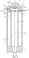
- FIG. 1 is a schematic cross-sectional view illustrating a fluid sterilization device according to the embodiment.
- a fluid sterilization device includes a tubular portion; a supply head provided in one end portion of the tubular portion; a discharge head provided in the other end portion of the tubular portion, and including a hole penetrating through the discharge head between an end face on a tubular portion side and an end face on a side opposite the tubular portion side; a substrate provided inside the hole of the discharge head; a light-emitting element provided on a surface on the tubular portion side of the substrate, and configured to emit an ultraviolet ray; and a window provided in the discharge head, and facing the light-emitting element.
- a surface roughness Ra of an inner surface of the tubular portion is 50 nanometers (nm) or less.
- FIG. 1 is a schematic cross-sectional view illustrating a fluid sterilization device 1 according to the embodiment.
- the fluid sterilization device 1 includes, for example, a tubular portion 2, a cover 3, a supply head 4, a discharge head 5, a light source 6, a window 7, a cooling unit 8, and a scraper 9.
- the tubular portion 2 has a cylindrical shape, and end portions on both sides are open.
- the tubular portion 2 can be, for example, a cylindrical tube.
- Ultraviolet rays are emitted from the light source 6 to the inside of the tubular portion 2, and when a part of the emitted ultraviolet rays is transmitted through the tubular portion 2 to leak to the outside, the treatment capacity of the fluid sterilization device 1 decreases. For this reason, it is desirable that the tubular portion 2 is made of a material that does not transmit ultraviolet rays and has a high reflectivity to ultraviolet rays.
- the tubular portion 2 can be made of a metal having a high reflectivity to ultraviolet rays.
- the utilization efficiency of ultraviolet rays emitted from the light source 6 can be improved.
- the number of light-emitting elements 61 can be reduced.
- the size reduction, the cost reduction, the energy saving, and the like of the light source 6 can be achieved.
- an internal space of the tubular portion 2 serves as a flow path of the fluid 301a to be sterilized.
- the fluid 301a comes into contact with the inner surface of the tubular portion 2.
- the fluid 301a may be seawater, groundwater, or the like.
- seawater comes into contact with the inner surface of the tubular portion 2 of which the material contains a metal, corrosion may occur.
- the tubular portion 2 is made of a metal having corrosion resistance to a liquid such as seawater which easily causes corrosion.
- the tubular portion 2 is made of stainless steel containing 8 wt% or more of nickel (Ni), the reflectivity to ultraviolet rays and corrosion resistance to a liquid such as seawater which easily causes corrosion can be improved.
- Ni nickel
- SUS 304, SUS 316, or the like can be used as the stainless steel.
- seawater, groundwater, or the like contains a foreign substance such as sand, dead microorganisms, or inorganic salts. Since the fluid 301a comes into contact with the inner surface of the tubular portion 2, when the fluid 301a contains a foreign substance, the foreign substance is likely to adhere to the inner surface of the tubular portion 2. When a foreign substance adheres to the inner surface of the tubular portion 2, the reflectivity to ultraviolet rays may decrease. When the reflectivity decreases, the intensity of reflected light (ultraviolet rays) with which the fluid 301a is irradiated decreases, so that the sterilization effect is reduced, which is a problem.
- a foreign substance such as sand, dead microorganisms, or inorganic salts.
- the surface roughness (arithmetic average roughness) Ra of the inner surface of the tubular portion 2 is in a range of 50 nanometers (nm) or less and preferably in a range of 3 nanometers (nm) to 50 nanometers (nm)
- the adhesion of a foreign substance to the inner surface of the tubular portion 2 can be suppressed, and the reflectivity to ultraviolet rays can be improved.
- the surface roughness Ra of the inner surface of the tubular portion 2 can be placed in the above numerical range by buffing the inner surface of the tubular portion 2.
- the cover 3 has a cylindrical shape, and end portions on both sides are open.
- the cover 3 can be, for example, a cylindrical tube.
- the tubular portion 2 is stored in the internal space of the cover 3.
- the material of the cover 3 is not particularly limited as long as the material has a certain degree of rigidity.
- the material of the cover 3 can be, for example, a metal such as stainless steel.
- the cover 3 can be fixed to the supply head 4 and the discharge head 5.
- a method for fixing the cover 3 is not particularly limited.
- one end portion of the cover 3 can be provided inside a recessed portion or groove provided in the supply head 4, and the other end portion of the cover 3 can be provided inside a recessed portion or groove provided in the discharge head 5.
- the end portions on both sides of the cover 3 may be provided with respective flanges.
- One flange may be fixed to the supply head 4 with screws or the like, and the other flange may be fixed to the discharge head 5 with screws or the like.
- the cover 3 is not always required, and can also be omitted. Meanwhile, when the cover 3 is provided, an external force can be suppressed from being directly applied to the tubular portion 2.
- the supply head 4 is provided in one end portion of the tubular portion 2.
- a seal member not illustrated can be provided between the supply head 4 and the end portion of the tubular portion 2.
- the seal member provides liquid-tight sealing between the supply head 4 and the tubular portion 2.
- the seal member can be, for example, an O-ring or the like.
- the supply head 4 has, for example, a columnar shape, and includes a hole 4a penetrating through the supply head 4 between an end face on a tubular portion 2 side and an end face on a side opposite the tubular portion 2 side.
- An opening on the tubular portion 2 side of the hole 4a is connected to the internal space of the tubular portion 2.
- An opening on an opposite side of the hole 4a to the tubular portion 2 side serves as a supply port 4al.
- a supply source of the fluid 301a can be connected to the supply port 4a1 via a pipe.
- a filter, a straightening plate, or the like can be provided inside the hole 4a.
- the material of the supply head 4 is not particularly limited as long as the material has resistance to the fluid 301a and ultraviolet rays.
- the material of the supply head 4 can be, for example, a metal such as stainless steel.
- the supply head 4 is made of stainless steel containing 8 wt% or more of Ni. Thereby, even when seawater or the like is sterilized, corrosion can be suppressed from occurring in the supply head 4.
- the discharge head 5 is provided in the other end portion of the tubular portion 2.
- a seal member not illustrated can be provided between the discharge head 5 and the end portion of the tubular portion 2.
- the seal member provides liquid-tight sealing between the discharge head 5 and the tubular portion 2.
- the seal member can be, for example, an O-ring or the like.
- the discharge head 5 has, for example, a columnar shape, and includes a hole 5a and a hole 5b.
- An opening on the tubular portion 2 side of the hole 5a is connected to the internal space of the tubular portion 2.
- An opening on an opposite side of the hole 5a to the tubular portion 2 side serves as a discharge port 5a1 provided in a side surface of the discharge head 5.
- a sterilized fluid 301b is discharged from the discharge port 5a1.
- a tank or the like that stores the sterilized fluid 301b can be connected to the discharge port 5a1 via a pipe.
- the hole 5a is a bent flow path.
- the hole 5a includes a flow path 5a2 substantially parallel to an end face on the tubular portion 2 side of the discharge head 5, and a flow path 5a3 extending in an axial direction of the discharge head 5.
- the flow path 5a2 is open to the end face on the tubular portion 2 side of the discharge head 5.
- the window 7 is exposed to an inner wall of the flow path 5a2.
- the flow path 5a2 is, for example, a disk-shaped space.
- One end portion of the flow path 5a3 is connected to the vicinity of a peripheral edge of the flow path 5a2.
- the discharge port 5a1 is connected to the other end portion of the flow path 5a3.
- the flow path 5a3 is, for example, a cylindrical space.
- Ultraviolet rays emitted from the light source 6 are incident on the flow path 5a2 via the window 7. For this reason, the fluid 301a flowing through the flow path 5a2 is sterilized by the ultraviolet rays.
- the internal space of the tubular portion 2 is irradiated with a part of the ultraviolet rays incident on the flow path 5a2. A part of the ultraviolet rays with which the internal space of the tubular portion 2 is irradiated is reflected on the inner surface of the tubular portion 2. For this reason, the fluid 301a flowing through the inside of the tubular portion 2 is sterilized by the ultraviolet rays.
- the hole 5b is open to the end face on the opposite side of the discharge head 5 to the tubular portion 2 side, and the flow path 5a2.
- the discharge head 5 includes the holes (the hole 5b and the hole 5a) penetrating through the discharge head 5 between the end face on the tubular portion 2 side and the end face opposite the tubular portion 2 side.
- a protrusion portion 63b of a holder 63, a substrate 62, and the light-emitting element 61 are provided in the hole 5b.
- the material of the discharge head 5 is not particularly limited as long as the material has resistance to the fluids 301a and 301b and ultraviolet rays.
- the material of the discharge head 5 can be, for example, a metal such as stainless steel.
- the discharge head 5 is made of stainless steel containing 8 wt% or more of Ni. Thereby, even when seawater or the like is sterilized, corrosion can be suppressed from occurring in the discharge head 5.
- the light source 6 is detachably provided in the discharge head 5.
- the light source 6 includes, for example, the light-emitting element 61, the substrate 62, and the holder 63.
- the light-emitting element 61 is provided on a surface on the tubular portion 2 side of the substrate 62.
- the light-emitting element 61 emits ultraviolet rays toward the window 7.
- At least one light-emitting element 61 can be provided.
- the plurality of light-emitting elements 61 can be connected in series to each other.
- the light-emitting element 61 is not particularly limited as long as the light-emitting element 61 is an element that generates ultraviolet rays.
- the light-emitting element 61 can be, for example, a light-emitting diode, a laser diode, or the like.
- the peak wavelength of ultraviolet rays emitted from the light-emitting element 61 is not particularly limited as long as the peak wavelength has a sterilization effect. Meanwhile, when the peak wavelength is from 255 nm to 290 nm, the sterilization effect can be improved. For this reason, it is preferable that the light-emitting element 61 is capable of emitting ultraviolet rays of a peak wavelength of 255 nm to 290 nm.
- the substrate 62 has a plate shape, and is provided on an end face on the tubular portion 2 side of the protrusion portion 63b.
- the substrate 62 can be provided with a wiring pattern. It is preferable that the material of the substrate 62 has resistance to ultraviolet rays.
- the material of the substrate 62 can be, for example, ceramics such as aluminum oxide.
- the substrate 62 can be a metal plate of which the surface is covered with an inorganic material (metal core substrate). When the material of the substrate 62 is ceramics or the like or the substrate 62 is a metal core substrate, resistance to ultraviolet rays and high thermal radiation can be obtained.
- the holder 63 can be detachably provided in the discharge head 5.
- the light-emitting element 61 has a lifespan longer than that of a discharge lamp or the like, but when the lighting time is lengthened, the light-emitting efficiency decreases. In addition, it can be considered that the light-emitting element 61 cannot be lighted up due to a failure. When the holder 63 is detachably provided in the discharge head 5, the light-emitting element 61 can be easily replaced.
- the holder 63 includes, for example, a flange 63a and the protrusion portion 63b.
- the flange 63a and the protrusion portion 63b can be integrally formed.
- the flange 63a has a plate shape, and is provided on the end face on the opposite side of the discharge head 5 to the tubular portion 2 side.
- the flange 63a is attached to the discharge head 5 using, for example, a fastening member such as screws.
- the protrusion portion 63b is provided in a surface on the tubular portion 2 side of the flange 63a.
- the protrusion portion 63b protrudes from one surface of the flange 63a, and is provided inside the hole 5b of the discharge head 5.
- the substrate 62 on which the light-emitting element 61 is mounted can be provided on the end face on the tubular portion 2 side of the protrusion portion 63b.
- the protrusion portion 63b can have a function of determining the position of the light-emitting element 61 with respect to the discharge head 5. For example, a side surface of the protrusion portion 63b can be in contact with an inner wall of the hole 5b of the discharge head 5. In this manner, the position of the light-emitting element 61 with respect to the discharge head 5 can be determined.
- the discharge head 5 since the hole 5b and the flow path 5a2 of the discharge head 5 are partitioned off from each other by the window 7, even in a state where the fluid 301a is present in the flow path 5a2, the discharge head 5 (light source 6) can be attached and detached. For this reason, maintainability can be improved.
- the holder 63 has a function of releasing heat, which is generated in the light-emitting element 61, to the outside. For this reason, it is preferable that the holder 63 is made of a material having a high thermal conductivity.
- the holder 63 can be made of, for example, a metal such as aluminum, copper, or stainless steel.
- thermal radiation fins can also be provided in an end face on a side opposite the tubular portion 2 side, a side surface, or the like of the holder 63.
- the window 7 has a plate shape, and is liquid-tightly provided in the inner wall of the hole 5b of the discharge head 5. Namely, the window 7 is provided in the discharge head 5, and one surface of the window 7 is exposed to the flow path 5a2 provided in the discharge head 5.
- the planar shape of the window 7 can be, for example, a quadrilateral shape. When the planar shape of the window 7 is a quadrilateral shape, the scraper 9 can easily come into contact with the entire surface of the window 7. For this reason, the foreign substance adhering to the window 7 is easily removed.
- the window 7 faces the light-emitting element 61.
- a space 5b1 can be provided between the window 7 and the light-emitting element 61.
- the window 7 can transmit ultraviolet rays, and is made of a material having resistance to ultraviolet rays and the fluid 301a.
- the window 7 is made of, for example, quartz or a fluororesin transmitting ultraviolet rays, or the like.
- an antireflection film can also be provided on a surface on a light-emitting element 61 side of the window 7.
- the antireflection film is provided, ultraviolet rays emitted from the light-emitting element 61 can be suppressed from being reflected by the window 7, thereby facilitating the irradiation of the fluid 301a. Namely, the utilization efficiency of the ultraviolet rays emitted from the light-emitting element 61 can be improved.
- an antifouling film can also be provided on a surface on the tubular portion 2 side of the window 7.
- the fluid 301a may contain a foreign substance.
- the transmission of ultraviolet rays through the window 7 is difficult, the ultraviolet rays being emitted from the light-emitting element 61.
- the antifouling film is provided, the adhesion of a foreign substance to the window 7 can be suppressed.
- the cooling unit 8 can be provided, for example, on an opposite side of the holder 63 to the light-emitting element 61 side.
- the cooling unit 8 can be, for example, a fan that supplies air to the holder 63.
- the cooling unit 8 can be a fan that supplies air to the thermal radiation fins.
- the cooling unit 8 may supply a liquid to a flow path provided in the holder 63.
- the cooling unit 8 may be an air cooling type or a liquid cooling type.
- the cooling unit 8 can also be omitted depending on the number or heat quantity of the light-emitting elements 61 and the temperature, flow rate, or the like of the fluid 301a. Meanwhile, when the cooling unit 8 is provided, even when the number, applied electric power, or the like of the light-emitting elements 61 is increased, the temperature of the light-emitting element 61 is unlikely to exceed the maximum junction temperature.
- the cooling unit 8 when the cooling unit 8 is provided, even when the temperature of the fluid 301a increases or the flow rate of the fluid 301a of a high temperature increases, the temperature of the light-emitting element 61 is unlikely to exceed the maximum junction temperature. For this reason, the range of the fluid 301a, which can be handled, can be expanded.
- the fluid 301a comes into contact with the surface on the tubular portion 2 side of the window 7, when the fluid 301a contains a foreign substance, the foreign substance is likely to adhere to the surface on the tubular portion 2 side of the window 7.
- ultraviolet rays emitted from the light source 6 are unlikely to be incident on the flow path 5a2. For this reason, the sterilization effect is reduced, which is a problem.
- the antifouling film when the antifouling film is provided on the surface on the tubular portion 2 side of the window 7, the adhesion of a foreign substance can be suppressed.
- the antifouling film when the amount of a foreign substance contained in the fluid 301a is large, suppressing the adhesion of the foreign substance may be difficult.
- the fluid sterilization device 1 is provided with the scraper 9 that removes the foreign substance adhering to the window 7.
- the scraper 9 can be provided in the discharge head 5.
- a seal member 10 can be provided between the scraper 9 and the discharge head 5.
- the seal member 10 provides liquid-tight sealing between the scraper 9 and the discharge head 5.
- the scraper 9 is movable along the surface of the window 7 in a state where the scraper 9 is in contact with the surface on the tubular portion 2 side of the window 7.
- one end portion 9a of the scraper 9 can be in contact with the surface on the tubular portion 2 side of the window 7.
- the other end portion 9b of the scraper 9 can be exposed from the discharge head 5.
- the scraper 9 is movable in a direction orthogonal to a central axis of the tubular portion 2.
- the scraper 9 is capable of scraping a foreign substance adhering to the window 7.
- the movement of the scraper 9 may be performed by a worker or may be performed by using a drive device such as a motor or an air cylinder.
- a drive device such as a motor or an air cylinder.
- the removal of a foreign substance by the scraper 9 can be performed according to the amount of the adhering foreign substance, or can be performed periodically.
- the material of the scraper 9 is not particularly limited as long as the material has resistance to the fluid 301a and ultraviolet rays.
- the material of the scraper 9 can be, for example, a metal such as stainless steel.
- the scraper 9 is made of stainless steel containing 8 wt% or more of Ni. Thereby, even when seawater or the like is sterilized, corrosion can be suppressed from occurring in the scraper 9.
Landscapes
- Health & Medical Sciences (AREA)
- Toxicology (AREA)
- Life Sciences & Earth Sciences (AREA)
- Hydrology & Water Resources (AREA)
- Engineering & Computer Science (AREA)
- Environmental & Geological Engineering (AREA)
- Water Supply & Treatment (AREA)
- Chemical & Material Sciences (AREA)
- Organic Chemistry (AREA)
- Physical Water Treatments (AREA)
- Apparatus For Disinfection Or Sterilisation (AREA)
Applications Claiming Priority (2)
| Application Number | Priority Date | Filing Date | Title |
|---|---|---|---|
| JP2020181521 | 2020-10-29 | ||
| JP2021107248A JP7632120B2 (ja) | 2020-10-29 | 2021-06-29 | 流体殺菌装置 |
Publications (2)
| Publication Number | Publication Date |
|---|---|
| EP3992154A1 true EP3992154A1 (de) | 2022-05-04 |
| EP3992154B1 EP3992154B1 (de) | 2024-10-30 |
Family
ID=77300822
Family Applications (1)
| Application Number | Title | Priority Date | Filing Date |
|---|---|---|---|
| EP21190782.9A Active EP3992154B1 (de) | 2020-10-29 | 2021-08-11 | Flüssigkeitssterilisationsvorrichtung |
Country Status (3)
| Country | Link |
|---|---|
| US (1) | US20220135440A1 (de) |
| EP (1) | EP3992154B1 (de) |
| CN (1) | CN215886449U (de) |
Citations (4)
| Publication number | Priority date | Publication date | Assignee | Title |
|---|---|---|---|---|
| US20120235059A1 (en) * | 2011-03-17 | 2012-09-20 | Kabushiki Kaisha Toshiba | Ultraviolet irradiation apparatus |
| KR20170116549A (ko) * | 2016-04-11 | 2017-10-19 | 유태경 | Uv led를 이용하는 녹조 제거 장치 |
| CN210117304U (zh) * | 2018-12-19 | 2020-02-28 | 南通海发水处理工程有限公司 | 一种净水除菌过滤装置 |
| JP2020157187A (ja) * | 2019-03-25 | 2020-10-01 | 東芝ライテック株式会社 | 流体殺菌装置 |
Family Cites Families (3)
| Publication number | Priority date | Publication date | Assignee | Title |
|---|---|---|---|---|
| US6692694B1 (en) * | 1998-11-09 | 2004-02-17 | Clean Earth Technologies, Llc | Method and apparatus for photosensitized ultraviolet decontamination of surfaces and aerosol clouds |
| FR2835517B1 (fr) * | 2002-02-04 | 2005-02-25 | Jean Luc Renaud | Nouveau dispositif generateur d'ozone |
| JP2018019670A (ja) * | 2016-08-05 | 2018-02-08 | 株式会社トクヤマ | 液体の殺菌方法及び殺菌装置 |
-
2021
- 2021-08-11 EP EP21190782.9A patent/EP3992154B1/de active Active
- 2021-08-12 US US17/400,962 patent/US20220135440A1/en not_active Abandoned
- 2021-08-16 CN CN202121930212.1U patent/CN215886449U/zh active Active
Patent Citations (4)
| Publication number | Priority date | Publication date | Assignee | Title |
|---|---|---|---|---|
| US20120235059A1 (en) * | 2011-03-17 | 2012-09-20 | Kabushiki Kaisha Toshiba | Ultraviolet irradiation apparatus |
| KR20170116549A (ko) * | 2016-04-11 | 2017-10-19 | 유태경 | Uv led를 이용하는 녹조 제거 장치 |
| CN210117304U (zh) * | 2018-12-19 | 2020-02-28 | 南通海发水处理工程有限公司 | 一种净水除菌过滤装置 |
| JP2020157187A (ja) * | 2019-03-25 | 2020-10-01 | 東芝ライテック株式会社 | 流体殺菌装置 |
Also Published As
| Publication number | Publication date |
|---|---|
| US20220135440A1 (en) | 2022-05-05 |
| CN215886449U (zh) | 2022-02-22 |
| EP3992154B1 (de) | 2024-10-30 |
Similar Documents
| Publication | Publication Date | Title |
|---|---|---|
| EP3974002B1 (de) | Flüssigkeitssterilisationsvorrichtung | |
| JP7230624B2 (ja) | 流体殺菌装置 | |
| CN211797808U (zh) | 用于为穿流的流体消毒的装置 | |
| EP4052731A1 (de) | Flüssigkeitssterilisationsvorrichtung | |
| JP2011522697A (ja) | 光化学反応装置、及び光化学プロセスシステム | |
| CN107208988A (zh) | 用于借助表层水冷却流体的冷却装置 | |
| EP3992154B1 (de) | Flüssigkeitssterilisationsvorrichtung | |
| CN217650942U (zh) | 流体杀菌装置 | |
| JP2020103629A (ja) | 流体殺菌装置 | |
| JP2022073930A (ja) | 流体殺菌装置 | |
| TW202513099A (zh) | 流體殺菌裝置 | |
| US11957802B2 (en) | Fluid sterilization apparatus and fluid sterilization system | |
| CN220520209U (zh) | 流体处理装置 | |
| JP7445191B2 (ja) | 流体殺菌装置、および流体殺菌システム | |
| JP2025177411A (ja) | 流体殺菌装置 | |
| CN214713534U (zh) | 流体杀菌装置及流体杀菌系统 | |
| JP2025098829A (ja) | 流体殺菌装置 | |
| KR102466331B1 (ko) | 반도체를 이용한 관로형 하수 소독시스템 및 이를 이용한 소독 방법 | |
| JP7525715B1 (ja) | 流体殺菌装置および流体殺菌装置の製造方法 | |
| JP2025171292A (ja) | 流体殺菌装置 | |
| JP2022053176A (ja) | 流体殺菌装置 | |
| JP2025180596A (ja) | 流体殺菌装置 | |
| JP2025177380A (ja) | 流体殺菌装置 | |
| JP2025171693A (ja) | 流体殺菌装置 | |
| CN115124108A (zh) | 流体杀菌装置 |
Legal Events
| Date | Code | Title | Description |
|---|---|---|---|
| PUAI | Public reference made under article 153(3) epc to a published international application that has entered the european phase |
Free format text: ORIGINAL CODE: 0009012 |
|
| STAA | Information on the status of an ep patent application or granted ep patent |
Free format text: STATUS: THE APPLICATION HAS BEEN PUBLISHED |
|
| AK | Designated contracting states |
Kind code of ref document: A1 Designated state(s): AL AT BE BG CH CY CZ DE DK EE ES FI FR GB GR HR HU IE IS IT LI LT LU LV MC MK MT NL NO PL PT RO RS SE SI SK SM TR |
|
| STAA | Information on the status of an ep patent application or granted ep patent |
Free format text: STATUS: REQUEST FOR EXAMINATION WAS MADE |
|
| 17P | Request for examination filed |
Effective date: 20221025 |
|
| RBV | Designated contracting states (corrected) |
Designated state(s): AL AT BE BG CH CY CZ DE DK EE ES FI FR GB GR HR HU IE IS IT LI LT LU LV MC MK MT NL NO PL PT RO RS SE SI SK SM TR |
|
| GRAP | Despatch of communication of intention to grant a patent |
Free format text: ORIGINAL CODE: EPIDOSNIGR1 |
|
| STAA | Information on the status of an ep patent application or granted ep patent |
Free format text: STATUS: GRANT OF PATENT IS INTENDED |
|
| INTG | Intention to grant announced |
Effective date: 20240710 |
|
| GRAS | Grant fee paid |
Free format text: ORIGINAL CODE: EPIDOSNIGR3 |
|
| GRAA | (expected) grant |
Free format text: ORIGINAL CODE: 0009210 |
|
| STAA | Information on the status of an ep patent application or granted ep patent |
Free format text: STATUS: THE PATENT HAS BEEN GRANTED |
|
| AK | Designated contracting states |
Kind code of ref document: B1 Designated state(s): AL AT BE BG CH CY CZ DE DK EE ES FI FR GB GR HR HU IE IS IT LI LT LU LV MC MK MT NL NO PL PT RO RS SE SI SK SM TR |
|
| REG | Reference to a national code |
Ref country code: GB Ref legal event code: FG4D |
|
| REG | Reference to a national code |
Ref country code: CH Ref legal event code: EP |
|
| REG | Reference to a national code |
Ref country code: IE Ref legal event code: FG4D |
|
| REG | Reference to a national code |
Ref country code: DE Ref legal event code: R096 Ref document number: 602021020906 Country of ref document: DE |
|
| REG | Reference to a national code |
Ref country code: LT Ref legal event code: MG9D |
|
| REG | Reference to a national code |
Ref country code: NL Ref legal event code: MP Effective date: 20241030 |
|
| PG25 | Lapsed in a contracting state [announced via postgrant information from national office to epo] |
Ref country code: IS Free format text: LAPSE BECAUSE OF FAILURE TO SUBMIT A TRANSLATION OF THE DESCRIPTION OR TO PAY THE FEE WITHIN THE PRESCRIBED TIME-LIMIT Effective date: 20250228 Ref country code: HR Free format text: LAPSE BECAUSE OF FAILURE TO SUBMIT A TRANSLATION OF THE DESCRIPTION OR TO PAY THE FEE WITHIN THE PRESCRIBED TIME-LIMIT Effective date: 20241030 Ref country code: PT Free format text: LAPSE BECAUSE OF FAILURE TO SUBMIT A TRANSLATION OF THE DESCRIPTION OR TO PAY THE FEE WITHIN THE PRESCRIBED TIME-LIMIT Effective date: 20250228 |
|
| PG25 | Lapsed in a contracting state [announced via postgrant information from national office to epo] |
Ref country code: FI Free format text: LAPSE BECAUSE OF FAILURE TO SUBMIT A TRANSLATION OF THE DESCRIPTION OR TO PAY THE FEE WITHIN THE PRESCRIBED TIME-LIMIT Effective date: 20241030 Ref country code: NL Free format text: LAPSE BECAUSE OF FAILURE TO SUBMIT A TRANSLATION OF THE DESCRIPTION OR TO PAY THE FEE WITHIN THE PRESCRIBED TIME-LIMIT Effective date: 20241030 |
|
| REG | Reference to a national code |
Ref country code: AT Ref legal event code: MK05 Ref document number: 1736756 Country of ref document: AT Kind code of ref document: T Effective date: 20241030 |
|
| PG25 | Lapsed in a contracting state [announced via postgrant information from national office to epo] |
Ref country code: BG Free format text: LAPSE BECAUSE OF FAILURE TO SUBMIT A TRANSLATION OF THE DESCRIPTION OR TO PAY THE FEE WITHIN THE PRESCRIBED TIME-LIMIT Effective date: 20241030 |
|
| PG25 | Lapsed in a contracting state [announced via postgrant information from national office to epo] |
Ref country code: ES Free format text: LAPSE BECAUSE OF FAILURE TO SUBMIT A TRANSLATION OF THE DESCRIPTION OR TO PAY THE FEE WITHIN THE PRESCRIBED TIME-LIMIT Effective date: 20241030 |
|
| PG25 | Lapsed in a contracting state [announced via postgrant information from national office to epo] |
Ref country code: NO Free format text: LAPSE BECAUSE OF FAILURE TO SUBMIT A TRANSLATION OF THE DESCRIPTION OR TO PAY THE FEE WITHIN THE PRESCRIBED TIME-LIMIT Effective date: 20250130 |
|
| PG25 | Lapsed in a contracting state [announced via postgrant information from national office to epo] |
Ref country code: LV Free format text: LAPSE BECAUSE OF FAILURE TO SUBMIT A TRANSLATION OF THE DESCRIPTION OR TO PAY THE FEE WITHIN THE PRESCRIBED TIME-LIMIT Effective date: 20241030 Ref country code: AT Free format text: LAPSE BECAUSE OF FAILURE TO SUBMIT A TRANSLATION OF THE DESCRIPTION OR TO PAY THE FEE WITHIN THE PRESCRIBED TIME-LIMIT Effective date: 20241030 Ref country code: GR Free format text: LAPSE BECAUSE OF FAILURE TO SUBMIT A TRANSLATION OF THE DESCRIPTION OR TO PAY THE FEE WITHIN THE PRESCRIBED TIME-LIMIT Effective date: 20250131 |
|
| PG25 | Lapsed in a contracting state [announced via postgrant information from national office to epo] |
Ref country code: PL Free format text: LAPSE BECAUSE OF FAILURE TO SUBMIT A TRANSLATION OF THE DESCRIPTION OR TO PAY THE FEE WITHIN THE PRESCRIBED TIME-LIMIT Effective date: 20241030 |
|
| PG25 | Lapsed in a contracting state [announced via postgrant information from national office to epo] |
Ref country code: RS Free format text: LAPSE BECAUSE OF FAILURE TO SUBMIT A TRANSLATION OF THE DESCRIPTION OR TO PAY THE FEE WITHIN THE PRESCRIBED TIME-LIMIT Effective date: 20250130 |
|
| PG25 | Lapsed in a contracting state [announced via postgrant information from national office to epo] |
Ref country code: SM Free format text: LAPSE BECAUSE OF FAILURE TO SUBMIT A TRANSLATION OF THE DESCRIPTION OR TO PAY THE FEE WITHIN THE PRESCRIBED TIME-LIMIT Effective date: 20241030 |
|
| PG25 | Lapsed in a contracting state [announced via postgrant information from national office to epo] |
Ref country code: DK Free format text: LAPSE BECAUSE OF FAILURE TO SUBMIT A TRANSLATION OF THE DESCRIPTION OR TO PAY THE FEE WITHIN THE PRESCRIBED TIME-LIMIT Effective date: 20241030 |
|
| PG25 | Lapsed in a contracting state [announced via postgrant information from national office to epo] |
Ref country code: EE Free format text: LAPSE BECAUSE OF FAILURE TO SUBMIT A TRANSLATION OF THE DESCRIPTION OR TO PAY THE FEE WITHIN THE PRESCRIBED TIME-LIMIT Effective date: 20241030 |
|
| PG25 | Lapsed in a contracting state [announced via postgrant information from national office to epo] |
Ref country code: RO Free format text: LAPSE BECAUSE OF FAILURE TO SUBMIT A TRANSLATION OF THE DESCRIPTION OR TO PAY THE FEE WITHIN THE PRESCRIBED TIME-LIMIT Effective date: 20241030 |
|
| PG25 | Lapsed in a contracting state [announced via postgrant information from national office to epo] |
Ref country code: SK Free format text: LAPSE BECAUSE OF FAILURE TO SUBMIT A TRANSLATION OF THE DESCRIPTION OR TO PAY THE FEE WITHIN THE PRESCRIBED TIME-LIMIT Effective date: 20241030 |
|
| PG25 | Lapsed in a contracting state [announced via postgrant information from national office to epo] |
Ref country code: CZ Free format text: LAPSE BECAUSE OF FAILURE TO SUBMIT A TRANSLATION OF THE DESCRIPTION OR TO PAY THE FEE WITHIN THE PRESCRIBED TIME-LIMIT Effective date: 20241030 |
|
| PG25 | Lapsed in a contracting state [announced via postgrant information from national office to epo] |
Ref country code: IT Free format text: LAPSE BECAUSE OF FAILURE TO SUBMIT A TRANSLATION OF THE DESCRIPTION OR TO PAY THE FEE WITHIN THE PRESCRIBED TIME-LIMIT Effective date: 20241030 |
|
| REG | Reference to a national code |
Ref country code: DE Ref legal event code: R097 Ref document number: 602021020906 Country of ref document: DE |
|
| PLBE | No opposition filed within time limit |
Free format text: ORIGINAL CODE: 0009261 |
|
| STAA | Information on the status of an ep patent application or granted ep patent |
Free format text: STATUS: NO OPPOSITION FILED WITHIN TIME LIMIT |
|
| PG25 | Lapsed in a contracting state [announced via postgrant information from national office to epo] |
Ref country code: SE Free format text: LAPSE BECAUSE OF FAILURE TO SUBMIT A TRANSLATION OF THE DESCRIPTION OR TO PAY THE FEE WITHIN THE PRESCRIBED TIME-LIMIT Effective date: 20241030 |
|
| 26N | No opposition filed |
Effective date: 20250731 |
|
| REG | Reference to a national code |
Ref country code: DE Ref legal event code: R119 Ref document number: 602021020906 Country of ref document: DE |
|
| REG | Reference to a national code |
Ref country code: CH Ref legal event code: H13 Free format text: ST27 STATUS EVENT CODE: U-0-0-H10-H13 (AS PROVIDED BY THE NATIONAL OFFICE) Effective date: 20260324 |
|
| PG25 | Lapsed in a contracting state [announced via postgrant information from national office to epo] |
Ref country code: MC Free format text: LAPSE BECAUSE OF FAILURE TO SUBMIT A TRANSLATION OF THE DESCRIPTION OR TO PAY THE FEE WITHIN THE PRESCRIBED TIME-LIMIT Effective date: 20241030 |
|
| PG25 | Lapsed in a contracting state [announced via postgrant information from national office to epo] |
Ref country code: LU Free format text: LAPSE BECAUSE OF NON-PAYMENT OF DUE FEES Effective date: 20250811 |
|
| PG25 | Lapsed in a contracting state [announced via postgrant information from national office to epo] |
Ref country code: CH Free format text: LAPSE BECAUSE OF NON-PAYMENT OF DUE FEES Effective date: 20250831 |
|
| GBPC | Gb: european patent ceased through non-payment of renewal fee |
Effective date: 20250811 |
|
| REG | Reference to a national code |
Ref country code: BE Ref legal event code: MM Effective date: 20250831 |
|
| PG25 | Lapsed in a contracting state [announced via postgrant information from national office to epo] |
Ref country code: LT Free format text: LAPSE BECAUSE OF FAILURE TO SUBMIT A TRANSLATION OF THE DESCRIPTION OR TO PAY THE FEE WITHIN THE PRESCRIBED TIME-LIMIT Effective date: 20241030 |
|
| PG25 | Lapsed in a contracting state [announced via postgrant information from national office to epo] |
Ref country code: GB Free format text: LAPSE BECAUSE OF NON-PAYMENT OF DUE FEES Effective date: 20250811 |
|
| PG25 | Lapsed in a contracting state [announced via postgrant information from national office to epo] |
Ref country code: DE Free format text: LAPSE BECAUSE OF NON-PAYMENT OF DUE FEES Effective date: 20260303 |
|
| PG25 | Lapsed in a contracting state [announced via postgrant information from national office to epo] |
Ref country code: IE Free format text: LAPSE BECAUSE OF NON-PAYMENT OF DUE FEES Effective date: 20250811 Ref country code: BE Free format text: LAPSE BECAUSE OF NON-PAYMENT OF DUE FEES Effective date: 20250831 |
|
| PGFP | Annual fee paid to national office [announced via postgrant information from national office to epo] |
Ref country code: FR Payment date: 20260609 Year of fee payment: 6 |