EP3992307B1 - Wäscherfilter und verfahren zu dessen verwendung - Google Patents
Wäscherfilter und verfahren zu dessen verwendung Download PDFInfo
- Publication number
- EP3992307B1 EP3992307B1 EP21204683.3A EP21204683A EP3992307B1 EP 3992307 B1 EP3992307 B1 EP 3992307B1 EP 21204683 A EP21204683 A EP 21204683A EP 3992307 B1 EP3992307 B1 EP 3992307B1
- Authority
- EP
- European Patent Office
- Prior art keywords
- filter
- aerosol
- filter element
- abatement
- filtering
- Prior art date
- Legal status (The legal status is an assumption and is not a legal conclusion. Google has not performed a legal analysis and makes no representation as to the accuracy of the status listed.)
- Active
Links
Images


Classifications
-
- C—CHEMISTRY; METALLURGY
- C14—SKINS; HIDES; PELTS; LEATHER
- C14B—MECHANICAL TREATMENT OR PROCESSING OF SKINS, HIDES OR LEATHER IN GENERAL; PELT-SHEARING MACHINES; INTESTINE-SPLITTING MACHINES
- C14B17/00—Details of apparatus or machines for manufacturing or treating skins, hides, leather, or furs
- C14B17/14—Auxiliary devices for leather-working machines, e.g. grinding devices for blading cylinders or dust-removal devices combined with the working machines
-
- B—PERFORMING OPERATIONS; TRANSPORTING
- B01—PHYSICAL OR CHEMICAL PROCESSES OR APPARATUS IN GENERAL
- B01D—SEPARATION
- B01D45/00—Separating dispersed particles from gases or vapours by gravity, inertia, or centrifugal forces
- B01D45/12—Separating dispersed particles from gases or vapours by gravity, inertia, or centrifugal forces by centrifugal forces
- B01D45/14—Separating dispersed particles from gases or vapours by gravity, inertia, or centrifugal forces by centrifugal forces generated by rotating vanes, discs, drums or brushes
-
- B—PERFORMING OPERATIONS; TRANSPORTING
- B01—PHYSICAL OR CHEMICAL PROCESSES OR APPARATUS IN GENERAL
- B01D—SEPARATION
- B01D46/00—Filters or filtering processes specially modified for separating dispersed particles from gases or vapours
- B01D46/0002—Casings; Housings; Frame constructions
-
- B—PERFORMING OPERATIONS; TRANSPORTING
- B01—PHYSICAL OR CHEMICAL PROCESSES OR APPARATUS IN GENERAL
- B01D—SEPARATION
- B01D46/00—Filters or filtering processes specially modified for separating dispersed particles from gases or vapours
- B01D46/02—Particle separators, e.g. dust precipitators, having hollow filters made of flexible material
- B01D46/023—Pockets filters, i.e. multiple bag filters mounted on a common frame
-
- B—PERFORMING OPERATIONS; TRANSPORTING
- B01—PHYSICAL OR CHEMICAL PROCESSES OR APPARATUS IN GENERAL
- B01D—SEPARATION
- B01D46/00—Filters or filtering processes specially modified for separating dispersed particles from gases or vapours
- B01D46/10—Particle separators, e.g. dust precipitators, using filter plates, sheets or pads having plane surfaces
-
- B—PERFORMING OPERATIONS; TRANSPORTING
- B01—PHYSICAL OR CHEMICAL PROCESSES OR APPARATUS IN GENERAL
- B01D—SEPARATION
- B01D46/00—Filters or filtering processes specially modified for separating dispersed particles from gases or vapours
- B01D46/30—Particle separators, e.g. dust precipitators, using loose filtering material
-
- B—PERFORMING OPERATIONS; TRANSPORTING
- B01—PHYSICAL OR CHEMICAL PROCESSES OR APPARATUS IN GENERAL
- B01D—SEPARATION
- B01D47/00—Separating dispersed particles from gases, air or vapours by liquid as separating agent
- B01D47/06—Spray cleaning
-
- B—PERFORMING OPERATIONS; TRANSPORTING
- B01—PHYSICAL OR CHEMICAL PROCESSES OR APPARATUS IN GENERAL
- B01D—SEPARATION
- B01D50/00—Combinations of methods or devices for separating particles from gases or vapours
- B01D50/10—Combinations of devices covered by groups B01D45/00, B01D46/00 and B01D47/00
-
- B—PERFORMING OPERATIONS; TRANSPORTING
- B01—PHYSICAL OR CHEMICAL PROCESSES OR APPARATUS IN GENERAL
- B01D—SEPARATION
- B01D2247/00—Details relating to the separation of dispersed particles from gases, air or vapours by liquid as separating agent
- B01D2247/04—Regenerating the washing fluid
-
- B—PERFORMING OPERATIONS; TRANSPORTING
- B01—PHYSICAL OR CHEMICAL PROCESSES OR APPARATUS IN GENERAL
- B01D—SEPARATION
- B01D2267/00—Multiple filter elements specially adapted for separating dispersed particles from gases or vapours
- B01D2267/40—Different types of filters
Definitions
- the present invention relates to an abatement filter and a method for its use.
- the invention relates to an abatement filter for removing the solid particulate present in the air which comes out of the leather treatment chambers, and more particularly of the leather spray chambers.
- Filters are known which provide for aspirating and filtering the air present inside the environment where the leathers are sprayed with at least one chemical substance, for example in order to deposit on their surface a protective and/or decorative layer, for example a colored layer.
- these filters are divided into two types: dry filters and water filters.
- the water filters provide for the positioning of a plurality of nozzles configured to spray water or other liquids on the aerosol emerging from the spray chamber, in order to precipitate the liquid and/or solid suspension present in the aerosol.
- dry filters also known as labyrinth filters, which provide for the aerosol to pass through a plurality of small-sized channels obtained in a filtering layer, so that the suspension is deposited on the surface of the channels themselves.
- dry filters are not fully satisfactory as they easily saturate and need to be periodically replaced. This is particularly undesirable since in order to replace them it is necessary to interrupt the operation of the scrubber filter, and in some cases of the entire production line, if it is not possible to isolate it from the filter.
- the dry abatement filters are usually vertical and are raised above the ground, generally at a height of a few meters, thus making the removal operations complex. Furthermore, they are not effective in the filtration of small particles.
- Blast chillers are also known which provide for the use of a filter element made of paper, fabric, or non-woven fabric (TNT), to be positioned along the aerosol path, generally in correspondence with the apex of the abatement filter, in order to at least partially trap the suspended particulates.
- TNT non-woven fabric
- the object of the invention is to propose an abatement filter and a method for its use which overcome the drawbacks of the known solutions.
- Another purpose of the invention is to propose an abatement filter that allows emissions to be reduced within the law, and in particular the rules established by Legislative Decree No. 152 of 3 April 2006.
- Another purpose of the invention is to propose a Abatement filter that is suitable for the UNI EN ISO 16911-1: 2013 standard.
- Another object of the invention is to propose an abatement filter and a method which allow to continuously monitor the state of the filter.
- Another object of the invention is to propose an abatement filter and a method that can be implemented in a production line.
- Another object of the invention is to propose an abatement filter and a method which allow to reduce the frequency with which it is necessary to replace the filtering element.
- Another object of the invention is to propose a scrubber filter which allows to reduce the consumption of water.
- Another object of the invention is to propose an abatement filter and a method which are simple and quick to implement.
- Another object of the invention is to propose an abatement filter which is effective in the filtration of particulate matter with dimensions lower than 10 ⁇ m.
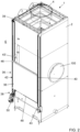
- the abatement filter 1 can be integrated into a leather processing line, and preferably it can be positioned in the vicinity of a leather treatment chamber, and in particular in the vicinity of a chamber, in which the leathers are sprayed at least a liquid substance, in order to achieve a suitable surface treatment.
- This in particular generates an aerosol 102 comprising a solid and/or liquid particulate in suspension in the air, which must be filtered before the air can be introduced into the environment outside the production line.
- the spraying chamber (not shown) is connected to the abatement filter 1 by means of an inlet duct 100.
- the inlet duct 100 is configured to allow the passage of the aerosol 102, in particular in a direction D.
- the inlet duct 100 ends inside a container 2 which substantially defines the abatement filter 1.
- the container 2 can be substantially closed and isolated from the outside except for the inlet duct 100 and an outlet duct 4, as will become clear later.
- the inlet duct 100 can represent the passage used by most, and preferably by all, the aerosol 102 to pass from the spray chamber to the external environment E.
- the container 2 has a substantially vertical development, at the in order to limit the horizontal dimensions inside the production line in which it is inserted.
- the leathers are never inside the container 2.
- the container 2 can be external and separate from the processing line along which the leathers pass.
- the inlet duct 100 can be fluidically connected to a suction device configured to generate a flow of fluids, and in particular of aerosols 102, from the spray chamber towards the inside of the container 2 and subsequently towards the outlet duct 4.
- a suction device configured to generate a flow of fluids, and in particular of aerosols 102, from the spray chamber towards the inside of the container 2 and subsequently towards the outlet duct 4.
- said suction device can be positioned inside the container 2, or, alternatively, it can be positioned outside the container 2 but be fluidically connected with it.
- the suction device can be constituted by a centrifugal impeller 10, driven by a motor 3.
- the outlet duct 4 can have a substantially smaller section than that of the container 2, in order to facilitate the exit of said aerosol. 102 from the container itself.
- the abatement filter comprises a liquid filter, indicated as a whole with the number 5.
- the liquid filter 5 comprises at least a first nozzle 6 positioned inside the inlet duct 100 configured to spray a first liquid on said aerosol 102, so as to achieve a first abatement of the particulate present in suspension.
- the first nozzle 6 can be positioned in equi-flow or counter-flow with respect to the aerosol flow 102 inside the inlet duct 100 in order to improve its filtering efficiency.
- the first nozzle 6 can be in equi-flow if the nozzle has a small diameter, so as to limit its clogging.
- the first liquid sprayed by the first nozzle 6 can be water.
- a plurality of first nozzles 6 can be present, which can be positioned, according to the direction of advance of the aerosol, substantially in sequence, or substantially in parallel.
- a fan 10 configured to direct the aerosol flow 102 upwards can be present at and/or near the end of the inlet duct 100 which leads into the container 1.
- the fan 10 is of the radial type.
- the inlet duct 100 has an opening which allows the aerosol 102 to diffuse inside the container 2, thanks to the action of the fan 10, and also allows the solid and/or liquid particulate to fall down.
- the water recovery system 12 comprises a sludge deposit basin 14, in which the solid and/or liquid particulate that falls from the inlet duct 100 is deposited.
- a suitable filter 18 can be provided on the suction side of said pump 16, configured to block the solid components from the outside, in order to prevent clogging of the nozzles.
- the liquid filter 5 can comprise at least a second nozzle 22, and preferably a plurality of second nozzles 22, positioned in position higher than the end of said inlet duct 100 and configured to spray a fluid, preferably said first liquid, and more preferably water, in counter-flow with respect to the direction of advance of said aerosol 102.
- said second nozzles 22 can be fed by said water recovery system 12, for example by means of a conduit 24, which starts from said pump 16, and which preferably can be the same conduit that also feeds the first nozzle 6.
- the inlet duct 100 it can occupy only a part of the section of the container 2, so as to allow the fluid sprayed by said second uge IIi to fall and be collected in said basin 14.
- the abatement filter 1 comprises a dry filter, indicated as a whole with the number 26.
- the dry filter is configured to allow the passage of the aerosol 102 through a plurality of small passages in order to allow the solid and/or liquid particulate to be deposited.
- the dry filter 26 is arranged downstream from the liquid filter 5 with respect to the forward motion of the aerosol 102 inside the abatement filter 1.
- the dry filter 26 can comprise at least one body filter filling body 28, configured to perform a first dry filtration of the aerosol 102.
- the filling body filter 28 can comprise a layer of filling bodies 30, for example balls or complex objects with curved and/or flat surfaces, preferably made of plastic material with a rough surface, which trap the solid particles that are suspended in the aerosol 102.
- said filling bodies 30 can be contained inside a suitable casing 31.
- said dry filter 26 can be provided with one or more third nozzles (not shown), which allow to wash the filling bodies 30, in order to remove the particles and solids deposited on their surface.
- the dry filter 26 can comprise, downstream of said filler bodies 30 filter 28, one or more labyrinth filters 32, configured to pass the aerosol 102 through a plurality of narrow passages, in order to to cause condensation of the liquid and/or solid suspension present in said aerosol on the walls of the passages of the filter 32.
- these labyrinth filters 32 can be made of metal sheet.
- the outlet duct 4 can be placed downstream of said labyrinth filters 32 and can have a smaller section than the rest of the container 2, in order to improve the upward flow of aerosol 102.
- the filtering apparatus 34 comprises at least one laminar filter element 36, having laminar shape - ie in which two dimensions, i.e. length and width, are much greater than the thickness, i.e. the dimension which is substantially transverse to the direction of the aerosol flow 102 - made in flexible filter material, for example in fabric, or in TNT, preferably obtained starting from natural or vegetable fibers, or in filter paper.
- the filter element 36 can be made of metal fibers, or of plastic fibers.
- the filter element 36 has dimensions length and width - substantially corresponding to those of the container section 2.
- the filter element 36 can have larger dimensions than the section of the outlet duct 4, so as to allow covering the duct itself, and in particular it can have dimensions equal to twice the section of the outlet duct.
- the filter element 36 has a size greater than half of the section of the container 2, in order to allow adequate filtration of the aerosol 102.
- the filter element 36 has a dimension less than twice the section of the container 2, in order to achieve effective aerosol filtration but at the same time to avoid excessive waste of space.
- the filter element has dimensions between half and double the section of the container 2 in correspondence with the portion in which the filter element itself is positioned.
- the filtering apparatus 34 comprises a movement assembly 38 configured to move said filter element 36 between a first operating position and a second rest position.
- Said first operating position is a position in which said filter element is located between the spraying chamber and the external environment, and is positioned in correspondence with the passage mainly traveled by the aerosol in order to exit the spraying chamber towards the external environment E.
- the second rest position is a position in which said filter element is not located between the spraying chamber and the external environment, and is not positioned in correspondence with the passage mainly crossed by the aerosol in order to exit the spraying chamber towards the external environment E.
- the filtering element 36 is in a first position in which it is available and/or reachable by a user for its replacement, and it is not in a position to filter the aerosol 102 exiting said outlet duct 4.
- said second position can be along one of the sides of the container 2, and preferably it can be along a side perpendicular to the arrival side of the inlet duct 100.
- said second position can be at a height that can be easily reached by a user.
- the movement assembly 38 can be configured to make the filter element 36 travel a first horizontal section, in order to remove it from said first operating position, and a second vertical section, in order to bring it to correspondence with said second rest position.
- the container 2 can comprise a suitable slot 39 configured to allow the passage of said filter element 36 between said first and said second position.
- the filter element 36 can be associated, preferably in a reversible manner, to said movement assembly 38 by means of a support structure 37 which comprises a plurality of support elements 40 configured to associate said filter element 36 to said movement assembly 38.
- said support elements can comprise a plurality of guides, or a plurality of gripping elements, for example a plurality of grippers, or a plurality of buttons.
- said support elements can in turn be associated with a frame (not shown) associated with said movement assembly.
- the support structure 37 is integral with the filter element 36, and in particular can be moved by the movement assembly 38 between a first position in which the filter element 36 is in a position suitable for filtering the aerosol 102, and a second position in which the filter element 36 is in a position not suitable for filtering the aerosol 102.
- said second position can be a position in which the filter element 36 can be easily separated and/or re-associated with the support structure 37, in order to be replaced.
- said support structure 37 is configured to associate said filter element 36 with movement means 42, consisting for example of a pair of conveyor belts or, preferably of a pair of chains 43, 43', which can be closed-loop, or open, for example, with winding at both ends.
- Said movement means 42 are configured to move said support elements 40, and therefore said filtering element 36, between said first and said second position.
- said support elements 40 can be associated with said chains 43, 43'by means of suitable pins.
- transverse support elements 46 positioned between the two chains 43, 43', in order to support the filter element 36.
- a closing element 48 of the slot 39 can be positioned in a more rearward position - ie closer to said second position with respect to said filter element, ie further upstream with respect to said filter element 36 in the displacement that goes from said second position at said first position -.
- said chains 43, 43' are moved by at least one actuator 50.
- the motion generated by said actuator 50 can be transmitted to the two chains 43, 43' by means of suitable transmission means.
- said actuator 50 can comprise an electric motor.
- said actuator 50 can be connected to a suitable control and processing unit (not shown).
- said chains 43, 43' are closed-loop, and are configured to be returned around a roller, preferably idle, positioned inside said container 2.
- the guide element can provide at the ends a pair of toothed wheels configured to engage the links of the chains 43, 43'.
- the transverse guiding element can have a diameter smaller than that of the toothed wheels so as to substantially not come into contact with the filtering element 36.
- said at least one guiding element can only be shown by the pair of toothed wheels which in this case can be rotatably secured by suitable mechanical means to the outer wall of the container 2.
- said movement means 42 can be configured to move said support structure 37 and/or said filter element 36 from said first position, in which the filter element is in a position suitable for filtering the aerosol 102 exiting said container 2, to said second position, in which the filter element is in a position not suitable for filtering the aerosol 102 leaving said container 2, and to a third position, in which the filter element 36 is in a position, which preferably is different from said second position and is not suitable for filtering the aerosol 102 exiting said container 2.
- said third position can be on a side that can be facing and/or angled with respect to that on which said second position is located.
- said third position can be substantially symmetrical with respect to said second position and in particular it can be positioned at the same height as said second position.
- the distance that the filter element 36 must travel between said first position and said second position and vice versa can be equal to the distance that the filter element must travel between said first position and said third position and vice versa.
- a further filter element 36' preferably associated with a further support structure 37'.
- said further filter element 36' can be connected to said movement assembly 38.
- said further filter element can be associated with a further movement assembly 38'.
- said further filter element 36' can be substantially similar to said filter element 36.
- said further movement assembly 38' can be substantially similar to said movement assembly 38.
- said further movement assembly 38' can be configured to move said further filter element 36'between a further first position, in which the further filter element 36' is positioned in a position suitable for filtering the aerosol 102 exiting said container 2, a further second position, in which the further element filter 36'is positioned in a position not suitable for filtering the aerosol 102 exiting said container 2, and a third position, which is preferably different from said second position and in which the further filter element 36' is positioned in a position not suitable for filtering the aerosol 102 exiting said container 2.
- said further first position can face said first position, and preferably in a higher position than said first position.
- said further first position can be in a lower position than said first position.
- said further second position can correspond to and/or be placed side by side and/or facing said second position.
- said further third position can correspond to and/or be placed side by side and/or facing said third position.
- said further movement assembly 38' can be associated with said container on a face which substantially faces the surface on which said movement assembly 38 is positioned. In a further embodiment said further movement assembly 38' can be associated with said container on a surface which is substantially angled with respect to the surface on which said movement assembly 38 is positioned.
- a grid can be positioned, for example made of metal, configured to prevent the filter element 36 from bending upwards under the thrust of the aerosol flow 102.
- the abatement filter 1 comprises at least one sensor of pressure 58, and preferably at least one pair of pressure sensors pressure 58, 60 configured to measure the pressure along the aerosol path 102.
- a first pressure sensor 58 can be positioned upstream of said filter element 36, while a second pressure sensor 60 can be positioned downstream of said filter element.
- both pressure sensors 58, 60 can be connected to the control and processing unit which controls the operation of the scrubber filter 1.
- control and processing unit can be configured to calculate the pressure variation upstream and downstream of said filter 34, in order to verify the proper functioning of the filter itself.
- control and processing unit can be configured to calculate the derivative of the pressure variation over time.
- said control and processing unit can be configured to send an alarm signal to a user if it detects a malfunction and/or detects saturation and/or clogging of the filter element 36.
- said control and processing unit can be configured to send an alarm signal to a user if it detects a malfunction and/or detects saturation and/or clogging of the filter element 36.
- they can be sent different signals.
- the aerosol 102 coming from the spraying chamber is sucked by the suction device through the inlet duct 100, where it receives a first spray of water from the first nozzle 6.
- the fan 10 directs it upwards.
- the second nozzles 22 spray a further jet of water onto the aerosol, in order to remove a further fraction of liquid and/or solid suspension.
- the water sprayed by the first nozzles 6 and/or the second nozzles 22 is collected in the basin 14, filtered by the filter 18 and conveyed by the pump 20 through the conduit 24 back to the first nozzles 6 and/or the second nozzles 22.
- the aerosol 102 can pass through the dry filter 26, releasing a further fraction of the liquid and/or solid suspension on the walls of said dry filter.
- the aerosol 102 can enter the outlet channel 4 and pass through the filter element 36 in order to release a further fraction of liquid and/or solid suspension.
- the suspension is trapped in the cavities present in the filter element 36, which can gradually become saturated, until it no longer allows the passage of the aerosol 102.
- control and processing unit can detect the control and processing unit on the basis of the pressure measurements carried out by sensors 58, 60.
- control and processing unit can be configured to send an alarm signal, informing that the filter element is clogged and requires maintenance or needs to be replaced.
- control and processing unit can be configured to send a different signal.
- the user can stop the operation of the production line and/or of the spraying chamber and/or of the abatement filter 1, and subsequently activate the movement assembly 38 in order to replace the filter element 36.
- the actuator 50 which activates the movement means 42 can be activated. In particular, in this way the filter element 36 is removed from said first operating position and moved towards said second rest position.
- the guide element comprises a transverse cylinder
- said filter element 36 can be configured to rest on the cylinder itself during the passage from said horizontal section to said vertical section, thus depositing on the guide element a part of the suspension which had been filtered.
- the guide element comprises a Teflon-coated cylinder
- the deposited suspension may not stick and fall to the ground.
- the filter element 36 When the filter element 36 is in said second position, the user can easily remove it from the movement assembly by acting on the support elements 40.
- said support elements 40 can be connected to said control and processing unit in order to allow the their control in an automated way.
- the user can reactivate the movement assembly 38 in order to move said filter element 36 from said second position to said first position.
- the closing element 48 is located in correspondence with the slot 39 substantially closing it.
- the user can reactivate the Abatement filter and/or the spray chamber and/or the production line.
- the filter element 36 can be washed in order to be reused.
- the movement assembly 38 is configured to move the filter element between said first, said second and said third position, and the operation is as follows.
- the further filter element 36' can be associated with the movement assembly in said second or said third position.
- said movement assembly 38 can be operated in order to move said filter element 36 towards said third or said second position, and in particular towards the position in which said further filter element 36'has not been associated.
- this movement of the movement means 42 involves simultaneously the movement of said further filter element 36'from said second or said third position up to said first position. In this way, the time during which there is no filter element 36, 36'in said first position can be considerably reduced, and therefore the time during which the filtration of the aerosol 102 in output from the abatement filter 1 does not take place, and this allows to reduce the time during which it is necessary to stop the filtering booth.
- the movement assembly 38 is operated in order to move the filter element 36 from said first position to said second or to said third position. Subsequently, the filter element 36 can be detached and replaced.
- the abatement filter according to the invention is particularly advantageous, indeed, optimal, since:
Landscapes
- Chemical & Material Sciences (AREA)
- Chemical Kinetics & Catalysis (AREA)
- Engineering & Computer Science (AREA)
- Manufacturing & Machinery (AREA)
- Mechanical Engineering (AREA)
- Organic Chemistry (AREA)
- Filtering Of Dispersed Particles In Gases (AREA)
Claims (15)
- Abluftfilter (1) zum Filtern des in einer Lederbehandlungs- und/oder - zurichtungskammer erzeugten Aerosols (102), wobei der Abluftfilter (1) einen Behälter (2) umfasst, durch den das zu filternde Aerosol (102) geleitet wird, wobei der Behälter (2) Folgendes enthält:- mindestens eine Absaugvorrichtung (3, 10), die so konfiguriert ist, dass sie das in der Lederbehandlungs- und/oder zurichtungskammer erzeugte Aerosol (102) absaugt,- mindestens einen Flüssigkeitsfilter (5), der so konfiguriert ist, dass er mindestens eine Flüssigkeit auf Wasserbasis auf das Aerosol (102) sprüht, um die im Aerosol selbst in Suspension befindlichen Partikel mindestens teilweise auszufällen,- eine Trockenfiltervorrichtung (34), die stromabwärts des Flüssigkeitsfilters (5) entsprechend der Strömungsrichtung des Aerosols (102) angeordnet ist und mindestens ein laminares Filterelement (36) umfasst,dadurch gekennzeichnet, dass das mindestens eine Filterelement (36) auf mechanisierte Weise zwischen einer ersten Betriebsposition, die zum Filtern des Aerosols (102) geeignet ist, wobei die erste Position den Weg des Aerosols (102) durch den Behälter (2) beeinträchtigt, und einer zweiten Nichtbetriebsposition, die nicht zum Filtern des Aerosols (102) geeignet ist, wobei die zweite Position den Weg nicht beeinträchtigt, beweglich ist.
- Abluftfilter nach Anspruch 1, dadurch gekennzeichnet, dass das Filterelement (36) Abmessungen - d. h. Länge und Breite - aufweist, die zwischen der Hälfte und dem Doppelten des Querschnitts des Behälters (2) in Übereinstimmung mit dem Bereich liegen, in dem das Filterelement (36) angeordnet ist, wenn es sich in seiner Betriebsposition befindet.
- Abluftfilter nach einem oder mehreren der vorstehenden Ansprüche, dadurch gekennzeichnet, dass das Filterelement (36):- in der ersten Betriebsposition, die zum Filtern des Aerosols (102) geeignet ist, in Übereinstimmung mit dem Abschnitt eines Auslasskanals (4) des Behälters (2) in die äußere Umgebung angeordnet ist,in der zweiten Nichtbetriebsstellung, die nicht zum Filtern des Aerosols (102) geeignet ist, nicht in Übereinstimmung mit dem Abschnitt des Auslasskanals (4) angeordnet ist.
- Abluftfilter nach einem oder mehreren der vorstehenden Ansprüche, dadurch gekennzeichnet, dass er mindestens eine Bewegungsbaugruppe (38) umfasst, die Folgendes umfasst:- mindestens eine, vorzugsweise zwei, geschlossene Ketten (43, 43') im geschlossenen Kreis, und/oder- mindestens eine, vorzugsweise zwei Ketten im offenen Kreis (43, 43').
- Abluftfilter nach einem oder mehreren der vorstehenden Ansprüche, dadurch gekennzeichnet, dass er eine Stützstruktur (37) umfasst, die eine Vielzahl von Stützelementen (40) umfasst, die so konfiguriert sind, dass sie das Filterelement (36) reversibel mit der Bewegungsbaugruppe (38) verbinden.
- Abluftfilter nach einem oder mehreren der Ansprüche 4 und 5, dadurch gekennzeichnet, dass die Bewegungsbaugruppe (38) einen Aktor (50) umfasst, der so konfiguriert ist, dass er Bewegungsmittel (42) betätigt, die das Filterelement (36) zwischen der ersten und der zweiten Position bewegen.
- Abluftfilter nach einem oder mehreren der Ansprüche 4 bis 6, dadurch gekennzeichnet, dass der Behälter (2), in dem das Filterelement (36) angeordnet ist, wenn es sich in der ersten Position befindet, einen Schlitz (39) umfasst, der den Durchgang des Filterelements (36) von der ersten Position in die zweite Position oder umgekehrt ermöglicht und der durch ein Verschlusselement (48) blockiert ist, wenn sich das Filterelement (36) in der ersten Position befindet.
- Abluftfilter nach einem oder mehreren der Ansprüche 4 bis 7, dadurch gekennzeichnet, dass er ein weiteres Filterelement (36') umfasst, das mit der Bewegungsbaugruppe (38) verbunden ist, die so konfiguriert ist, dass sie das Filterelement (36) und/oder das weitere Filterelement (36') zwischen der ersten Position, der zweiten Position und einer dritten Position bewegt, die sich von der zweiten Position unterscheidet und in der sich das Filterelement (36) und/oder das weitere Filterelement (36') in einer ungeeigneten Position zum Filtern des Aerosols (102) befindet.
- Abluftfilter nach Anspruch 8, dadurch gekennzeichnet, dass er eine weitere Bewegungsbaugruppe (38') umfasst, der das weitere Filterelement (36') zugeordnet ist, wobei die weitere Bewegungsbaugruppe so konfiguriert ist, dass sie das Filterelement (36) zwischen einer weiteren ersten Position, in der sich das weitere Filterelement (36') in einer geeigneten Position zum Filtern des Aerosols (102) am Auslass des Behälters (2) befindet, und einer weiteren zweiten oder einer weiteren dritten Position, in der sich das weitere Filterelement (36') in einer ungeeigneten Position zum Filtern des Aerosols (102) befindet, bewegt.
- Abluftfilter nach einem oder mehreren der vorstehenden Ansprüche, dadurch gekennzeichnet, dass er Folgendes umfasst:- einen ersten Drucksensor (58), der stromaufwärts des Filterelements (36) angeordnet ist,- einen zweiten Drucksensor (60), der stromabwärts des Filterelements (36) angeordnet ist,- eine Steuer- und Verarbeitungseinheit, die so konfiguriert ist, dass sie die Druckdifferenz stromaufwärts und stromabwärts des Filterelements (36) misst.
- Abluftfilter nach einem oder mehreren der vorstehenden Ansprüche, dadurch gekennzeichnet, dass das Filterelement (36) aus flexiblem Filtermaterial, z. B. aus Gewebe oder aus Vliesstoff besteht.
- Abluftfilter nach einem oder mehreren der vorstehenden Ansprüche, dadurch gekennzeichnet, dass die Trockenfiltervorrichtung (34) ferner Folgendes umfasst:- einen Filter mit Füllkörpern (28), umfassend Kugeln oder komplexe Objekte mit gekrümmten und/oder flachen Oberflächen, die in einem Gehäuse (31) enthalten sind und vorzugsweise aus Kunststoffmaterial mit rauer Oberfläche bestehen, die feste Partikel abfangen, die in dem Aerosol (102) in Suspension sind, oder- mindestens einen Labyrinthfilter (32), der so konfiguriert ist, dass er das Aerosol (102) durch eine Vielzahl von engen Durchgängen leitet, um die Kondensation der in dem Aerosol vorhandenen flüssigen und/oder festen Suspension an den Wänden der Durchgänge des Filters (32) selbst zu bewirkenund dass die Filterfüllkörper (28) und der Labyrinthfilter (32) stromaufwärts des Filterelements (36) angeordnet sind.
- Anlage zur Herstellung von Leder, umfassend eine Ledersprühkammer, dadurch gekennzeichnet, dass die Ledersprühkammer mit einem Abluftfilter (1) nach einem oder mehreren der vorstehenden Ansprüche fluidisch verbunden ist.
- Verfahren zur Verwendung eines Abluftfilters (1) nach einem oder mehreren der Ansprüche 1 bis 12, das den Austausch und/oder die Wartung des Filterelements (36) bereitstellt, wenn der Druck stromaufwärts und/oder der Druck stromabwärts des Filterelements selbst und/oder die Differenz zwischen den Drücken und/oder deren Veränderung im Laufe der Zeit vorher festgelegte Bedingungen und/oder vom Benutzer eingestellte Werte erfüllen.
- Verfahren zur Verwendung eines Abluftfilters (1) nach Anspruch 14, dadurch gekennzeichnet, dass das Filterelement (36) gewaschen und wiederverwendet wird.
Applications Claiming Priority (1)
| Application Number | Priority Date | Filing Date | Title |
|---|---|---|---|
| IT202000025465 | 2020-10-27 |
Publications (3)
| Publication Number | Publication Date |
|---|---|
| EP3992307A1 EP3992307A1 (de) | 2022-05-04 |
| EP3992307B1 true EP3992307B1 (de) | 2025-05-07 |
| EP3992307C0 EP3992307C0 (de) | 2025-05-07 |
Family
ID=74184752
Family Applications (1)
| Application Number | Title | Priority Date | Filing Date |
|---|---|---|---|
| EP21204683.3A Active EP3992307B1 (de) | 2020-10-27 | 2021-10-26 | Wäscherfilter und verfahren zu dessen verwendung |
Country Status (1)
| Country | Link |
|---|---|
| EP (1) | EP3992307B1 (de) |
Family Cites Families (5)
| Publication number | Priority date | Publication date | Assignee | Title |
|---|---|---|---|---|
| CN102553316A (zh) * | 2012-01-04 | 2012-07-11 | 无锡市新达轻工机械有限公司 | 转鼓用过滤装置 |
| CN207871905U (zh) * | 2018-01-23 | 2018-09-18 | 桐乡市高桥皮革有限责任公司 | 清洁化牛皮家具革废气排放机构 |
| CN209393009U (zh) * | 2018-11-01 | 2019-09-17 | 辛集市东贞皮业有限公司 | 一种清洁生产的皮革废气除臭系统 |
| CN110643752A (zh) * | 2019-10-16 | 2020-01-03 | 清远市腾翔皮革有限公司 | 一种皮革粉尘收集压缩装置 |
| CN211069616U (zh) | 2019-10-28 | 2020-07-24 | 漳州富洋皮业有限公司 | 皮革生产中废气净化除臭装置 |
-
2021
- 2021-10-26 EP EP21204683.3A patent/EP3992307B1/de active Active
Also Published As
| Publication number | Publication date |
|---|---|
| EP3992307A1 (de) | 2022-05-04 |
| EP3992307C0 (de) | 2025-05-07 |
Similar Documents
| Publication | Publication Date | Title |
|---|---|---|
| US20240042475A1 (en) | Device for removing wet paint overspray | |
| KR101321688B1 (ko) | 정화 장치를 구비한 도장 부스 | |
| KR101794038B1 (ko) | 선박평형수 처리장치 | |
| KR101708624B1 (ko) | 습윤 페인트 오버스프레이를 제거하기 위한 방법과 필터 장치 | |
| WO2014196238A1 (ja) | 浄化装置を備えた塗装ブース | |
| CA2622665A1 (en) | Device and method for separating wet paint overspray | |
| CN101306757A (zh) | 一种片式输送带及清洗装置 | |
| EP3992307B1 (de) | Wäscherfilter und verfahren zu dessen verwendung | |
| JP2023129745A (ja) | ガス状汚染物質処理設備 | |
| SE424606B (sv) | Sprutbox | |
| EP0407363B1 (de) | Selbstreinigender Unterdruckfilter mit dauerndem endlosem Bandfiltermedium, insbesondere zur Reinigung von industriellen Schmier- und Kühlflüssigkeiten | |
| JPH10165864A (ja) | 水溶性塗料の塗装装置 | |
| US4558657A (en) | Spraying apparatus | |
| KR102051460B1 (ko) | 도료 분진 집진장치 | |
| KR101130950B1 (ko) | 작업부스의 오염공기 여과 장치 | |
| JPH0337961B2 (de) | ||
| EP1332802A2 (de) | Lackspritzkabine | |
| KR101565761B1 (ko) | 집진 시스템 | |
| KR200479561Y1 (ko) | 이중에어커튼이 구비된 클린부스 | |
| EP2030696A1 (de) | Beschichtungsmaschine | |
| KR200175357Y1 (ko) | 연마 캐빈 내 스와프 적체 방지 장치 | |
| JP3688761B2 (ja) | スプレー式金属表面処理装置 | |
| JPH09253541A (ja) | 水溶性塗料用塗装装置 | |
| WO2018015901A1 (en) | Painting booth with mat filtering system for the overspray | |
| JP7741560B2 (ja) | 人孔内壁洗浄装置 |
Legal Events
| Date | Code | Title | Description |
|---|---|---|---|
| PUAI | Public reference made under article 153(3) epc to a published international application that has entered the european phase |
Free format text: ORIGINAL CODE: 0009012 |
|
| STAA | Information on the status of an ep patent application or granted ep patent |
Free format text: STATUS: THE APPLICATION HAS BEEN PUBLISHED |
|
| AK | Designated contracting states |
Kind code of ref document: A1 Designated state(s): AL AT BE BG CH CY CZ DE DK EE ES FI FR GB GR HR HU IE IS IT LI LT LU LV MC MK MT NL NO PL PT RO RS SE SI SK SM TR |
|
| STAA | Information on the status of an ep patent application or granted ep patent |
Free format text: STATUS: REQUEST FOR EXAMINATION WAS MADE |
|
| 17P | Request for examination filed |
Effective date: 20221028 |
|
| RBV | Designated contracting states (corrected) |
Designated state(s): AL AT BE BG CH CY CZ DE DK EE ES FI FR GB GR HR HU IE IS IT LI LT LU LV MC MK MT NL NO PL PT RO RS SE SI SK SM TR |
|
| P01 | Opt-out of the competence of the unified patent court (upc) registered |
Effective date: 20230518 |
|
| STAA | Information on the status of an ep patent application or granted ep patent |
Free format text: STATUS: EXAMINATION IS IN PROGRESS |
|
| 17Q | First examination report despatched |
Effective date: 20231030 |
|
| GRAP | Despatch of communication of intention to grant a patent |
Free format text: ORIGINAL CODE: EPIDOSNIGR1 |
|
| STAA | Information on the status of an ep patent application or granted ep patent |
Free format text: STATUS: GRANT OF PATENT IS INTENDED |
|
| INTG | Intention to grant announced |
Effective date: 20241218 |
|
| GRAS | Grant fee paid |
Free format text: ORIGINAL CODE: EPIDOSNIGR3 |
|
| GRAA | (expected) grant |
Free format text: ORIGINAL CODE: 0009210 |
|
| STAA | Information on the status of an ep patent application or granted ep patent |
Free format text: STATUS: THE PATENT HAS BEEN GRANTED |
|
| AK | Designated contracting states |
Kind code of ref document: B1 Designated state(s): AL AT BE BG CH CY CZ DE DK EE ES FI FR GB GR HR HU IE IS IT LI LT LU LV MC MK MT NL NO PL PT RO RS SE SI SK SM TR |
|
| REG | Reference to a national code |
Ref country code: GB Ref legal event code: FG4D |
|
| REG | Reference to a national code |
Ref country code: CH Ref legal event code: EP |
|
| REG | Reference to a national code |
Ref country code: DE Ref legal event code: R096 Ref document number: 602021030327 Country of ref document: DE |
|
| REG | Reference to a national code |
Ref country code: IE Ref legal event code: FG4D |
|
| U01 | Request for unitary effect filed |
Effective date: 20250526 |
|
| U07 | Unitary effect registered |
Designated state(s): AT BE BG DE DK EE FI FR IT LT LU LV MT NL PT RO SE SI Effective date: 20250603 |
|
| P04 | Withdrawal of opt-out of the competence of the unified patent court (upc) registered |
Free format text: CASE NUMBER: APP_25708/2025 Effective date: 20250528 |
|
| PG25 | Lapsed in a contracting state [announced via postgrant information from national office to epo] |
Ref country code: ES Free format text: LAPSE BECAUSE OF FAILURE TO SUBMIT A TRANSLATION OF THE DESCRIPTION OR TO PAY THE FEE WITHIN THE PRESCRIBED TIME-LIMIT Effective date: 20250507 |
|
| PG25 | Lapsed in a contracting state [announced via postgrant information from national office to epo] |
Ref country code: GR Free format text: LAPSE BECAUSE OF FAILURE TO SUBMIT A TRANSLATION OF THE DESCRIPTION OR TO PAY THE FEE WITHIN THE PRESCRIBED TIME-LIMIT Effective date: 20250808 Ref country code: NO Free format text: LAPSE BECAUSE OF FAILURE TO SUBMIT A TRANSLATION OF THE DESCRIPTION OR TO PAY THE FEE WITHIN THE PRESCRIBED TIME-LIMIT Effective date: 20250807 |
|
| PG25 | Lapsed in a contracting state [announced via postgrant information from national office to epo] |
Ref country code: PL Free format text: LAPSE BECAUSE OF FAILURE TO SUBMIT A TRANSLATION OF THE DESCRIPTION OR TO PAY THE FEE WITHIN THE PRESCRIBED TIME-LIMIT Effective date: 20250507 |
|
| PG25 | Lapsed in a contracting state [announced via postgrant information from national office to epo] |
Ref country code: HR Free format text: LAPSE BECAUSE OF FAILURE TO SUBMIT A TRANSLATION OF THE DESCRIPTION OR TO PAY THE FEE WITHIN THE PRESCRIBED TIME-LIMIT Effective date: 20250507 |
|
| PG25 | Lapsed in a contracting state [announced via postgrant information from national office to epo] |
Ref country code: RS Free format text: LAPSE BECAUSE OF FAILURE TO SUBMIT A TRANSLATION OF THE DESCRIPTION OR TO PAY THE FEE WITHIN THE PRESCRIBED TIME-LIMIT Effective date: 20250807 |
|
| PG25 | Lapsed in a contracting state [announced via postgrant information from national office to epo] |
Ref country code: IS Free format text: LAPSE BECAUSE OF FAILURE TO SUBMIT A TRANSLATION OF THE DESCRIPTION OR TO PAY THE FEE WITHIN THE PRESCRIBED TIME-LIMIT Effective date: 20250907 |
|
| U20 | Renewal fee for the european patent with unitary effect paid |
Year of fee payment: 5 Effective date: 20251016 |
|
| PGFP | Annual fee paid to national office [announced via postgrant information from national office to epo] |
Ref country code: GB Payment date: 20251016 Year of fee payment: 5 |
|
| PG25 | Lapsed in a contracting state [announced via postgrant information from national office to epo] |
Ref country code: SM Free format text: LAPSE BECAUSE OF FAILURE TO SUBMIT A TRANSLATION OF THE DESCRIPTION OR TO PAY THE FEE WITHIN THE PRESCRIBED TIME-LIMIT Effective date: 20250507 |
|
| PG25 | Lapsed in a contracting state [announced via postgrant information from national office to epo] |
Ref country code: CZ Free format text: LAPSE BECAUSE OF FAILURE TO SUBMIT A TRANSLATION OF THE DESCRIPTION OR TO PAY THE FEE WITHIN THE PRESCRIBED TIME-LIMIT Effective date: 20250507 |
|
| PG25 | Lapsed in a contracting state [announced via postgrant information from national office to epo] |
Ref country code: SK Free format text: LAPSE BECAUSE OF FAILURE TO SUBMIT A TRANSLATION OF THE DESCRIPTION OR TO PAY THE FEE WITHIN THE PRESCRIBED TIME-LIMIT Effective date: 20250507 |
|
| PLBE | No opposition filed within time limit |
Free format text: ORIGINAL CODE: 0009261 |
|
| STAA | Information on the status of an ep patent application or granted ep patent |
Free format text: STATUS: NO OPPOSITION FILED WITHIN TIME LIMIT |
|
| REG | Reference to a national code |
Ref country code: CH Ref legal event code: L10 Free format text: ST27 STATUS EVENT CODE: U-0-0-L10-L00 (AS PROVIDED BY THE NATIONAL OFFICE) Effective date: 20260318 |
|
| 26N | No opposition filed |
Effective date: 20260210 |