EP3992420A1 - Ensemble de garniture d'étanchéité de fond de puits - Google Patents
Ensemble de garniture d'étanchéité de fond de puits Download PDFInfo
- Publication number
- EP3992420A1 EP3992420A1 EP20204922.7A EP20204922A EP3992420A1 EP 3992420 A1 EP3992420 A1 EP 3992420A1 EP 20204922 A EP20204922 A EP 20204922A EP 3992420 A1 EP3992420 A1 EP 3992420A1
- Authority
- EP
- European Patent Office
- Prior art keywords
- tubular element
- expandable tubular
- metal
- downhole
- packer assembly
- Prior art date
- Legal status (The legal status is an assumption and is not a legal conclusion. Google has not performed a legal analysis and makes no representation as to the accuracy of the status listed.)
- Withdrawn
Links
- 229910052751 metal Inorganic materials 0.000 claims abstract description 90
- 239000002184 metal Substances 0.000 claims abstract description 90
- 239000000463 material Substances 0.000 claims abstract description 36
- 229920001971 elastomer Polymers 0.000 claims abstract description 28
- 238000006073 displacement reaction Methods 0.000 claims abstract description 16
- 239000007788 liquid Substances 0.000 claims abstract description 11
- 239000012530 fluid Substances 0.000 claims description 25
- VYPSYNLAJGMNEJ-UHFFFAOYSA-N Silicium dioxide Chemical compound O=[Si]=O VYPSYNLAJGMNEJ-UHFFFAOYSA-N 0.000 claims description 13
- 241000446313 Lamella Species 0.000 claims description 10
- 239000000853 adhesive Substances 0.000 claims description 8
- 230000001070 adhesive effect Effects 0.000 claims description 8
- 239000003973 paint Substances 0.000 claims description 7
- 239000000806 elastomer Substances 0.000 claims description 6
- 239000000377 silicon dioxide Substances 0.000 claims description 6
- 239000000835 fiber Substances 0.000 claims description 5
- 239000000203 mixture Substances 0.000 claims description 5
- 229910052582 BN Inorganic materials 0.000 claims description 3
- PZNSFCLAULLKQX-UHFFFAOYSA-N Boron nitride Chemical compound N#B PZNSFCLAULLKQX-UHFFFAOYSA-N 0.000 claims description 3
- 229910001092 metal group alloy Inorganic materials 0.000 claims description 3
- 239000002121 nanofiber Substances 0.000 claims description 3
- 239000002071 nanotube Substances 0.000 claims description 3
- TWNQGVIAIRXVLR-UHFFFAOYSA-N oxo(oxoalumanyloxy)alumane Chemical compound O=[Al]O[Al]=O TWNQGVIAIRXVLR-UHFFFAOYSA-N 0.000 claims description 3
- 235000012239 silicon dioxide Nutrition 0.000 claims description 3
- 229910052845 zircon Inorganic materials 0.000 claims description 3
- GFQYVLUOOAAOGM-UHFFFAOYSA-N zirconium(iv) silicate Chemical compound [Zr+4].[O-][Si]([O-])([O-])[O-] GFQYVLUOOAAOGM-UHFFFAOYSA-N 0.000 claims description 3
- 239000003921 oil Substances 0.000 description 9
- 239000002245 particle Substances 0.000 description 6
- 239000007789 gas Substances 0.000 description 5
- 230000000712 assembly Effects 0.000 description 4
- 238000000429 assembly Methods 0.000 description 4
- VNWKTOKETHGBQD-UHFFFAOYSA-N methane Chemical compound C VNWKTOKETHGBQD-UHFFFAOYSA-N 0.000 description 4
- 230000004888 barrier function Effects 0.000 description 3
- 239000008187 granular material Substances 0.000 description 3
- XLYOFNOQVPJJNP-UHFFFAOYSA-N water Substances O XLYOFNOQVPJJNP-UHFFFAOYSA-N 0.000 description 3
- 239000000919 ceramic Substances 0.000 description 2
- 239000010779 crude oil Substances 0.000 description 2
- 239000003345 natural gas Substances 0.000 description 2
- 229910002110 ceramic alloy Inorganic materials 0.000 description 1
- 239000002131 composite material Substances 0.000 description 1
- 239000004020 conductor Substances 0.000 description 1
- 238000007599 discharging Methods 0.000 description 1
- 238000001125 extrusion Methods 0.000 description 1
- 239000003292 glue Substances 0.000 description 1
- 239000011499 joint compound Substances 0.000 description 1
- 238000004519 manufacturing process Methods 0.000 description 1
- 238000012986 modification Methods 0.000 description 1
- 230000004048 modification Effects 0.000 description 1
- 238000005086 pumping Methods 0.000 description 1
- 239000004576 sand Substances 0.000 description 1
- 238000007789 sealing Methods 0.000 description 1
- 239000000126 substance Substances 0.000 description 1
Images

Classifications
-
- E—FIXED CONSTRUCTIONS
- E21—EARTH OR ROCK DRILLING; MINING
- E21B—EARTH OR ROCK DRILLING; OBTAINING OIL, GAS, WATER, SOLUBLE OR MELTABLE MATERIALS OR A SLURRY OF MINERALS FROM WELLS
- E21B43/00—Methods or apparatus for obtaining oil, gas, water, soluble or meltable materials or a slurry of minerals from wells
- E21B43/02—Subsoil filtering
- E21B43/10—Setting of casings, screens, liners or the like in wells
- E21B43/103—Setting of casings, screens, liners or the like in wells of expandable casings, screens, liners, or the like
- E21B43/105—Expanding tools specially adapted therefor
-
- E—FIXED CONSTRUCTIONS
- E21—EARTH OR ROCK DRILLING; MINING
- E21B—EARTH OR ROCK DRILLING; OBTAINING OIL, GAS, WATER, SOLUBLE OR MELTABLE MATERIALS OR A SLURRY OF MINERALS FROM WELLS
- E21B33/00—Sealing or packing boreholes or wells
- E21B33/10—Sealing or packing boreholes or wells in the borehole
- E21B33/12—Packers; Plugs
- E21B33/129—Packers; Plugs with mechanical slips for hooking into the casing
- E21B33/1295—Packers; Plugs with mechanical slips for hooking into the casing actuated by fluid pressure
- E21B33/12955—Packers; Plugs with mechanical slips for hooking into the casing actuated by fluid pressure using drag blocks frictionally engaging the inner wall of the well
-
- E—FIXED CONSTRUCTIONS
- E21—EARTH OR ROCK DRILLING; MINING
- E21B—EARTH OR ROCK DRILLING; OBTAINING OIL, GAS, WATER, SOLUBLE OR MELTABLE MATERIALS OR A SLURRY OF MINERALS FROM WELLS
- E21B23/00—Apparatus for displacing, setting, locking, releasing or removing tools, packers or the like in boreholes or wells
- E21B23/04—Apparatus for displacing, setting, locking, releasing or removing tools, packers or the like in boreholes or wells operated by fluid means, e.g. actuated by explosion
- E21B23/0412—Apparatus for displacing, setting, locking, releasing or removing tools, packers or the like in boreholes or wells operated by fluid means, e.g. actuated by explosion characterised by pressure chambers, e.g. vacuum chambers
Definitions
- the present invention relates to a downhole packer assembly for expansion of a metal sleeve, such as a metal patch, in a well downhole in a well tubular metal structure.
- the invention also relates to a downhole system comprising the downhole packer assembly and a positive displacement pump for expanding the expandable tubular element.
- the liquid between the radially expanding patch and the inner face of the well tubular metal structure may be trapped since the liquid cannot escape through any openings, such as leaks or perforations.
- Such entrapped liquid in a pocket between the metal patch and the well tubular metal structure hinders full expansion of the patch and thus prevents that the patch can seal properly against the inner face of the well tubular metal structure.
- a downhole packer assembly for expansion of a metal sleeve, such as a metal patch, in a well downhole in a well tubular metal structure, comprising:
- the expandable tubular element may be made of elastomer or rubber and is an expandable elastomeric or rubber tubular element.
- the friction-enhancing material may be grains, such as individual grains.
- the grains may be embedded in an outer material face of the elastomeric or rubber material of the expandable tubular element, the outer material face forming the outer face of the expandable tubular element.
- the grains may be adhered to the outer face of the expandable tubular element.
- the friction-enhancing material may be a friction-enhancing layer.
- the friction-enhancing layer may be an adhesive or paint.
- the friction-enhancing layer may comprise a mixture of grains and an adhesive or paint.
- the friction-enhancing layer may be applied on the outer face of the expandable tubular element.
- the body part may have an opening for providing fluid communication to the expandable space in order to expand the expandable tubular element.
- the grains may be made of silicon dioxide (SiO 2 ), zirconium silicate (ZrSiO 4 ), aluminium oxide (Al 2 O 3 ), cubic boron nitride (cBN) or metal alloy.
- the grains may comprise ceramics.
- the expandable tubular element may comprise metal enhancement, such as metal strips, metal lamellas or slats, a weave or mesh structure, or a metal grid.
- the expandable tubular element may comprise metal enhancement, such as strips, slats, lamellas, a weave or mesh structure, or a grid, where the strips, slats, lamellas, a weave or mesh structure, or a grid are made of metal, a composite, fibre material, etc.
- metal strips, metal lamellas or metal slats may extend axially along the body part or circumferentially around the body part.
- the expandable tubular element may comprise a packer-reinforcement layer having at least one fibre layer, a wire, a cable, a nanofibre, a nanotube and/or a nanoparticle-modified elastomer.
- metal strips, metal lamellas or slats, a weave or mesh structure, or a metal grid may be embedded in the elastomeric or rubber material.
- the packer may comprise metal coil springs arranged in grooves of the outer face.
- the downhole packer assembly may be an inflatable packer being constructed with a packer-reinforcement layer having at least one fibre layer.
- the fibre layers may provide both mechanical and anti-extrusion properties in a relatively simple and small package.
- the invention relates to a downhole system comprising the above downhole packer assembly and a positive displacement pump for expanding the expandable tubular element.
- the downhole system may comprise at least one metal sleeve arranged around the expandable tubular element.
- the downhole system may comprise a driving unit, such as an electric motor, for driving the pump.
- a driving unit such as an electric motor
- the downhole system may comprise a downhole tractor for propelling the downhole system forward in the well.
- gray is meant any physical particle or small entity.
- grains is thus meant granules or individual particles.
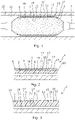
- Fig. 1 shows a downhole packer assembly 1 for expansion of a metal sleeve, such as a metal patch 10, in a well 11 downhole in a well tubular metal structure 12.
- the downhole packer assembly 1 comprises a body part 2 surrounded by an expandable tubular element 3 having two ends being connected with the body part 2, providing an expandable space 4 (shown in Fig. 2 ) therebetween.
- the expandable space 4 is fillable with liquid during such expansion.
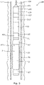
- the expandable tubular element 3 has an outer face 5 and an inner face 6 shown in Fig. 2 .
- the expandable tubular element 3 comprises an elastomeric or rubber material 18 having a friction coefficient, and the expandable tubular element 3 comprises a friction-enhancing material 17 providing a higher friction coefficient of the outer face than the friction coefficient of the elastomeric or rubber material 18.
- the friction coefficient may be measured according to the standard ASTM G115 - 10(2018) "Standard Guide for Measuring and Reporting Friction Coefficients ".
- the downhole packer assembly 1 is arranged inside the metal patch/sleeve 10 to be expanded so that the metal patch 10 surrounds the expandable tubular element 3 and so that the metal patch 10 expands as the expandable tubular element 3 expands.
- the metal patch 10 is shown in a cross-sectional view in both Figs. 1 and 5 to illustrate that the metal patch 10 encloses the packer assembly 1 and expands as the expandable tubular element 3 expands.
- the expandable tubular element 3 is shown in a partly expanded condition, and the dotted line is to illustrate the position of the fully expanded metal patch 10.
- the expandable tubular element 3 is shown in an unexpanded condition.
- the metal patch 10 is expanded more equally, and no pockets are formed between the inner face of the well tubular metal structure 12 and the outer face of the metal patch 10. This is due to the fact that the pointwise expansion of the metal patch 10 is controlled so that no area point is expanded substantially more than another area point of the metal patch 10.
- the friction between the metal patch 10 and the expandable tubular element 3 ensures that one area point of the metal patch cannot be expanded more than another area point as compared to when less friction is present because in that case the metal patch 10 can freely expand more in some areas than in others, which creates cracks as the metal patch 10 is thinned too much in these freely expanded areas.
- the higher friction between the outer face of the expandable tubular element 3 and the inner face of the metal patch 10 limits free expansion and limits the possibility of some areas thinning more than others.
- the body part 2 of the downhole packer assembly 1 has an opening 16 for providing fluid communication to the expandable space 4 in order to expand the expandable tubular element 3.
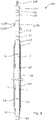
- the downhole system 100 comprising the downhole packer assembly 1 also comprises a positive displacement pump 101 for pumping liquid into the expandable space 4 to expand the expandable tubular element 3.
- the positive displacement pump 101 is connected to the top via a wireline 104 and a cable head 109.
- the positive displacement pump 101 comprises an electrical control 105.
- the positive displacement pump 101 comprises a motor 106 driving the second pump 21.
- the positive displacement pump 101 further comprises a compensator 107 for keeping a predetermined overpressure in the positive displacement pump 101 compared to the surrounding pressure.
- the positive displacement pump 101 further comprises a first chamber 99 arranged in the housing 93, and the first chamber 99 has a first outlet 110 in fluid communication with the pump outlet 98 for delivering the increased pressure in a confined space 88 downhole.
- a first piston 111 is movable in the first chamber 99 for pressing fluid out of the pump outlet 98, and a driving means 112 is configured to drive the first piston 111 in a reciprocating movement in a first direction or an opposite second direction in the first chamber 99.
- the first piston 111 divides the first chamber 99 into a first chamber part and a second chamber part 115.
- the first chamber part comprises the first outlet 110 and a first inlet 116.
- a first valve 117 is arranged in the first outlet 110 for allowing fluid to flow out of the first chamber part and preventing fluid from flowing into the first chamber part
- a second valve 118 is arranged in the first inlet 116 for allowing fluid to flow into the first chamber part and preventing fluid from flowing out of the first chamber part.
- the positive displacement pump 101 further comprises a control unit 20 for controlling an output of the driving means 112 to the movement of the first piston 111 in the first direction or the second direction.
- the positive displacement pump 101 may be a single-acting or, as shown in Fig. 4 , a double-acting downhole positive displacement pump. In Fig.
- the driving means 112 is a second pump 21, and in order to drive the first piston 111, the first piston is connected to a piston rod 28, and a second piston 29 is connected to another part of the piston rod 28, and the second pump 21 pumps fluid into a second chamber 30 in which the second piston 29 is movable in the first direction and the opposite second direction.
- the second piston 29 moves in the second chamber 30, it moves the first piston 111 back and forth, and in this way liquid is pumped into e.g. the expandable tubular element 3 of the packer assembly 1 to inflate the expandable tubular element 3.
- the second piston 29 divides the second chamber 30 into a first chamber part 31 and a second chamber part 32, and the first chamber part 31 comprises a first aperture 33, and the second chamber part 32 comprises a second aperture 34.
- the second pump 21 has a discharge opening 35 fluidly connected with the first aperture 33 in a first position and fluidly connected with the second aperture 34 in a second position via the control unit 20 being a flow control unit.
- the control unit 20 directs the fluid from the discharge opening 35 to either the first aperture 33 or the second aperture 34 for moving the second piston 29 in the second chamber 30 in the first direction or the second direction, respectively.
- the second pump 21 thus merely pumps fluid into the control unit 20, and the control unit 20 directs the fluid into the first chamber part 31 of the second chamber 30 to drive the first piston 11 away from the pump outlet 8 and into the second chamber part 32 of the second chamber 30 to drive the first piston 111 towards the pump outlet 98.
- the fluid in the first chamber 99 is well fluid, and the fluid in the second chamber 30 is tool fluid only flowing in the pump.
- the second pump 21 is thus a feed pump.
- the driving means 112 may be a drillpipe or drill string for supplying pressurised fluid from the surface to drive the piston back and forth in the chamber.
- the positive displacement pump 101 further comprises a discharge control unit 60 for discharging fluid in the expandable tubular element 3 of the packer assembly 1 in order to deflate the expandable tubular element 3.
- the packer assembly 1 is shown in its deflated position.
- the discharge control unit 90 may be a flow-operated discharge control unit 90.
- the discharge control unit 90 comprises an electrically operated valve, which is operated through an electrical conductor passing through the housing to open a discharge outlet 91 of fluid in the packer out into the well in order to deflate the expandable tubular element 3 of the packer assembly 1.
- the metal patch 10 is expanded for sealing off an opening/leak 86, shown in Fig. 5 , in the well tubular metal structure 12.
- the expandable tubular element 3 of the packer assembly 1 is connected to the body part 2 by connecting sleeves 87.
- the expandable tubular element 3 shown in Fig. 1 is made of elastomer or rubber and is an expandable elastomeric or rubber tubular element.
- the friction-enhancing material 17 is grains 15, such as individual grains, and the expandable tubular element 3 is made of elastomer or rubber 18. The grains 15 are adhered to the outer face of the expandable tubular element 3.
- the friction-enhancing material is a friction-enhancing layer 7, and the friction-enhancing layer 7 is an adhesive 14 or paint.
- the friction-enhancing layer 7 comprises a mixture of grains 15 and an adhesive 14 or paint and is an additional layer on the outer material face of the elastomeric or rubber material of the expandable tubular element 3.
- the grains may be applied as individual particles in a paint, glue or other type of adhesive, or the grains may be applied after the adhesive is applied on the outer material face of the elastomeric or rubber material of the expandable tubular element 3.
- the grains are embedded in an outer material face of the elastomeric or rubber material of the expandable tubular element 3, and the outer material face forms the outer face of the expandable tubular element 3.
- the friction-enhancing layer 7 is applied on the outer face of the expandable elastomeric or rubber material 18 of the expandable tubular element 3.
- the grains may be made of silicon dioxide (SiO 2 ), zirconium silicate (ZrSiO 4 ), aluminium oxide (Al 2 O 3 ), cubic boron nitride (cBN), ceramic or metal alloy.
- the grains may be sand particles.
- grain is meant any physical particle or small entity. By “grains” is thus meant granule/granules or individual particles.
- the expandable tubular element 3 may comprise metal enhancement, such as metal strips, metal lamellas, metal slats, a weave or mesh structure, or a metal grid.
- the metal strips, metal lamellas or metal slats extend axially along the body part 2 or circumferentially around the body part 2 so as to be able to expand with the expandable tubular element 3 and deflate again after expanding the metal patch 10.
- the metal strips, metal lamellas, metal slats, weave or mesh structure, or metal grid may be embedded in the elastomeric or rubber material or added as an additional layer.
- the expandable tubular element 3 may also comprise a packer-reinforcement layer having fibres, a wire, a cable, a nanofibre, a nanotube and/or a nanoparticle-modified elastomer.
- the packer further comprises metal coil springs arranged in grooves of the outer face.
- the downhole system 100 comprises two packer assemblies 1 mounted with a tool part having an opening between them, and a metal patch 10 is arranged in an overlapping manner with the packers forming a confined space 88, which is pressurised together with the packer assemblies 1 to expand the patch by letting liquid out through the openings 16 and also into the confined space 88 between the packer assemblies 1 and the metal patch 10. In this way, a longer metal patch can be expanded than by means of one packer assembly.
- fluid or "well fluid” is meant any kind of fluid that may be present in oil or gas wells downhole, such as natural gas, oil, oil mud, crude oil, water, etc.
- gas is meant any kind of gas composition present in a well, completion or open hole, and by “oil” is meant any kind of oil composition, such as crude oil, an oil-containing fluid, etc.
- Oil and water fluids may thus all comprise other elements or substances than gas, oil and/or water, respectively.
- annular barrier an annular barrier comprising a tubular metal part mounted as part of the well tubular metal structure and an expandable metal sleeve surrounding and connected to the tubular part defining an annular barrier space.
- casing or “well tubular metal structure” is meant any kind of pipe, tubing, tubular, liner, string, etc., used downhole in relation to oil or natural gas production.
- a downhole tractor 112B as shown in Fig. 6 can be used to push the tool/downhole system all the way into position in the well.
- the downhole tractor 112B may have projectable arms 110B having wheels 111B, wherein the wheels 111B contact the inner surface of the casing for propelling the tractor and the tool forward in the casing.
- a downhole tractor is any kind of driving tool capable of pushing or pulling tools in a well downhole, such as a Well Tractor ® .
Landscapes
- Geology (AREA)
- Life Sciences & Earth Sciences (AREA)
- Engineering & Computer Science (AREA)
- Mining & Mineral Resources (AREA)
- Environmental & Geological Engineering (AREA)
- Fluid Mechanics (AREA)
- Physics & Mathematics (AREA)
- General Life Sciences & Earth Sciences (AREA)
- Geochemistry & Mineralogy (AREA)
- Earth Drilling (AREA)
- Piles And Underground Anchors (AREA)
- Pipe Accessories (AREA)
- Consolidation Of Soil By Introduction Of Solidifying Substances Into Soil (AREA)
Priority Applications (6)
| Application Number | Priority Date | Filing Date | Title |
|---|---|---|---|
| EP20204922.7A EP3992420A1 (fr) | 2020-10-30 | 2020-10-30 | Ensemble de garniture d'étanchéité de fond de puits |
| AU2021367992A AU2021367992A1 (en) | 2020-10-30 | 2021-10-29 | Downhole packer assembly |
| CN202180070605.6A CN116324119A (zh) | 2020-10-30 | 2021-10-29 | 井下封隔器组件 |
| US17/514,410 US11708740B2 (en) | 2020-10-30 | 2021-10-29 | Downhole packer assembly |
| EP21802318.2A EP4237657A1 (fr) | 2020-10-30 | 2021-10-29 | Ensemble garniture d'étanchéité de fond de trou |
| PCT/EP2021/080180 WO2022090496A1 (fr) | 2020-10-30 | 2021-10-29 | Ensemble garniture d'étanchéité de fond de trou |
Applications Claiming Priority (1)
| Application Number | Priority Date | Filing Date | Title |
|---|---|---|---|
| EP20204922.7A EP3992420A1 (fr) | 2020-10-30 | 2020-10-30 | Ensemble de garniture d'étanchéité de fond de puits |
Publications (1)
| Publication Number | Publication Date |
|---|---|
| EP3992420A1 true EP3992420A1 (fr) | 2022-05-04 |
Family
ID=73043052
Family Applications (2)
| Application Number | Title | Priority Date | Filing Date |
|---|---|---|---|
| EP20204922.7A Withdrawn EP3992420A1 (fr) | 2020-10-30 | 2020-10-30 | Ensemble de garniture d'étanchéité de fond de puits |
| EP21802318.2A Withdrawn EP4237657A1 (fr) | 2020-10-30 | 2021-10-29 | Ensemble garniture d'étanchéité de fond de trou |
Family Applications After (1)
| Application Number | Title | Priority Date | Filing Date |
|---|---|---|---|
| EP21802318.2A Withdrawn EP4237657A1 (fr) | 2020-10-30 | 2021-10-29 | Ensemble garniture d'étanchéité de fond de trou |
Country Status (5)
| Country | Link |
|---|---|
| US (1) | US11708740B2 (fr) |
| EP (2) | EP3992420A1 (fr) |
| CN (1) | CN116324119A (fr) |
| AU (1) | AU2021367992A1 (fr) |
| WO (1) | WO2022090496A1 (fr) |
Families Citing this family (2)
| Publication number | Priority date | Publication date | Assignee | Title |
|---|---|---|---|---|
| CN118669122B (zh) * | 2023-03-14 | 2025-09-02 | 中国石油天然气股份有限公司 | 一种电动找漏验窜管柱及找漏工艺 |
| US20250243755A1 (en) * | 2024-01-29 | 2025-07-31 | Saudi Arabian Oil Company | Pinhole repair method using epoxy and expandable mesh |
Citations (4)
| Publication number | Priority date | Publication date | Assignee | Title |
|---|---|---|---|---|
| GB1458096A (en) * | 1973-06-25 | 1976-12-08 | Chevron Res | Impression packer |
| US20030196795A1 (en) * | 2002-04-17 | 2003-10-23 | Andrew Kutac | Inflatable packer with prestressed bladder |
| US20070261847A1 (en) * | 2004-09-13 | 2007-11-15 | Saltel Industries | Sealing Device for Plugging a Pipe or a Well |
| US20190226299A1 (en) * | 2018-01-25 | 2019-07-25 | Welltec Oilfield Solutions Ag | Downhole wireline intervention tool |
Family Cites Families (19)
| Publication number | Priority date | Publication date | Assignee | Title |
|---|---|---|---|---|
| US2187635A (en) * | 1938-05-23 | 1940-01-16 | George F Stamps | Well packer |
| US3085627A (en) * | 1958-08-15 | 1963-04-16 | Lynes Inc | Inflatable packer or element |
| US3104717A (en) * | 1961-09-25 | 1963-09-24 | Jersey Prod Res Co | Well packer |
| US3175618A (en) * | 1961-11-06 | 1965-03-30 | Pan American Petroleum Corp | Apparatus for placing a liner in a vessel |
| US5242019A (en) * | 1992-05-18 | 1993-09-07 | Baker Hughes Incorporated | Downhole tool with increased friction surface and method of manufacture |
| US5404946A (en) * | 1993-08-02 | 1995-04-11 | The United States Of America As Represented By The Secretary Of The Interior | Wireline-powered inflatable-packer system for deep wells |
| US5507341A (en) * | 1994-12-22 | 1996-04-16 | Dowell, A Division Of Schlumberger Technology Corp. | Inflatable packer with bladder shape control |
| US5613555A (en) * | 1994-12-22 | 1997-03-25 | Dowell, A Division Of Schlumberger Technology Corporation | Inflatable packer with wide slat reinforcement |
| GB0303152D0 (en) * | 2003-02-12 | 2003-03-19 | Weatherford Lamb | Seal |
| US8894069B2 (en) * | 2005-03-30 | 2014-11-25 | Schlumberger Technology Corporation | Inflatable packers |
| ES2464457T3 (es) * | 2009-01-12 | 2014-06-02 | Welltec A/S | Barrera anular y sistema de barrera anular |
| US8613317B2 (en) * | 2009-11-03 | 2013-12-24 | Schlumberger Technology Corporation | Downhole piston pump and method of operation |
| EP2702248A4 (fr) * | 2011-06-24 | 2015-08-05 | Services Petroliers Schlumberger | Agencements de drain de pompe destinés à des systèmes de garniture d'étanchéité et procédés permettant d'échantillonner des formations souterraines à l'aide de ceux-ci |
| EP2586963A1 (fr) * | 2011-10-28 | 2013-05-01 | Welltec A/S | Matériau de fermeture pour barrières annulaires |
| US9169724B2 (en) * | 2012-02-23 | 2015-10-27 | Halliburton Energy Services, Inc. | Expandable conical tubing run through production tubing and into open hole |
| US10584564B2 (en) * | 2014-11-17 | 2020-03-10 | Terves, Llc | In situ expandable tubulars |
| EP3415711A1 (fr) * | 2017-06-13 | 2018-12-19 | Welltec A/S | Outil de pose de pièce rapportée de fond de trou |
| US11898422B2 (en) * | 2020-11-03 | 2024-02-13 | Saudi Arabian Oil Company | Diamond coating on the cone for expandable tubulars |
| US11585176B2 (en) * | 2021-03-23 | 2023-02-21 | Saudi Arabian Oil Company | Sealing cracked cement in a wellbore casing |
-
2020
- 2020-10-30 EP EP20204922.7A patent/EP3992420A1/fr not_active Withdrawn
-
2021
- 2021-10-29 AU AU2021367992A patent/AU2021367992A1/en not_active Abandoned
- 2021-10-29 CN CN202180070605.6A patent/CN116324119A/zh active Pending
- 2021-10-29 US US17/514,410 patent/US11708740B2/en active Active
- 2021-10-29 WO PCT/EP2021/080180 patent/WO2022090496A1/fr not_active Ceased
- 2021-10-29 EP EP21802318.2A patent/EP4237657A1/fr not_active Withdrawn
Patent Citations (4)
| Publication number | Priority date | Publication date | Assignee | Title |
|---|---|---|---|---|
| GB1458096A (en) * | 1973-06-25 | 1976-12-08 | Chevron Res | Impression packer |
| US20030196795A1 (en) * | 2002-04-17 | 2003-10-23 | Andrew Kutac | Inflatable packer with prestressed bladder |
| US20070261847A1 (en) * | 2004-09-13 | 2007-11-15 | Saltel Industries | Sealing Device for Plugging a Pipe or a Well |
| US20190226299A1 (en) * | 2018-01-25 | 2019-07-25 | Welltec Oilfield Solutions Ag | Downhole wireline intervention tool |
Also Published As
| Publication number | Publication date |
|---|---|
| US20220136363A1 (en) | 2022-05-05 |
| EP4237657A1 (fr) | 2023-09-06 |
| AU2021367992A1 (en) | 2023-06-22 |
| CN116324119A (zh) | 2023-06-23 |
| WO2022090496A1 (fr) | 2022-05-05 |
| US11708740B2 (en) | 2023-07-25 |
Similar Documents
| Publication | Publication Date | Title |
|---|---|---|
| US10557317B2 (en) | Systems and methods for pipe concentricity, zonal isolation, and stuck pipe prevention | |
| EP3759313B1 (fr) | Pompe submersible électrique à système de ventilation de gaz | |
| US6779601B2 (en) | Inflatable packing element | |
| US10378532B2 (en) | Positive displacement plunger pump with gas escape valve | |
| US20040251019A1 (en) | Bottom discharge seal section | |
| US20130068311A1 (en) | Through Tubing Pumping System With Automatically Deployable and Retractable Seal | |
| WO1994023177A1 (fr) | Procede et appareil de reduction des forces engendrees par le differentiel de pression et s'exerçant sur l'outil de forage d'un puits jaillissant | |
| AU2003209251A1 (en) | Inflatable packing element | |
| US11708740B2 (en) | Downhole packer assembly | |
| AU2021354892B2 (en) | Downhole positive displacement pump | |
| CN110234836B (zh) | 带罩电潜泵 | |
| US20160076550A1 (en) | Redundant ESP Seal Section Chambers | |
| WO2016191578A1 (fr) | Pince multifonction | |
| US11851974B1 (en) | Resettable packer system for pumping operations | |
| WO2022016023A2 (fr) | Dispositif de poussée hydraulique | |
| US8419387B1 (en) | Bag seal mounting plate with breather tube | |
| NO20220877A1 (en) | Frac plug high expansion element retainer | |
| US10947811B2 (en) | Systems and methods for pipe concentricity, zonal isolation, and stuck pipe prevention | |
| US20130251547A1 (en) | Liquid Lift Pumps for Gas Wells | |
| CN116867952A (zh) | 用于金属对金属密封的可折叠壳体封隔器 | |
| GB2399367A (en) | Inflatable packer with control line | |
| CN211648095U (zh) | 一种锚定过流装置 |
Legal Events
| Date | Code | Title | Description |
|---|---|---|---|
| PUAI | Public reference made under article 153(3) epc to a published international application that has entered the european phase |
Free format text: ORIGINAL CODE: 0009012 |
|
| STAA | Information on the status of an ep patent application or granted ep patent |
Free format text: STATUS: THE APPLICATION HAS BEEN PUBLISHED |
|
| AK | Designated contracting states |
Kind code of ref document: A1 Designated state(s): AL AT BE BG CH CY CZ DE DK EE ES FI FR GB GR HR HU IE IS IT LI LT LU LV MC MK MT NL NO PL PT RO RS SE SI SK SM TR |
|
| STAA | Information on the status of an ep patent application or granted ep patent |
Free format text: STATUS: THE APPLICATION IS DEEMED TO BE WITHDRAWN |
|
| 18D | Application deemed to be withdrawn |
Effective date: 20221105 |