EP3992467A1 - Erosionsreduzierender zweiteiliger labyrinthdichtungsgegenring - Google Patents
Erosionsreduzierender zweiteiliger labyrinthdichtungsgegenring Download PDFInfo
- Publication number
- EP3992467A1 EP3992467A1 EP21206130.3A EP21206130A EP3992467A1 EP 3992467 A1 EP3992467 A1 EP 3992467A1 EP 21206130 A EP21206130 A EP 21206130A EP 3992467 A1 EP3992467 A1 EP 3992467A1
- Authority
- EP
- European Patent Office
- Prior art keywords
- seal
- impeller
- airflow
- compressor
- compressor assembly
- Prior art date
- Legal status (The legal status is an assumption and is not a legal conclusion. Google has not performed a legal analysis and makes no representation as to the accuracy of the status listed.)
- Pending
Links
Images


Classifications
-
- F—MECHANICAL ENGINEERING; LIGHTING; HEATING; WEAPONS; BLASTING
- F04—POSITIVE - DISPLACEMENT MACHINES FOR LIQUIDS; PUMPS FOR LIQUIDS OR ELASTIC FLUIDS
- F04D—NON-POSITIVE-DISPLACEMENT PUMPS
- F04D17/00—Radial-flow pumps, e.g. centrifugal pumps; Helico-centrifugal pumps
- F04D17/08—Centrifugal pumps
- F04D17/10—Centrifugal pumps for compressing or evacuating
-
- F—MECHANICAL ENGINEERING; LIGHTING; HEATING; WEAPONS; BLASTING
- F04—POSITIVE - DISPLACEMENT MACHINES FOR LIQUIDS; PUMPS FOR LIQUIDS OR ELASTIC FLUIDS
- F04D—NON-POSITIVE-DISPLACEMENT PUMPS
- F04D29/00—Details, component parts, or accessories
- F04D29/05—Shafts or bearings, or assemblies thereof, specially adapted for elastic fluid pumps
- F04D29/056—Bearings
-
- B—PERFORMING OPERATIONS; TRANSPORTING
- B64—AIRCRAFT; AVIATION; COSMONAUTICS
- B64D—EQUIPMENT FOR FITTING IN OR TO AIRCRAFT; FLIGHT SUITS; PARACHUTES; ARRANGEMENT OR MOUNTING OF POWER PLANTS OR PROPULSION TRANSMISSIONS IN AIRCRAFT
- B64D13/00—Arrangements or adaptations of air-treatment apparatus for aircraft crew or passengers, or freight space
- B64D13/02—Arrangements or adaptations of air-treatment apparatus for aircraft crew or passengers, or freight space the air being pressurised
-
- F—MECHANICAL ENGINEERING; LIGHTING; HEATING; WEAPONS; BLASTING
- F01—MACHINES OR ENGINES IN GENERAL; ENGINE PLANTS IN GENERAL; STEAM ENGINES
- F01D—NON-POSITIVE DISPLACEMENT MACHINES OR ENGINES, e.g. STEAM TURBINES
- F01D11/00—Preventing or minimising internal leakage of working-fluid, e.g. between stages
- F01D11/02—Preventing or minimising internal leakage of working-fluid, e.g. between stages by non-contact sealings, e.g. of labyrinth type
-
- F—MECHANICAL ENGINEERING; LIGHTING; HEATING; WEAPONS; BLASTING
- F04—POSITIVE - DISPLACEMENT MACHINES FOR LIQUIDS; PUMPS FOR LIQUIDS OR ELASTIC FLUIDS
- F04D—NON-POSITIVE-DISPLACEMENT PUMPS
- F04D25/00—Pumping installations or systems
- F04D25/02—Units comprising pumps and their driving means
- F04D25/06—Units comprising pumps and their driving means the pump being electrically driven
-
- F—MECHANICAL ENGINEERING; LIGHTING; HEATING; WEAPONS; BLASTING
- F04—POSITIVE - DISPLACEMENT MACHINES FOR LIQUIDS; PUMPS FOR LIQUIDS OR ELASTIC FLUIDS
- F04D—NON-POSITIVE-DISPLACEMENT PUMPS
- F04D29/00—Details, component parts, or accessories
- F04D29/08—Sealings
- F04D29/10—Shaft sealings
- F04D29/102—Shaft sealings especially adapted for elastic fluid pumps
-
- F—MECHANICAL ENGINEERING; LIGHTING; HEATING; WEAPONS; BLASTING
- F04—POSITIVE - DISPLACEMENT MACHINES FOR LIQUIDS; PUMPS FOR LIQUIDS OR ELASTIC FLUIDS
- F04D—NON-POSITIVE-DISPLACEMENT PUMPS
- F04D29/00—Details, component parts, or accessories
- F04D29/08—Sealings
- F04D29/16—Sealings between pressure and suction sides
- F04D29/161—Sealings between pressure and suction sides especially adapted for elastic fluid pumps
- F04D29/162—Sealings between pressure and suction sides especially adapted for elastic fluid pumps of a centrifugal flow wheel
-
- F—MECHANICAL ENGINEERING; LIGHTING; HEATING; WEAPONS; BLASTING
- F16—ENGINEERING ELEMENTS AND UNITS; GENERAL MEASURES FOR PRODUCING AND MAINTAINING EFFECTIVE FUNCTIONING OF MACHINES OR INSTALLATIONS; THERMAL INSULATION IN GENERAL
- F16J—PISTONS; CYLINDERS; SEALINGS
- F16J15/00—Sealings
- F16J15/44—Free-space packings
- F16J15/447—Labyrinth packings
-
- F—MECHANICAL ENGINEERING; LIGHTING; HEATING; WEAPONS; BLASTING
- F16—ENGINEERING ELEMENTS AND UNITS; GENERAL MEASURES FOR PRODUCING AND MAINTAINING EFFECTIVE FUNCTIONING OF MACHINES OR INSTALLATIONS; THERMAL INSULATION IN GENERAL
- F16J—PISTONS; CYLINDERS; SEALINGS
- F16J15/00—Sealings
- F16J15/44—Free-space packings
- F16J15/447—Labyrinth packings
- F16J15/4472—Labyrinth packings with axial path
-
- F—MECHANICAL ENGINEERING; LIGHTING; HEATING; WEAPONS; BLASTING
- F05—INDEXING SCHEMES RELATING TO ENGINES OR PUMPS IN VARIOUS SUBCLASSES OF CLASSES F01-F04
- F05D—INDEXING SCHEME FOR ASPECTS RELATING TO NON-POSITIVE-DISPLACEMENT MACHINES OR ENGINES, GAS-TURBINES OR JET-PROPULSION PLANTS
- F05D2240/00—Components
- F05D2240/50—Bearings
-
- F—MECHANICAL ENGINEERING; LIGHTING; HEATING; WEAPONS; BLASTING
- F05—INDEXING SCHEMES RELATING TO ENGINES OR PUMPS IN VARIOUS SUBCLASSES OF CLASSES F01-F04
- F05D—INDEXING SCHEME FOR ASPECTS RELATING TO NON-POSITIVE-DISPLACEMENT MACHINES OR ENGINES, GAS-TURBINES OR JET-PROPULSION PLANTS
- F05D2240/00—Components
- F05D2240/55—Seals
Definitions
- Exemplary embodiments pertain to the art of environmental control units for, for example, aircraft.
- the cabin and/or other areas are pressurized by an electrically-driven cabin air compressor (CAC).
- CAC cabin air compressor
- the cabin air compressor takes in air flow at atmospheric pressure from outside the aircraft and compresses the airflow to a comfortable pressure for the aircraft cabin. This compressed air flow is then directed into the cabin.
- erosion damage occurs to a bearing support housing downstream of the compressor impeller. This erosion damage occurs when foreign object particles bypass a labyrinth seal between the impeller and the bearing support housing and subsequently impact the bearing support housing. Such erosion of the bearing support housing shortens the service life of the bearing support housing specifically and the cabin air compressor in general.
- a compressor assembly in one embodiment, includes an impeller rotatable about a central axis, and a seal assembly.
- the seal assembly includes a labyrinth seal defining a seal interface with a sealing element of the impeller, and a seal support ring into which the labyrinth seal is installed.
- the seal support includes a deflector ramp fluidly downstream of the seal interface. The deflector ramp is configured to turn an airflow leaking through the seal interface radially inwardly toward the central axis.
- the seal support ring further includes a plurality of circumferentially spaced teeth configured to diffuse a tangential component of the airflow.
- the plurality of circumferentially spaced teeth trap foreign object particles from the airflow between adjacent teeth of the circumferentially spaced teeth.
- the deflector ramp extends radially inboard of a radial location of the seal interface.
- the labyrinth seal is formed from a first, relatively soft material and the seal support ring is formed from a second, relatively hard material.
- the compressor assembly includes a shaft operably connected to the impeller, and a bearing assembly.
- the bearing assembly includes a bearing supportive of the shaft and a bearing support housing into which the bearing assembly is installed.
- the seal support ring is located axially between the impeller and the bearing support housing.
- the deflector ramp deflects the airflow from impacting on the bearing support housing.
- the seal support ring is installed to the bearing support housing.
- the sealing element of the impeller is located at a sealing flange of the impeller extending axially from the impeller.
- cabin air compressor in another embodiment, includes a compressor housing having an inlet and an outlet, and an impeller located in the housing.
- the impeller is rotatable about a central axis and is configured to compress an airflow directed through the inlet and direct the compressed airflow to the outlet.
- a seal assembly includes a labyrinth seal defining a seal interface with a sealing element of the impeller, and a seal support ring into which the labyrinth seal is installed.
- the seal support includes a deflector ramp fluidly downstream of the seal interface. The deflector ramp is configured to turn an airflow leaking through the seal interface radially inwardly toward the central axis.
- the seal support ring further includes a plurality of circumferentially spaced teeth configured to diffuse a tangential component of the airflow.
- the plurality of circumferentially spaced teeth trap foreign object particles from the airflow between adjacent teeth of the circumferentially spaced teeth.
- the deflector ramp extends radially inboard of a radial location of the seal interface.
- the labyrinth seal is formed from a first, relatively soft material and the seal support ring is formed from a second, relatively hard material.
- the cabin air compressor includes a shaft operably connected to the impeller, and a bearing assembly.
- the bearing assembly includes a bearing supportive of the shaft, and a bearing support housing into which the bearing assembly is installed.
- the seal support ring is located axially between the impeller and the bearing support housing.
- the deflector ramp deflects the airflow from impacting on the bearing support housing.
- the seal support ring is installed to the bearing support housing.
- an electrical motor is operably connected to the shaft to drive rotation of the impeller about the central axis.
- the sealing element of the impeller is located at a sealing flange of the impeller extending axially from the impeller.
- the compressed airflow is directed from the outlet to a cabin of an aircraft.
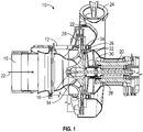
- the cabin air compressor 10 includes a compressor housing 12 in which a compressor impeller 14 is located.
- the compressor impeller 14 is driven by a shaft 16.
- the shaft 16 is driven by a power source, which in some embodiments is an electric motor 20.
- Airflow 22 at ambient pressure enters the cabin air compressor 10 at an inlet 18 and is urged across the compressor impeller 14 and compressed.
- the compressed airflow 22 then is directed through an outlet 24 to a selected location, for example, aircraft cabin 26.
- the shaft 16 and compressor impeller 14 are supported by a bearing 28, which is installed in a bearing support housing 30 located in the compressor housing 12.
- a labyrinth seal 32 is located at an impeller outer perimeter 34 to prevent airflow from leaking past the impeller outer perimeter 34.
- the labyrinth seal 32 is installed in and supported by a labyrinth seal mating ring 36 installed to the bearing support housing 30.
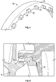
- this labyrinth seal mating ring 36 includes features to prevent erosion of the bearing support housing 30.
- the labyrinth seal mating ring 36 is a ring structure, having a ring outer surface 38, which mates to the bearing support housing 30. While illustrated as a complete ring, in some embodiments the labyrinth seal mating ring 36 may be a circumferentially segmented structure.
- the labyrinth seal 32 is located at a ring inner surface 42, substantially opposite to the ring outer surface 38. In some embodiments, the labyrinth seal mating ring 36 is formed from a relatively hard material, while the labyrinth seal 32 is formed from a relatively soft material.
- the labyrinth seal 32 when installed, the labyrinth seal 32 is located at a corresponding impeller sealing surface 44 of the compressor impeller 14.
- the impeller sealing surface 44 is located at a sealing flange 46 extending from a downstream side 48 of the compressor impeller 14 opposite an upstream side 50 relative to the location of the inlet 18.
- the labyrinth seal 32 and the impeller sealing surface 44 define a seal interface 52.
- the labyrinth seal mating ring 36 includes a deflector ramp 54 extending radially inboard from the ring inner surface 42.
- the deflector ramp 54 extends radially inboard of a radial location of the seal interface 52.
- the deflector ramp 54 is curvilinear such as shown in FIG. 3 , while in other embodiments the deflector ramp 54 may be another shape, such as linear or some combination of curvilinear and linear.
- air flow 22 that leaks past the seal interface 52 as leakage airflow 56 is diverted radially inwardly by the deflector ramp 54, to reduce impact of the leakage airflow 56 and any included particles or foreign objects on a support wall 58 of the bearing support housing 30.
- Such diversion of the leakage airflow 56 by the deflector ramp 54 reduces erosion of the bearing support housing 30.
- the labyrinth seal mating ring 36 includes a plurality of circumferentially spaced teeth 60 extending axially from a downstream wall 62 of the labyrinth seal mating ring 36.
- the leakage airflow 56 typically has a significant tangential velocity component due to rotation of the compressor impeller 14.
- the teeth 60 reduce this tangential velocity component and trap foreign object particles between adjacent teeth 60 to reduce the erosion of the bearing support housing 30.
- the labyrinth seal mating ring 36 described herein reduces erosion of the bearing support housing 30 of the cabin air compressor 10, thus extending the service life of the bearing support housing 30 and the cabin air compressor 10 overall. Further, the labyrinth seal mating ring 36 is configured to be retrofittable into existing cabin air compressors 10, without the need to modify surrounding components.
Landscapes
- Engineering & Computer Science (AREA)
- General Engineering & Computer Science (AREA)
- Mechanical Engineering (AREA)
- Health & Medical Sciences (AREA)
- General Health & Medical Sciences (AREA)
- Pulmonology (AREA)
- Aviation & Aerospace Engineering (AREA)
- Structures Of Non-Positive Displacement Pumps (AREA)
- Sealing Using Fluids, Sealing Without Contact, And Removal Of Oil (AREA)
Applications Claiming Priority (1)
| Application Number | Priority Date | Filing Date | Title |
|---|---|---|---|
| US17/088,100 US20220136516A1 (en) | 2020-11-03 | 2020-11-03 | Erosion mitigating two piece labyrinth seal mating ring |
Publications (1)
| Publication Number | Publication Date |
|---|---|
| EP3992467A1 true EP3992467A1 (de) | 2022-05-04 |
Family
ID=78516577
Family Applications (1)
| Application Number | Title | Priority Date | Filing Date |
|---|---|---|---|
| EP21206130.3A Pending EP3992467A1 (de) | 2020-11-03 | 2021-11-03 | Erosionsreduzierender zweiteiliger labyrinthdichtungsgegenring |
Country Status (2)
| Country | Link |
|---|---|
| US (1) | US20220136516A1 (de) |
| EP (1) | EP3992467A1 (de) |
Cited By (1)
| Publication number | Priority date | Publication date | Assignee | Title |
|---|---|---|---|---|
| EP4043736A1 (de) * | 2021-02-16 | 2022-08-17 | Hamilton Sundstrand Corporation | Erosionsmindernder labyrinthdichtungspassring |
Citations (5)
| Publication number | Priority date | Publication date | Assignee | Title |
|---|---|---|---|---|
| US4459802A (en) * | 1978-01-02 | 1984-07-17 | A/S Kongsberg Vapenfabrikk | Bleedoff of gas diffusers in fluid flow machines |
| JPH05195999A (ja) * | 1991-08-03 | 1993-08-06 | Man B & W Diesel Gmbh | 半径流圧縮機ロータの動的安定化装置 |
| JP2017141691A (ja) * | 2016-02-08 | 2017-08-17 | 三菱重工業株式会社 | 遠心回転機械 |
| CN207004860U (zh) * | 2017-07-05 | 2018-02-13 | 沈阳鼓风机集团齿轮压缩机有限公司 | 一种聚烯烃装置用离心压缩机 |
| US20180100514A1 (en) * | 2016-10-10 | 2018-04-12 | Solar Turbines Incorporated | Swirl brakes for compressors with teeth-on-rotor seals |
Family Cites Families (6)
| Publication number | Priority date | Publication date | Assignee | Title |
|---|---|---|---|---|
| US4152092A (en) * | 1977-03-18 | 1979-05-01 | Swearingen Judson S | Rotary device with bypass system |
| US4385768A (en) * | 1979-07-19 | 1983-05-31 | Rotoflow Corporation, Inc. | Shaft mounting device and method |
| US7575421B2 (en) * | 2004-09-22 | 2009-08-18 | Hamilton Sundstrand Corporation | Integral motor cooling and compressor inlet |
| US7791238B2 (en) * | 2005-07-25 | 2010-09-07 | Hamilton Sundstrand Corporation | Internal thermal management for motor driven machinery |
| IT1403222B1 (it) * | 2010-12-30 | 2013-10-17 | Nuovo Pignone Spa | Sistemi e metodi per rastremazione del rompi-vortice |
| JP7074442B2 (ja) * | 2017-09-15 | 2022-05-24 | 三菱重工コンプレッサ株式会社 | 圧縮機 |
-
2020
- 2020-11-03 US US17/088,100 patent/US20220136516A1/en not_active Abandoned
-
2021
- 2021-11-03 EP EP21206130.3A patent/EP3992467A1/de active Pending
Patent Citations (5)
| Publication number | Priority date | Publication date | Assignee | Title |
|---|---|---|---|---|
| US4459802A (en) * | 1978-01-02 | 1984-07-17 | A/S Kongsberg Vapenfabrikk | Bleedoff of gas diffusers in fluid flow machines |
| JPH05195999A (ja) * | 1991-08-03 | 1993-08-06 | Man B & W Diesel Gmbh | 半径流圧縮機ロータの動的安定化装置 |
| JP2017141691A (ja) * | 2016-02-08 | 2017-08-17 | 三菱重工業株式会社 | 遠心回転機械 |
| US20180100514A1 (en) * | 2016-10-10 | 2018-04-12 | Solar Turbines Incorporated | Swirl brakes for compressors with teeth-on-rotor seals |
| CN207004860U (zh) * | 2017-07-05 | 2018-02-13 | 沈阳鼓风机集团齿轮压缩机有限公司 | 一种聚烯烃装置用离心压缩机 |
Cited By (1)
| Publication number | Priority date | Publication date | Assignee | Title |
|---|---|---|---|---|
| EP4043736A1 (de) * | 2021-02-16 | 2022-08-17 | Hamilton Sundstrand Corporation | Erosionsmindernder labyrinthdichtungspassring |
Also Published As
| Publication number | Publication date |
|---|---|
| US20220136516A1 (en) | 2022-05-05 |
Similar Documents
| Publication | Publication Date | Title |
|---|---|---|
| EP2064449B1 (de) | Molekularreibungspumpmechanismus | |
| US9976564B2 (en) | Multi-stage radial compressor unit comprising gas removal during a compressor stage | |
| EP3149287B1 (de) | Dichtungsvorrichtung für turbomaschinen | |
| CN102563074B (zh) | 空气循环机密封板和密封带 | |
| CN1878931A (zh) | 压缩机中的密封装置 | |
| US20180030992A1 (en) | Centrifugal compressor and geared centrifugal compressor | |
| KR20160140836A (ko) | 가변 피치 블레이드들이 있는 터빈 엔진 압축기 | |
| CN100398826C (zh) | 压缩机 | |
| JPWO2018142535A1 (ja) | 回転機械 | |
| CN101652590A (zh) | 具有受压唇部的双重密封 | |
| EP3992467A1 (de) | Erosionsreduzierender zweiteiliger labyrinthdichtungsgegenring | |
| US11486411B2 (en) | Seal assembly | |
| EP4043736A1 (de) | Erosionsmindernder labyrinthdichtungspassring | |
| US5456577A (en) | Centrifugal pump with resiliently biasing diffuser | |
| CN106687663B (zh) | 轴密封件、用于运行的方法 | |
| EP1571343A1 (de) | Motor-Verdichteraggregat für Kraftfahrzeuge | |
| KR20180108462A (ko) | 터보과급기용 압축기 | |
| JP4370232B2 (ja) | 流体シール機構を備えた流体機械 | |
| US20210381520A1 (en) | Coolant plug-in pump with sealing washer to minimize the sealing gap | |
| JPH06193591A (ja) | 遠心コンプレッサ | |
| KR101157319B1 (ko) | 진공 펌프 | |
| US8721261B2 (en) | Compressor cover for turbine engine having axial abutment | |
| EP4512993A1 (de) | Rotor eines gasturbinentriebwerks, turbine eines gasturbinentriebwerks und gasturbinentriebwerk | |
| US20260071631A1 (en) | Shut-off valve and vacuum pump | |
| EP4513005A1 (de) | Labyrinthdichtung und entfernung aus einem gasturbinenmotor |
Legal Events
| Date | Code | Title | Description |
|---|---|---|---|
| PUAI | Public reference made under article 153(3) epc to a published international application that has entered the european phase |
Free format text: ORIGINAL CODE: 0009012 |
|
| STAA | Information on the status of an ep patent application or granted ep patent |
Free format text: STATUS: THE APPLICATION HAS BEEN PUBLISHED |
|
| AK | Designated contracting states |
Kind code of ref document: A1 Designated state(s): AL AT BE BG CH CY CZ DE DK EE ES FI FR GB GR HR HU IE IS IT LI LT LU LV MC MK MT NL NO PL PT RO RS SE SI SK SM TR |
|
| STAA | Information on the status of an ep patent application or granted ep patent |
Free format text: STATUS: REQUEST FOR EXAMINATION WAS MADE |
|
| 17P | Request for examination filed |
Effective date: 20221104 |
|
| RBV | Designated contracting states (corrected) |
Designated state(s): AL AT BE BG CH CY CZ DE DK EE ES FI FR GB GR HR HU IE IS IT LI LT LU LV MC MK MT NL NO PL PT RO RS SE SI SK SM TR |
|
| STAA | Information on the status of an ep patent application or granted ep patent |
Free format text: STATUS: EXAMINATION IS IN PROGRESS |
|
| 17Q | First examination report despatched |
Effective date: 20240404 |