EP3992500A1 - Soupape d'expansion électronique - Google Patents
Soupape d'expansion électronique Download PDFInfo
- Publication number
- EP3992500A1 EP3992500A1 EP20832134.9A EP20832134A EP3992500A1 EP 3992500 A1 EP3992500 A1 EP 3992500A1 EP 20832134 A EP20832134 A EP 20832134A EP 3992500 A1 EP3992500 A1 EP 3992500A1
- Authority
- EP
- European Patent Office
- Prior art keywords
- valve needle
- screw rod
- spring
- electronic expansion
- washer
- Prior art date
- Legal status (The legal status is an assumption and is not a legal conclusion. Google has not performed a legal analysis and makes no representation as to the accuracy of the status listed.)
- Pending
Links
- 239000000725 suspension Substances 0.000 claims description 34
- 230000002093 peripheral effect Effects 0.000 claims description 9
- 238000007789 sealing Methods 0.000 description 15
- 239000011248 coating agent Substances 0.000 description 8
- 238000000576 coating method Methods 0.000 description 8
- 238000003466 welding Methods 0.000 description 8
- 230000006835 compression Effects 0.000 description 6
- 238000007906 compression Methods 0.000 description 6
- OKTJSMMVPCPJKN-UHFFFAOYSA-N Carbon Chemical compound [C] OKTJSMMVPCPJKN-UHFFFAOYSA-N 0.000 description 4
- 229910002804 graphite Inorganic materials 0.000 description 4
- 239000010439 graphite Substances 0.000 description 4
- 230000001050 lubricating effect Effects 0.000 description 4
- CWQXQMHSOZUFJS-UHFFFAOYSA-N molybdenum disulfide Chemical compound S=[Mo]=S CWQXQMHSOZUFJS-UHFFFAOYSA-N 0.000 description 4
- 229910052982 molybdenum disulfide Inorganic materials 0.000 description 4
- -1 polytetrafluoroethylene Polymers 0.000 description 4
- 229920001343 polytetrafluoroethylene Polymers 0.000 description 4
- 239000004810 polytetrafluoroethylene Substances 0.000 description 4
- 238000006073 displacement reaction Methods 0.000 description 3
- 238000000034 method Methods 0.000 description 3
- 230000004048 modification Effects 0.000 description 2
- 238000012986 modification Methods 0.000 description 2
- 238000005057 refrigeration Methods 0.000 description 2
- 230000009471 action Effects 0.000 description 1
- 230000008859 change Effects 0.000 description 1
- 238000005516 engineering process Methods 0.000 description 1
- 238000007667 floating Methods 0.000 description 1
- 239000012530 fluid Substances 0.000 description 1
- 238000010438 heat treatment Methods 0.000 description 1
- 238000000465 moulding Methods 0.000 description 1
- 239000007921 spray Substances 0.000 description 1
Images





Classifications
-
- F—MECHANICAL ENGINEERING; LIGHTING; HEATING; WEAPONS; BLASTING
- F16—ENGINEERING ELEMENTS AND UNITS; GENERAL MEASURES FOR PRODUCING AND MAINTAINING EFFECTIVE FUNCTIONING OF MACHINES OR INSTALLATIONS; THERMAL INSULATION IN GENERAL
- F16K—VALVES; TAPS; COCKS; ACTUATING-FLOATS; DEVICES FOR VENTING OR AERATING
- F16K1/00—Lift valves or globe valves, i.e. cut-off apparatus with closure members having at least a component of their opening and closing motion perpendicular to the closing faces
- F16K1/02—Lift valves or globe valves, i.e. cut-off apparatus with closure members having at least a component of their opening and closing motion perpendicular to the closing faces with screw-spindle
-
- F—MECHANICAL ENGINEERING; LIGHTING; HEATING; WEAPONS; BLASTING
- F16—ENGINEERING ELEMENTS AND UNITS; GENERAL MEASURES FOR PRODUCING AND MAINTAINING EFFECTIVE FUNCTIONING OF MACHINES OR INSTALLATIONS; THERMAL INSULATION IN GENERAL
- F16K—VALVES; TAPS; COCKS; ACTUATING-FLOATS; DEVICES FOR VENTING OR AERATING
- F16K31/00—Actuating devices; Operating means; Releasing devices
- F16K31/44—Mechanical actuating means
- F16K31/50—Mechanical actuating means with screw-spindle or internally threaded actuating means
-
- F—MECHANICAL ENGINEERING; LIGHTING; HEATING; WEAPONS; BLASTING
- F16—ENGINEERING ELEMENTS AND UNITS; GENERAL MEASURES FOR PRODUCING AND MAINTAINING EFFECTIVE FUNCTIONING OF MACHINES OR INSTALLATIONS; THERMAL INSULATION IN GENERAL
- F16K—VALVES; TAPS; COCKS; ACTUATING-FLOATS; DEVICES FOR VENTING OR AERATING
- F16K1/00—Lift valves or globe valves, i.e. cut-off apparatus with closure members having at least a component of their opening and closing motion perpendicular to the closing faces
- F16K1/32—Details
- F16K1/34—Cutting-off parts, e.g. valve members, seats
- F16K1/36—Valve members
- F16K1/38—Valve members of conical shape
-
- F—MECHANICAL ENGINEERING; LIGHTING; HEATING; WEAPONS; BLASTING
- F16—ENGINEERING ELEMENTS AND UNITS; GENERAL MEASURES FOR PRODUCING AND MAINTAINING EFFECTIVE FUNCTIONING OF MACHINES OR INSTALLATIONS; THERMAL INSULATION IN GENERAL
- F16K—VALVES; TAPS; COCKS; ACTUATING-FLOATS; DEVICES FOR VENTING OR AERATING
- F16K1/00—Lift valves or globe valves, i.e. cut-off apparatus with closure members having at least a component of their opening and closing motion perpendicular to the closing faces
- F16K1/32—Details
- F16K1/48—Attaching valve members to screw-spindles
-
- F—MECHANICAL ENGINEERING; LIGHTING; HEATING; WEAPONS; BLASTING
- F16—ENGINEERING ELEMENTS AND UNITS; GENERAL MEASURES FOR PRODUCING AND MAINTAINING EFFECTIVE FUNCTIONING OF MACHINES OR INSTALLATIONS; THERMAL INSULATION IN GENERAL
- F16K—VALVES; TAPS; COCKS; ACTUATING-FLOATS; DEVICES FOR VENTING OR AERATING
- F16K1/00—Lift valves or globe valves, i.e. cut-off apparatus with closure members having at least a component of their opening and closing motion perpendicular to the closing faces
- F16K1/32—Details
- F16K1/54—Arrangements for modifying the way in which the rate of flow varies during the actuation of the valve
-
- F—MECHANICAL ENGINEERING; LIGHTING; HEATING; WEAPONS; BLASTING
- F16—ENGINEERING ELEMENTS AND UNITS; GENERAL MEASURES FOR PRODUCING AND MAINTAINING EFFECTIVE FUNCTIONING OF MACHINES OR INSTALLATIONS; THERMAL INSULATION IN GENERAL
- F16K—VALVES; TAPS; COCKS; ACTUATING-FLOATS; DEVICES FOR VENTING OR AERATING
- F16K31/00—Actuating devices; Operating means; Releasing devices
- F16K31/02—Actuating devices; Operating means; Releasing devices electric; magnetic
- F16K31/04—Actuating devices; Operating means; Releasing devices electric; magnetic using a motor
- F16K31/047—Actuating devices; Operating means; Releasing devices electric; magnetic using a motor characterised by mechanical means between the motor and the valve, e.g. lost motion means reducing backlash, clutches, brakes or return means
-
- F—MECHANICAL ENGINEERING; LIGHTING; HEATING; WEAPONS; BLASTING
- F25—REFRIGERATION OR COOLING; COMBINED HEATING AND REFRIGERATION SYSTEMS; HEAT PUMP SYSTEMS; MANUFACTURE OR STORAGE OF ICE; LIQUEFACTION SOLIDIFICATION OF GASES
- F25B—REFRIGERATION MACHINES, PLANTS OR SYSTEMS; COMBINED HEATING AND REFRIGERATION SYSTEMS; HEAT PUMP SYSTEMS
- F25B41/00—Fluid-circulation arrangements
- F25B41/30—Expansion means; Dispositions thereof
- F25B41/31—Expansion valves
- F25B41/34—Expansion valves with the valve member being actuated by electric means, e.g. by piezoelectric actuators
- F25B41/35—Expansion valves with the valve member being actuated by electric means, e.g. by piezoelectric actuators by rotary motors, e.g. by stepping motors
-
- Y—GENERAL TAGGING OF NEW TECHNOLOGICAL DEVELOPMENTS; GENERAL TAGGING OF CROSS-SECTIONAL TECHNOLOGIES SPANNING OVER SEVERAL SECTIONS OF THE IPC; TECHNICAL SUBJECTS COVERED BY FORMER USPC CROSS-REFERENCE ART COLLECTIONS [XRACs] AND DIGESTS
- Y02—TECHNOLOGIES OR APPLICATIONS FOR MITIGATION OR ADAPTATION AGAINST CLIMATE CHANGE
- Y02B—CLIMATE CHANGE MITIGATION TECHNOLOGIES RELATED TO BUILDINGS, e.g. HOUSING, HOUSE APPLIANCES OR RELATED END-USER APPLICATIONS
- Y02B30/00—Energy efficient heating, ventilation or air conditioning [HVAC]
- Y02B30/70—Efficient control or regulation technologies, e.g. for control of refrigerant flow, motor or heating
Definitions
- An object of the present application is to provide an electronic expansion valve, and the spring of the valve needle screw rod assembly is not easy to deflect.
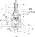
- FIG. 2 is a cross-sectional view of the first embodiment of the electronic expansion valve provided by the present application in a fully closed state.
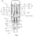
- the electronic expansion valve provided by the present application is composed of a valve body 20 and a stator coil 30.
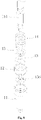
- the valve body 20 includes a valve needle screw rod assembly 1, a valve seat assembly 2, a nut assembly 3, a rotor assembly 4 and an outer shell 5.
- the stator coil 30 of the electronic expansion valve is connected to the drive controller. After the drive controller is energized, a pulse drive signal is sent to the stator coil 30.
- the stator coil 30 generates a periodically changing magnetic field, thereby driving the rotor assembly 4 of the electronic expansion valve to rotate in a forward direction or a reverse direction.
- the electronic expansion valve provided in this embodiment further includes the outer shell 5 with an open end, the outer shell 5 is mounted outside the rotor assembly 4.
- the opening of the outer shell 5 and the connecting seat 25 on the upper side of the valve seat assembly 2 are welded and sealed to form a closed accommodating cavity.
- the screw rod assembly 15 further includes an upper stop portion 155, and the upper stop portion 155 abuts against the spring 14.
- the screw rod assembly 15 includes an upper flange portion 1551, and the upper flange portion 1551 extends circumferentially along the surface of the screw rod 151.
- the upper flange portion 1551 and the screw rod 151 may be integrally formed, or they may be fixedly connected by welding, etc..
- the upper stop portion 155 is an upper flange portion 1551.
- the spring 14 is mounted around the screw rod 151, and the upper end of the spring 14 abuts against the upper stop portion 155, and the lower end of the spring 14 abuts against the lower stop portion 153.
- the cooperation of the spring 14 and the screw rod assembly 15 may relatively reduce the deflection of the spring 14, thereby reducing eccentric wear.
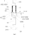
- the suspension engagement portion 1563 extends along the circumferential direction of the body portion 1562, and the outer diameter of the suspension engagement portion 1563 is larger than the outer diameter of the body portion 1562.
- the valve needle support portion 154 is the suspension engagement portion 1563, and the outer diameter of the suspension engagement portion 1563 is larger than the inner diameter of the matching portion 121.
- the distance between D1-D2 may be between 0-0.03mm.
- the washer portion 13 provided on the screw rod 151 abuts against the upper surface of the matching portion 121 of the valve needle sleeve 12, and the valve needle 11 is loaded by the elastic force generated by the spring 14 that is further compressed.
- the electronic expansion valve is in a fully closed state, the screw rod 151 is at the lowest end position of its stroke, and the downward stroke of the screw rod 151 from the fully open state to the fully closed state is L+ ⁇ .
- the spring 14 is mounted around the screw rod 151, and the upper end of the spring 14 abuts against the upper stop portion 155, and the lower end of the spring 14 abuts against the lower stop portion 153.
- the cooperation of the spring 14 and the screw rod assembly 15 may relatively reduce the deflection of the spring 14, thereby reducing eccentric wear.
- the lower stop portion 153 in this embodiment is no longer a lower flange portion 1531.
- the lower stop portion 153 is the body portion 1562 of the bushing part 156. That is, in this embodiment, the body portion 1562 and the washer portion 13 may abut against each other.
- the "may” mentioned in the present application refers to a specific state, but does not mean that the electronic expansion valve is in all working states.
- the body portion 1562 may abut against the washer portion 13, which means that the valve port 211 is fully opened or the like.
- the distance between D1-D2 may be between 0-0.03mm.
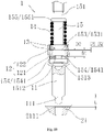
- FIG. 10 is a partial cross-sectional view of the third embodiment of the electronic expansion valve provided by the present application in a fully open state.
- valve needle support portion 154 is a valve needle support washer 1541, and the upper surface of the valve needle support washer 1541 may abut against the matching portion 121 of the valve needle sleeve 12.
- the valve needle 11 may be supported by the valve needle support washer 1541 via the valve needle sleeve 12 fixedly connected to it.
- the "may” mentioned in the present application refers to a specific state, but does not mean that the electronic expansion valve is in all states.
- the matching portion 121 and the valve needle support washer 1541 may abut against each other, which means that the valve port 211 is fully opened or the like.
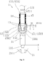
- the screw rod assembly 15 includes an upper stop portion 155, and the upper stop portion 155 abuts against the spring 14.
- the screw rod assembly 15 is equipped with an upper retaining ring 1552.
- the screw rod 151 is further provided with an annular groove 1514 above the spring.
- the annular groove 1514 above the spring is formed by the recessing of the surface of the screw rod 151.
- the upper retaining ring 1552 is assembled in the annular groove 1514 above the spring.
- the upper retaining ring 1552 is fixedly connected, or connected with the annular groove 1514 above the spring with the position thereof is limited, that is, it is clamped into the annular groove 1514 above the spring for being limited. It is also possible to provide the upper flange portion 1551 and the upper retaining ring 1552 at the same time.
- the spring 14 directly abuts the upper retaining ring 1552.
- the spring 14 abuts against the upper flange portion 1551 indirectly.
- the upper stop portion 155 is no longer an upper flange portion 1551, and the upper stop portion 155 is an upper retaining ring 1552. That is, in this embodiment, the upper retaining ring 1552 abuts against the spring 14.
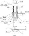
- FIG. 12 is a partial cross-sectional view of the fifth embodiment of the electronic expansion valve provided by the present application in a fully open state.
- valve needle support portion 154 is a sleeve washer 157, and the upper surface of the sleeve washer 157 and the lower surface of the matching portion 121 of the valve needle sleeve 12 may abut against each other.
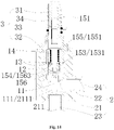
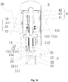
- FIG. 14 is a partial cross-sectional view of the seventh embodiment of the electronic expansion valve provided by the present application in a fully open state;
- valve seat assembly 2 is assembled and fixedly connected by the valve seat 21, the first connecting pipe portion 22 and the second connecting pipe portion 23.
- the center inner hole of the valve seat 21 of the valve seat assembly 2 is provided with an inner hole guide portion 212 that matches with the valve needle screw rod assembly 1.
- the inner hole guide portion 212 of the valve seat 21 provides a guiding function for the valve needle screw rod assembly 1.
- the inner hole guide portion 212 of the valve seat 21 cooperates with the outer edge of the valve needle 11 and/or the peripheral wall portion 122 of the valve needle sleeve 12 to provide guidance for the valve needle screw rod assembly 1.
Landscapes
- Engineering & Computer Science (AREA)
- General Engineering & Computer Science (AREA)
- Mechanical Engineering (AREA)
- Physics & Mathematics (AREA)
- Thermal Sciences (AREA)
- Lift Valve (AREA)
- Electrically Driven Valve-Operating Means (AREA)
Applications Claiming Priority (2)
| Application Number | Priority Date | Filing Date | Title |
|---|---|---|---|
| CN201910575526 | 2019-06-28 | ||
| PCT/CN2020/098381 WO2020259657A1 (fr) | 2019-06-28 | 2020-06-28 | Soupape d'expansion électronique |
Publications (2)
| Publication Number | Publication Date |
|---|---|
| EP3992500A1 true EP3992500A1 (fr) | 2022-05-04 |
| EP3992500A4 EP3992500A4 (fr) | 2023-07-19 |
Family
ID=74060725
Family Applications (1)
| Application Number | Title | Priority Date | Filing Date |
|---|---|---|---|
| EP20832134.9A Pending EP3992500A4 (fr) | 2019-06-28 | 2020-06-28 | Soupape d'expansion électronique |
Country Status (6)
| Country | Link |
|---|---|
| US (1) | US12140354B2 (fr) |
| EP (1) | EP3992500A4 (fr) |
| JP (1) | JP7385673B2 (fr) |
| KR (1) | KR102578174B1 (fr) |
| CN (1) | CN113748286B (fr) |
| WO (1) | WO2020259657A1 (fr) |
Families Citing this family (1)
| Publication number | Priority date | Publication date | Assignee | Title |
|---|---|---|---|---|
| CN114352748B (zh) * | 2022-01-26 | 2024-02-20 | 广东威灵电机制造有限公司 | 阀针组件、电子膨胀阀和制冷设备 |
Family Cites Families (27)
| Publication number | Priority date | Publication date | Assignee | Title |
|---|---|---|---|---|
| JP3817071B2 (ja) * | 1998-07-06 | 2006-08-30 | 株式会社鷺宮製作所 | 電動式コントロールバルブ |
| JP2000213660A (ja) * | 1999-01-22 | 2000-08-02 | Samsung Electronics Co Ltd | 冷凍サイクル用電子膨張弁 |
| JP3937029B2 (ja) * | 1999-03-26 | 2007-06-27 | 株式会社鷺宮製作所 | 電動弁 |
| CN100510580C (zh) * | 2004-12-15 | 2009-07-08 | 株式会社鹭宫制作所 | 电动式控制阀 |
| JP4842692B2 (ja) | 2006-04-21 | 2011-12-21 | 株式会社鷺宮製作所 | アンモニア冷媒冷凍サイクル装置用弁装置およびアンモニア冷媒冷凍サイクル装置 |
| JP2008267464A (ja) * | 2007-04-18 | 2008-11-06 | Fuji Koki Corp | 電動弁 |
| US7854390B2 (en) | 2008-05-29 | 2010-12-21 | Kabushiki Kaisha Saginomiya Seisakusho | Expansion valve, heat pump type refrigeration cycle apparatus, and air handling unit |
| EP3062004B1 (fr) * | 2009-01-22 | 2017-08-16 | Fujikoki Corporation | Vanne motorisée |
| CN102042416B (zh) | 2009-10-09 | 2012-11-21 | 浙江三花股份有限公司 | 电子膨胀阀 |
| US9689595B2 (en) | 2012-05-18 | 2017-06-27 | Zhejiang Sanhua Intelligent Controls Co., Ltd. | Electronic expansion valve |
| CN103512288B (zh) * | 2012-06-20 | 2016-07-06 | 浙江三花股份有限公司 | 一种电子膨胀阀 |
| US9541315B2 (en) * | 2012-08-10 | 2017-01-10 | Zhejiang Sanhua Co., Ltd. | Electronic expanding valve |
| WO2015163242A1 (fr) * | 2014-04-25 | 2015-10-29 | 日立オートモティブシステムズ株式会社 | Vanne électromagnétique et pompe d'alimentation en carburant haute pression comprenant ladite vanne comme mécanisme de clapet d'aspiration |
| CN105626876A (zh) * | 2014-10-28 | 2016-06-01 | 浙江盾安人工环境股份有限公司 | 电子膨胀阀 |
| JP6476534B2 (ja) * | 2015-04-17 | 2019-03-06 | 株式会社不二越 | 電磁弁 |
| US10024450B2 (en) * | 2015-11-25 | 2018-07-17 | Woodward, Inc. | High speed shutdown device for electric actuator |
| CN107304843A (zh) | 2016-04-18 | 2017-10-31 | 浙江盾安人工环境股份有限公司 | 电子膨胀阀 |
| CN205745625U (zh) | 2016-05-10 | 2016-11-30 | 浙江三花股份有限公司 | 电子膨胀阀 |
| CN107356025B (zh) | 2016-05-10 | 2021-08-10 | 浙江三花智能控制股份有限公司 | 电子膨胀阀 |
| CN108317259B (zh) * | 2017-01-18 | 2020-05-05 | 浙江三花制冷集团有限公司 | 一种电子膨胀阀 |
| CN108361386A (zh) * | 2017-01-26 | 2018-08-03 | 浙江三花智能控制股份有限公司 | 电子膨胀阀 |
| WO2018137636A1 (fr) | 2017-01-26 | 2018-08-02 | 浙江三花智能控制股份有限公司 | Détendeur électronique |
| CN108361385A (zh) | 2017-01-26 | 2018-08-03 | 浙江三花智能控制股份有限公司 | 电子膨胀阀 |
| CN206861006U (zh) | 2017-06-16 | 2018-01-09 | 安徽华海金属有限公司 | 一种电子膨胀阀 |
| CN109425150B (zh) * | 2017-08-30 | 2020-05-15 | 浙江三花智能控制股份有限公司 | 电子膨胀阀及具有其的制冷系统 |
| CN208634406U (zh) * | 2018-08-21 | 2019-03-22 | 浙江三花制冷集团有限公司 | 电子膨胀阀 |
| CN209026210U (zh) * | 2018-10-17 | 2019-06-25 | 浙江盾安禾田金属有限公司 | 电子膨胀阀 |
-
2020
- 2020-06-28 WO PCT/CN2020/098381 patent/WO2020259657A1/fr not_active Ceased
- 2020-06-28 JP JP2021556963A patent/JP7385673B2/ja active Active
- 2020-06-28 KR KR1020217033717A patent/KR102578174B1/ko active Active
- 2020-06-28 CN CN202080013132.1A patent/CN113748286B/zh active Active
- 2020-06-28 EP EP20832134.9A patent/EP3992500A4/fr active Pending
- 2020-06-28 US US17/439,452 patent/US12140354B2/en active Active
Also Published As
| Publication number | Publication date |
|---|---|
| CN113748286B (zh) | 2025-01-14 |
| US20220154984A1 (en) | 2022-05-19 |
| CN113748286A (zh) | 2021-12-03 |
| KR20210137564A (ko) | 2021-11-17 |
| EP3992500A4 (fr) | 2023-07-19 |
| JP7385673B2 (ja) | 2023-11-22 |
| JP2022526510A (ja) | 2022-05-25 |
| US12140354B2 (en) | 2024-11-12 |
| KR102578174B1 (ko) | 2023-09-13 |
| WO2020259657A1 (fr) | 2020-12-30 |
Similar Documents
| Publication | Publication Date | Title |
|---|---|---|
| US11846455B2 (en) | Valve needle assembly and electronic expansion valve having the valve needle assembly | |
| US11906055B2 (en) | Electronic expansion valve | |
| WO2018137636A1 (fr) | Détendeur électronique | |
| US11982477B2 (en) | Electronic expansion valve | |
| US12140354B2 (en) | Electronic expansion valve | |
| EP3611409A1 (fr) | Détendeur électronique | |
| CN113685559B (zh) | 一种电子膨胀阀 | |
| CN112879573A (zh) | 一种电子膨胀阀 | |
| CN114719030B (zh) | 一种电子膨胀阀 | |
| CN214171340U (zh) | 阀针组件、电子膨胀阀和制冷设备 | |
| CN115467981A (zh) | 一种电子膨胀阀 | |
| CN221423609U (zh) | 一种内防撞密封缸筒及驱动气缸 | |
| CN223484587U (zh) | 电子膨胀阀及空调系统 | |
| WO2024022321A1 (fr) | Ensemble arbre et électrovanne | |
| CN119914690A (zh) | 电子膨胀阀丝杆传动机构和电子膨胀阀总成 | |
| CN114673793A (zh) | 一种电子膨胀阀 | |
| CN116336195A (zh) | 电子膨胀阀 |
Legal Events
| Date | Code | Title | Description |
|---|---|---|---|
| STAA | Information on the status of an ep patent application or granted ep patent |
Free format text: STATUS: THE INTERNATIONAL PUBLICATION HAS BEEN MADE |
|
| PUAI | Public reference made under article 153(3) epc to a published international application that has entered the european phase |
Free format text: ORIGINAL CODE: 0009012 |
|
| STAA | Information on the status of an ep patent application or granted ep patent |
Free format text: STATUS: REQUEST FOR EXAMINATION WAS MADE |
|
| 17P | Request for examination filed |
Effective date: 20211013 |
|
| AK | Designated contracting states |
Kind code of ref document: A1 Designated state(s): AL AT BE BG CH CY CZ DE DK EE ES FI FR GB GR HR HU IE IS IT LI LT LU LV MC MK MT NL NO PL PT RO RS SE SI SK SM TR |
|
| DAV | Request for validation of the european patent (deleted) | ||
| DAX | Request for extension of the european patent (deleted) | ||
| A4 | Supplementary search report drawn up and despatched |
Effective date: 20230619 |
|
| RIC1 | Information provided on ipc code assigned before grant |
Ipc: F16K 31/50 20060101ALI20230613BHEP Ipc: F16K 1/38 20060101ALI20230613BHEP Ipc: F16K 1/02 20060101ALI20230613BHEP Ipc: F16K 1/00 20060101AFI20230613BHEP |
|
| STAA | Information on the status of an ep patent application or granted ep patent |
Free format text: STATUS: EXAMINATION IS IN PROGRESS |
|
| 17Q | First examination report despatched |
Effective date: 20250320 |