EP3992548B1 - Échangeur de chaleur et appareil de pompe à chaleur - Google Patents
Échangeur de chaleur et appareil de pompe à chaleur Download PDFInfo
- Publication number
- EP3992548B1 EP3992548B1 EP20831706.5A EP20831706A EP3992548B1 EP 3992548 B1 EP3992548 B1 EP 3992548B1 EP 20831706 A EP20831706 A EP 20831706A EP 3992548 B1 EP3992548 B1 EP 3992548B1
- Authority
- EP
- European Patent Office
- Prior art keywords
- liquid
- refrigerant
- plate
- side member
- header
- Prior art date
- Legal status (The legal status is an assumption and is not a legal conclusion. Google has not performed a legal analysis and makes no representation as to the accuracy of the status listed.)
- Active
Links
Images












Classifications
-
- F—MECHANICAL ENGINEERING; LIGHTING; HEATING; WEAPONS; BLASTING
- F25—REFRIGERATION OR COOLING; COMBINED HEATING AND REFRIGERATION SYSTEMS; HEAT PUMP SYSTEMS; MANUFACTURE OR STORAGE OF ICE; LIQUEFACTION SOLIDIFICATION OF GASES
- F25B—REFRIGERATION MACHINES, PLANTS OR SYSTEMS; COMBINED HEATING AND REFRIGERATION SYSTEMS; HEAT PUMP SYSTEMS
- F25B41/00—Fluid-circulation arrangements
- F25B41/40—Fluid line arrangements
- F25B41/42—Arrangements for diverging or converging flows, e.g. branch lines or junctions
-
- F—MECHANICAL ENGINEERING; LIGHTING; HEATING; WEAPONS; BLASTING
- F25—REFRIGERATION OR COOLING; COMBINED HEATING AND REFRIGERATION SYSTEMS; HEAT PUMP SYSTEMS; MANUFACTURE OR STORAGE OF ICE; LIQUEFACTION SOLIDIFICATION OF GASES
- F25B—REFRIGERATION MACHINES, PLANTS OR SYSTEMS; COMBINED HEATING AND REFRIGERATION SYSTEMS; HEAT PUMP SYSTEMS
- F25B30/00—Heat pumps
- F25B30/02—Heat pumps of the compression type
-
- F—MECHANICAL ENGINEERING; LIGHTING; HEATING; WEAPONS; BLASTING
- F25—REFRIGERATION OR COOLING; COMBINED HEATING AND REFRIGERATION SYSTEMS; HEAT PUMP SYSTEMS; MANUFACTURE OR STORAGE OF ICE; LIQUEFACTION SOLIDIFICATION OF GASES
- F25B—REFRIGERATION MACHINES, PLANTS OR SYSTEMS; COMBINED HEATING AND REFRIGERATION SYSTEMS; HEAT PUMP SYSTEMS
- F25B39/00—Evaporators; Condensers
-
- F—MECHANICAL ENGINEERING; LIGHTING; HEATING; WEAPONS; BLASTING
- F25—REFRIGERATION OR COOLING; COMBINED HEATING AND REFRIGERATION SYSTEMS; HEAT PUMP SYSTEMS; MANUFACTURE OR STORAGE OF ICE; LIQUEFACTION SOLIDIFICATION OF GASES
- F25B—REFRIGERATION MACHINES, PLANTS OR SYSTEMS; COMBINED HEATING AND REFRIGERATION SYSTEMS; HEAT PUMP SYSTEMS
- F25B41/00—Fluid-circulation arrangements
- F25B41/40—Fluid line arrangements
-
- F—MECHANICAL ENGINEERING; LIGHTING; HEATING; WEAPONS; BLASTING
- F28—HEAT EXCHANGE IN GENERAL
- F28D—HEAT-EXCHANGE APPARATUS, NOT PROVIDED FOR IN ANOTHER SUBCLASS, IN WHICH THE HEAT-EXCHANGE MEDIA DO NOT COME INTO DIRECT CONTACT
- F28D1/00—Heat-exchange apparatus having stationary conduit assemblies for one heat-exchange medium only, the media being in contact with different sides of the conduit wall, in which the other heat-exchange medium is a large body of fluid, e.g. domestic or motor car radiators
- F28D1/02—Heat-exchange apparatus having stationary conduit assemblies for one heat-exchange medium only, the media being in contact with different sides of the conduit wall, in which the other heat-exchange medium is a large body of fluid, e.g. domestic or motor car radiators with heat-exchange conduits immersed in the body of fluid
- F28D1/04—Heat-exchange apparatus having stationary conduit assemblies for one heat-exchange medium only, the media being in contact with different sides of the conduit wall, in which the other heat-exchange medium is a large body of fluid, e.g. domestic or motor car radiators with heat-exchange conduits immersed in the body of fluid with tubular conduits
- F28D1/047—Heat-exchange apparatus having stationary conduit assemblies for one heat-exchange medium only, the media being in contact with different sides of the conduit wall, in which the other heat-exchange medium is a large body of fluid, e.g. domestic or motor car radiators with heat-exchange conduits immersed in the body of fluid with tubular conduits the conduits being bent, e.g. in a serpentine or zig-zag
- F28D1/0471—Heat-exchange apparatus having stationary conduit assemblies for one heat-exchange medium only, the media being in contact with different sides of the conduit wall, in which the other heat-exchange medium is a large body of fluid, e.g. domestic or motor car radiators with heat-exchange conduits immersed in the body of fluid with tubular conduits the conduits being bent, e.g. in a serpentine or zig-zag the conduits having a non-circular cross-section
-
- F—MECHANICAL ENGINEERING; LIGHTING; HEATING; WEAPONS; BLASTING
- F28—HEAT EXCHANGE IN GENERAL
- F28D—HEAT-EXCHANGE APPARATUS, NOT PROVIDED FOR IN ANOTHER SUBCLASS, IN WHICH THE HEAT-EXCHANGE MEDIA DO NOT COME INTO DIRECT CONTACT
- F28D1/00—Heat-exchange apparatus having stationary conduit assemblies for one heat-exchange medium only, the media being in contact with different sides of the conduit wall, in which the other heat-exchange medium is a large body of fluid, e.g. domestic or motor car radiators
- F28D1/02—Heat-exchange apparatus having stationary conduit assemblies for one heat-exchange medium only, the media being in contact with different sides of the conduit wall, in which the other heat-exchange medium is a large body of fluid, e.g. domestic or motor car radiators with heat-exchange conduits immersed in the body of fluid
- F28D1/04—Heat-exchange apparatus having stationary conduit assemblies for one heat-exchange medium only, the media being in contact with different sides of the conduit wall, in which the other heat-exchange medium is a large body of fluid, e.g. domestic or motor car radiators with heat-exchange conduits immersed in the body of fluid with tubular conduits
- F28D1/047—Heat-exchange apparatus having stationary conduit assemblies for one heat-exchange medium only, the media being in contact with different sides of the conduit wall, in which the other heat-exchange medium is a large body of fluid, e.g. domestic or motor car radiators with heat-exchange conduits immersed in the body of fluid with tubular conduits the conduits being bent, e.g. in a serpentine or zig-zag
- F28D1/0475—Heat-exchange apparatus having stationary conduit assemblies for one heat-exchange medium only, the media being in contact with different sides of the conduit wall, in which the other heat-exchange medium is a large body of fluid, e.g. domestic or motor car radiators with heat-exchange conduits immersed in the body of fluid with tubular conduits the conduits being bent, e.g. in a serpentine or zig-zag the conduits having a single U-bend
- F28D1/0476—Heat-exchange apparatus having stationary conduit assemblies for one heat-exchange medium only, the media being in contact with different sides of the conduit wall, in which the other heat-exchange medium is a large body of fluid, e.g. domestic or motor car radiators with heat-exchange conduits immersed in the body of fluid with tubular conduits the conduits being bent, e.g. in a serpentine or zig-zag the conduits having a single U-bend the conduits having a non-circular cross-section
-
- F—MECHANICAL ENGINEERING; LIGHTING; HEATING; WEAPONS; BLASTING
- F28—HEAT EXCHANGE IN GENERAL
- F28D—HEAT-EXCHANGE APPARATUS, NOT PROVIDED FOR IN ANOTHER SUBCLASS, IN WHICH THE HEAT-EXCHANGE MEDIA DO NOT COME INTO DIRECT CONTACT
- F28D1/00—Heat-exchange apparatus having stationary conduit assemblies for one heat-exchange medium only, the media being in contact with different sides of the conduit wall, in which the other heat-exchange medium is a large body of fluid, e.g. domestic or motor car radiators
- F28D1/02—Heat-exchange apparatus having stationary conduit assemblies for one heat-exchange medium only, the media being in contact with different sides of the conduit wall, in which the other heat-exchange medium is a large body of fluid, e.g. domestic or motor car radiators with heat-exchange conduits immersed in the body of fluid
- F28D1/04—Heat-exchange apparatus having stationary conduit assemblies for one heat-exchange medium only, the media being in contact with different sides of the conduit wall, in which the other heat-exchange medium is a large body of fluid, e.g. domestic or motor car radiators with heat-exchange conduits immersed in the body of fluid with tubular conduits
- F28D1/053—Heat-exchange apparatus having stationary conduit assemblies for one heat-exchange medium only, the media being in contact with different sides of the conduit wall, in which the other heat-exchange medium is a large body of fluid, e.g. domestic or motor car radiators with heat-exchange conduits immersed in the body of fluid with tubular conduits the conduits being straight
- F28D1/05316—Assemblies of conduits connected to common headers, e.g. core type radiators
- F28D1/05333—Assemblies of conduits connected to common headers, e.g. core type radiators with multiple rows of conduits or with multi-channel conduits
-
- F—MECHANICAL ENGINEERING; LIGHTING; HEATING; WEAPONS; BLASTING
- F28—HEAT EXCHANGE IN GENERAL
- F28D—HEAT-EXCHANGE APPARATUS, NOT PROVIDED FOR IN ANOTHER SUBCLASS, IN WHICH THE HEAT-EXCHANGE MEDIA DO NOT COME INTO DIRECT CONTACT
- F28D1/00—Heat-exchange apparatus having stationary conduit assemblies for one heat-exchange medium only, the media being in contact with different sides of the conduit wall, in which the other heat-exchange medium is a large body of fluid, e.g. domestic or motor car radiators
- F28D1/02—Heat-exchange apparatus having stationary conduit assemblies for one heat-exchange medium only, the media being in contact with different sides of the conduit wall, in which the other heat-exchange medium is a large body of fluid, e.g. domestic or motor car radiators with heat-exchange conduits immersed in the body of fluid
- F28D1/04—Heat-exchange apparatus having stationary conduit assemblies for one heat-exchange medium only, the media being in contact with different sides of the conduit wall, in which the other heat-exchange medium is a large body of fluid, e.g. domestic or motor car radiators with heat-exchange conduits immersed in the body of fluid with tubular conduits
- F28D1/053—Heat-exchange apparatus having stationary conduit assemblies for one heat-exchange medium only, the media being in contact with different sides of the conduit wall, in which the other heat-exchange medium is a large body of fluid, e.g. domestic or motor car radiators with heat-exchange conduits immersed in the body of fluid with tubular conduits the conduits being straight
- F28D1/0535—Heat-exchange apparatus having stationary conduit assemblies for one heat-exchange medium only, the media being in contact with different sides of the conduit wall, in which the other heat-exchange medium is a large body of fluid, e.g. domestic or motor car radiators with heat-exchange conduits immersed in the body of fluid with tubular conduits the conduits being straight the conduits having a non-circular cross-section
- F28D1/05366—Assemblies of conduits connected to common headers, e.g. core type radiators
- F28D1/05383—Assemblies of conduits connected to common headers, e.g. core type radiators with multiple rows of conduits or with multi-channel conduits
-
- F—MECHANICAL ENGINEERING; LIGHTING; HEATING; WEAPONS; BLASTING
- F28—HEAT EXCHANGE IN GENERAL
- F28F—DETAILS OF HEAT-EXCHANGE AND HEAT-TRANSFER APPARATUS, OF GENERAL APPLICATION
- F28F1/00—Tubular elements; Assemblies of tubular elements
- F28F1/02—Tubular elements of cross-section which is non-circular
- F28F1/022—Tubular elements of cross-section which is non-circular with multiple channels
-
- F—MECHANICAL ENGINEERING; LIGHTING; HEATING; WEAPONS; BLASTING
- F28—HEAT EXCHANGE IN GENERAL
- F28F—DETAILS OF HEAT-EXCHANGE AND HEAT-TRANSFER APPARATUS, OF GENERAL APPLICATION
- F28F1/00—Tubular elements; Assemblies of tubular elements
- F28F1/10—Tubular elements and assemblies thereof with means for increasing heat-transfer area, e.g. with fins, with projections, with recesses
- F28F1/12—Tubular elements and assemblies thereof with means for increasing heat-transfer area, e.g. with fins, with projections, with recesses the means being only outside the tubular element
- F28F1/24—Tubular elements and assemblies thereof with means for increasing heat-transfer area, e.g. with fins, with projections, with recesses the means being only outside the tubular element and extending transversely
- F28F1/32—Tubular elements and assemblies thereof with means for increasing heat-transfer area, e.g. with fins, with projections, with recesses the means being only outside the tubular element and extending transversely the means having portions engaging further tubular elements
-
- F—MECHANICAL ENGINEERING; LIGHTING; HEATING; WEAPONS; BLASTING
- F28—HEAT EXCHANGE IN GENERAL
- F28F—DETAILS OF HEAT-EXCHANGE AND HEAT-TRANSFER APPARATUS, OF GENERAL APPLICATION
- F28F9/00—Casings; Header boxes; Auxiliary supports for elements; Auxiliary members within casings
- F28F9/02—Header boxes; End plates
- F28F9/0219—Arrangements for sealing end plates into casing or header box; Header box sub-elements
- F28F9/0221—Header boxes or end plates formed by stacked elements
-
- F—MECHANICAL ENGINEERING; LIGHTING; HEATING; WEAPONS; BLASTING
- F28—HEAT EXCHANGE IN GENERAL
- F28F—DETAILS OF HEAT-EXCHANGE AND HEAT-TRANSFER APPARATUS, OF GENERAL APPLICATION
- F28F9/00—Casings; Header boxes; Auxiliary supports for elements; Auxiliary members within casings
- F28F9/02—Header boxes; End plates
- F28F9/0219—Arrangements for sealing end plates into casing or header box; Header box sub-elements
- F28F9/0224—Header boxes formed by sealing end plates into covers
-
- F—MECHANICAL ENGINEERING; LIGHTING; HEATING; WEAPONS; BLASTING
- F28—HEAT EXCHANGE IN GENERAL
- F28F—DETAILS OF HEAT-EXCHANGE AND HEAT-TRANSFER APPARATUS, OF GENERAL APPLICATION
- F28F9/00—Casings; Header boxes; Auxiliary supports for elements; Auxiliary members within casings
- F28F9/02—Header boxes; End plates
- F28F9/026—Header boxes; End plates with static flow control means, e.g. with means for uniformly distributing heat exchange media into conduits
- F28F9/0265—Header boxes; End plates with static flow control means, e.g. with means for uniformly distributing heat exchange media into conduits by using guiding means or impingement means inside the header box
- F28F9/0268—Header boxes; End plates with static flow control means, e.g. with means for uniformly distributing heat exchange media into conduits by using guiding means or impingement means inside the header box in the form of multiple deflectors for channeling the heat exchange medium
-
- F—MECHANICAL ENGINEERING; LIGHTING; HEATING; WEAPONS; BLASTING
- F28—HEAT EXCHANGE IN GENERAL
- F28F—DETAILS OF HEAT-EXCHANGE AND HEAT-TRANSFER APPARATUS, OF GENERAL APPLICATION
- F28F9/00—Casings; Header boxes; Auxiliary supports for elements; Auxiliary members within casings
- F28F9/02—Header boxes; End plates
- F28F9/026—Header boxes; End plates with static flow control means, e.g. with means for uniformly distributing heat exchange media into conduits
- F28F9/027—Header boxes; End plates with static flow control means, e.g. with means for uniformly distributing heat exchange media into conduits in the form of distribution pipes
- F28F9/0275—Header boxes; End plates with static flow control means, e.g. with means for uniformly distributing heat exchange media into conduits in the form of distribution pipes with multiple branch pipes
-
- F—MECHANICAL ENGINEERING; LIGHTING; HEATING; WEAPONS; BLASTING
- F28—HEAT EXCHANGE IN GENERAL
- F28F—DETAILS OF HEAT-EXCHANGE AND HEAT-TRANSFER APPARATUS, OF GENERAL APPLICATION
- F28F9/00—Casings; Header boxes; Auxiliary supports for elements; Auxiliary members within casings
- F28F9/02—Header boxes; End plates
- F28F9/026—Header boxes; End plates with static flow control means, e.g. with means for uniformly distributing heat exchange media into conduits
- F28F9/0278—Header boxes; End plates with static flow control means, e.g. with means for uniformly distributing heat exchange media into conduits in the form of stacked distribution plates or perforated plates arranged over end plates
-
- F—MECHANICAL ENGINEERING; LIGHTING; HEATING; WEAPONS; BLASTING
- F25—REFRIGERATION OR COOLING; COMBINED HEATING AND REFRIGERATION SYSTEMS; HEAT PUMP SYSTEMS; MANUFACTURE OR STORAGE OF ICE; LIQUEFACTION SOLIDIFICATION OF GASES
- F25B—REFRIGERATION MACHINES, PLANTS OR SYSTEMS; COMBINED HEATING AND REFRIGERATION SYSTEMS; HEAT PUMP SYSTEMS
- F25B13/00—Compression machines, plants or systems, with reversible cycle
-
- F—MECHANICAL ENGINEERING; LIGHTING; HEATING; WEAPONS; BLASTING
- F25—REFRIGERATION OR COOLING; COMBINED HEATING AND REFRIGERATION SYSTEMS; HEAT PUMP SYSTEMS; MANUFACTURE OR STORAGE OF ICE; LIQUEFACTION SOLIDIFICATION OF GASES
- F25B—REFRIGERATION MACHINES, PLANTS OR SYSTEMS; COMBINED HEATING AND REFRIGERATION SYSTEMS; HEAT PUMP SYSTEMS
- F25B49/00—Arrangement or mounting of control or safety devices
- F25B49/02—Arrangement or mounting of control or safety devices for compression type machines, plants or systems
-
- F—MECHANICAL ENGINEERING; LIGHTING; HEATING; WEAPONS; BLASTING
- F28—HEAT EXCHANGE IN GENERAL
- F28D—HEAT-EXCHANGE APPARATUS, NOT PROVIDED FOR IN ANOTHER SUBCLASS, IN WHICH THE HEAT-EXCHANGE MEDIA DO NOT COME INTO DIRECT CONTACT
- F28D21/00—Heat-exchange apparatus not covered by any of the groups F28D1/00 - F28D20/00
- F28D2021/0019—Other heat exchangers for particular applications; Heat exchange systems not otherwise provided for
- F28D2021/0061—Other heat exchangers for particular applications; Heat exchange systems not otherwise provided for for phase-change applications
- F28D2021/0064—Vaporizers, e.g. evaporators
-
- F—MECHANICAL ENGINEERING; LIGHTING; HEATING; WEAPONS; BLASTING
- F28—HEAT EXCHANGE IN GENERAL
- F28D—HEAT-EXCHANGE APPARATUS, NOT PROVIDED FOR IN ANOTHER SUBCLASS, IN WHICH THE HEAT-EXCHANGE MEDIA DO NOT COME INTO DIRECT CONTACT
- F28D21/00—Heat-exchange apparatus not covered by any of the groups F28D1/00 - F28D20/00
- F28D2021/0019—Other heat exchangers for particular applications; Heat exchange systems not otherwise provided for
- F28D2021/0068—Other heat exchangers for particular applications; Heat exchange systems not otherwise provided for for refrigerant cycles
-
- F—MECHANICAL ENGINEERING; LIGHTING; HEATING; WEAPONS; BLASTING
- F28—HEAT EXCHANGE IN GENERAL
- F28F—DETAILS OF HEAT-EXCHANGE AND HEAT-TRANSFER APPARATUS, OF GENERAL APPLICATION
- F28F2215/00—Fins
- F28F2215/12—Fins with U-shaped slots for laterally inserting conduits
Definitions
- the present invention relates to a heat exchanger and a heat pump device.
- JP 2016 070622 A proposes a circular cylindrical header including semi-circular members that abut upon each other.
- a conventional heat exchanger and a conventional heat pump device is also dislosed in WO 2018/116 413 A1 , which forms the basis for the preamble of independent claim 1.
- a similar dislosure may also be found in US 5,252,016 A , US 5,205,347 A , and US 2018/0300758 A1 .
- the nozzles are provided in the header as openings of a plate-shaped member extending perpendicularly to the longitudinal direction of the header.
- An object of the present invention is to provide a heat exchanger and a heat pump device that, with a small number of components, are capable of sending a refrigerant in a direction in which a plurality of heat transfer tubes are disposed side by side, the plurality of heat transfer tubes being connected to a header.
- Fig. 1 is a schematic structural view of the air conditioner 1 including a heat exchanger according to an embodiment of the present invention as an outdoor heat exchanger 11.
- the air conditioner 1 (an example of the heat pump device) is a device that cools and heats a space to be air-conditioned by performing a vapor-compression refrigeration cycle.
- the space to be air-conditioned is, for example, a space in buildings, such as office buildings, commercial facilities, or residences.
- the air conditioner is merely an example of the refrigerant cycle device, and the heat exchanger of the present invention may be used in other refrigerant cycle devices, such as a refrigerator, a freezer, a water heater, or a floor heating device.
- the air conditioner 1 primarily includes an outdoor unit 2, an indoor unit 9, a liquid-refrigerant connection pipe 4 and a gas-refrigerant connection pipe 5, and a control unit 3 that controls devices that constitute the outdoor unit 2 and the indoor unit 9.
- the liquid-refrigerant connection pipe 4 and the gas-refrigerant connection pipe 5 are refrigerant connection pipes that connect the outdoor unit 2 and the indoor unit 9 to each other.
- the outdoor unit 2 and the indoor unit 9 are connected to each other via the liquid-refrigerant connection pipe 4 and the gas-refrigerant connection pipe 5 to constitute a refrigerant circuit 6.
- the air conditioner 1 includes one indoor unit 9, the air conditioner 1 may include a plurality of indoor units 9 that are connected side by side to the outdoor unit 2 by the liquid-refrigerant connection pipe 4 and the gas-refrigerant connection pipe 5.
- the air conditioner 1 may also include a plurality of outdoor units 2.
- the air conditioner 1 may be an integrated air conditioner in which the outdoor unit 2 and the indoor unit 9 are integrated with each other.
- the outdoor unit 2 is installed outside a space to be air-conditioned, such as on the roof of a building or near a wall surface of a building.
- the outdoor unit 2 primarily includes an accumulator 7, a compressor 8, a four-way switching valve 10, the outdoor heat exchanger 11, an expansion mechanism 12, a liquid-side shutoff valve 13 and a gas-side shutoff valve 14, and an outdoor fan 16 (see Fig. 1 ).
- the outdoor unit 2 primarily includes, as refrigerant pipes that connect various devices constituting the refrigerant circuit 6, a suction pipe 17, a discharge pipe 18, a first gas-refrigerant pipe 19, a liquid refrigerant pipe 20, and a second gas-refrigerant pipe 21 (see Fig. 1 ).
- the suction pipe 17 connects the four-way switching valve 10 and a suction side of the compressor 8.
- the accumulator 7 is provided at the suction pipe 17.
- the discharge pipe 18 connects a discharge side of the compressor 8 and the four-way switching valve 10 to each other.
- the first gas-refrigerant pipe 19 connects the four-way switching valve 10 and a gas side of the outdoor heat exchanger 11 to each other.
- the liquid refrigerant pipe 20 connects a liquid side of the outdoor heat exchanger 11 and the liquid-side shutoff valve 13 to each other.
- the expansion mechanism 12 is provided at the liquid refrigerant pipe 20.
- the second gas-refrigerant pipe 21 connects the four-way switching valve 10 and the gas-side shutoff valve 14 to each other.
- the compressor 8 is a device that sucks in a refrigerant having a low pressure in a refrigeration cycle from the suction pipe 17, compresses the refrigerant at a compression mechanism (not shown), and discharges the compressed refrigerant to the discharge pipe 18.
- the four-way switching valve 10 is a mechanism that, by switching a direction of flow of a refrigerant, changes the state of the refrigerant circuit 6 between a cooling operation state and a heating operation state.
- the outdoor heat exchanger 11 functions as a heat dissipater (condenser) of a refrigerant and an indoor heat exchanger 91 functions as an evaporator of a refrigerant.
- the outdoor heat exchanger 11 functions as an evaporator of a refrigerant
- the indoor heat exchanger 91 functions as a condenser of a refrigerant.
- the four-way switching valve 10 When the four-way switching valve 10 changes the state of the refrigerant circuit 6 to the cooling operation state, the four-way switching valve 10 causes the suction pipe 17 to communicate with the second gas-refrigerant pipe 21, and causes the discharge pipe 18 to communicate with the first gas-refrigerant pipe 19 (see solid line in the four-way switching valve 10 in Fig. 1 ).
- the four-way switching valve 10 changes the state of the refrigerant circuit 6 to the heating operation state
- the four-way switching valve 10 causes the suction pipe 17 to communicate with the first gas-refrigerant pipe 19, and causes the discharge pipe 18 to communicate with the second gas-refrigerant pipe 21 (see broken line in the four-way switching valve 10 in Fig. 1 ).
- the outdoor heat exchanger 11 (an example of the heat exchanger) is a device that causes a refrigerant that flows therein and air existing at a place of installation of the outdoor unit 2 (heat source air) to exchange heat with each other.
- the outdoor heat exchanger 11 is described in detail below.
- the expansion mechanism 12 is disposed between the outdoor heat exchanger 11 and the indoor heat exchanger 91 in the refrigerant circuit 6.
- the expansion mechanism 12 is disposed at the liquid refrigerant pipe 20 between the outdoor heat exchanger 11 and the liquid-side shutoff valve 13.
- the expansion mechanism 12 is a mechanism that adjusts the pressure and the flow rate of a refrigerant that flows in the liquid refrigerant pipe 20.
- the expansion mechanism 12 is an electronic expansion valve whose opening degree is variable, the expansion mechanism 12 may be a temperature-sensitive cylinder expansion valve or capillary tube.
- the accumulator 7 is a container having a gas-liquid dividing function of dividing an inflowing refrigerant into a gas refrigerant and a liquid refrigerant.
- the accumulator 7 is also a container having the function of storing excess refrigerant produced in according with, for example, variations in an operation load.
- the liquid-side shutoff valve 13 is a valve that is provided at a connection portion between the liquid refrigerant pipe 20 and the liquid-refrigerant connection pipe 4.
- the gas-side shutoff valve 14 is a valve that is provided at a connection portion between the second gas-refrigerant pipe 21 and the gas-refrigerant connection pipe 5.
- the liquid-side shutoff valve 13 and the gas-side shutoff valve 14 are open when the air conditioner 1 operates.
- the outdoor fan 16 (an example of the fan) is a fan for sucking in external heat source air into a casing of the outdoor unit 2 (not shown), supplying the air to the outdoor heat exchanger 11, and discharging the air that has exchanged heat with a refrigerant in the outdoor heat exchanger 11 to the outside of the casing of the outdoor unit 2.
- the outdoor fan 16 is, for example, a propeller fan.
- the indoor unit 9 is a unit that is installed in a space to be air-conditioned.
- the indoor unit 9 is, for example, a ceiling-embedded unit
- the indoor unit 9 may be a ceiling-suspension unit, a wall-mounted unit, or a floor unit.
- the indoor unit 9 may be installed outside a space to be air-conditioned.
- the indoor unit 9 may be installed in an attic, a machine chamber, or a garage.
- an air passage that supplies air that has exchanged heat with a refrigerant in the indoor heat exchanger 91 to a space to be air-conditioned from the indoor unit 9 is provided.
- the air passage is, for example, a duct.
- the indoor unit 9 primarily includes the indoor heat exchanger 91 and an indoor fan 92 (see Fig. 1 ).
- the indoor heat exchanger 91 a refrigerant that flows in the indoor heat exchanger 91 and air in a space to be air-conditioned exchanges heat with each other.
- the indoor heat exchanger 91 is, for example, a fin-and-tube heat exchanger including a plurality of heat transfer tubes and fins that are not shown.
- One end of the indoor heat exchanger 91 is connected to the liquid-refrigerant connection pipe 4 via a refrigerant pipe.
- the other end of the indoor heat exchanger 91 is connected to the gas-refrigerant connection pipe 5 via a refrigerant pipe.
- the indoor fan 92 is a mechanism that sucks in air in a space to be air-conditioned into a casing (not shown) of the indoor unit 9, supplies the air to the indoor heat exchanger 91, and blows out the air that has exchanged heat with a refrigerant in the indoor heat exchanger 91 to the space to be air-conditioned.
- the indoor fan 92 is, for example, a turbo fan.
- the type of indoor fan 92 is not limited to a turbo fan, and may be selected as appropriate.
- the control unit 3 is a functional part that controls the operations of various devices that form the air conditioner 1.
- the control unit 3 is constituted by, for example, connecting an outdoor control unit (not shown) of the outdoor unit 2 and an indoor control unit (not shown) of the indoor unit 9 via a transmission line (not shown) to allow communication.
- the outdoor control unit and the indoor control unit are, for example, a microcomputer or a unit including, for example, a memory that stores various programs for controlling the air conditioner 1, which are executable by the microcomputer.
- Fig. 1 illustrates the control unit 3 at a position situated away from the outdoor unit 2 and the indoor unit 9.
- control unit 3 do not need to be realized by cooperation between the outdoor control unit and the indoor control unit.
- the functions of the control unit 3 may be realized by either one of the outdoor control unit and the indoor control unit, or some or all of the functions of the control unit 3 may be realized by a control device (not shown) that differs from the outdoor control unit and the indoor control unit.
- control unit 3 is electrically connected to the various devices of the outdoor unit 2 and the indoor unit 9, including the compressor 8, the four-way switching valve 10, the expansion mechanism 12, the outdoor fan 16, and the indoor fan 92.
- the control unit 3 is also electrically connected to various sensors (not shown) that are provided at the outdoor unit 2 and the indoor unit 9.
- the control unit 3 is constituted to allow communication with a remote controller (not shown) that is operated by a user of the air conditioner 1.
- the control unit 3 controls the operation and stopping of the air conditioner 1 or the operations of the various devices that constitute the air conditioner 1, based on, for example, a measurement signal of each of the various sensors or an instruction that is received from a remote controller (not shown).
- Fig. 2 is a schematic perspective view of the outdoor heat exchanger 11.
- Fig. 3 is an enlarged view of a portion of a heat exchange portion 27 (described below) of the outdoor heat exchanger 11.
- Fig. 4 is a schematic view showing fins 29 (described below) mounted on flat tubes 28 in the heat exchange portion 27.
- Fig. 5 is a schematic structural view of the outdoor heat exchanger 11. The arrows in the heat exchange portion 27 shown in Fig. 5 indicate flow of a refrigerant at the time of a heating operation (when the outdoor heat exchanger 11 functions as an evaporator).
- the outdoor heat exchanger 11 is a device that causes heat to be exchanged between a refrigerant that flows therein and air.
- the outdoor heat exchanger 11 primarily includes a distributor 22, a flat tube group 28G including the plurality of flat tubes 28, the plurality of fins 29, a liquid header 30 (an example of the header), and a gas header 70 (see Figs. 4 and 5 ).
- the distributor 22, the flat tubes 28, the fins 29, the liquid header 30, and the gas header 70 are all made of aluminum or an aluminum alloy.
- the outdoor heat exchanger 11 is a device including the one-column heat exchange portion 27, and is not a device in which the plurality of flat tubes 28 are disposed side by side in an air flow direction.
- a refrigerant that flows in the flat tubes 28 exchanges heat with the air that flows in the ventilation path.
- the heat exchange portion 27 is divided into a first heat exchange portion 27a, a second heat exchange portion 27b, a third heat exchange portion 27c, a fourth heat exchange portion 27d, and a fifth heat exchange portion 27e, which are disposed side by side in an up-down direction (see Fig. 2 ).
- the distributor 22 is a mechanism that divides a flow of a refrigerant.
- the distributor 22 is also a mechanism that merges refrigerants.
- the liquid refrigerant pipe 20 is connected to the distributor 22.
- the distributor 22 includes a plurality of flow dividing pipes 22a to 22e.
- the distributor 22 has the function of dividing a flow of a refrigerant that has flowed into the distributor 22 from the liquid refrigerant pipe 20 by the plurality of flow dividing pipes 22a to 22e (an example of refrigerant pipes) and of guiding the separated portions of the refrigerant to a plurality of spaces that are formed in the liquid header 30.
- the distributor 22 also has the function of merging the portions of the refrigerant that have flowed through the flow dividing pipes 22a to 22e from the liquid header 30 and of guiding the merged portions of the refrigerant to the liquid refrigerant pipe 20. Specifically, the flow dividing pipes 22a to 22e and the plurality of spaces in the liquid header 30 are connected to each other via a corresponding one of branch liquid-refrigerant connection pipes 49a to 49e.
- the flat tube group 28G is an example of a heat transfer tube group.
- the flat tube group 28G includes the plurality of flat tubes 28 as a plurality of heat transfer tubes.
- the flat tubes 28 are flat heat transfer tubes having a flat surface 28a, which is a heat transfer surface, in the up-down direction.
- the flat tubes 28 have a plurality of refrigerant passages 28b in which a refrigerant flows.
- the flat tubes 28 are flat multi-hole tubes where many refrigerant passages 28b in which a refrigerant flows and whose passage cross-sectional area is small are formed.
- the plurality of refrigerant passages 28b are provided side by side in an air flow direction.
- the maximum width of a cross section of the flat tubes 28 perpendicular to the refrigerant passages 28b may be greater than or equal to 70% or greater than or equal to 85% of the outside diameter of a main gas-refrigerant-pipe connection portion 19a.
- the flat tubes 28 extending in a horizontal direction between the liquid header 30 and the gas header 70 are disposed side by side in an up-down direction in a plurality of layers.
- the flat tubes 28 extending between the liquid header 30 and the gas header 70 are bent at two locations, and the heat exchange portion 27 that is constituted by the flat tubes 28 is formed in a substantially U shape in plan view (see Fig. 2 ).
- the plurality of flat tubes 28 are disposed apart from each other by a certain interval in the up-down direction.
- the plurality of fins 29 are members for increasing the heat transfer area of the outdoor heat exchanger 11.
- Each fin 29 is a plate-shaped member extending in a direction in which the flat tubes 28 are disposed side by side in layers.
- the outdoor heat exchanger 11 is used in a mode in which the plurality of flat tubes 28 extending in the horizontal direction are disposed side by side in the up-down direction. Therefore, with the outdoor heat exchanger 11 being installed at the outdoor unit 2, each fin 29 extends in the up-down direction.
- a plurality of cut portions 29a extending in an insertion direction of the flat tubes 28 are formed in each fin 29 to allow the plurality of flat tubes 28 to be inserted therein.
- the cut portions 29a extend in the direction of extension of the fins 29 and in a direction orthogonal to a thickness direction of the fins 29. With the outdoor heat exchanger 11 being installed at the outdoor unit 2, the cut portions 29a in each fin 29 extend in the horizontal direction.
- the shape of the cut portions 29a of the fins 29 is substantially the same as the external shape of the cross section of the flat tubes 28.
- the cut portions 29a are formed in the fins 29 to be apart from each other by an interval corresponding to an arrangement interval of the flat tubes 28.
- the plurality of fins 29 are disposed side by side in the direction of extension of the flat tubes 28.
- Each fin 29 includes communication portions 29b communicating with each other in the up-down direction on an upstream side or a downstream side of the air flow direction with respect to the flat tubes 28.
- the communication portions 29b of the fins 29 are positioned on a windward side with respect to the flat tubes 28.
- the gas header 70 and the liquid header 30 are hollow members.
- each flat tube 28 is connected to the liquid header 30, and the other end portion of each flat tube 28 is connected to the gas header 70.
- the outdoor heat exchanger 11 is disposed in the casing (not shown) of the outdoor unit 2 so that longitudinal directions of the liquid header 30 and the gas header 70 are substantially the same as a vertical direction (an example of the second direction).
- the heat exchange portion 27 of the outdoor heat exchanger 11 has a U shape in plan view.
- the liquid header 30 is disposed near a left front corner of the casing (not shown) of the outdoor unit 2 (see Fig. 2 ).
- the gas header 70 is disposed near a right front corner of the casing (not shown) of the outdoor unit 2 (see Fig. 2 ).
- the main gas-refrigerant-pipe connection portion 19a and a branch gas-refrigerant-pipe connection portion 19b that constitute an end portion of the first gas-refrigerant pipe 19 on the side of the gas header 70 are connected to the gas header 70 (see Fig. 5 ).
- the outside diameter of the main gas-refrigerant-pipe connection portion 19a may be, for example, greater than or equal to three times, or greater than or equal to five times the outside diameter of the branch gas-refrigerant-pipe connection portion 19b.
- One end of the main gas-refrigerant-pipe connection portion 19a is connected to the gas header 70 to communicate with a gas-side internal space 25 at an intermediate position on the gas header 70 in a height direction.
- branch gas-refrigerant-pipe connection portion 19b One end of the branch gas-refrigerant-pipe connection portion 19b is connected to the gas header 70 to communicate with the gas-side internal space 25 near a lower end of the gas header 70 in the height direction.
- the other end of the branch gas-refrigerant-pipe connection portion 19b is connected to the main gas-refrigerant-pipe connection portion 19a.
- the branch gas-refrigerant-pipe connection portion 19b is capable of bringing refrigerating-machine oil that is retained near the lower end of the gas header 70 into the main gas-refrigerant-pipe connection portion 19a and returning the refrigerating-machine oil to the compressor 8.
- a liquid-side internal space 23 of the liquid header 30 is divided into a plurality of sub-spaces 23a to 23e (see Fig. 5 ).
- the plurality of sub-spaces 23a to 23e are disposed side by side in the up-down direction. Each of the sub-spaces 23a to 23e do not communicate with each other in the liquid-side internal space 23 of the liquid header 30.
- the branch liquid-refrigerant connection pipes 49a to 49e (an example of liquid refrigerant pipes) connected to the respective flow dividing pipes 22a to 22e of the distributor22 are connected in a one-to-one correspondence with the respective sub-spaces 23a to 23e. Therefore, in a cooling operation state, portions of a refrigerant that have reached the respective sub-spaces 23a to 23e flow into the respective branch liquid-refrigerant connection pipes 49a to 49e and the respective flow dividing pipes 22a to 22e, and merge at the distributor 22.
- a refrigerant whose flow has been divided at the distributor22 flows into each of the flow dividing pipes 22a to 22e and each of the branch liquid-refrigerant connection pipes 49a to 49e, and is supplied to each of the sub-spaces 23a to 23e.
- a refrigerant in a gas-liquid two-phase state that has reached the distributor 22 from the liquid refrigerant pipe 20 flows through the flow dividing pipes 22a to 22e and flows into each of the sub-spaces 23a to 23e that constitute the liquid-side internal space 23 of the liquid header 30.
- a portion of the refrigerant that has flowed in the flow dividing pipe 22a flows to the sub-space 23a
- a portion of the refrigerant that has flowed in the flow dividing pipe 22b flows to the sub-space 23b
- a portion of the refrigerant that has flowed in the flow dividing pipe 22c flows to the sub-space 23c
- a portion of the refrigerant that has flowed in the flow dividing pipe 22d flows to the sub-space 23d
- a portion of the refrigerant that has flowed in the flow dividing pipe 22e flows to the sub-space 23e.
- the portions of the refrigerant that have flowed into the respective sub-spaces 23a to 23e of the liquid-side internal space 23 flow to the respective flat tubes 28 connected to the respective sub-spaces 23a to 23e.
- the portions of the refrigerant flowing in the respective flat tubes 28 exchange heat with air and thus evaporate and become portions of a gas-phase refrigerant, and flow into the gas-side internal space 25 of the gas header 70 to merge with each other.
- a refrigerant flows in the refrigerant circuit 6 in a direction opposite to that when the air conditioner 1 performs the heating operation. Specifically, a high-temperature gas-phase refrigerant flows into the gas-side internal space 25 of the gas header 70 via the main gas-refrigerant-pipe connection portion 19a and the branch gas-refrigerant-pipe connection portion 19b of the first gas-refrigerant pipe 19.
- the refrigerant that has flowed into the gas-side internal space 25 of the gas header 70 is divided by and flows into each flat tube 28.
- Portions of the refrigerant that have flowed into the respective flat tubes 28 pass through the respective flat tubes 28, and flow into the sub-spaces 23a to 23e of the liquid-side internal space 23 of the liquid header 30.
- the portions of the refrigerant that have flowed into the sub-spaces 23a to 23e of the liquid-side internal space 23 merge at the distributor 22 and flow out of the liquid refrigerant pipe 20.
- Fig. 6 is a side external structural view showing a state of connection of the branch liquid-refrigerant connection pipes 49a to 49e with the liquid header 30.
- Fig. 7 is an exploded perspective view of the liquid header 30 (note that, in this figure, alternate-long-and-two-short-dash-line arrows indicate the flow of a refrigerant when the outdoor heat exchanger 11 functions as an evaporator of the refrigerant).
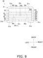
- Fig. 8 is a plan sectional view of the liquid header 30.
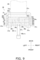
- Fig. 9 is a plan sectional view showing a state of connection of the branch liquid-refrigerant connection pipes 49a to 49e and the flat tubes 28 with the liquid header 30.
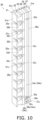
- Fig. 10 is a sectional perspective view of a portion of the liquid header 30 near an upper end thereof.
- Fig. 11 is a back schematic view of a first liquid-side member 31.
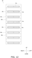
- Fig. 12 is a back schematic view of a second liquid-side member 32.
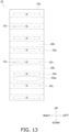
- Fig. 13 is a back schematic view of a third liquid-side member 33.
- Fig. 14 is a back schematic view of a fourth liquid-side member 34.
- Fig. 15 is a back schematic view of a fifth liquid-side member 35.
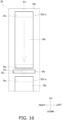
- Fig. 16 is a back schematic view of a sixth liquid-side member 36.
- Fig. 17 is a back schematic view of a seventh liquid-side member 37. Note that each of these figures show with, for example, broken lines, the relationships between the positions of openings of the members that are disposed adjacent to each other while projecting them.
- the liquid header 30 includes the first liquid-side member 31, the second liquid-side member 32, the third liquid-side member 33, the fourth liquid-side member 34, the fifth liquid-side member 35, the sixth liquid-side member 36, and the seventh liquid-side member 37.
- the liquid header 30 is constituted by joining the first liquid-side member 31, the second liquid-side member 32, the third liquid-side member 33, the fourth liquid-side member 34, the fifth liquid-side member 35, the sixth liquid-side member 36, and the seventh liquid-side member 37 to each other by brazing.
- first liquid-side member 31, the third liquid-side member 33, the fourth liquid-side member 34, the fifth liquid-side member 35, the sixth liquid-side member 36, and the seventh liquid-side member 37 be constituted to have a plate thickness of 3 mm or less. It is desirable that the first liquid-side member 31, the second liquid-side member 32, the third liquid-side member 33, the fourth liquid-side member 34, the fifth liquid-side member 35, the sixth liquid-side member 36, and the seventh liquid-side member 37 each be a member having a thickness in a plate-thickness direction that is shorter than a length in a vertical direction and that is shorter than a length in a left-right direction.
- the first liquid-side member 31, the third liquid-side member 33, the fourth liquid-side member 34, the fifth liquid-side member 35, the sixth liquid-side member 36, and the seventh liquid-side member 37 are stacked in a stacking direction (an example of the first direction), which is the plate-thickness direction.
- the liquid header 30 has a substantially quadrilateral shape having a connection portion with the flat tubes 28 as one side.
- the first liquid-side member 31 is primarily a member that, together with the seventh liquid-side member 37 described below, constitutes the periphery of the external shape of the liquid header 30. It is desirable that the first liquid-side member 31 have a clad layer formed on a surface thereof, the clad layer having a brazing material.
- the first liquid-side member 31 includes a liquid-side flat-tube connection plate 31a (an example of the first plate-shaped portion), a first liquid-side outer wall 31b, a second liquid-side outer wall 31c, a first liquid-side claw portion 31d, and a second liquid-side claw portion 31e.
- the first liquid-side member 31 of the present embodiment can be formed by bending one metal plate obtained by rolling with the longitudinal direction of the liquid header 30 being a direction of fold. In this case, the plate thickness of each portion of the first liquid-side member 31 is uniform.
- the liquid-side flat-tube connection plate 31a is a flat-shaped portion extending in the up-down direction and in the left-right direction.
- a plurality of liquid-side flat-tube connection openings 31x disposed side by side in the up-down direction are formed in the liquid-side flat-tube connection plate 31a.
- Each liquid-side flat-tube connection opening 31x is a through opening in the thickness direction of the liquid-side flat-tube connection plate 31a.
- each liquid-side flat-tube connection opening 31x and the entire outer peripheral surface of each flat tube 28 are in contact with each other.
- the thickness of the first liquid-side member 31 including the liquid-side flat-tube connection plate 31a is relatively small, such as on the order of 1.0 mm or greater and 2.0 mm or less, the length of the inner peripheral surface of each liquid-side flat-tube connection opening 31x in the plate-thickness direction can be short.
- the first liquid-side outer wall 31b is a flat-shaped portion extending toward a front side from a front surface of an end portion on a left side (outer side of the outdoor unit 2, side opposite to the gas header 70) of the liquid-side flat-tube connection plate 31a.
- the second liquid-side outer wall 31c is a flat-shaped portion extending toward the front side from a front surface of an end portion on a right side (inner side of the outdoor unit 2, side of the gas header 70) of the liquid-side flat-tube connection plate 31a.
- the first liquid-side claw portion 31d is a portion extending toward the right from a front end portion of the first liquid-side outer wall 31b.
- the second liquid-side claw portion 31e is a portion extending toward the left from a front end portion of the second liquid-side outer wall 31c.
- the first liquid-side claw portion 31d and the second liquid-side claw portion 31e are each in an extended state on an extension line of a corresponding one of the first liquid-side outer wall 31b and the second liquid-side outer wall 31c.
- the first liquid-side claw portion 31d and the second liquid-side claw portion 31e are bent toward each other to crimp the second liquid-side member 32, the third liquid-side member 33, the fourth liquid-side member 34, the fifth liquid-side member 35, the sixth liquid-side member 36, and the seventh liquid-side member 37 by the first liquid-side member 31, as a result of which they are fixed to each other.
- brazing is performed, for example, inside a furnace, the members are joined to each other by brazing and are completely fixed to each other.
- the second liquid-side member 32 includes a plate-shaped base portion 32a and a plurality of protrusions 32b that protrude toward the liquid-side flat-tube connection plate 31a from the base portion 32a.
- the second liquid-side member 32 may not have a clad layer formed on a surface thereof, the clad layer having a brazing material.
- the base portion 32a extends parallel to the liquid-side flat-tube connection plate 31a and has a plate shape in which the direction of extension of the flat tubes 28 is the plate-thickness direction.
- the width of the base portion 32a in the left-right direction is the same as the width of a portion of the liquid-side flat-tube connection plate 31a in the left-right direction excluding the two end portions.
- a plurality of communication holes 32x provided side by side in the up-down direction are formed in a one-to-one correspondence with the flat tubes 28 at positions in the base portion 32a other than the positions where the protrusions 32b are provided. When viewed from the back, the communication holes 32x have shapes that are substantially the same as those of the end portions of the flat tubes 28.
- the protrusions 32b extend in the horizontal direction up to where they come into contact with a front surface of the liquid-side flat-tube connection plate 31a by extending toward the back from portions of the base portion 32a between the communication holes 32x adjacent to each other. Therefore, there are formed insertion spaces 32s surrounded by the front surface of the liquid-side flat-tube connection plate 31a of the first liquid-side member 31, the first liquid-side outer wall 31b and the second liquid-side outer wall 31c of the first liquid-side member 31, the protrusions 32b that are adjacent to each other in the up-down direction of the second liquid-side member 32, and portions of a back surface of the base portion 32a of the second liquid-side member 32 other than the communication holes 32x.
- the insertion spaces 32s are provided side by side in the longitudinal direction of the liquid header 30.
- An end portion of each flat tube 28 is positioned in each insertion space 32s. Note that the lengths of the protrusions 32b in the front-back direction are adjusted to be larger than the plate thickness of any one of the first liquid-side member 31, the third liquid-side member 33, the fourth liquid-side member 34, the fifth liquid-side member 35, the sixth liquid-side member 36, and the seventh liquid-side member 37 that constitute the liquid header 30.
- the third liquid-side member 33 is a member that is stacked on a surface on a front side (side at which the branch liquid-refrigerant connection pipes 49a to 49e and the liquid header 30 are connected to each other) of the base portion 32a of the second liquid-side member 32 so as to face and contact this surface.
- the length of the third liquid-side member 33 in the left-right direction is the same as the length of the second liquid-side member 32 in the left-right direction. It is desirable that the third liquid-side member 33 have a clad layer formed on a surface thereof, the clad layer having a brazing material.
- the third liquid-side member 33 (an example of the sixth member) includes a third internal plate 33a (an example of the sixth plate-shaped portion) and a plurality of flow dividing openings 33x (an example of the fifth openings).
- the third internal plate 33a has a flat shape extending in the up-down direction and in the left-right direction.
- the plurality of flow dividing openings 33x are disposed side by side in the up-down direction, and are through openings in the plate-thickness direction of the third internal plate 33a.
- each flow dividing opening 33x is formed near the center of the third internal plate 33a in the left-right direction. When viewed from the back, each flow dividing opening 33x overlaps a corresponding one of the communication holes 32x of the second liquid-side member 32 and communicates with each other.
- a refrigerant that flows in an ascending space 34z (described below) can be branched toward each of the flow dividing openings 33x and caused to flow, and the refrigerant can be divided with respect to each flat tube 28 connected to a corresponding one of the flow dividing openings 33x.
- a front surface of the third internal plate 33a a surface thereof other than where the flow dividing openings 33x are formed forms the contour of the ascending space 34z (described below).
- the fourth liquid-side member 34 is a member that is stacked on a surface on a front side (side at which the branch liquid-refrigerant connection pipes 49a to 49e and the liquid header 30 are connected to each other) of the third internal plate 33a of the third liquid-side member 33 so as to face and contact this surface.
- the length of the fourth liquid-side member 34 in the left-right direction is the same as the length of the third liquid-side member 33 in the left-right direction.
- the fourth liquid-side member 34 may not have a clad layer formed on a surface thereof, the clad layer having a brazing material.
- the fourth liquid-side member 34 (an example of the third member) includes a fourth internal plate 34a (an example of the third plate-shaped portion) and a first penetrationportion 34o (an example of the first opening).
- the fourth internal plate 34a has a flat shape extending in the up-down direction and in the left-right direction.
- the first penetrationportion 34o is an opening extending through the fourth internal plate 34a in the plate-thickness direction, and has an introduction space 34x (an example of the first region), a nozzle 34y (an example of the second region), and the ascending space 34z (an example of the third region).
- the introduction space 34x, the nozzle 34y, and the ascending space 34z are provided side by side in the vertical direction in this order from the bottom.
- the widths of the introduction space 34x, the nozzle 34y, and the ascending space 34z in the front-back direction are the same.
- the introduction space 34x, the nozzle 34y, and the ascending space 34z are spaces that are interposed in the front-back direction between the front surface of the third internal plate 33a of the third liquid-side member 33 and a back surface of a fifth internal plate 35a of the fifth liquid-side member 35 (described below).
- the introduction space 34x faces a wall portion 33aa of the third internal plate 33a of the third liquid-side member 33, and, when viewed from the back, does not overlap the flow dividing openings 33x and does not communicate with the flow dividing openings 33x. Note that, when viewed from the back, the introduction space 34x overlaps a second connection opening 35x of the fifth liquid-side member 35 (described below) and communicates with the second connection opening 35x.
- a gas-phase refrigerant and a liquid-phase refrigerant that have flowed into the introduction space 34x can be mixed by colliding with the wall portion 33aa, and a refrigerant in which the gas-phase refrigerant and the liquid-phase refrigerant are in a mixed state can be sent to the nozzle 34y.
- the nozzle 34y faces the third internal plate 33a of the third liquid-side member 33, and, when viewed from the back, does not overlap the flow dividing openings 33x and does not communicate with the flow dividing openings 33x.
- the nozzle 34y faces the fifth internal plate 35a of the fifth liquid-side member 35 (described below), and, when viewed from the back, does not overlap the second connection opening 35x, a return flow path 35y, and an outward flow path 35z, and does not communicate with them.
- the ascending space 34z faces the third internal plate 33a of the third liquid-side member 33, and, when viewed from the back, overlaps the plurality of flow dividing openings 33x and communicates with the plurality of flow dividing openings 33x.
- the ascending space 34z faces the fifth internal plate 35a of the fifth liquid-side member 35 (described below), and, when viewed from the back, does not overlap the second connection opening 35x, and overlaps the return flow path 35y and the outward flow path 35z.
- the ascending space 34z does not communicate with the second connection opening 35x and communicates with the return flow path 35y and the outward flow path 35z.
- the length of the ascending space 34z in the longitudinal direction of the liquid header 30 is longer than the length of the introduction space 34x in the longitudinal direction of the liquid header 30 and is longer than the length of the nozzle 34y in the longitudinal direction of the liquid header 30. Therefore, it is possible to increase the number of flat tubes 28 that are made to communicate via the ascending space 34z.
- a refrigerant flow path in which a refrigerant flows so as to be blown in the longitudinal direction of the liquid header 30 can be constituted by the front surface of the third internal plate 33a of the third liquid-side member 33, the back surface of the fifth internal plate 35a of the fifth liquid-side member 35 (described below), and thick portions of left and right edges of the first penetrationportion 34o of the fourth internal plate 34a of the fourth liquid-side member 34. Therefore, the structure is one that makes it less likely for errors in a flow-path cross-sectional area caused by manufacturing to occur, and that makes it easier to obtain the liquid header 30 that allows a refrigerant to stably move upward and flow.
- the length of the nozzle 34y in the left-right direction (a direction that is perpendicular to the longitudinal direction of the liquid header 30 and that is perpendicular to the direction of extension of the flat tubes 28 (an example of the third direction) is shorter than the length of the introduction space 34x in the left-right direction and shorter than the length of the ascending space 34z in the left-right direction. Therefore, when the outdoor heat exchanger 11 is used as an evaporator of a refrigerant, a refrigerant that has been sent to the introduction space 34x has its flow velocity increased when passing through the nozzle 34y and easily reaches an upper portion of the ascending space 34z.
- the width of the ascending space 34z in the left-right direction is narrower than the width of the introduction space 34x in the left-right direction and a passage cross-sectional area of a refrigerant in the ascending space 34z can be decreased, the flow velocity of the refrigerant that flows upward in the ascending space 34z can be kept high.
- the nozzle 34y is provided near the center of the fourth internal plate 34a in the left-right direction.
- the width of the nozzle 34y is larger than the plate thickness of the fourth internal plate 34a. Therefore, an opening width can be made larger than the plate thickness. Therefore, for example, when the first penetrationportion 34o is to be formed in the fourth internal plate 34a by a punching operation, it is possible to reduce the load applied to a punch portion corresponding to the nozzle 34y and to suppress damage to the punch portion.
- a corresponding one of the branch liquid-refrigerant connection pipes 49a to 49e is connected at the center in the left-right direction of the introduction space 34x.
- a connection portion between the introduction space 34x and the corresponding one of the branch liquid-refrigerant connection pipes 49a to 49e, the nozzle 34y, and the ascending space 34z are disposed side by side in the vertical direction.
- a refrigerant that has flowed in the corresponding one of the branch liquid-refrigerant connection pipes 49a to 49e flows into the center in the left-right direction of the introduction space 34x via an external liquid-pipe connection opening 37x, a first connection opening 36x, and a second connection opening 35x, and can be blown vertically upward toward the ascending space 34z via the nozzle 34y from the introduction space 34x without moving in the left-right direction or without moving very much in the left-right direction.
- the refrigerant that passes through the nozzle 34y is deflected and flows in an upper right direction
- the refrigerant that passes through the nozzle 34y may be deflected and may flow in an upper left direction.
- such deflections can be suppressed.
- the plurality of flow dividing openings 33x of the third liquid-side member 33 are positioned to overlap a range of a virtual region (region interposed between virtual lines VL in Fig. 14 from the left and right) obtained by extending in a virtual manner the nozzle 34y in the longitudinal direction of the liquid header 30.
- a virtual region region interposed between virtual lines VL in Fig. 14 from the left and right
- the outdoor heat exchanger 11 functions as an evaporator of a refrigerant
- a refrigerant that has passed through the nozzle 34y has its flow velocity increased and flows upward, a liquid refrigerant tends to be retained in spaces of the ascending space 34z situated slightly to the upper left and the upper right of the nozzle 34y.
- the fifth liquid-side member 35 is a member that is stacked on a surface on a front side (side at which the branch liquid-refrigerant connection pipes 49a to 49e and the liquid header 30 are connected to each other) of the fourth internal plate 34a of the fourth liquid-side member 34 so as to face and contact this surface.
- the length of the fifth liquid-side member 35 in the left-right direction is the same as the length of the fourth liquid-side member 34 in the left-right direction. It is desirable that the fifth liquid-side member 35 have a clad layer formed on a surface thereof, the clad layer having a brazing material.
- the fifth liquid-side member 35 (an example of the fifth member) includes the fifth internal plate 35a (an example of the fifth plate-shaped portion), the second connection opening 35x (an example of the seventh opening), the return flow path 35y (an example of the fourth opening), and the outward flow path 35z (an example of the third opening).
- the fifth internal plate 35a has a flat shape extending in the up-down direction and in the left-right direction.
- the second connection opening 35x, the return flow path 35y, and the outward flow path 35z are openings that are independently disposed side by side in this order from the bottom, and are through openings in a plate-thickness direction of the fifth internal plate 35a.
- the second connection opening 35x overlaps the introduction space 34x of the first penetrationportion 34o of the fourth liquid-side member 34, and communicates therewith.
- the second connection opening 35x overlaps the first connection opening 36x of the sixth liquid-side member 36 (described below) and communicates therewith.
- the second connection opening 35x does not overlap the nozzle 34y and the ascending space 34z of the first penetrationportion 34o of the fourth liquid-side member 34, and does not communicate therewith.
- the second connection opening 35x does not overlap a descending space 36y of the sixth liquid-side member 36 (described below), and does not communicate therewith.
- the return flow path 35y overlaps a portion near a lower end of the ascending space 34z of the first penetrationportion 34o of the fourth liquid side member 34, and communicates with the portion near the lower end of the ascending space 34z. Note that, when viewed from the back, the return flow path 35y does not overlap the nozzle 34y and does not communicate with the nozzle 34y.
- the outward flow path 35z overlaps a portion near an upper end of the ascending space 34z of the first penetrationportion 34o of the fourth liquid side member 34, and communicates with the portion near the upper end of the ascending space 34z.
- the area of the outward flow path 35z is larger than the area of the return flow path 35y.
- the width of the outward flow path 35z in the longitudinal direction of the liquid header 30 is larger than the width of the return flow path 35y in the longitudinal direction of the liquid header 30.
- the area of the return flow path 35y is smaller than the area of the outward flow path 35z.
- the width of the return flow path 35y in the longitudinal direction of the liquid header 30 is smaller than the width of the outward flow path 35z in the longitudinal direction of the liquid header 30. Therefore, it is possible to suppress a refrigerant from flowing in a reverse direction to the return flow path 35y from the ascending space 34z.
- the sixth liquid-side member 36 is a member that is stacked on a surface on a front side (side at which the branch liquid-refrigerant connection pipes 49a to 49e and the liquid header 30 are connected to each other) of the fifth internal plate 35a of the fifth liquid-side member 35 so as to face and contact this surface.
- the length of the sixth liquid-side member 36 in the left-right direction is the same as the length of the fifth liquid-side member 35 in the left-right direction.
- the sixth liquid-side member 36 may not have a clad layer formed on a surface thereof, the clad layer having a brazing material.
- the sixth liquid-side member 36 (an example of the fourth member) includes a sixth internal plate 36a (an example of the fourth plate-shaped portion), the first connection opening 36x (an example of the sixth opening), and the descending space 36y (an example of the second opening).
- the sixth internal plate 36a has a flat shape extending in the up-down direction and in the left-right direction.
- the first connection opening 36x and the descending space 36y are openings that are independently disposed side by side in this order from the bottom, and are through openings in a plate-thickness direction of the sixth internal plate 36a.
- the first connection space 36x overlaps the second connection opening 35x of the fifth liquid-side member 35 and communicates therewith.
- the first connection opening 36x overlaps the external liquid-pipe connection opening 37x of the seventh liquid-side member 37 (described below) and communicates therewith.
- the descending space 36y overlaps a part of the fifth internal plate 35a of the fifth liquid-side member 35, the return flow path 35y, and the outward flow path 35z, and communicates with the return flow path 35y and the outward flow path 35z. Note that, when viewed from the back, the descending space 36y does not overlap the external liquid-pipe connection opening 37x of the seventh liquid-side member 37 (described below), and does not communicate therewith.
- the length of the descending space 36y is the same as the length of the ascending space 34z, and the descending space 36y and the ascending space 34z communicate near upper ends of the ascending space 34z and the descending space 36y via the outward flow path 35z and communicate near lower ends of the ascending space 34z and the descending space 36y via the return flow path 35y.
- the width of the descending space 36y in the left-right direction is larger than the width of the ascending space 34z in the left-right direction. Therefore, it is possible to reduce pressure loss when a refrigerant passes in the descending space 36y, while suppressing a reduction in the flow velocity when a refrigerant moves upward and flows in the ascending space 34z.
- the seventh liquid-side member 37 is a member that is stacked on a surface on a front side (side at which the branch liquid-refrigerant connection pipes 49a to 49e and the liquid header 30 are connected to each other) of the sixth internal plate 36a of the sixth liquid-side member 36 so as to face and contact this surface.
- the length of the seventh liquid-side member 37 in the left-right direction is the same as the length of the sixth liquid-side member 36 in the left-right direction. It is desirable that the seventh liquid-side member 37 have a clad layer formed on a surface thereof, the clad layer having a brazing material.
- the seventh liquid-side member 37 (an example of the second member) includes a liquid-side external plate 37a (an example of the second plate-shaped portion) and the external liquid-pipe connection opening 37x.
- the liquid-side external plate 37a has a flat shape extending in the up-down direction and in the left-right direction.
- the external liquid-pipe connection opening 37x is a through opening in a plate-thickness direction of the liquid-side external plate 37a.
- the external liquid-pipe connection opening 37x overlaps a part of the first connection opening 36x of the sixth liquid-side member 36 and communicates therewith. Note that, when viewed from the back, the external liquid-pipe connection opening 37x does not overlap the descending space 36y of the sixth liquid-side member 36, and does not communicate therewith.
- the external liquid-pipe connection opening 37x is a circular opening to which any one of the branch liquid-refrigerant connection pipes 49a to 49e is inserted and connected. Therefore, when the outdoor heat exchanger 11 functions as an evaporator of a refrigerant, a refrigerant that flows in each of the branch liquid-refrigerant connection pipes 49a to 49e is sent to the introduction space 34x of a corresponding one of the first penetrationportions 34o via a corresponding one of the first connection openings 36x and a corresponding one of the second connection openings 35x.
- a front surface of the seventh liquid-side member 37 is in contact with and crimped to the first liquid-side claw portion 31d and the second liquid-side claw portion 31e of the first liquid-side member 31.
- external liquid-pipe connection openings 37x for the respective branch liquid-refrigerant connection pipes 49a to 49e are formed side by side in the longitudinal direction of the liquid header 30 in one liquid-side external plate 37a.
- first penetrationportions 34o each including an introduction space 34x, a nozzle 34y, and an ascending space 34z are formed side by side in the longitudinal direction of the liquid header 30 in one fourth internal plate 34a.
- a flow of a refrigerant in the liquid header 30 when the outdoor heat exchanger 11 functions as an evaporator of the refrigerant is described below. Note that, when the outdoor heat exchanger 11 functions as a condenser or a heat dissipater of the refrigerant, the flow is in a direction substantially opposite to that when the outdoor heat exchanger 11 functions as an evaporator.
- a liquid refrigerant or a refrigerant in a gas-liquid two-phase state that has flowed by being divided by the plurality of flow dividing pipes 22a to 22e of the distributor 22 flows in the branch liquid-refrigerant connection pipes 49a to 49e to pass through the external liquid-pipe connection openings 37x of the liquid-side external plate 37a of the seventh liquid-side member 37 and to flow into the sub-spaces 23a to 23e of the liquid header 30.
- the refrigerant flows into the first connection openings 36x at the respective sub-spaces 23a to 23e.
- the refrigerant that has flowed into the first connection openings 36x flows into the introduction spaces 34x of the first penetrationportions 34o of the fourth liquid-side member 34 via the second connection openings 35x.
- the refrigerant that has flowed into the introduction spaces 34x has its velocity increased when the refrigerant passes through the nozzles 34y, and moves upward in the ascending spaces 34z. Note that, even if a refrigerant circulation amount of the refrigerant circuit 6 is small, such as even if a driving frequency of the compressor 8 is low, by causing the width of the ascending spaces 34z in the left-right direction to be narrower than the introduction spaces 34x, a refrigerant that has flowed into each ascending spaces 34z easily reaches the flow dividing openings 33x that are positioned near the upper end of the corresponding ascending space 34z.
- each ascending space 34z moves to the vicinity of the upper end of each the ascending space 34z while being divided and flowing toward the flow dividing openings 33x.
- the refrigerant circulation amount of the refrigerant circuit 6 is large, such as when the driving frequency of the compressor 8 is high, the amount of refrigerant that reaches the vicinity of the upper end of each ascending space 34z is large, and the refrigerant reaches the corresponding descending space 36y via the corresponding outward flow path 35z.
- each descending space 36y moves downward and is returned again to a space above the corresponding nozzle 34y near a lower portion of the corresponding ascending space 34z via the corresponding return flow path 35y.
- the static pressure is lower at a portion of each ascending space 34z near the corresponding return flow path 35y than at a portion of the corresponding descending space 36y near the corresponding return flow path 35y. Therefore, the refrigerant that has moved down each descending space 36y easily returns to the corresponding ascending space 34z via the corresponding return flow path 35y.
- the refrigerant that has flowed by being divided by the flow dividing openings 33x flows into the flat tubes 28 via the insertion spaces 32s while being kept divided.
- each nozzle 34y in the left-right direction is shorter than the length of the corresponding introduction space 34x in the left-right direction and is shorter than the length of the corresponding ascending space 34z in the left-right direction. Therefore, in terms of a flow-path cross-sectional area with respect to the refrigerant passage direction, which is the longitudinal direction of the liquid header 30, each nozzle 34y is smaller than the corresponding introduction space 34x and is smaller than the corresponding ascending space 34z.
- the outdoor heat exchanger 11 functions as an evaporator of a refrigerant
- the refrigerant that passes through each nozzle 34y has its flow velocity increased and flows into the corresponding ascending space 34z. Consequently, it is possible to sufficiently guide the refrigerant also to, among the plurality of flow dividing openings 33x that communicate with a corresponding one of the ascending spaces 34z, the flow dividing openings 33x that are positioned far away above a corresponding one of the nozzles 34y.
- deflected flows of the refrigerant between the plurality of flat tubes 28 that communicate with the same ascending space 34z can be kept small.
- the structure that narrows a flow path for blowing a refrigerant in the longitudinal direction of the liquid header 30, which is the direction in which the flat tubes 28 are disposed side by side, can be realized by one fourth liquid-side member 34. Therefore, it no longer becomes necessary to provide, as a new member different from a member for forming an internal space, a plate-shaped member in which a nozzle is formed while the internal space is partitioned into one side and the other side in the longitudinal direction of the liquid header, as has been provided in liquid headers known in the art.
- the structure above can be realized by only merely stacking each member in the plate-thickness direction, the structure can be easily manufactured.
- each ascending space 34z in the left-right direction is narrower than the width of the corresponding introduction space 34x in the left-right direction, and a refrigerant passage area of each ascending space 34z is small, even when the circulation amount of a refrigerant in the refrigerant circuit 6 is small, it is possible to suppress a reduction in the refrigerant flow velocity of the refrigerant on the upper side that flows in each ascending space 34z and to sufficiently supply the refrigerant even to the flow dividing openings 33x at the upper portion of a corresponding one of the ascending spaces 34z.
- Each ascending space 34z communicates, near the upper end thereof, with the corresponding descending space 36y via the corresponding outward flow path 35z. Further, each descending space 36y communicates, near the lower end thereof, with the corresponding ascending space 34z via the corresponding return flow path 35y. Therefore, even if the circulation amount of the refrigerant in the refrigerant circuit 6 is large and a large amount of refrigerant is supplied to the vicinity of the upper end of each ascending space 34z, it is possible to return again the refrigerant to each ascending space 34z and guide the refrigerant to the flow dividing openings 33x via the corresponding outward flow path 35z, the corresponding descending space 36y, and the corresponding return flow path 35y.
- the flat tubes 28 are connected on a side close to a corresponding one of the ascending spaces 34z instead of on a side close to a corresponding one of the descending spaces 36y. Therefore, when the outdoor heat exchanger 11 functions as an evaporator of a refrigerant, since a refrigerant that flows in each ascending space 34z easily flows to be drawn toward the plurality of flow dividing openings 33x, a reverse flow of a refrigerant in each return flow path 35y (a flow toward each descending space 36y via the corresponding return flow path 35y from the corresponding ascending space 34z) can be suppressed.
- the branch liquid-refrigerant connection pipes 49a to 49e and the introduction spaces 34x communicate with each other via the first connection openings 36x of the sixth liquid-side member 36 and the second connection openings 35x of the fifth liquid-side member 35.
- the fifth liquid-side member 35 in which the outward flow paths 35z and the return flow paths 35y are formed
- the sixth liquid-side member 36 in which the descending spaces 36y are formed
- the fifth liquid-side member 35 and the sixth liquid-side member 36 being provided for circulating a refrigerant in the liquid header 30, the branch liquid-refrigerant connection pipes 49a to 49e and the introduction spaces 34x can be made to communicate with each other.
- the first liquid-side member 31, the third liquid-side member 33, the fourth liquid-side member 34, the fifth liquid-side member 35, the sixth liquid-side member 36, and the seventh liquid-side member 37 have a plate thickness of 3 mm or less. Therefore, the through openings in the plate-thickness direction of the members can be easily formed by a pressing operation.
- a connection portion of the liquid header 30 of the present embodiment with the flat tubes 28 is a surface that extends in a direction perpendicular to the longitudinal direction of the flat tubes 28, and has a substantially rectangular shape in plan view. Therefore, the shape can be one that does not easily give rise to the problem above existing in the circular cylindrical header.
- the insertion spaces 32s, in which the flat tubes 28 are inserted, and the ascending spaces 34z are separated by the plate-shaped base portion 32a of the second liquid-side member 32 and the third internal plate 33a of the third liquid-side member 33, useless space in which a refrigerant is retained is not easily formed.
- each ascending space 34z in which a refrigerant flows in the longitudinal direction of the liquid header 30 can be easily adjusted by only adjusting the plate thickness of a plate-shaped member or the size of an opening, and the flow velocity of the refrigerant can also be increased by reducing a passage cross-sectional area of the refrigerant.
- liquid header 30 in which, with respect to each ascending space 34z, the corresponding outward flow path 35z, the corresponding descending space 36y, and the corresponding return flow path 35y are provided on a side opposite to where the flat tubes 28 are connected has been given as an example and described.
- a liquid header 130 in which, with respect to each ascending space 136z, a corresponding outward flow path 135y, a corresponding descending space 134x, and a corresponding return flow path 135x are provided on a side where the flat tubes 28 are connected may be used.
- the first liquid-side member 31, the second liquid-side member 32, the third liquid-side member 33, and the seventh liquid-side member 37 are the same as those of the embodiment above, and are not described.
- the liquid header 130 includes an eighth liquid-side member 134 (an example of the fourth member), a ninth liquid-side member 135 (an example of the fifth member), and a tenth liquid-side member 136 (an example of the third member).
- the eighth liquid-side member 134 is disposed to contact the third liquid-side member 33, and includes an eighth internal plate 134a (an example of the fourth plate-shaped portion) and each descending space 134x (an example of the second opening).
- the descending spaces 134x communicate with the plurality of flow dividing openings 33x.
- the ninth liquid-side member 135 is disposed to contact the eighth liquid-side member 134, and includes a ninth internal plate 135a (an example of the fifth plate-shaped portion), each return flow path 135x (an example of the fourth opening), and each outward flow path 135y (an example of the third opening). Note that the shapes of and the relationships between the outward flow paths 135y and the return flow paths 135x are the same as the shapes of and the relationships between the outward flow paths 35z and the return flow paths 35y in the embodiment above.
- the outward flow paths 135y communicate with the vicinities of upper ends of the ascending spaces 136z and the vicinities of upper ends of the descending spaces 134x, and the return flow paths 135x communicate with the vicinities of lower ends of the ascending spaces 136z and the vicinities of lower ends of the descending spaces 134x.
- the tenth liquid-side member 136 is disposed to contact the ninth liquid-side member 135, and includes a tenth internal plate 136a (an example of the third plate-shaped portion) and first penetrationportions 136o (an example of first openings).
- Each first penetrationportion 136o includes, in order from the bottom, an introduction space 136x (an example of the first region), a nozzle 136y (an example of the second region), and the ascending space 136z (an example of the third region).
- the shapes of and the relationships between the introduction spaces 136x, the nozzles 136y, and the ascending spaces 136z are the same as the shapes of and the relationships between the introduction spaces 34x, the nozzles 34y, and the ascending spaces 34z in the embodiment above.
- the introduction spaces 34x communicate with the external liquid-pipe connection openings 37x of the seventh liquid-side member 37.
- a refrigerant that has flowed into the liquid header 130 via the branch liquid-refrigerant connection pipes 49a to 49e flows into the introduction spaces 136x.
- the refrigerant that has been sent to the introduction spaces 136x has its flow velocity increased at the nozzles 136y and moves upward in the ascending spaces 136z.
- the refrigerant that has reached the vicinity of the upper end of each ascending space 136z reaches the corresponding descending space 134x via the corresponding outward flow path 135y.
- the refrigerant that has reached each descending space 134x is divided by the plurality of flow dividing openings 33x and flows while moving downward.
- the refrigerant that has reached the vicinity of the lower end of each descending space 134x without flowing in the flow dividing openings 33x is guided again to the corresponding ascending space 136z via the corresponding return flow path 135x and circulates.
- a refrigerant can be made to flow in the direction in which the plurality of flat tubes 28 are disposed side by side.
- liquid header 30 of the outdoor heat exchanger 11 having a structure in which, by providing the outward flow paths 35z, the descending spaces 36y, and the return flow paths 35y, a refrigerant circulates and flows in the liquid header 30 has been given as an example and described.
- the liquid header is not limited to one in which a refrigerant circulates therein.
- the liquid header may be a liquid header 230 that does not include the fifth liquid-side member 35 and the sixth liquid-side member 36 of the embodiment above and that includes the second liquid-side member 32, the third liquid-side member 33, the fourth liquid-side member 34, and the seventh liquid-side member 37 that are stacked on each other and that are crimped by the first liquid-side member 31.
- the external liquid-pipe connection openings 37x of the seventh liquid-side member 37 and the introduction spaces 34x of the fourth liquid-side member 34 directly communicate with each other, and the front sides of the ascending spaces 34z are covered by the liquid-side external plates 37a of the seventh liquid-side member 37.
- the liquid header 30 having a structure in which a refrigerant is made to circulate and flow at the plurality of plate-shaped portions constituted by the third liquid-side member 33, the fourth liquid-side member 34, and the fifth liquid-side member 35, which constitute the liquid header 30, has been given as an example and described.
- a liquid header 40 having a structure that allows a refrigerant to circulate in one plate-shaped portion instead of in the plurality of plate-shaped portions may be used in Modification C, which does not form part of the present invention.
- Fig. 20 is an exploded perspective view of the liquid header 40, which does not form part of the present invention (note that, in this figure, alternate-long-and-two-short-dash-line arrows indicate the flow of a refrigerant when the outdoor heat exchanger 11 functions as an evaporator of the refrigerant).
- Fig. 21 is a plan sectional view of the liquid header 40.
- Fig. 22 is a plan sectional view showing a state of connection of the branch liquid-refrigerant connection pipes 49a to 49e and the flat tubes 28 with the liquid header 40.
- Fig. 23 is a back schematic view of an eleventh liquid-side member 41.
- Fig. 24 is a back schematic view of a twelfth liquid-side member 42.
- Fig. 25 is a back schematic view of a thirteenth liquid-side member 43.
- Fig. 26 is a back schematic view of a fourteenth liquid-side member 44.
- Fig. 27 is a back schematic view of a fifteenth liquid-side member 45.
- Fig. 28 is a back schematic view of a sixteenth liquid-side member 46. Note that each of these figures show with, for example, broken lines, the relationships between the positions of openings of the members that are disposed adjacent to each other while projecting them.
- the liquid header 40 (an example of the header), which does not form part of the present invention, includes the eleventh liquid-side member 41 (an example of the first member), the twelfth liquid-side member 42, the thirteenth liquid-side member 43, the fourteenth liquid-side member 44, the fifteenth liquid-side member 45 (an example of the third member), and the sixteenth liquid-side member 46 (an example of the second member).
- the liquid header 40 is constituted by joining the sixteenth liquid-side member 46, the eleventh liquid-side member 41, the fifteenth liquid-side member 45, the fourteenth liquid-side member 44, the thirteenth liquid-side member 43, and the twelfth liquid-side member 42 to each other by brazing.
- the liquid header 40 has a substantially quadrilateral shape having a connection portion with the flat tubes 28 as one side.
- the eleventh liquid-side member 41 is primarily a member that, together with the sixteenth liquid-side member 46 described below, constitutes the periphery of the external shape of the liquid header 40. It is desirable that the eleventh liquid-side member 41 have a clad layer formed on a surface thereof, the clad layer having a brazing material.
- the eleventh liquid-side member 41 includes a liquid-side flat-tube connection plate 41a (an example of the first plate-shaped portion), a first liquid-side outer wall 41b, a second liquid-side outer wall 41c, a first liquid-side claw portion 41d, and a second liquid-side claw portion 41e.
- the eleventh liquid-side member 41 of the present embodiment can be formed by bending one metal plate obtained by rolling with a longitudinal direction of the liquid header 40 being a direction of fold. In this case, the plate thickness of each portion of the eleventh liquid-side member 41 is uniform.
- the liquid-side flat-tube connection plate 41a is a flat-shaped portion extending in the up-down direction and in the left-right direction.
- a plurality of liquid-side flat-tube connection openings 41x disposed side by side in the up-down direction are formed in the liquid-side flat-tube connection plate 41a.
- Each liquid-side flat-tube connection opening 41x is an opening extending through the liquid-side flat-tube connection plate 41a in the thickness direction.
- the first liquid-side outer wall 41b is a flat-shaped portion extending toward a front side from an end portion on a left side (outer side of the outdoor unit 2, side opposite to the gas header 70) of the liquid-side flat-tube connection plate 41a.
- the second liquid-side outer wall 41c is a flat-shaped portion extending toward the front side from an end portion on a right side (inner side of the outdoor unit 2, side of the gas header 70) of the liquid-side flat-tube connection plate 41a.
- the first liquid-side claw portion 41d is a portion extending toward the right from a front-side end portion of the first liquid-side outer wall 41b.
- the second liquid-side claw portion 41e is a portion extending toward the left from a front-side end portion of the second liquid-side outer wall 41c.
- the first liquid-side claw portion 41d and the second liquid-side claw portion 41e are each in an extended state on an extension line of a corresponding one of the first liquid-side outer wall 41b and the second liquid-side outer wall 41c.
- the first liquid-side claw portion 41d and the second liquid-side claw portion 41e are bent toward each other to crimp the twelfth liquid-side member 42, the thirteenth liquid-side member 43, the fourteenth liquid-side member 44, the fifteenth liquid-side member 45, and the sixteenth liquid-side member 46 by the eleventh liquid-side member 41, as a result of which they are fixed to each other.
- brazing is performed, for example, inside a furnace, the members are joined to each other by brazing and are completely fixed to each other.
- the twelfth liquid-side member 42 is a member that is stacked on a surface on a front side (side at which the branch liquid-refrigerant connection pipes 49a to 49e and the liquid header 40 are connected to each other) of the liquid-side flat-tube connection plate 41a of the eleventh liquid-side member 41 so as to face and contact this surface.
- the length of the twelfth liquid-side member 42 in the left-right direction is the same as the length of the liquid-side flat-tube connection plate 41a of the eleventh liquid-side member 41 in the left-right direction. It is desirable that the twelfth liquid-side member 42 have a clad layer formed on a surface thereof, the clad layer having a brazing material.
- the twelfth liquid-side member 42 includes a twelfth internal plate 42a and a plurality of twelfth openings 42x.
- the twelfth internal plate 42a has a flat shape extending in the up-down direction and in the left-right direction.
- the plurality of twelfth openings 42x are disposed side by side in the up-down direction, and are through openings in the plate-thickness direction of the twelfth internal plate 42a.
- Each twelfth opening 42x is an opening that is larger than each liquid-side flat-tube connection opening 41x of the liquid-side flat-tube connection plate 41a of the eleventh liquid-side member 41.
- outer edges of each twelfth opening 42x are formed to be, in a stacking direction of each member, more specifically, in the front-back direction, positioned on outer sides of outer edges of each liquid-side flat-tube connection opening 41x of the liquid-side flat-tube connection plate 41a of the eleventh liquid-side member 41.
- each twelfth opening 42x be situated apart from upper and lower portions of the outer edges of each liquid-side flat-tube connection opening 41x of the liquid-side flat-tube connection plate 41a by 2 mm or greater or 3 mm or greater.
- the eleventh liquid-side member 41 including the liquid-side flat-tube connection plate 41a is thin, the twelfth liquid-side member 42 is further stacked on the liquid-side flat-tube connection plate 41a in the plate-thickness direction. Therefore, it is possible to increase the compressive strength of a portion of the liquid header 40 on a side at which the flat tubes 28 are connected.
- the thirteenth liquid-side member 43 is a member that is stacked on a surface on a front side (side at which the branch liquid-refrigerant connection pipes 49a to 49e and the liquid header 40 are connected to each other) of the twelfth liquid-side member 42 so as to face and contact this surface.
- the length of the thirteenth liquid-side member 43 in the left-right direction is the same as the length of the twelfth liquid-side member 42 in the left-right direction. It is desirable that the thirteenth liquid-side member 43 have a clad layer formed on a surface thereof, the clad layer having a brazing material.
- the thirteenth liquid-side member 43 includes a thirteenth internal plate 43a (an example of the plate-shaped portion) and a plurality of thirteenth openings 43x (an example of the opening).
- the thirteenth internal plate 43a has a flat shape extending in the up-down direction and in the left-right direction.
- the plurality of thirteenth openings 43x are disposed side by side in the up-down direction, and are through openings in the plate-thickness direction of the thirteenth internal plate 43a.
- Each thirteenth opening 43x is an opening in which left and right edges of each thirteenth opening 43x, when viewed in the stacking direction, are positioned on inner sides of the corresponding twelfth opening 42x of the twelfth liquid-side member 42, are positioned on inner sides of the corresponding liquid-side flat-tube connection opening 41x of the liquid-side flat-tube connection plate 41a of the eleventh liquid-side member 41, and are positioned on inner sides of the width of each flat tube 28 on the left and right sides.
- each thirteenth opening 43x is an opening in which upper and lower edges of each thirteenth opening 43x, when viewed in the stacking direction, are positioned on inner sides of the corresponding twelfth opening 42x of the twelfth liquid-side member 42, and are positioned on outer sides of the corresponding liquid-side flat-tube connection opening 41x of the liquid-side flat-tube connection plate 41a of the eleventh liquid-side member 41.
- the fourteenth liquid-side member 44 is a member that is stacked on a surface on a front side (side at which the branch liquid-refrigerant connection pipes 49a to 49e and the liquid header 40 are connected to each other) of the thirteenth liquid-side member 43 so as to face and contact this surface.
- the length of the fourteenth liquid-side member 44 in the left-right direction is the same as the length of the thirteenth liquid-side member 43 in the left-right direction. It is desirable that the fourteenth liquid-side member 44 have a clad layer formed on a surface thereof, the clad layer having a brazing material.
- the fourteenth liquid-side member 44 includes a fourteenth internal plate 44a (an example of the plate-shaped portion), a plurality of fourteenth ascending-side openings 44x (an example of openings), and a plurality of fourteenth descending-side openings 44y.
- the fourteenth internal plate 44a has a flat shape extending in the up-down direction and in the left-right direction. Note that, when viewed in the front-back direction (the stacking direction), the fourteenth internal plate 44a includes wall portions 44aa that covers a corresponding one of the introduction spaces 51 (described below) from the back thereof. Therefore, a refrigerant that has flowed into each introduction space 51 is such that a gas-phase refrigerant and a liquid-phase refrigerant are mixed by colliding with the corresponding wall portion 44aa to make it possible to send a refrigerant in which the gas-phase refrigerant and the liquid-phase refrigerant have been mixed to a corresponding nozzle 52.
- the plurality of fourteenth ascending-side openings 44x are disposed side by side in the up-down direction, and are through openings in the plate-thickness direction of the fourteenth internal plate 44a.
- Each fourteenth ascending-side opening 44x is disposed upstream from each fourteenth descending-side opening 44y in an air flow direction of air flow that is produced by the outdoor fan 16.
- Figs. 26 and 27 show the air flow that is produced by the outdoor fan 16 by dotted-line arrows.
- Edges of each fourteenth ascending-side opening 44x are, when viewed in the stacking direction, positioned on inner sides of the edges of the corresponding thirteenth opening 43x of the thirteenth liquid-side member 43.
- each fourteenth ascending-side opening 44x is, in the air flow direction of air flow that is produced by the outdoor fan 16, disposed upstream from the center of each flat tube 28 in plan view. Therefore, when the outdoor heat exchanger functions as an evaporator of a refrigerant, the refrigerant that has passed through each fourteenth ascending-side opening 44x can be guided in a large amount to a windward side of each flat tube 28. Therefore, by guiding a large amount of refrigerant to the windward side where the difference between the temperature of air and the temperature of the refrigerant is easily ensured, heat-exchange performance can be enhanced.
- the plurality of fourteenth descending-side openings 44y are disposed side by side in the up-down direction, and are through openings in the plate-thickness direction of the fourteenth internal plate 44a.
- Each fourteenth descending-side opening 44y is, when viewed in the stacking direction, provided so as not to overlap each thirteenth opening 43x of the thirteenth liquid-side member 43.
- each fourteenth descending-side opening 44y is disposed where it overlaps a corresponding one of connection portions 45c of the fifteenth liquid-side member 45 (described below), and is disposed between in the up-down direction the corresponding thirteenth openings 43x that are adjacent to each other in the up-down direction of the thirteenth liquid-side member 43.
- each fourteenth descending-side opening 44y is positioned further above an upper end of the corresponding connection portion 45c that it overlaps, and a lower end of each fourteenth descending-side opening 44y is positioned further below a lower end of the corresponding connection portion 45c that it overlaps.
- a plate-shaped portion of the fourteenth internal plate 44a extends between each fourteenth ascending-side opening 44x in the up-down direction.
- the plate-shaped portion of the fourteenth internal plate 44a extends between the plurality of fourteenth descending-side openings 44y in the up-down direction.
- the fifteenth liquid-side member 45 is a member that is stacked on a surface on a front side (side at which the branch liquid-refrigerant connection pipes 49a to 49e and the liquid header 40 are connected to each other) of the fourteenth liquid-side member 44 so as to face and contact this surface.
- the length of the fifteenth liquid-side member 45 in the left-right direction is the same as the length of the fourteenth liquid-side member 44 in the left-right direction. It is desirable that the fifteenth liquid-side member 45 have a clad layer formed on a surface thereof, the clad layer having a brazing material.
- the fifteenth liquid-side member 45 includes a fifteenth internal plate 45a (an example of the third plate-shaped portion), a plurality of first through openings 45x (an example of the first opening), and a plurality of second penetrationportions 45y.
- the fifteenth internal plate 45a has a flat shape extending in the up-down direction and in the left-right direction.
- the fifteenth internal plate 45a has partition portions 45b in correspondence with a corresponding one of the first penetrationportions 45x, each partition portion 45b extending in the longitudinal direction of the liquid header 40 to separate left and right spaces while forming gaps between end portions in the up-down direction of the first penetrationportions 45x. In this way, the ascending spaces 53 can have a narrower width in the left-right direction by forming the partition portions 45b.
- the fifteenth internal plate 45a includes connection portions 45c extending to a corresponding one of the partition portions 45b from the vicinity of a right edge portion, which is a downstream side in the air flow direction of air flow that is formed by the outdoor fan 16.
- connection portions 45c disposed side by side in the up-down direction extend from one partition portion 45b.
- the thickness of each portion of the fifteenth internal plate 45a in the plate-thickness direction is the same, including the partition portions 45b and the connection portions 45c. In this way, the fifteenth internal plate 45a includes the partition portions 45b and the connection portions 45c that are integrated with each other.
- connection portions 45c and the fourteenth descending-side openings 44y are positioned so that only a part of each connection portion 45c overlaps a part of a corresponding one of the descending-side openings 44y.
- the fifteenth liquid-side member 45 and the fourteenth liquid-side member 44 are disposed so that upper bypass openings 44p extending through an upper side of a corresponding one of the connection portions 45c in the plate-thickness direction are formed in an upper region of a corresponding one of the fourteenth descending-side openings 44y, and so that lower bypass openings 44q extending through a lower side of the corresponding one of the connection portions 45c in the plate-thickness direction are formed in a lower region of the corresponding one of the fourteenth descending openings 44y. Therefore, the connection portions 45c are prevented from hindering a flow of a refrigerant that circulates while the fifteenth internal plate 45a includes the partition portions 45b and the connection portions 45c that are integrated with each other.
- the plurality of first penetrationportions 45x are disposed side by side in the up-down direction, and are through openings in the plate-thickness direction of the fourteenth internal plate 44a. When viewed in the stacking direction, a plurality of fourteenth ascending-side openings 44x overlap one first penetrationportion 45x.
- One first penetrationportion 45x includes one introduction space 51 (an example of the first region), one nozzle 52 (an example of the second region), one ascending space 53 (an example of the third region), one outward flow path 54, a part of one descending space 55, and one return flow path 56.
- each fourteenth descending-side opening 44y of the fourteenth liquid-side member 44 constitutes the other part of a corresponding one of the descending spaces 55.
- each nozzle 52 is positioned below any portion of the fourteenth liquid-side member 44 that communicates with the corresponding first penetrationportion 45x where the nozzle 52 is provided.
- each nozzle 52, each outward flow path 54, and each return flow path 56 are a space that is surrounded by a back surface of a liquid-side external plate 46a of the sixteenth liquid-side member 46 (described below) and a front surface of the fourteenth internal plate 44a of the fourteenth liquid-side member 44.
- a back side of each introduction space 51 is covered by the front surface of the fourteenth internal plate 44a of the fourteenth liquid-side member 44, and a front side of each introduction space 51 communicates with a corresponding one of the branch liquid-refrigerant connection pipes 49a to 49e connected to external liquid-pipe connection openings 46x of the liquid-side external plate 46a of the sixteenth liquid-side member 46 (described below).
- each ascending space 53 is covered by the back surface of the liquid-side external plate 46a of the sixteenth liquid-side member 46 (described below), and a back side of each ascending space 53 is such that a portion thereof other than where the fourteenth ascending-side openings 44x of the fourteenth liquid-side member 44 are provided is covered by the front surface of the fourteenth internal plate 44a of the fourteenth liquid-side member 44. Therefore, regardless of the amount of insertion of each flat tube 28 in the liquid header 40, it is possible to stably ensure a flow-path cross-sectional area of each ascending space 53 for allowing a refrigerant to move upward and flow.
- the fourteenth ascending-side openings 44x of the fourteenth liquid-side member 44 communicate with the ascending spaces 53 of the fifteenth liquid-side member 45, and do not communicate with the introduction spaces 51, the nozzles 52, the outward flow paths 54, the descending spaces 55, and the return flow paths 56 of the fifteenth liquid-side member 45.
- a front side of each descending space 55 is covered by the back surface of the liquid-side external plate 46a of the sixteenth liquid-side member 46 (described below) and by the connection portions 45c of the fourteenth liquid-side member 44.
- a back side of each descending space 55 a portion thereof where the fourteenth descending-side openings 44y are not provided is covered by the front surface of the fourteenth internal plate 44a of the fourteenth liquid-side member 44, and a portion thereof where the fourteenth descending-side openings 44y of the fourteenth liquid-side member 44 are provided is covered by the front surface of the thirteenth internal plate 43a of the thirteenth liquid-side member 43.
- a circulation flow-path structure including one set of introduction space 51, nozzle 52, ascending space 53, outward flow path 54, descending space 55, and return flow path 56 is formed. Note that such circulation flow-path structures are provided side by side in the up-down direction in a one-to-one correspondence with the branch liquid-refrigerant connection pipes 49a to 49e.
- Each introduction space 51, the corresponding nozzle 52, and the corresponding ascending space 53 are disposed side by side in the longitudinal direction of the liquid header 40.
- each introduction space 51, the corresponding nozzle 52, and the corresponding ascending space 53 are disposed side by side in this order from the bottom.
- a left edge of each nozzle 52 is positioned to the right of a left edge of the corresponding introduction space 51 and to the right of a left edge of the corresponding ascending space 53.
- a right edge of each nozzle 52 is positioned to the left of a right edge of the corresponding introduction space 51 and to the left of a right edge of the corresponding ascending space 53.
- each nozzle 52 in the left-right direction is smaller than the width of the corresponding introduction space 51 in the left-right direction and is smaller than the width of the corresponding ascending space 53 in the left-right direction. Therefore, a refrigerant that moves toward each ascending space 53 from the corresponding introduction space 51 can have its flow velocity increased when the refrigerant passes through the corresponding nozzle 52 whose passage area has been narrowed. In addition, the refrigerant whose flow velocity has been increased and that has flowed into each ascending space 53 is capable of also reaching the fourteenth ascending-side openings 44x that are positioned far away above the corresponding nozzle 52.
- each ascending space 53 can be easily adjusted by only adjusting the plate thickness of the fifteenth internal plate 45a or the size of an opening, and a structure that easily increases the flow velocity of a refrigerant by reducing a passage cross-sectional area of the refrigerant is provided.
- each connection portion with a corresponding one of the branch liquid-refrigerant connection pipes 49a to 49e corresponding to the introduction spaces 51, the corresponding nozzle 52, and the corresponding ascending space 53 are disposed side by side in the vertical direction.
- a refrigerant that has flowed in each of the branch liquid-refrigerant connection pipes 49a to 49e flows into the center in the left-right direction of the corresponding introduction space 51 via the corresponding external liquid-pipe connection opening 46x, and can be blown vertically upward toward the corresponding ascending space 53 via the corresponding nozzle 52 from the corresponding introduction space 51 without moving in the left-right direction or without moving very much in the left-right direction.
- each ascending space 53 and an upper end portion of the corresponding descending space 55 are caused to communicate with each other by the corresponding outward flow path 54.
- a lower end portion of each ascending space 53 and a lower end portion of the corresponding descending space 55 are caused to communicate with each other by the corresponding return flow path 56.
- each outward flow path 54 is larger than the area of the corresponding return flow path 56.
- the width of each outward flow path 54 in the longitudinal direction of the liquid header 40 is larger than the width of the corresponding return flow path 56 in the longitudinal direction of the liquid header 40. Therefore, a refrigerant that has moved upward in each ascending space 53 and reached the vicinity of the upper end of each ascending space 53 easily passes through the corresponding outward flow path 54.
- the area of each return flow path 56 is smaller than the area of the corresponding return flow path 54.
- the width of each return flow path 56 in the longitudinal direction of the liquid header 40 is smaller than the width of the corresponding outward flow path 54 in the longitudinal direction of the liquid header 40. Therefore, it is possible to suppress a refrigerant from flowing in a reverse direction to each return flow path 56 from the corresponding ascending space 53.
- the plurality of second penetrationportions 45y are disposed side by side in the up-down direction and are through openings in the plate-thickness direction of the fourteenth internal plate 44a.
- One second penetrationportion 45y is an opening surrounded by one partition portion 45b, two connection portions 45c extending from the one partition portion 45b, and an edge portion of the vicinity of a right end portion of the fifteenth internal plate 45a.
- the sixteenth liquid-side member 46 is a member that is stacked on a surface on a front side of the fifteenth internal plate 45a of the fifteenth liquid-side member 45 so as to face and contact this surface.
- the length of the sixteenth liquid-side member 46 in the left-right direction is the same as the lengths in the left-right direction of the fifteenth liquid-side member 45, the fourteenth liquid-side member 44, the thirteenth liquid-side member 43, and the twelfth liquid-side member 42, and is the same as the length of the liquid-side flat-tube connection plate 41a of the eleventh liquid-side member 41 in the left-right direction.
- the sixteenth liquid-side member 46 have a clad layer formed on a surface thereof, the clad layer having a brazing material.
- the sixteenth liquid-side member 46 includes the liquid-side external plate 46a (an example of the second plate-shaped portion).
- the liquid-side external plate 46a has a flat shape extending in the up-down direction and in the left-right direction.
- the liquid-side external plate 46a has the plurality of external liquid-pipe connection openings 46x where the respective branch liquid-refrigerant connection pipes 49a to 49e are inserted and connected.
- the external liquid-pipe connection openings 46x are through openings in the plate-thickness direction of the liquid-side external plate 46a.
- the plurality of external liquid-pipe connection openings 46x are disposed side by side in the longitudinal direction of the liquid header 40. In the stacking direction, each external liquid-pipe connection opening 46x is positioned on a side opposite to the corresponding introduction space 51 where the nozzle 52 is provided.
- each external liquid-pipe connection opening 46x is disposed toward a windward side of the liquid-side external plate 46a, and is disposed so that its center is positioned directly below the corresponding nozzle 52 when viewed in the stacking direction.
- each of the branch liquid-refrigerant connection pipes 49a to 49e communicates with a corresponding one of the plurality of flat tubes 28 via the corresponding external liquid-pipe connection opening 46x of the sixteenth liquid-side member 46, the corresponding first penetrationportion 45x of the fifteenth liquid-side member 45, the corresponding fourteenth ascending-side opening 44x of the fourteenth liquid-side member 44, and the corresponding thirteenth opening 43x of the thirteenth liquid-side member 43.
- a front surface of the sixteenth liquid-side member 46 is in contact with and crimped to the first liquid-side claw portion 41d and the second liquid-side claw portion 41e of the eleventh liquid-side member 41.
- a flow of a refrigerant in the liquid header 40 when the outdoor heat exchanger 11 functions as an evaporator of the refrigerant is described below. Note that, when the outdoor heat exchanger 11 functions as a condenser or a heat dissipater of the refrigerant, the flow is in a direction substantially opposite to that when the outdoor heat exchanger 11 functions as an evaporator.
- a liquid refrigerant or a refrigerant in a gas-liquid two-phase state that has flowed by being divided by the plurality of flow dividing pipes 22a to 22e of the distributor 22 flows in the branch liquid-refrigerant connection pipes 49a to 49e to pass through the external liquid-pipe connection openings 46x of the liquid-side external plate 46a of the eleventh liquid-side member 41 and to flow into the sub-spaces 23a to 23e of the liquid header 40.
- the refrigerant flows into the introduction spaces 51 of the fifteenth liquid-side member 45 at the respective sub-spaces 23a to 23e.
- each introduction space 51 has its velocity increased when the refrigerant passes through the corresponding nozzle 52 at which the flow path is narrow, and moves into the corresponding ascending space 53.
- each ascending space 53 moves to the vicinity of the upper end of each ascending space 53 while being divided and flowing toward each fourteenth ascending-side opening 44x.
- the refrigerant circulation amount of the refrigerant circuit 6 is large, such as when the driving frequency of the compressor 8 is high, the amount of refrigerant that reaches the vicinity of the upper end of each ascending space 53 is large, and the refrigerant reaches each descending space 55 via the corresponding outward flow path 54.
- the refrigerant that has reached each descending space 55 moves downward and is returned again to a space above the corresponding nozzle 52 near a lower portion of the corresponding ascending space 53 via the corresponding return flow path 56.
- the refrigerant that moves down each descending space 55 primarily flows to move down a right region of the corresponding first penetrationportion 45x and the corresponding second penetrationportions 45y of the fifteenth internal plate 45a of the fifteenth liquid-side member 45. More specifically, at a portion where the connection portions 45c do not exist, the refrigerant that flows down each descending space 55 moves down and flows in a region between the back surface of the liquid-side external plate 46a of the sixteenth liquid-side member 46 and the front surface of the fourteenth internal plate 44a of the fourteenth liquid-side member 44, and, at a portion where the connection portions 45c exist, the refrigerant that flows down each descending space 55 moves around the connection portions 45c.
- the refrigerant moves around the connection portions 45c, after the refrigerant has flowed to the fourteenth descending-side openings 44y of the fourteenth liquid-side member 44 via the upper bypass openings 44p, the refrigerant flows to return to the corresponding first penetrationportion 45x or the corresponding second penetrationportions 45y of the fifteenth liquid-side member 45 via the corresponding lower bypass openings 44q.
- the refrigerant that has flowed by being divided by each fourteenth ascending-side opening 44x of the fourteenth liquid-side member 44 flows into each flat tube 28 by passing through the thirteenth openings 43x of the thirteenth liquid-side member 43, while being kept divided.
- the liquid header 40 of the outdoor heat exchanger 11 having a structure in which the flow of a refrigerant is divided by each fourteenth ascending-side opening 44x of the fourteenth liquid-side member 44 while the refrigerant is circulated in the fifteenth liquid-side member 45 has been given as an example and described.
- a liquid header may be one including a fourteenth liquid-side member 44 whose fourteenth internal plate 44a is formed to extend flatly without forming the fourteenth descending-side openings 44y and a fifteenth liquid-side member 45 that has penetrationportions 145x where a refrigerant flow path branches toward a windward side from the respective ascending spaces 153.
- 29 is a back schematic view of the fifteenth liquid-side member 45, , which does not form part of the present invention, and shows the positional relationship between the fourth openings 144x of the fourteenth liquid-side member 44 that is stacked on the back side and the external liquid-pipe connection openings 46x of the sixteenth liquid-side member 46 that is stacked on the front side.
- Each penetrationportion 145x (an example of the first opening) includes an introduction space 151 (an example of the first region), a nozzle 152 (an example of the second region), an ascending space 153 (an example of the third region), a first branch space 154, a first flow dividing space 155, a second branch space 155a, a third branch space 155b, a second flow dividing space 156, a third flow dividing space 157, a first end portion 156a, a second end portion 156b, a third end portion 157a, and a fourth end portion 157b.
- Each introduction space 151 is a portion extending from the center of the fifteenth liquid-side member 45 in the air flow direction toward a downstream side of the air flow, which is a side opposite to each introduction space 51 of the embodiment above. A part of each introduction space 151 communicates with the corresponding external liquid-pipe connection opening 46x of the sixteenth liquid-side member 46.
- Each nozzle 152 is provided above the corresponding introduction space 151 on a downstream side in the air flow direction.
- Each ascending space 153 is provided above the corresponding nozzle 152 and extends further upward.
- a refrigerant that has flowed into each introduction space 151 from a corresponding one of the branch liquid-refrigerant connection pipes 49a to 49e has its flow velocity increased when the refrigerant passes through the corresponding nozzle 152, and moves up the corresponding ascending space 153.
- Each first branch space 154 is provided in the middle of the corresponding ascending space 153 in the up-down direction, and extends toward an upstream side in the air flow direction, which is a direction differing from the direction of extension of the corresponding ascending space 153.
- Each first flow dividing space 155 is a flow path that guides upward or downward a refrigerant that has flowed in the corresponding first branch space 154.
- Each second branch space 155a and each third branch space 155b extend toward the upstream side of the air flow direction from an upper end or a lower end of the corresponding first flow dividing space 155.
- Each second flow dividing space 156 is a flow path that guides upward or downward a refrigerant that has flowed in the corresponding second branch space 155a.
- Each third flow dividing space 157 is a flow path that guides upward or downward a refrigerant that has flowed in the corresponding third flow dividing space 155b.
- Each first end portion 156a and each second end portion 156b extend toward the upstream side of the air flow direction from an upper end or a lower end of the corresponding second flow dividing space 156.
- Each third end portion 157a and each fourth end portion 157b extend toward the upstream side of the air flow direction from an upper end or a lower end of the corresponding third flow dividing space 157.
- Each first end portion 156a and each second end portion 156b and each third end portion 157a and each fourth end portion 157b communicate with a corresponding one of the fourth openings 144x in the stacking direction.
- the third liquid-side member 145 above is capable of dividing one refrigerant flow into a plurality of refrigerant flows by the penetrationportions 145x having more branches toward the upstream side in the air flow direction from a corresponding one of the ascending spaces 153.
- the flat tubes 28 that are flat tubes whose length in the horizontal direction is longer than its length in the vertical direction in a cross-sectional shape that is perpendicular to the flow paths have been given as an example and described.
- heat transfer tubes not being limited thereto, for example, as such heat transfer tubes, heat transfer tubes having a circular cylindrical shape whose cross-sectional shape perpendicular to the flow paths is circular may be used.
- heat transfer tubes of the heat exchanger not being limited thereto, for example, a plurality of heat transfer tube groups, each being constituted by a plurality of heat transfer tubes disposed side by side in a direction intersecting the air flow direction, may be disposed side by side in the air flow direction. In this case, it is desirable that each refrigerant flow path in the liquid header be disposed side by side in the air flow direction.
- each ascending space 34z in a direction in the left-right direction in the embodiment above
- the width of each ascending space 34z in a direction in the left-right direction in the embodiment above
- the width of the header liquid header
- each ascending space 34z may be such that the relationship between a width Wf in a direction perpendicular to both the longitudinal direction and the stacking direction of the header and a width Tf in the stacking direction satisfy Wf/Tf ⁇ 2.5. Therefore, even if the heat exchanger is used under a condition in which the flow velocity of a refrigerant is high, specifically, in a state in which the flow velocity of a refrigerant that flows upward in each ascending space 34z is relatively high, the flow of the refrigerant can be divided by keeping small deflections between the plurality of heat transfer tubes 28.
- Such a structure may be mounted in, for example, a heat exchanger 11a shown in Fig. 30 .
- the heat exchanger 11a includes an entrance/exit header 60, a turn-around header 80, and a plurality of heat transfer tubes 28 that connect these headers.
- the entrance/exit header 60 includes an entrance/exit lower header 61, an entrance/exit upper header 62, and a partition plate 63 that separates the entrance/exit lower header 61 and the entrance/exit upper header 62.
- the entrance/exit lower header 61 has an internal space, and the liquid refrigerant pipe 20 and the plurality of heat transfer tubes 28 are connected to the entrance/exit lower header 61.
- the entrance/exit upper header 62 has an internal space, and the gas-refrigerant pipe 19 and the corresponding heat transfer tubes 28 are connected to the entrance/exit upper header 62.
- the turn-around header 80 includes a turn-around lower header 81, a turn-around upper header 82, a partition plate 83 that separates the turn-around lower header 81 and the turn-around upper header 82 in the up-down direction, and a connection pipe 84.
- the turn-around lower header 81 has an internal space, and the other end of each of the corresponding heat transfer tubes 28 whose one end is connected to the entrance/exit lower header 61 is connected to the turn-around lower header 81.
- the turn-around upper header 82 has an internal space, and the other end of each of the corresponding heat transfer tubes 28 whose one end is connected to the entrance/exit upper header 62 is connected to the turn-around upper header 82.
- the connection pipe 84 connects the internal space of the turn-around lower header 81 and the internal space of the turn-around upper header 82 to each other.
- the refrigerant flows as indicated by dotted arrows in Fig. 30 . That is, the refrigerant that has flowed into the entrance/exit lower header 61 from the liquid refrigerant pipe 20 exchanges heat with air while flowing by being divided by the plurality of heat transfer tubes 28, and then the separated portions of the refrigerant are gathered at the turn-around lower header 81 and are sent to the turn-around upper header 82 via the connection pipe 84.
- the refrigerant that has been sent to the turn-around upper header 82 further exchanges heat with air while flowing by being divided by the plurality of heat transfer tubes 28 connected to the turn-around upper header 82, and then the separated portions of the refrigerant are gathered at the entrance/exit upper header 62 and flow out via the gas-refrigerant pipe 19.
- the refrigerant that has reached the turn-around upper header 82 has already exchanged heat with air after the refrigerant has flowed into the heat exchanger 11a, its dryness is higher than the dryness of the refrigerant that flows into the heat exchanger 11a.
- the dryness of the refrigerant that has reached the turn-around upper header 82 is greater than or equal to 0.4 and less than or equal to 0.6. Note that when the heat exchanger 11a functions as a condenser of a refrigerant, the flow is in a direction opposite to that when the heat exchanger 11a functions as an evaporator of a refrigerant.
- the turn-around upper header 82 can have a structure that is the same as that of the liquid header 30 described in the embodiment above. Specifically, the turn-around upper header 82 has a structure that uses the connection pipe 84 instead of the branch liquid-refrigerant connection pipes 49a to 49e of the embodiment above.
- the turn-around upper header 82 includes a first liquid-side member 31, a second liquid-side member 32, a third liquid-side member 33, a fourth liquid-side member 34, a fifth liquid-side member 35, a sixth liquid-side member 36, and a seventh liquid-side member 37, and only their front-back direction and left-and-right direction differ and each member has the same structure, and thus they are not described.
- each ascending space 34z satisfies the relationship Wf/Tf ⁇ 2.5, where Wf is the width in a direction (here, the front-back direction) perpendicular to both the longitudinal direction (here, the up-down direction) of the turn-around upper header 82 and the stacking direction (here the left-right direction) in which the plurality of members that constitute the turn-around upper header 82 are stacked, and where Tf is the width in the stacking direction (here, the left-right direction) in which the plurality of members that constitute the turn-around upper header 82 are stacked.
- the flow of the refrigerant can be divided by keeping small deflections between the plurality of heat transfer tubes 28.
- the dryness of the refrigerant that flows in each ascending space 34z is greater than or equal to 0.4 and less than or equal to 0.6, the flow of the refrigerant can be divided by keeping small deflections between the plurality of heat transfer tubes 28.
- Capacity ratios (capacities when a refrigerant having a dryness of 0.08 was supplied is 100%) are shown in Fig. 32 for an Wf/Tf value of 2.2, an Wf/Tf value of 1.5, and an Wf/Tf value of 0.9. Note that the alternate long and short dash line in Fig. 32 indicates the capacity (does not depend upon the Wf/Tf value) when a refrigerant having a dryness of 0.08 was supplied.
- a limiting blowing flow velocity Vmax which is a limiting value that can guarantee a capacity equivalent to the capacity when a refrigerant having a dryness of 0.08 has been supplied (limiting value that can guarantee an equivalent flow dividing performance)
- the graph thereof is shown in Fig. 33 . Note that it has been confirmed that the graph obtained from the plotting becomes the limiting blowing flow velocity Vmax ⁇ -4.84(Wf/Tf)+12.9.
- the heat exchanger 11a is such that, when the blowing flow velocity is less than 1.0 m/s, the capacity ratio tends to decrease (see Fig.
- a minimum blowing flow velocity Vmin of a refrigerant in each ascending space 34z is 1.0 m/s. Based on this, the relationship 1.0m/s ⁇ blowing flow velocity V ⁇ -4.84(Wf/Tf)+12.9 is established, and, by summarizing this relationship, the relationship Wf/Tf ⁇ 2.5 is established.
- each ascending space 34z to satisfy the relationship Wf/Tf ⁇ 2.5, even if a refrigerant having a relatively high dryness, such as a dryness of 0.4 or greater, flows at a high flow velocity, it is possible to increase the flow dividing performance with respect to each flat tube 28 in the turn-around upper header 82 and thus to increase the capacity of the heat exchanger 11a.
Landscapes
- Engineering & Computer Science (AREA)
- Physics & Mathematics (AREA)
- Thermal Sciences (AREA)
- Mechanical Engineering (AREA)
- General Engineering & Computer Science (AREA)
- Geometry (AREA)
- Heat-Exchange Devices With Radiators And Conduit Assemblies (AREA)
- Details Of Heat-Exchange And Heat-Transfer (AREA)
- Other Air-Conditioning Systems (AREA)
Claims (17)
- Échangeur de chaleur (11, 11a) comprenant :un collecteur (30, 40, 80, 82, 130, 230) qui forme un chemin d'écoulement de réfrigérant,dans lequel le collecteur inclutun premier organe (31, 41) qui inclut une première partie (31a, 41a) en forme de plaque,un deuxième organe (37, 46) qui inclut une deuxième partie (37a, 46a) en forme de plaque, etun troisième organe (34, 45, 136) qui inclut une troisième partie (34a, 45a, 136a) en forme de plaque positionnée entre la première partie en forme de plaque et la deuxième partie en forme de plaque dans une première direction qui est une direction dans laquelle la première partie en forme de plaque et la deuxième partie en forme de plaque sont agencées,dans lequel une pluralité de tubes de transfert de chaleur est raccordés à la première partie (31a, 41a) en forme de plaque,dans lequel la troisième partie en forme de plaque présente une première ouverture (34o, 45x, 136o, 145x) qui constitue une partie du chemin d'écoulement de réfrigérant, la première ouverture s'étendant dans une deuxième direction qui est une direction dans laquelle la pluralité de tubes de transfert de chaleur sont agencés,dans lequel la première ouverture inclut une première région (34x, 51, 136x, 151) et une deuxième région (34y, 52, 136y, 152), et une troisième région (34z, 53, 136z, 153) qui sont agencées dans cet ordre dans la deuxième direction, et,dans lequel, lorsqu'une direction qui est perpendiculaire à la fois à la première direction et à la deuxième direction est une troisième direction, une longueur de la deuxième région (34y, 52, 136y, 152) dans la troisième direction est plus courte qu'une longueur de la première région (34x, 51, 136x, 151) dans la troisième direction et est plus courte qu'une longueur de la troisième région (34z, 53, 136z, 153) dans la troisième direction,dans lequel,l'échangeur de chaleur comprend en outreun quatrième organe (36, 134) qui inclut une quatrième partie (36a, 134a) en forme de plaque positionnée entre la première partie en forme de plaque et la deuxième partie en forme de plaque dans la première direction, et présentant une deuxième ouverture (36y, 134x) qui constitue une partie du chemin d'écoulement de réfrigérant, une direction longitudinale de la deuxième ouverture est la deuxième direction etun cinquième organe (35, 135) qui inclut une cinquième partie (35a, 135a) en forme de plaque positionnée entre la troisième partie en forme de plaque et la quatrième partie en forme de plaque dans la première direction,caractérisé en ce quela cinquième partie en forme de plaque présente une troisième ouverture (35z, 135y) qui communique avec la troisième région et la deuxième ouverture, et une quatrième ouverture (35y, 135x) qui, à une position qui diffère d'une position de la troisième ouverture dans la deuxième direction, communique avec la troisième région et la deuxième ouverture.
- Échangeur de chaleur selon la revendication 1, dans lequel la longueur de la deuxième région dans la troisième direction est supérieure ou égale à une longueur de la troisième partie en forme de plaque dans la première direction.
- Échangeur de chaleur selon la revendication 1 ou la revendication 2, dans lequel Wf/Tf est inférieur ou égal à 2,5, où Wf est la longueur de la troisième région dans la troisième direction et Tf est une longueur de la troisième région dans la première direction.
- Échangeur de chaleur selon l'une quelconque des revendications 1 à 3, dans lequel, dans la première direction, la première partie (31a) en forme de plaque, la troisième partie (34a) en forme de plaque, la cinquième partie (35a) en forme de plaque, la quatrième partie (36a) en forme de plaque et la deuxième partie (37a) en forme de plaque sont agencées dans cet ordre.
- Échangeur de chaleur selon la revendication 4, comprenant en outre :un sixième organe (33) qui inclut une sixième partie (33a) en forme de plaque positionnée entre la première partie en forme de plaque et la troisième partie en forme de plaque dans la première direction,dans lequel la sixième partie (33a) en forme de plaque présente une pluralité de cinquièmes ouvertures (33x) qui sont agencées dans la deuxième direction pour être en correspondance avec la pluralité de tubes de transfert de chaleur.
- Échangeur de chaleur selon la revendication 5, dans lequel, lorsque vues dans la première direction, la première région et les cinquièmes ouvertures (33x) ne se chevauchent pas, et
dans lequel le sixième organe (33) inclut une partie (33aa) paroi qui recouvre la première région dans son entièreté à partir d'un côté de positions de raccordement des tubes de transfert de chaleur. - Échangeur de chaleur selon la revendication 5 ou la revendication 6, dans lequel, lorsque vues depuis la première direction, les cinquièmes ouvertures sont positionnées au sein d'une portée d'une région obtenue par la prolongation, d'une manière virtuelle, de la deuxième région dans la deuxième direction.
- Échangeur de chaleur selon l'une quelconque des revendications 4 à 7, dans lequel un conduit (49a à 49e) de réfrigérant liquide est raccordé à la deuxième partie (37a) en forme de plaque,dans lequel la quatrième partie (36a) en forme de plaque présente en outre une sixième ouverture (36x),dans lequel la cinquième partie (35a) en forme de plaque présente en outre une septième ouverture (35x), etdans lequel une partie de raccordement entre la deuxième partie en forme de plaque et le conduit de réfrigérant liquide communique avec la première région via la sixième ouverture et la septième ouverture.
- Échangeur de chaleur selon l'une quelconque des revendications 1 à 3, dans lequel, dans la première direction, la première partie (31a) en forme de plaque, la quatrième partie (134a) en forme de plaque, la cinquième partie (135a) en forme de plaque, la troisième partie (136a) en forme de plaque et la deuxième partie (37a) en forme de plaque sont agencées dans cet ordre.
- Échangeur de chaleur selon l'une quelconque des revendications 1 à 7, et 9, dans lequel la pluralité de tubes de transfert de chaleur (28) incluent un tube de transfert de chaleur qui guide un réfrigérant jusqu'à la troisième région et un tube de transfert de chaleur qui permet à un réfrigérant qui a traversé la troisième région de s'écouler.
- Échangeur de chaleur selon l'une quelconque des revendications 1 à 7, et 9, dans lequel le collecteur (30, 40, 130, 230) forme le chemin d'écoulement de réfrigérant entre le conduit de réfrigérant raccordé au collecteur et la pluralité de tubes de transfert de chaleur.
- Échangeur de chaleur selon l'une quelconque des revendications 1 à 11, dans lequel les longueurs de la première partie en forme de plaque, de la deuxième partie en forme de plaque et de la troisième partie en forme de plaque dans la première direction sont chacune de 3 mm ou moins.
- Échangeur de chaleur selon l'une quelconque des revendications 1 à 12, dans lequel la deuxième direction est une direction verticale.
- Échangeur de chaleur selon la revendication 13, dans lequel la première région (34x, 51, 136x), la deuxième région (34y, 52, 136y) et la troisième région (34z, 53, 136z) sont agencées dans cet ordre depuis le bas, et
dans lequel une longueur de la troisième région (34z, 53, 136z) dans la direction verticale est plus longue qu'une longueur de la première région (34x, 51, 136x) dans la direction verticale. - Échangeur de chaleur selon l'une quelconque des revendications 1 à 7, et 9, dans lequel le collecteur est un collecteur auquel un conduit de réfrigérant liquide (49a à 49e) est raccordé,dans lequel le collecteur inclut un chemin d'écoulement qui s'étend dans le collecteur à partir du conduit de réfrigérant liquide et est raccordé à la première région, etdans lequel, lorsque vues depuis la première direction, une partie de raccordement entre la première région et le chemin d'écoulement, la deuxième région et la troisième région sont agencées dans la deuxième direction.
- Dispositif (1) pompe à chaleur comprenant :
l'échangeur de chaleur selon l'une quelconque des revendications 1 à 15. - Dispositif pompe à chaleur selon la revendication 16, comprenant en outre :un ventilateur (18) qui produit un écoulement d'air qui traverse l'échangeur de chaleur,dans lequel le collecteur inclut une partie (43a, 44a) en forme de plaque qui est positionnée entre une partie d'extrémité de chacun des tubes de transfert de chaleur et la troisième partie en forme de plaque, et qui présente une pluralité d'ouvertures (43x, 44x), etdans lequel la pluralité d'ouvertures sont disposées plus près d'une partie d'extrémité au vent que d'une partie d'extrémité sous le vent dans une direction d'écoulement d'air.
Priority Applications (2)
| Application Number | Priority Date | Filing Date | Title |
|---|---|---|---|
| EP24202147.5A EP4462062A3 (fr) | 2019-06-28 | 2020-06-29 | Échangeur de chaleur et appareil de pompe à chaleur |
| EP24202149.1A EP4462063A3 (fr) | 2019-06-28 | 2020-06-29 | Échangeur de chaleur et dispositif de pompe à chaleur |
Applications Claiming Priority (2)
| Application Number | Priority Date | Filing Date | Title |
|---|---|---|---|
| JP2019122166 | 2019-06-28 | ||
| PCT/JP2020/025553 WO2020262699A1 (fr) | 2019-06-28 | 2020-06-29 | Échangeur de chaleur et appareil de pompe à chaleur |
Related Child Applications (4)
| Application Number | Title | Priority Date | Filing Date |
|---|---|---|---|
| EP24202149.1A Division EP4462063A3 (fr) | 2019-06-28 | 2020-06-29 | Échangeur de chaleur et dispositif de pompe à chaleur |
| EP24202149.1A Division-Into EP4462063A3 (fr) | 2019-06-28 | 2020-06-29 | Échangeur de chaleur et dispositif de pompe à chaleur |
| EP24202147.5A Division EP4462062A3 (fr) | 2019-06-28 | 2020-06-29 | Échangeur de chaleur et appareil de pompe à chaleur |
| EP24202147.5A Division-Into EP4462062A3 (fr) | 2019-06-28 | 2020-06-29 | Échangeur de chaleur et appareil de pompe à chaleur |
Publications (3)
| Publication Number | Publication Date |
|---|---|
| EP3992548A1 EP3992548A1 (fr) | 2022-05-04 |
| EP3992548A4 EP3992548A4 (fr) | 2022-11-23 |
| EP3992548B1 true EP3992548B1 (fr) | 2024-10-30 |
Family
ID=74060197
Family Applications (3)
| Application Number | Title | Priority Date | Filing Date |
|---|---|---|---|
| EP20831706.5A Active EP3992548B1 (fr) | 2019-06-28 | 2020-06-29 | Échangeur de chaleur et appareil de pompe à chaleur |
| EP24202147.5A Pending EP4462062A3 (fr) | 2019-06-28 | 2020-06-29 | Échangeur de chaleur et appareil de pompe à chaleur |
| EP24202149.1A Pending EP4462063A3 (fr) | 2019-06-28 | 2020-06-29 | Échangeur de chaleur et dispositif de pompe à chaleur |
Family Applications After (2)
| Application Number | Title | Priority Date | Filing Date |
|---|---|---|---|
| EP24202147.5A Pending EP4462062A3 (fr) | 2019-06-28 | 2020-06-29 | Échangeur de chaleur et appareil de pompe à chaleur |
| EP24202149.1A Pending EP4462063A3 (fr) | 2019-06-28 | 2020-06-29 | Échangeur de chaleur et dispositif de pompe à chaleur |
Country Status (7)
| Country | Link |
|---|---|
| US (1) | US11549733B2 (fr) |
| EP (3) | EP3992548B1 (fr) |
| JP (2) | JP6819811B1 (fr) |
| CN (1) | CN114127488B (fr) |
| ES (1) | ES3004576T3 (fr) |
| PL (1) | PL3992548T3 (fr) |
| WO (1) | WO2020262699A1 (fr) |
Families Citing this family (16)
| Publication number | Priority date | Publication date | Assignee | Title |
|---|---|---|---|---|
| JP6939869B2 (ja) * | 2019-11-14 | 2021-09-22 | ダイキン工業株式会社 | 熱交換器 |
| JP2022147612A (ja) * | 2021-03-23 | 2022-10-06 | 三菱電機株式会社 | 熱交換器及び熱交換器製造方法 |
| JP7486671B2 (ja) * | 2021-06-28 | 2024-05-17 | 三菱電機株式会社 | 冷媒分配器、熱交換器及び冷凍サイクル装置 |
| JP7799178B2 (ja) * | 2022-02-22 | 2026-01-15 | ダイキン工業株式会社 | 熱交換器および空気調和装置 |
| US11946676B2 (en) * | 2022-04-01 | 2024-04-02 | Goodman Manufacturing Company, L.P. | Fixed orifice refrigerant distribution system |
| WO2024014381A1 (fr) * | 2022-07-15 | 2024-01-18 | ダイキン工業株式会社 | Unité de source de chaleur et dispositif de réfrigération |
| JP7502704B2 (ja) * | 2022-09-30 | 2024-06-19 | ダイキン工業株式会社 | 室内熱交換器及び空気調和機 |
| JP7426456B1 (ja) * | 2022-09-30 | 2024-02-01 | ダイキン工業株式会社 | 室内熱交換器及び空気調和機 |
| JP7805488B2 (ja) * | 2023-01-25 | 2026-01-23 | 三菱電機株式会社 | 冷媒分配器及び熱交換器 |
| WO2024203166A1 (fr) | 2023-03-31 | 2024-10-03 | ダイキン工業株式会社 | Échangeur de chaleur et dispositif à cycle de réfrigération |
| JP7726323B1 (ja) * | 2024-03-29 | 2025-08-20 | 株式会社富士通ゼネラル | 熱交換器および空気調和機の室外機 |
| JP7726321B1 (ja) * | 2024-03-29 | 2025-08-20 | 株式会社富士通ゼネラル | 熱交換器および冷凍サイクル装置 |
| WO2025238677A1 (fr) * | 2024-05-13 | 2025-11-20 | 日本キヤリア株式会社 | Échangeur de chaleur |
| JP7810912B2 (ja) * | 2024-07-04 | 2026-02-04 | ダイキン工業株式会社 | 熱交換器及び冷凍装置 |
| WO2026069925A1 (fr) * | 2024-09-30 | 2026-04-02 | ダイキン工業株式会社 | Échangeur de chaleur |
| CN119468746B (zh) * | 2024-11-15 | 2025-10-28 | 浙江银轮新能源热管理系统有限公司 | 一种微通道换热器 |
Family Cites Families (25)
| Publication number | Priority date | Publication date | Assignee | Title |
|---|---|---|---|---|
| US5205347A (en) * | 1992-03-31 | 1993-04-27 | Modine Manufacturing Co. | High efficiency evaporator |
| US5242016A (en) * | 1992-04-02 | 1993-09-07 | Nartron Corporation | Laminated plate header for a refrigeration system and method for making the same |
| JP2001343195A (ja) | 2000-05-31 | 2001-12-14 | Zexel Valeo Climate Control Corp | 熱交換器のヘッダ及びその製造方法並びにこのヘッダを用いた熱交換器 |
| JP4972488B2 (ja) * | 2007-08-07 | 2012-07-11 | 昭和電工株式会社 | 熱交換器 |
| WO2014184915A1 (fr) * | 2013-05-15 | 2014-11-20 | 三菱電機株式会社 | Collecteur laminé, échangeur de chaleur, et climatiseur |
| WO2014184918A1 (fr) * | 2013-05-15 | 2014-11-20 | 三菱電機株式会社 | Colonne stratifiée, échangeur de chaleur, et climatiseur |
| US9976820B2 (en) * | 2013-05-15 | 2018-05-22 | Mitsubishi Electric Corporation | Stacking-type header, heat exchanger, and air-conditioning apparatus |
| JP6080982B2 (ja) * | 2013-12-27 | 2017-02-15 | 三菱電機株式会社 | 積層型ヘッダー、熱交換器、及び、空気調和装置 |
| DE102014203038A1 (de) * | 2014-02-19 | 2015-08-20 | MAHLE Behr GmbH & Co. KG | Wärmeübertrager |
| WO2015162678A1 (fr) * | 2014-04-21 | 2015-10-29 | 三菱電機株式会社 | Collecteur stratifié, échangeur de chaleur et climatiseur |
| JP6070668B2 (ja) | 2014-09-30 | 2017-02-01 | ダイキン工業株式会社 | 熱交換器 |
| JP6343541B2 (ja) * | 2014-10-09 | 2018-06-13 | 株式会社ケーヒン・サーマル・テクノロジー | エバポレータおよびこれを用いた車両用空調装置 |
| JP6458680B2 (ja) | 2015-02-02 | 2019-01-30 | 株式会社デンソー | 熱交換器 |
| WO2016178278A1 (fr) * | 2015-05-01 | 2016-11-10 | 三菱電機株式会社 | Colonne stratifiée, échangeur de chaleur et climatiseur |
| WO2017042866A1 (fr) * | 2015-09-07 | 2017-03-16 | 三菱電機株式会社 | Distributeur, collecteur stratifié, échangeur de chaleur et climatiseur |
| CN109154460B (zh) * | 2016-05-23 | 2021-05-18 | 三菱电机株式会社 | 层叠型集管、热交换器和空调装置 |
| EP3534091B1 (fr) | 2016-10-26 | 2021-10-06 | Mitsubishi Electric Corporation | Distributeur et échangeur de chaleur |
| WO2018116413A1 (fr) * | 2016-12-21 | 2018-06-28 | 三菱電機株式会社 | Distributeur, échangeur de chaleur et dispositif à cycle de réfrigération |
| CN110462332B (zh) | 2017-03-27 | 2020-07-10 | 大金工业株式会社 | 热交换器和空调装置 |
| JP7257106B2 (ja) * | 2017-03-27 | 2023-04-13 | ダイキン工業株式会社 | 熱交換器 |
| JP6369648B1 (ja) * | 2017-03-27 | 2018-08-08 | ダイキン工業株式会社 | 熱交換器および空気調和装置 |
| JP6716016B2 (ja) * | 2017-03-31 | 2020-07-01 | 三菱電機株式会社 | 熱交換器およびそれを備えた冷凍サイクル装置 |
| WO2019073610A1 (fr) * | 2017-10-13 | 2019-04-18 | 三菱電機株式会社 | Collecteur stratifié, échangeur thermique et dispositif à cycle de réfrigération |
| ES2967038T3 (es) * | 2018-04-05 | 2024-04-25 | Mitsubishi Electric Corp | Distribuidor e intercambiador de calor |
| WO2021025156A1 (fr) * | 2019-08-07 | 2021-02-11 | ダイキン工業株式会社 | Échangeur de chaleur et dispositif de pompe à chaleur |
-
2020
- 2020-06-29 CN CN202080047073.XA patent/CN114127488B/zh active Active
- 2020-06-29 EP EP20831706.5A patent/EP3992548B1/fr active Active
- 2020-06-29 WO PCT/JP2020/025553 patent/WO2020262699A1/fr not_active Ceased
- 2020-06-29 JP JP2020111481A patent/JP6819811B1/ja active Active
- 2020-06-29 EP EP24202147.5A patent/EP4462062A3/fr active Pending
- 2020-06-29 PL PL20831706.5T patent/PL3992548T3/pl unknown
- 2020-06-29 ES ES20831706T patent/ES3004576T3/es active Active
- 2020-06-29 EP EP24202149.1A patent/EP4462063A3/fr active Pending
- 2020-11-02 JP JP2020183400A patent/JP7132529B2/ja active Active
-
2021
- 2021-12-27 US US17/562,302 patent/US11549733B2/en active Active
Also Published As
| Publication number | Publication date |
|---|---|
| CN114127488B (zh) | 2023-01-13 |
| US11549733B2 (en) | 2023-01-10 |
| JP2021012018A (ja) | 2021-02-04 |
| EP4462063A2 (fr) | 2024-11-13 |
| PL3992548T3 (pl) | 2025-03-17 |
| US20220120481A1 (en) | 2022-04-21 |
| JP7132529B2 (ja) | 2022-09-07 |
| EP3992548A4 (fr) | 2022-11-23 |
| ES3004576T3 (en) | 2025-03-12 |
| EP4462062A3 (fr) | 2025-01-01 |
| EP4462062A2 (fr) | 2024-11-13 |
| JP2021009015A (ja) | 2021-01-28 |
| JP6819811B1 (ja) | 2021-01-27 |
| CN114127488A (zh) | 2022-03-01 |
| EP4462063A3 (fr) | 2025-03-12 |
| EP3992548A1 (fr) | 2022-05-04 |
| WO2020262699A1 (fr) | 2020-12-30 |
Similar Documents
| Publication | Publication Date | Title |
|---|---|---|
| EP3992548B1 (fr) | Échangeur de chaleur et appareil de pompe à chaleur | |
| EP3992563B1 (fr) | Échangeur de chaleur et dispositif de pompe à chaleur | |
| EP3992549A1 (fr) | Échangeur de chaleur et appareil de pompe à chaleur | |
| JP6352401B2 (ja) | 空気調和装置 | |
| EP4012296B1 (fr) | Échangeur de chaleur et dispositif de pompe à chaleur | |
| US12460870B2 (en) | Heat exchanger and heat pump apparatus | |
| JP2026053614A (ja) | 熱交換器および空気調和装置 | |
| US20260022902A1 (en) | Heat exchanger and refrigeration cycle apparatus | |
| EP4700320A1 (fr) | Échangeur de chaleur et dispositif de réfrigération | |
| EP4700321A1 (fr) | Échangeur de chaleur et dispositif de réfrigération | |
| EP4700322A1 (fr) | Échangeur de chaleur et dispositif de réfrigération | |
| US20260029177A1 (en) | Heat exchanger and refrigeration cycle apparatus including heat exchanger |
Legal Events
| Date | Code | Title | Description |
|---|---|---|---|
| STAA | Information on the status of an ep patent application or granted ep patent |
Free format text: STATUS: THE INTERNATIONAL PUBLICATION HAS BEEN MADE |
|
| PUAI | Public reference made under article 153(3) epc to a published international application that has entered the european phase |
Free format text: ORIGINAL CODE: 0009012 |
|
| STAA | Information on the status of an ep patent application or granted ep patent |
Free format text: STATUS: REQUEST FOR EXAMINATION WAS MADE |
|
| 17P | Request for examination filed |
Effective date: 20220126 |
|
| AK | Designated contracting states |
Kind code of ref document: A1 Designated state(s): AL AT BE BG CH CY CZ DE DK EE ES FI FR GB GR HR HU IE IS IT LI LT LU LV MC MK MT NL NO PL PT RO RS SE SI SK SM TR |
|
| RIC1 | Information provided on ipc code assigned before grant |
Ipc: F28F 9/22 20060101ALI20220718BHEP Ipc: F28F 9/02 20060101ALI20220718BHEP Ipc: F25B 39/00 20060101AFI20220718BHEP |
|
| DAV | Request for validation of the european patent (deleted) | ||
| DAX | Request for extension of the european patent (deleted) | ||
| A4 | Supplementary search report drawn up and despatched |
Effective date: 20221021 |
|
| RIC1 | Information provided on ipc code assigned before grant |
Ipc: F28F 9/22 20060101ALI20221017BHEP Ipc: F28F 9/02 20060101ALI20221017BHEP Ipc: F25B 39/00 20060101AFI20221017BHEP |
|
| RAP3 | Party data changed (applicant data changed or rights of an application transferred) |
Owner name: DAIKIN INDUSTRIES, LTD. |
|
| P01 | Opt-out of the competence of the unified patent court (upc) registered |
Effective date: 20230525 |
|
| STAA | Information on the status of an ep patent application or granted ep patent |
Free format text: STATUS: EXAMINATION IS IN PROGRESS |
|
| 17Q | First examination report despatched |
Effective date: 20230710 |
|
| GRAP | Despatch of communication of intention to grant a patent |
Free format text: ORIGINAL CODE: EPIDOSNIGR1 |
|
| STAA | Information on the status of an ep patent application or granted ep patent |
Free format text: STATUS: GRANT OF PATENT IS INTENDED |
|
| INTG | Intention to grant announced |
Effective date: 20240531 |
|
| GRAS | Grant fee paid |
Free format text: ORIGINAL CODE: EPIDOSNIGR3 |
|
| GRAA | (expected) grant |
Free format text: ORIGINAL CODE: 0009210 |
|
| STAA | Information on the status of an ep patent application or granted ep patent |
Free format text: STATUS: THE PATENT HAS BEEN GRANTED |
|
| AK | Designated contracting states |
Kind code of ref document: B1 Designated state(s): AL AT BE BG CH CY CZ DE DK EE ES FI FR GB GR HR HU IE IS IT LI LT LU LV MC MK MT NL NO PL PT RO RS SE SI SK SM TR |
|
| REG | Reference to a national code |
Ref country code: GB Ref legal event code: FG4D |
|
| REG | Reference to a national code |
Ref country code: CH Ref legal event code: EP |
|
| REG | Reference to a national code |
Ref country code: IE Ref legal event code: FG4D |
|
| REG | Reference to a national code |
Ref country code: DE Ref legal event code: R096 Ref document number: 602020040468 Country of ref document: DE |
|
| REG | Reference to a national code |
Ref country code: LT Ref legal event code: MG9D |
|
| REG | Reference to a national code |
Ref country code: NL Ref legal event code: MP Effective date: 20241030 |
|
| REG | Reference to a national code |
Ref country code: ES Ref legal event code: FG2A Ref document number: 3004576 Country of ref document: ES Kind code of ref document: T3 Effective date: 20250312 |
|
| PG25 | Lapsed in a contracting state [announced via postgrant information from national office to epo] |
Ref country code: IS Free format text: LAPSE BECAUSE OF FAILURE TO SUBMIT A TRANSLATION OF THE DESCRIPTION OR TO PAY THE FEE WITHIN THE PRESCRIBED TIME-LIMIT Effective date: 20250228 Ref country code: HR Free format text: LAPSE BECAUSE OF FAILURE TO SUBMIT A TRANSLATION OF THE DESCRIPTION OR TO PAY THE FEE WITHIN THE PRESCRIBED TIME-LIMIT Effective date: 20241030 Ref country code: PT Free format text: LAPSE BECAUSE OF FAILURE TO SUBMIT A TRANSLATION OF THE DESCRIPTION OR TO PAY THE FEE WITHIN THE PRESCRIBED TIME-LIMIT Effective date: 20250228 |
|
| PG25 | Lapsed in a contracting state [announced via postgrant information from national office to epo] |
Ref country code: FI Free format text: LAPSE BECAUSE OF FAILURE TO SUBMIT A TRANSLATION OF THE DESCRIPTION OR TO PAY THE FEE WITHIN THE PRESCRIBED TIME-LIMIT Effective date: 20241030 Ref country code: NL Free format text: LAPSE BECAUSE OF FAILURE TO SUBMIT A TRANSLATION OF THE DESCRIPTION OR TO PAY THE FEE WITHIN THE PRESCRIBED TIME-LIMIT Effective date: 20241030 |
|
| REG | Reference to a national code |
Ref country code: AT Ref legal event code: MK05 Ref document number: 1737219 Country of ref document: AT Kind code of ref document: T Effective date: 20241030 |
|
| PG25 | Lapsed in a contracting state [announced via postgrant information from national office to epo] |
Ref country code: BG Free format text: LAPSE BECAUSE OF FAILURE TO SUBMIT A TRANSLATION OF THE DESCRIPTION OR TO PAY THE FEE WITHIN THE PRESCRIBED TIME-LIMIT Effective date: 20241030 |
|
| PG25 | Lapsed in a contracting state [announced via postgrant information from national office to epo] |
Ref country code: NO Free format text: LAPSE BECAUSE OF FAILURE TO SUBMIT A TRANSLATION OF THE DESCRIPTION OR TO PAY THE FEE WITHIN THE PRESCRIBED TIME-LIMIT Effective date: 20250130 |
|
| PG25 | Lapsed in a contracting state [announced via postgrant information from national office to epo] |
Ref country code: LV Free format text: LAPSE BECAUSE OF FAILURE TO SUBMIT A TRANSLATION OF THE DESCRIPTION OR TO PAY THE FEE WITHIN THE PRESCRIBED TIME-LIMIT Effective date: 20241030 Ref country code: AT Free format text: LAPSE BECAUSE OF FAILURE TO SUBMIT A TRANSLATION OF THE DESCRIPTION OR TO PAY THE FEE WITHIN THE PRESCRIBED TIME-LIMIT Effective date: 20241030 Ref country code: GR Free format text: LAPSE BECAUSE OF FAILURE TO SUBMIT A TRANSLATION OF THE DESCRIPTION OR TO PAY THE FEE WITHIN THE PRESCRIBED TIME-LIMIT Effective date: 20250131 |
|
| PG25 | Lapsed in a contracting state [announced via postgrant information from national office to epo] |
Ref country code: RS Free format text: LAPSE BECAUSE OF FAILURE TO SUBMIT A TRANSLATION OF THE DESCRIPTION OR TO PAY THE FEE WITHIN THE PRESCRIBED TIME-LIMIT Effective date: 20250130 |
|
| PG25 | Lapsed in a contracting state [announced via postgrant information from national office to epo] |
Ref country code: SM Free format text: LAPSE BECAUSE OF FAILURE TO SUBMIT A TRANSLATION OF THE DESCRIPTION OR TO PAY THE FEE WITHIN THE PRESCRIBED TIME-LIMIT Effective date: 20241030 |
|
| PGFP | Annual fee paid to national office [announced via postgrant information from national office to epo] |
Ref country code: PL Payment date: 20250624 Year of fee payment: 6 Ref country code: DE Payment date: 20250618 Year of fee payment: 6 |
|
| PG25 | Lapsed in a contracting state [announced via postgrant information from national office to epo] |
Ref country code: DK Free format text: LAPSE BECAUSE OF FAILURE TO SUBMIT A TRANSLATION OF THE DESCRIPTION OR TO PAY THE FEE WITHIN THE PRESCRIBED TIME-LIMIT Effective date: 20241030 |
|
| PGFP | Annual fee paid to national office [announced via postgrant information from national office to epo] |
Ref country code: GB Payment date: 20250618 Year of fee payment: 6 |
|
| PG25 | Lapsed in a contracting state [announced via postgrant information from national office to epo] |
Ref country code: EE Free format text: LAPSE BECAUSE OF FAILURE TO SUBMIT A TRANSLATION OF THE DESCRIPTION OR TO PAY THE FEE WITHIN THE PRESCRIBED TIME-LIMIT Effective date: 20241030 |
|
| PGFP | Annual fee paid to national office [announced via postgrant information from national office to epo] |
Ref country code: FR Payment date: 20250627 Year of fee payment: 6 |
|
| PG25 | Lapsed in a contracting state [announced via postgrant information from national office to epo] |
Ref country code: RO Free format text: LAPSE BECAUSE OF FAILURE TO SUBMIT A TRANSLATION OF THE DESCRIPTION OR TO PAY THE FEE WITHIN THE PRESCRIBED TIME-LIMIT Effective date: 20241030 |
|
| PG25 | Lapsed in a contracting state [announced via postgrant information from national office to epo] |
Ref country code: SK Free format text: LAPSE BECAUSE OF FAILURE TO SUBMIT A TRANSLATION OF THE DESCRIPTION OR TO PAY THE FEE WITHIN THE PRESCRIBED TIME-LIMIT Effective date: 20241030 |
|
| PG25 | Lapsed in a contracting state [announced via postgrant information from national office to epo] |
Ref country code: CZ Free format text: LAPSE BECAUSE OF FAILURE TO SUBMIT A TRANSLATION OF THE DESCRIPTION OR TO PAY THE FEE WITHIN THE PRESCRIBED TIME-LIMIT Effective date: 20241030 |
|
| REG | Reference to a national code |
Ref country code: DE Ref legal event code: R097 Ref document number: 602020040468 Country of ref document: DE |
|
| PLBE | No opposition filed within time limit |
Free format text: ORIGINAL CODE: 0009261 |
|
| STAA | Information on the status of an ep patent application or granted ep patent |
Free format text: STATUS: NO OPPOSITION FILED WITHIN TIME LIMIT |
|
| PG25 | Lapsed in a contracting state [announced via postgrant information from national office to epo] |
Ref country code: SE Free format text: LAPSE BECAUSE OF FAILURE TO SUBMIT A TRANSLATION OF THE DESCRIPTION OR TO PAY THE FEE WITHIN THE PRESCRIBED TIME-LIMIT Effective date: 20241030 |
|
| 26N | No opposition filed |
Effective date: 20250731 |
|
| PGFP | Annual fee paid to national office [announced via postgrant information from national office to epo] |
Ref country code: ES Payment date: 20250731 Year of fee payment: 6 |
|
| PGFP | Annual fee paid to national office [announced via postgrant information from national office to epo] |
Ref country code: IT Payment date: 20250624 Year of fee payment: 6 |
|
| REG | Reference to a national code |
Ref country code: CH Ref legal event code: H13 Free format text: ST27 STATUS EVENT CODE: U-0-0-H10-H13 (AS PROVIDED BY THE NATIONAL OFFICE) Effective date: 20260127 |
|
| PG25 | Lapsed in a contracting state [announced via postgrant information from national office to epo] |
Ref country code: MC Free format text: LAPSE BECAUSE OF FAILURE TO SUBMIT A TRANSLATION OF THE DESCRIPTION OR TO PAY THE FEE WITHIN THE PRESCRIBED TIME-LIMIT Effective date: 20241030 |
|
| PG25 | Lapsed in a contracting state [announced via postgrant information from national office to epo] |
Ref country code: LU Free format text: LAPSE BECAUSE OF NON-PAYMENT OF DUE FEES Effective date: 20250629 |
|
| REG | Reference to a national code |
Ref country code: BE Ref legal event code: MM Effective date: 20250630 |
|
| PG25 | Lapsed in a contracting state [announced via postgrant information from national office to epo] |
Ref country code: IE Free format text: LAPSE BECAUSE OF NON-PAYMENT OF DUE FEES Effective date: 20250629 |
|
| PG25 | Lapsed in a contracting state [announced via postgrant information from national office to epo] |
Ref country code: BE Free format text: LAPSE BECAUSE OF NON-PAYMENT OF DUE FEES Effective date: 20250630 |
|
| PG25 | Lapsed in a contracting state [announced via postgrant information from national office to epo] |
Ref country code: CH Free format text: LAPSE BECAUSE OF NON-PAYMENT OF DUE FEES Effective date: 20250630 |