EP3992576B1 - Dispositif et procédé de détermination d'une forme tridimensionnelle d'un objet - Google Patents
Dispositif et procédé de détermination d'une forme tridimensionnelle d'un objet Download PDFInfo
- Publication number
- EP3992576B1 EP3992576B1 EP20833192.6A EP20833192A EP3992576B1 EP 3992576 B1 EP3992576 B1 EP 3992576B1 EP 20833192 A EP20833192 A EP 20833192A EP 3992576 B1 EP3992576 B1 EP 3992576B1
- Authority
- EP
- European Patent Office
- Prior art keywords
- lights
- pattern
- light
- dimensional shape
- processor
- Prior art date
- Legal status (The legal status is an assumption and is not a legal conclusion. Google has not performed a legal analysis and makes no representation as to the accuracy of the status listed.)
- Active
Links
Images







Classifications
-
- G—PHYSICS
- G01—MEASURING; TESTING
- G01B—MEASURING LENGTH, THICKNESS OR SIMILAR LINEAR DIMENSIONS; MEASURING ANGLES; MEASURING AREAS; MEASURING IRREGULARITIES OF SURFACES OR CONTOURS
- G01B11/00—Measuring arrangements characterised by the use of optical techniques
- G01B11/24—Measuring arrangements characterised by the use of optical techniques for measuring contours or curvatures
-
- G—PHYSICS
- G01—MEASURING; TESTING
- G01B—MEASURING LENGTH, THICKNESS OR SIMILAR LINEAR DIMENSIONS; MEASURING ANGLES; MEASURING AREAS; MEASURING IRREGULARITIES OF SURFACES OR CONTOURS
- G01B11/00—Measuring arrangements characterised by the use of optical techniques
- G01B11/24—Measuring arrangements characterised by the use of optical techniques for measuring contours or curvatures
- G01B11/25—Measuring arrangements characterised by the use of optical techniques for measuring contours or curvatures by projecting a pattern, e.g. one or more lines, moiré fringes on the object
- G01B11/254—Projection of a pattern, viewing through a pattern, e.g. moiré
-
- G—PHYSICS
- G01—MEASURING; TESTING
- G01B—MEASURING LENGTH, THICKNESS OR SIMILAR LINEAR DIMENSIONS; MEASURING ANGLES; MEASURING AREAS; MEASURING IRREGULARITIES OF SURFACES OR CONTOURS
- G01B11/00—Measuring arrangements characterised by the use of optical techniques
- G01B11/24—Measuring arrangements characterised by the use of optical techniques for measuring contours or curvatures
- G01B11/25—Measuring arrangements characterised by the use of optical techniques for measuring contours or curvatures by projecting a pattern, e.g. one or more lines, moiré fringes on the object
- G01B11/2513—Measuring arrangements characterised by the use of optical techniques for measuring contours or curvatures by projecting a pattern, e.g. one or more lines, moiré fringes on the object with several lines being projected in more than one direction, e.g. grids, patterns
-
- G—PHYSICS
- G01—MEASURING; TESTING
- G01B—MEASURING LENGTH, THICKNESS OR SIMILAR LINEAR DIMENSIONS; MEASURING ANGLES; MEASURING AREAS; MEASURING IRREGULARITIES OF SURFACES OR CONTOURS
- G01B11/00—Measuring arrangements characterised by the use of optical techniques
- G01B11/24—Measuring arrangements characterised by the use of optical techniques for measuring contours or curvatures
- G01B11/2433—Measuring arrangements characterised by the use of optical techniques for measuring contours or curvatures for measuring outlines by shadow casting
-
- G—PHYSICS
- G01—MEASURING; TESTING
- G01B—MEASURING LENGTH, THICKNESS OR SIMILAR LINEAR DIMENSIONS; MEASURING ANGLES; MEASURING AREAS; MEASURING IRREGULARITIES OF SURFACES OR CONTOURS
- G01B11/00—Measuring arrangements characterised by the use of optical techniques
- G01B11/24—Measuring arrangements characterised by the use of optical techniques for measuring contours or curvatures
- G01B11/25—Measuring arrangements characterised by the use of optical techniques for measuring contours or curvatures by projecting a pattern, e.g. one or more lines, moiré fringes on the object
- G01B11/2509—Color coding
-
- G—PHYSICS
- G01—MEASURING; TESTING
- G01B—MEASURING LENGTH, THICKNESS OR SIMILAR LINEAR DIMENSIONS; MEASURING ANGLES; MEASURING AREAS; MEASURING IRREGULARITIES OF SURFACES OR CONTOURS
- G01B11/00—Measuring arrangements characterised by the use of optical techniques
- G01B11/24—Measuring arrangements characterised by the use of optical techniques for measuring contours or curvatures
- G01B11/25—Measuring arrangements characterised by the use of optical techniques for measuring contours or curvatures by projecting a pattern, e.g. one or more lines, moiré fringes on the object
- G01B11/2518—Projection by scanning of the object
- G01B11/2527—Projection by scanning of the object with phase change by in-plane movement of the patern
-
- G—PHYSICS
- G01—MEASURING; TESTING
- G01B—MEASURING LENGTH, THICKNESS OR SIMILAR LINEAR DIMENSIONS; MEASURING ANGLES; MEASURING AREAS; MEASURING IRREGULARITIES OF SURFACES OR CONTOURS
- G01B11/00—Measuring arrangements characterised by the use of optical techniques
- G01B11/26—Measuring arrangements characterised by the use of optical techniques for measuring angles or tapers; for testing the alignment of axes
-
- G—PHYSICS
- G01—MEASURING; TESTING
- G01B—MEASURING LENGTH, THICKNESS OR SIMILAR LINEAR DIMENSIONS; MEASURING ANGLES; MEASURING AREAS; MEASURING IRREGULARITIES OF SURFACES OR CONTOURS
- G01B11/00—Measuring arrangements characterised by the use of optical techniques
- G01B11/26—Measuring arrangements characterised by the use of optical techniques for measuring angles or tapers; for testing the alignment of axes
- G01B11/27—Measuring arrangements characterised by the use of optical techniques for measuring angles or tapers; for testing the alignment of axes for testing the alignment of axes
- G01B11/272—Measuring arrangements characterised by the use of optical techniques for measuring angles or tapers; for testing the alignment of axes for testing the alignment of axes using photoelectric detection means
-
- G—PHYSICS
- G01—MEASURING; TESTING
- G01B—MEASURING LENGTH, THICKNESS OR SIMILAR LINEAR DIMENSIONS; MEASURING ANGLES; MEASURING AREAS; MEASURING IRREGULARITIES OF SURFACES OR CONTOURS
- G01B11/00—Measuring arrangements characterised by the use of optical techniques
- G01B11/30—Measuring arrangements characterised by the use of optical techniques for measuring roughness or irregularity of surfaces
-
- H—ELECTRICITY
- H10—SEMICONDUCTOR DEVICES; ELECTRIC SOLID-STATE DEVICES NOT OTHERWISE PROVIDED FOR
- H10P—GENERIC PROCESSES OR APPARATUS FOR THE MANUFACTURE OR TREATMENT OF DEVICES COVERED BY CLASS H10
- H10P74/00—Testing or measuring during manufacture or treatment of wafers, substrates or devices
- H10P74/27—Structural arrangements therefor
-
- G—PHYSICS
- G01—MEASURING; TESTING
- G01B—MEASURING LENGTH, THICKNESS OR SIMILAR LINEAR DIMENSIONS; MEASURING ANGLES; MEASURING AREAS; MEASURING IRREGULARITIES OF SURFACES OR CONTOURS
- G01B2210/00—Aspects not specifically covered by any group under G01B, e.g. of wheel alignment, caliper-like sensors
- G01B2210/56—Measuring geometric parameters of semiconductor structures, e.g. profile, critical dimensions or trench depth
-
- H—ELECTRICITY
- H10—SEMICONDUCTOR DEVICES; ELECTRIC SOLID-STATE DEVICES NOT OTHERWISE PROVIDED FOR
- H10P—GENERIC PROCESSES OR APPARATUS FOR THE MANUFACTURE OR TREATMENT OF DEVICES COVERED BY CLASS H10
- H10P74/00—Testing or measuring during manufacture or treatment of wafers, substrates or devices
- H10P74/20—Testing or measuring during manufacture or treatment of wafers, substrates or devices characterised by the properties tested or measured, e.g. structural or electrical properties
- H10P74/203—Structural properties, e.g. testing or measuring thicknesses, line widths, warpage, bond strengths or physical defects
Definitions
- the present disclosure relates to a technique for determining a three-dimensional shape of an object.
- the device can refer to a component or a chipset used as an element in an electronic device such as an electric circuit or a semiconductor device.
- the device can refer to a coil, a capacitor, a resistor, a transistor, a diode, an LED, or the like.
- the device is not limited to the aforementioned examples.
- a device i.e., an object
- an angle of an upper surface of the device with respect to a substrate (i.e., a reference plane).
- the angle can be utilized to check whether there is no tilt between the device and the substrate. If the device is disposed or mounted so that the lower surface of the device is in close contact with the substrate, or if the device is disposed or mounted in a tilted state with respect to the substrate depending on the application state of a solder or solder ball applied to the substrate, it can cause a defect in the substrate.
- US 8224066 B2 discloses a method and an apparatus for high-resolution deflectometric determination of the local slope and of the three-dimensional shape of an object, wherein the apparatus comprises a microscopic imaging system having a numerical aperture, a focus plane and a receiving unit; an illuminating system having a grating generator that preferably generates a sine grating; and a control and evaluating unit.
- Various embodiments of the present disclosure provide a technique for determining a three-dimensional shape of an object.
- an apparatus for determining a three-dimensional shape of an object is a detachable second apparatus coupled to a first apparatus that determines a first three-dimensional shape of an object located on a reference plane, and configured to determine an angle of an upper surface of the object with respect to the reference plane.
- the second apparatus comprises: a first light source configured to sequentially irradiate one or more first pattern lights having one phase range; a beam splitter and one or more lenses configured to change optical paths of the one or more first pattern lights so that a beam of light corresponding to a respective phase of the phase range spreads, and arrives at each point of a partial region of the upper surface of the object; a communication interface configured to communicate with the first apparatus; and a first processor that is electrically connected to the first light source and the communication interface, and that is configured to obtain, from the first apparatus, first information on one or more first reflected lights generated by reflecting the one or more first pattern lights from the partial region and is configured to determine the angle of the upper surface with respect to the reference plane based on the first information, wherein the first information includes information indicating each light amount value of the one or more first reflected lights.
- the first processor can be further configured to derive a phase value of each of the one or more first reflected lights from the each light amount value of the one or more first reflected lights and to determine the angle of the upper surface with respect to the reference plane based on the phase value.
- the second apparatus can further include: a memory configured to store reference information indicating a relationship between the angle of the upper surface with respect to the reference plane and the phase value of each of the one or more first reflected lights, wherein the first processor can be configured to determine the angle of the upper surface of the object with respect to the reference plane based on the phase value and the reference information.
- the first processor can be further configured to control the communication interface to transmit second information indicating the angle of the upper surface to the first apparatus, and the second information can be used for the first apparatus to determine a second three-dimensional shape of the object by correcting the upper surface of the object indicated by the first three-dimensional shape.
- the first processor can be further configured to control the communication interface to obtain third information indicating the first three-dimensional shape of the object from the first apparatus and can be configured to determine a second three-dimensional shape of the object by correcting the upper surface of the object indicated by the first three-dimensional shape based on the angle of the upper surface.
- the first light source can be further configured to irradiate a monochromatic light
- the beam splitter and the one or more lenses can be configured to change an optical path of the monochromatic light so that the monochromatic light arrives at the upper surface.
- the first processor can be further configured to control the communication interface to obtain fourth information indicating a reflectance of the upper surface from the first apparatus and can be configured to, when the reflectance of the upper surface is equal to or greater than a preset reference reflectance, control the first light source so as to sequentially irradiate the one or more first pattern lights.
- each of the one or more first pattern lights can be a pattern light generated by phase-shifting a pattern light having a pattern in a first direction or in a second direction perpendicular to the first direction by an integer multiple of a preset phase interval.
- the first apparatus can include: one or more second light sources configured to irradiate one or more second pattern lights to the object; an image sensor configured to capture the one or more first reflected lights and one or more second reflected lights generated by reflecting the one or more second pattern lights from the object; and a second processor configured to determine the first three-dimensional shape of the object based on the one or more first reflected lights and the one or more second reflected lights and configured to transmit third information indicating the first three-dimensional shape to the second apparatus.
- the method according to the invention is a method for determining an angle of an upper surface of an object with respect to a reference plane, which is performed by a detachable second apparatus coupled to a first apparatus that determines a first three-dimensional shape of the object located on the reference plane.
- the method comprises: sequentially irradiating, by a first light source, one or more first pattern lights having one phase range; changing, by a beam splitter and one or more lenses, optical paths of the one or more first pattern lights so that a beam of light corresponding to a respective phase of the phase range spreads, and arrives at each point of a partial region of the upper surface of the object; obtaining, by a first processor, from the first apparatus, first information on one or more first reflected lights generated by reflecting the one or more first pattern lights from the partial region; and determining, by the first processor, the angle of the upper surface with respect to the reference plane based on the first information.
- the method can further include: transmitting, by the first processor, second information indicating the angle of the upper surface to the first apparatus, wherein the second information can be used for the first apparatus to determine a second three-dimensional shape of the object by correcting the upper surface of the object indicated by the first three-dimensional shape.
- the method can further include: obtaining, by the first processor, third information indicating the first three-dimensional shape of the object from the first apparatus; and determining, by the first processor, a second three-dimensional shape of the object by correcting the upper surface of the object indicated by the first three-dimensional shape based on the angle of the upper surface.
- the expressions such as “include,” “can include,” “provided with,” “can be provided with,” “have,” and “can have” mean the presence of subject features (e.g., functions, operations, components, etc.) and do not exclude the presence of other additional features. That is, such expressions should be understood as open-ended terms that imply the possibility of including other embodiments.
- first used herein are used to identify a plurality of components from one another, and are not intended to limit the order or importance of the relevant components.
- the expressions such as "A, B and C,” “A, B or C,” “A, B and/or C,” “at least one of A, B and C,” “ at least one of A, B or C,” “at least one of A, B and/or C,” “at least one selected from A, B and C,” “at least one selected from A, B or C,” and “at least one selected from A, B and/or C” mean each of the listed items or all possible combinations of the listed items.
- the expression "at least one selected from A and B” refers to (1) A, (2) at least one of A, (3) B, (4) at least one of B, (5) at least one of A and at least one of B, (6) at least one of A and B, (7) at least one of B and A, and (8) A and B.
- part used herein can be a conception that comprehensively refers to software, or hardware components such as a field-programmable gate array (FPGA), an application specific integrated circuit (ASIC) and the like, and hardware components such as an optical element and the like. However, the term “part” is not limited to software and hardware.
- the term “part” can be configured to be stored in an addressable storage medium or can be configured to execute one or more processors.
- the term “part” can include components, such as software components, object-oriented software components, class components, and task components, as well as processors, functions, attributes, procedures, subroutines, segments of program codes, drivers, firmware, micro-codes, circuits, data, databases, data structures, tables, arrays, and variables.
- the expression "based on” used herein is used to describe one or more factors that influence a decision, an action of judgment or an operation described in a phrase or sentence including the relevant expression, and this expression does not exclude additional factors influencing the decision, the action of judgment or the operation.
- a certain component e.g., a first component
- another component e.g., a second component
- the expression that a certain component is "connected" to another component means that the certain component is not only connected or coupled to another component directly, but also connected or coupled via a new other component (e.g., a third component).
- a processor configured to perform a specific operation can mean a generic-purpose processor capable of performing a specific operation by executing software.
- a Cartesian coordinate system having an X axis, a Y axis and a Z axis orthogonal to each other can be defined.
- the expression such as "X-axis direction", “Y-axis direction” or “Z-axis direction” of the Cartesian coordinate system can refer to two directions toward which each axis of the Cartesian coordinate system extends, unless specifically defined otherwise in the corresponding description.
- the + sign in front of each axis direction can mean a positive direction, which is one of the two directions extending along the corresponding axis
- the - sign in front of each axis direction can mean a negative direction, which is the other of the two directions extending along the corresponding axis.
- Direction indicators such as “upward”, “upper” and the like used herein are based on the positive Z-axis direction in the accompanying drawings, unless otherwise defined in the description.
- Direction indicators such as “downward”, “lower” and the like refer to the opposite direction thereof.
- a substrate is a plate or container on which elements such as semiconductor chips or the like are mounted, and can serve as a path for transmitting electrical signals between elements.
- the substrate can be used for fabricating an integrated circuit or the like, and can be made of a material such as silicon or the like.
- the substrate can be a printed circuit board (PCB), and can also be referred to as a wafer.
- PCB printed circuit board
- FIG. 1 is a diagram illustrating an apparatus 100 according to an embodiment of the present disclosure.
- the technique for determining a three-dimensional shape of an object according to the present disclosure can be implemented by apparatuses according to various embodiments.
- the apparatus 100 of the present disclosure can determine a three-dimensional shape of an object (e.g., a device) by using various inspection methods.
- the shape of the object can be a concept including both the shape of an object in a three-dimensional space and the color and texture of a surface of an object.
- the apparatus 100 can perform an inspection using a pattern light and/or an inspection using coaxial deflectometry.
- the apparatus 100 can further perform an inspection using an illumination light.
- the apparatus 100 can include a pattern light irradiation part 110, a deflectometry (DFM) part 120, a measurement part 130, and/or an illumination light irradiation part 140.
- the illumination light irradiation part 140 can be omitted.
- the pattern light irradiation part 110 can irradiate a pattern light toward an object in order to perform an inspection using the pattern light.
- the DFM part 120 can irradiate a pattern light toward the object in order to perform an inspection using coaxial deflectometry.
- the measurement part 130 can capture the reflected light, which is irradiated by the pattern light irradiation part 110 and the DFM part 120 and reflected from the object, and can determine the three-dimensional shape of the object.
- the illumination light irradiation part 140 can irradiate an illumination light toward the object in order to perform an inspection using the illumination light.
- the illumination light can be reflected from the object, captured by the measurement part 130, and used to determine the three-dimensional shape of the object.
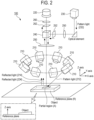
- FIG. 2 is a diagram illustrating an operation process of the apparatus 100 according to an embodiment of the present disclosure.
- the apparatus 100 according to the illustrated embodiment can perform an inspection method using a pattern light and/or an inspection method using coaxial deflectometry.
- the apparatus 100 can determine the three-dimensional shape of the object based on the inspection results.
- the determined three-dimensional shape can be used to determine the adequacy of the performed process.
- the process in which the apparatus 100 performs an inspection using an illumination light will be described later as an additional embodiment.
- one or more pattern light sources 210 can irradiate one or more pattern lights 212 toward an object located on a reference plane R.
- the one or more pattern light sources 210 can belong to the pattern light irradiation part 110.
- the one or more pattern light sources 210 can be disposed above the reference plane R to irradiate the one or more pattern lights 212 toward the object along different optical axes.
- the one or more pattern light sources 210 can be disposed at intervals from each other on an imaginary circumference positioned above the reference plane R.
- the one or more pattern lights 212 can be reflected from the object.
- the phase of the pattern light 212 can be changed before and after reflection. That is, the reflected light 214 generated by the reflection of the pattern light 212 on the object can have a phase different from that of the corresponding pattern light 212.
- An image sensor 220 can capture one or more reflected lights 214 generated by the reflection of the one or more pattern lights 212.
- the image sensor 220 can belong to the measurement part 130.
- the image sensor 220 can be disposed to face the object vertically above the region on the reference plane R where the object is located.
- the apparatus 100 can obtain information about the phase of each of the one or more reflected lights 214 and the phase of each of the one or more pattern lights 212.
- the apparatus 100 can determine a primary three-dimensional shape of the object based on a phase change of each of the one or more reflected lights 214 and each of the one or more pattern lights 212.
- the one or more pattern light sources 210 and the separately installed pattern light source 230 can sequentially irradiate one or more pattern lights 232.
- the pattern light source 230 can belong to the DFM part 120.
- the one or more pattern lights 232 can have the same one phase range (e.g., 0 to 7 ⁇ /4).
- each of the one or more pattern lights 232 can be generated by phase shifting one pattern light within the above-described phase range by an integer multiple of a preset phase interval (e.g., ⁇ /2).
- the one or more pattern lights 232 can travel toward a beam splitter 240 through a lens 250 and/or other optical elements (e.g., a mirror). In one embodiment, the pattern light 232 can travel toward the beam splitter 240 via an iris 252.
- the beam splitter 240 can reflect one or more pattern lights 232 toward the object.
- the beam splitter 240 and one or more lenses 250 can change optical paths of the one or more pattern lights 232 so that a light beam of light corresponding to each phase in the above-described phase range spreads, and arrives at each point of the partial region A of the upper surface of the object.
- the optical path of the light corresponding to each phase of the pattern light 232 can be changed (adjusted) so that the light corresponding to one phase (e.g., 3 ⁇ /4) of the above-described phase range (e.g., 0 to 7 ⁇ /4) of the pattern light 232 arrives at each point on the plane corresponding to the aforementioned partial region A.
- the beam splitter 240 and the one or more lenses 250 can be disposed on the optical path of the pattern light 232 so that they can change the optical path.
- the beam splitter 240 and the one or more lenses 250 can belong to the DFM part 120.
- Each of the one or more pattern lights 232 whose optical paths are changed (adjusted) can reach the object. Since the lights corresponding to the respective phases are irradiated over the entire partial region A of the upper surface of the object in a dispersed manner, the light corresponding to the average amount of the pattern lights 232 can arrive at each point of the partial region A. Each of the one or more pattern lights 232 arriving at the partial region A can be reflected from the partial region A.
- the light (hereinafter referred to as reflected light 234) generated by the reflection of the pattern light 232 can sequentially pass through the lens 250 and the beam splitter 240.
- the reflected light 234 can pass through an iris 262 and, if necessary, can pass through an additionally disposed lens 260 to reach the image sensor 220.
- the image sensor 220 can capture each of the one or more reflected lights 234.
- the iris 252 passes the pattern light 232 toward the beam splitter 240, and the iris 262 passes the reflected light 234 traveling from the partial region A to the image sensor 220. Accordingly, the light amount value of the reflected light 234 captured by the image sensor 220 can be determined according to the light amount of the light passing through the iris 252, reflected by the partial region A and passing through the iris 262.
- the light captured by the image sensor 220 can be the light corresponding to the partial phase range (e.g., 3 ⁇ /4 to 5 ⁇ /4) of the above-described phase range (e.g., 0 to 7 ⁇ /4) of the initially irradiated pattern light 232. That is, the amount of the light passing through the iris 262 and captured by the image sensor 220 can vary according to the degree at which the upper surface of the object or the partial region A is tilted with respect to the reference plane R. By using this principle, it is possible to derive the degree of tilt of the reflective surface based on the amount of captured reflected light, which can be referred to as deflectometry in the present disclosure.
- the deflectometry when the pattern light 232 incident on the object and the reflected light 234 reflected from the object travel along substantially the same optical axis, the deflectometry can be referred to as coaxial deflectometry. The specific principle of the deflectometry will be described later.
- the apparatus 100 can determine the angle of the upper surface of the object with respect to the reference plane R based on the each light amount value of the one or more reflected lights 234.
- the apparatus 100 can determine a secondary three-dimensional shape by correcting the previously determined primary three-dimensional shape by using the determined angle of the upper surface. That is, the apparatus 100 can correct the upper surface indicated by the primary three-dimensional shape by using the information on the angle of the upper surface measured according to the deflectometry and can derive a new corrected three-dimensional shape, i.e., a secondary three-dimensional shape.
- the correction can be performed by a method of overriding the angle of the upper surface indicated by the primary three-dimensional shape with the angle of the upper surface derived according to the deflectometry. In one embodiment, the correction can be performed by determining an average value of the angle of the upper surface indicated by the primary three-dimensional shape and the angle of the upper surface derived according to the deflectometry as an angle of the upper surface indicated by the secondary three-dimensional shape.
- the secondary three-dimensional shape is the final three-dimensional shape of the object, and can be used to determine the adequacy of a process such as a mounting process or the like.
- FIG. 3 is a block diagram of the apparatus 100 according to an embodiment of the present disclosure.
- the apparatus 100 can include one or more pattern light sources 210, an image sensor 220, a pattern light source 230, a beam splitter 240, one or more lenses 250, one or more processors 310 and/or one or more memories 320.
- at least one of these components of the apparatus 100 can be omitted, or other components can be added to the apparatus 100.
- some components can be integrally implemented, or can be implemented as a singular entity or plural entities.
- one or more processors can be referred to as a processor.
- processor can mean one processor or a set of two or more processors, unless the context clearly indicates otherwise.
- one or more memories can be referred to as a memory.
- memory can mean one memory or a set of two or more memories, unless the context clearly indicates otherwise.
- at least some of the internal and external components of the apparatus 100 can be connected to each other through a bus, a general-purpose input/output (GPIO) device, a serial peripheral interface (SPI), a mobile industry processor interface (MIPI), or the like to transmit and receive data and/or signals.
- GPIO general-purpose input/output
- SPI serial peripheral interface
- MIPI mobile industry processor interface
- Each of the one or more pattern light sources 210 can irradiate one or more pattern lights 212 as described above.
- the pattern light sources 210 can generate the pattern lights 212 in various ways.
- the patterns of the pattern lights 212 can be formed by a digital method or an analog method.
- the digital method include a liquid crystal transmission method using an LCD (Liquid Crystal Display), a liquid crystal reflection method using an LCoS (Liquid Crystal on Silicon), and a mirror reflection method using a DMD (Digital Micromirror Device) or DLP (Digital Light Processing).
- Examples of the analog method include a method of forming a pattern by using a pattern such as a periodic pattern, a gradient pattern, a lattice pattern or the like.
- the one or more pattern light sources 210 can be disposed above the reference plane R to irradiate pattern lights 212 along different optical axes.
- four pattern light sources 210 can be arranged at intervals of about 90 degrees on an imaginary circumference (4-way).
- eight pattern light sources 210 can be arranged at intervals of about 45 degrees on an imaginary circumference (8-way).
- the pattern light sources 210 can sequentially irradiate one or more pattern lights 212 phase-shifted to four buckets.
- the one or more pattern lights 212 can be generated by phase-shifting one pattern light by an integer multiple of a preset phase interval (e.g., ⁇ /2).
- the image sensor 220 can capture one or more reflected lights 214 and the reflected light 234 as described above.
- the image sensor 220 can be implemented as a charge coupled device (CCD) or a complementary metal oxide semiconductor (CMOS) sensor.
- CCD charge coupled device
- CMOS complementary metal oxide semiconductor
- the pattern light source 230 can generate and irradiate pattern lights 232 in various ways. In one embodiment, the pattern light source 230 can sequentially irradiate one or more pattern lights 232 phase-shifted to four buckets. In one embodiment, if the pattern lights 232 obtained by phase-shifting the pattern light formed in one direction (hereinafter referred to as a w-axis direction) to four buckets and the pattern lights 232 obtained by phase-shifting the pattern light formed in a direction (hereinafter referred to as a v-axis direction) perpendicular to the w-axis direction to four buckets are used, a total of 8 (4+4) pattern lights 232 can be sequentially irradiated. Accordingly, a total of eight images can be captured and used to determine the angle of the upper surface of the object.
- the beam splitter 240, the one or more lenses 250 and/or other optical elements described above can be variously implemented by optical elements according to methods known in the art of the present disclosure.
- the beam splitter 240 and/or the one or more lenses 250 can be arranged to change the optical paths of the aforementioned pattern lights 232 for deflectometry.
- the processor 310 can adjust the positions, arrangements and related parameters of the beam splitter 240 and/or the one or more lenses 250 so that the beam splitter 240 and/or the one or more lenses 250 can change the optical paths of the aforementioned pattern lights 232.
- the apparatus 100 can also include the iris 252 and the iris 262 described above.
- the processor 310 can control at least one component of the apparatus 100 connected to the processor 310 by driving software (e.g., instructions, programs, etc.). In addition, the processor 310 can perform various operations such as calculation, treatment, data generation, processing, and the like related to the present disclosure. In addition, the processor 310 can load data or the like from the memory 320 or can store data or the like in the memory 320. In one embodiment, the processor 310 can determine a primary three-dimensional of the object based on the phase changes of the one or more reflected lights 214 from the one or more pattern lights 212. In addition, the processor 310 can determine an angle of the upper surface of the object with respect to the reference plane R based on the light amount values of the one or more reflected lights 234 according to deflectometry. The processor 310 can determine a second (final) three-dimensional shape by correcting the primary three-dimensional shape using the determined angle of the upper surface.
- driving software e.g., instructions, programs, etc.
- the processor 310 can perform various operations such as
- the memory 320 can store various kinds of data.
- the data stored in the memory 320 is acquired, processed, or used by at least one component of the apparatus 100, and can include software (e.g., instructions, programs, etc.).
- the memory 320 can include a volatile memory and/or a non-volatile memory.
- the instructions or programs are software stored in the memory 320, and can include an operating system and an application for controlling the resources of the apparatus 100, and/or middleware for providing various functions to the application so that the application can utilize the resources of the apparatus 100.
- the memory 320 can store instructions that cause the processor 310 to perform calculation when executed by the processor 310.
- the apparatus 100 can further include a communication interface (not shown).
- the communication interface can perform wireless or wired communication between the apparatus 100 and a server, or between the apparatus 100 and another apparatus.
- the communication interface can perform wireless communication according to a method such as eMBB (enhanced Mobile Broadband), URLLC (Ultra Reliable Low-Latency Communications), MMTC (Massive Machine Type Communications), LTE (long-term evolution), LTE-A (LTE Advance), UMTS (Universal Mobile Telecommunications System), GSM (Global System for Mobile communications), CDMA (code division multiple access), WCDMA (wideband CDMA), WiBro (Wireless Broadband), WiFi (wireless fidelity), Bluetooth, NFC (near field communication), GPS sensor 12 (Global Positioning System), GNSS (global navigation satellite system) or the like.
- eMBB enhanced Mobile Broadband
- URLLC Ultra Reliable Low-Latency Communications
- MMTC Massive Machine Type Communications
- LTE long-term evolution
- LTE-A LTE Advance
- the communication interface can perform wired communication according to a method such as USB (Universal Serial Bus), HDMI (High Definition Multimedia Interface), RS-232 (Recommended Standard-232), POTS (Plain Old Telephone Service) or the like.
- the processor 310 can control the communication interface to obtain information necessary to implement the technique according to the present disclosure from a server.
- the information obtained from the server can be stored in the memory 320.
- the information obtained from the server can include information about a substrate or an object, information about the reference plane R, and reference information to be described later.
- FIGS. 4 to 8 are diagrams for explaining the principle of the above-described coaxial deflectometry.
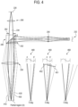
- FIG. 4 is a diagram illustrating a process in which the pattern lights 232 are irradiated to the object according to an embodiment of the present disclosure.
- the light path of each of the one or more pattern lights 232 can be changed so that a beam of light corresponding to each phase in the corresponding phase range (e.g., 0 to 7 ⁇ /4) spreads, and arrives at each point of a partial region A of the upper surface of the object.
- a beam of light corresponding to each phase in the corresponding phase range e.g., 0 to 7 ⁇ /4
- the pattern light source 230 can irradiate pattern lights 232 corresponding to one phase range.
- the optical paths 410, 420 and 430 of the lights corresponding to arbitrary three phases within the aforementioned phase range are shown.
- Each light can be irradiated to the partial region A of the upper surface of the object through the one or more lenses 250, the iris 252 and/or the beam splitter 240.
- each beam of light corresponding to one phase among the phase range can be irradiated over the entire partial region A in a dispersed manner. That is, the light 410 corresponding to one phase can be irradiated to arrive at each point of the surface corresponding to the partial region A.
- the lights 420 and 430 corresponding to other phases of the pattern light 232 can also be irradiated to the object in the same manner. Therefore, all the lights corresponding to the respective phases in the above-described phase range can be irradiated to one point of the partial region A on the object. For example, in the illustrated embodiment, all the lights 410, 420, and 430 reach each point of the partial region A on the object. Accordingly, the lights having an average light amount of the pattern lights 232 corresponding to the above-described phase range can be irradiated to the entire partial region A of the object.
- the reflected light 234 generated by reflecting the pattern light 232 from the partial region A can pass through the iris 262 and can be inputted to the image sensor 220.
- the iris 262 can correspond to a part of the phase range of the pattern light 232 irradiated from the pattern light source 230.
- an average amount of the lights corresponding to the partial phase range can be captured by the image sensor 220.
- the object can be tilted at an angle of 3 degrees with respect to the reference plane R.
- the phase range of the pattern light 232 passed through the iris 252 can be the section indicated by the straight line 451
- the phase range of the reflected light 234 passed through the iris 262 can be the section indicated by the straight line 452.
- the light having an optical path passing through both the iris 252 and the iris 262 can be the light corresponding to the phase section indicated by A and A'.
- the light amount of the reflected light 234 obtained by the image sensor 220 can be an average light amount of the lights corresponding to the phase section indicated by A and A'.
- the object can be tilted at an angle of 5 degrees with respect to the reference plane R.
- most of the light reflected from one point in the partial region A can not pass through the iris 262. Accordingly, the image sensor 220 can not be able to capture the reflected light 234.
- the angles of the upper surface of the object in the above-described examples 440, 450 and 460 can be exemplary values selected for description.
- the apparatus 100 can determine (derive) the angle of the upper surface of the object.
- FIG. 5 is a diagram illustrating a process in which the reflected lights 234 pass through the iris 262 according to an embodiment of the present disclosure.
- the illustrated example can represent a case in which the upper surface of the object is tilted at a predetermined angle with respect to the reference plane R, as in the above-described example 450.
- the pattern lights 232 having one phase range can be irradiated from the pattern light sources 230 and can be irradiated to the partial region A of the upper surface of the object in a dispersed manner. Since the upper surface of the object is tilted, only a portion of the reflected lights 234 can pass through the iris 262 and can be inputted to the image sensor 220. Among the reflected lights of the lights 410, 420 and 430 incident on the partial region A, only the reflected light whose optical path extends within the range indicated by the thick solid line can pass through the iris 262 and can be inputted to the image sensor 220.
- a portion of the reflected lights inputted to the image sensor 220 can be the light corresponding to a part of the above-described phase range of the pattern lights 232 and reflected from the partial region A on the object.
- the amount of reflected lights 234 obtained by the image sensor 220 can be an average amount of the lights corresponding to the part of the above-described phase range of the pattern lights 232.
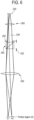
- FIG. 6 is a diagram illustrating a process in which the reflected lights 234 pass through the iris 262 according to an embodiment of the present disclosure.
- a portion A1 of the partial region A of the upper surface of the object can not be tilted with respect to the reference plane R, and the other portion A2 can be tilted with respect to the reference plane R.
- the light reflected from the non-tilted portion A1 can pass through the iris 262 and can be inputted to the corresponding portion of the image sensor 220 (thick solid line), as in the above-described example 440.
- the corresponding portion of the image sensor 220 can receive the average light amount of the lights irradiated from the pattern light source 230 and corresponding to the above-described phase range. Only a part of the light reflected from the tilted portion A2 can pass through the iris 262 and can be inputted to the image sensor 220 (thick dotted line), as in the above-described example 450.
- the corresponding portion of the image sensor 220 can receive the average light amount of only the lights irradiated from the pattern light source 230 and corresponding to a part of the above-described phase range.
- a tilt value at each portion of the partial region A on the object can be obtained by using the average light amount values inputted for the respective portions (pixels) of the image sensor 220.
- FIG. 7 is a view showing the states in the iris 252 of the pattern lights 232 irradiated from the pattern light source 230 according to an embodiment of the present disclosure.
- a pattern of one pattern light 232 can have a period.
- the phase corresponding to one period is assumed to be 2 ⁇
- the pattern of the pattern light can gradually become bright during the period from 0 to ⁇ /2
- the pattern of the pattern light can gradually become dark during the period from ⁇ /2 to 3 ⁇ /2
- the pattern of the pattern light can gradually become bright again during the period from 3 ⁇ /2 to 2 ⁇ .
- the pattern light source 230 can irradiate pattern lights 232 having one phase range. This phase range can be appropriately set as needed.
- the phase range can be set so as not to be one period of a pattern or a multiple of one period of the pattern. That is, the phase range can be set to a range other than the phase range corresponding to 0, 2 ⁇ , 4 ⁇ , ..., and 2n ⁇ . This is because the lights corresponding to the average light amount of the pattern lights 232 are irradiated to the partial region A and, therefore, the lights corresponding to the respective phases of the pattern lights can cancel each other when the pattern lights in the phase range corresponding to one period or a multiple of one period are used. Furthermore, in one embodiment, the phase range can be set to be larger than a phase range corresponding to a half period of the pattern lights and smaller than a phase range corresponding to one period of the pattern lights.
- the phase range can be set to be larger than the phase range corresponding to an (N+1/2) period of the pattern lights (where N is a natural number) and smaller than the phase range corresponding to an (N+1) period of the pattern lights.
- Such a phase range can be set when it is necessary to increase the total amount of pattern lights in order to facilitate the measurement of the reflected light.
- Each of the one or more pattern lights 232 can be generated by phase-shifting one pattern light corresponding to the above-described phase range by an integer multiple of a preset phase interval (e.g., ⁇ /2). In one embodiment, the above-described phase interval can be set to a value greater than 0 and less than ⁇ .
- the one or more pattern lights 232 can be referred to as a 0-th bucket, a first bucket, a second bucket and a third bucket, i.e., four buckets.
- the respective pattern lights 232 generated by the phase shift can also have the above-described phase range ⁇ .
- the respective pattern lights 232 can have a phase range of 0 to ⁇ , a phase range of ⁇ /2 to ⁇ /2+ ⁇ , a phase range of ⁇ to ⁇ + ⁇ , and a phase range of 3 ⁇ /2 to 3 ⁇ /2+ ⁇ .
- the pattern lights 232 for the respective buckets can appear like the illustrated patterns 710 in the iris 252.
- the region of the pattern light passing through the iris 252 can be a circular region 20. Accordingly, the light corresponding to the circular region in the rectangular pattern light irradiated from the pattern light source 230 can be irradiated to the object.
- the apparatus 100 can determine the angle of the upper surface of the object by using only one pattern light 232. However, if the angle of the upper surface of the object is measured by using a plurality of pattern lights, it is possible to reduce various measurement errors such as an error caused by the material of the upper surface of the object, and the like.
- the total light amount value of the pattern light 232 in the pattern light source 230 can be calculated as represented by the following equation.
- I LCOS ⁇ ⁇ ⁇ I 0 + I ° ⁇ sin ⁇ d ⁇
- the processor 310 can derive a phase value of each of the one or more reflected lights 234 from the light amount value of each of the one or more reflected lights 234.
- Equation 2 A and B can correspond to I o and I o , respectively.
- ⁇ (x, y) can be a phase value of the reflected light reflected from one point (x, y) of the partial region A.
- ⁇ (t) can represent the above-described phase shift amount of the pattern light 232.
- the light amount values I 1 , I 2 , I 3 and I 4 of the reflected lights generated by the plurality of pattern lights 232 (i.e., four buckets) phase-shifted at a phase interval of ⁇ /2 and reflected from the partial region A can be represented by the following equation 3.
- Equation 3 can be arranged by substituting each phase shift amount ⁇ (t) in Equation 2.
- the image sensor 220 can capture the light having an average amount of lights corresponding to a part of the phase range of the pattern lights 232.
- the light corresponding to the part of the phase range can vary depending on the angle of the upper surface of the object and/or the bucket of the irradiated pattern light 232. That is, even for the object tilted at the same angle, the configuration of the light corresponding to the above-described part of the phase range can vary according to how much the irradiated pattern light 232 is phase-shifted.
- the amounts of the reflected lights for the respective buckets can be the aforementioned I 1 , I 2 , I 3 and I 4 .
- the light amount values I 1 , I 2 , I 3 and I 4 of the respective reflected lights are values that can be measured by the image sensor 220.
- A, B and ⁇ can be derived by using the above four equations for I 1 , I 2 , I 3 and I 4 . Since there are three unknowns, at least three equations are required, and therefore, the measurement through the use of three or more different pattern lights 232 can have to be performed at least three times. Accordingly, by rearranging Equation 3, the phase value ⁇ of the reflected light can be derived by the following equation.
- ⁇ tan ⁇ 1 I 4 ⁇ I 2 I 1 ⁇ I 3
- phase values of the one or more reflected lights 234 can be derived from the light amount values of the one or more reflected lights 234, respectively.
- This derivation process can be performed by the processor 310.
- the memory 320 of the apparatus 100 can further store the reference information.
- the reference information can indicate a relationship between the angles of the upper surface of the object with respect to the reference plane R and the phase values of the reflected lights 234.
- the numerical values indicated by the illustrated reference information are exemplary values, and the values of the reference information can be changed according to embodiments.
- the relationship between the phase values indicated by the reference information and the tilt angles of the object can be stored in the memory 220 as a database through measurement and calculation.
- the processor 310 can determine the angle of the upper surface of the object with respect to the reference plane R based on the phase value of the reflected light 234 and the reference information.
- the processor 310 can determine a corrected second (final) three-dimensional shape by correcting the upper surface indicated by the primary three-dimensional shape through the use of the determined angle of the upper surface.
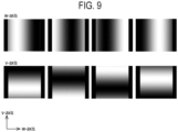
- each of the one or more pattern lights 212 and 232 can have a pattern in the w-axis direction or in the v-axis direction perpendicular to the w-axis.
- the orientations of the patterns of the pattern lights 212 and 232 can be set differently for the respective buckets.
- an error in determining the three-dimensional shape of the object can be reduced by using a plurality of patterns formed in the respective directions.
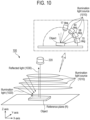
- FIG. 10 is a diagram illustrating an inspection process using illumination lights of the apparatus 100 according to an embodiment of the present disclosure. Some of the components of the apparatus 100 described above are arbitrarily omitted.
- the apparatus 100 can further perform an inspection using illumination lights.
- the apparatus 100 can determine the primary three-dimensional shape of the object by additionally reflecting the inspection result obtained through the use of the illumination lights in addition to the inspection result obtained through the use of the pattern lights described above.
- the apparatus 100 can further include one or more illumination light sources 1010.
- the illumination light sources 1010 can belong to the illumination light irradiation part 140. Each of the illumination light sources 1010 can irradiate the illumination light 1020 toward the object located on the reference plane R.
- one illumination light source 1010 can be implemented in such a form as to include a plurality of illumination light sources (e.g., LED lights) arranged to be spaced apart from each other at predetermined intervals on a circumference. The corresponding circumference can be disposed parallel to the reference plane R.
- one illumination light source 1010 can be implemented as one illumination light source having a columnar shape. The respective illumination light sources 1010 can be disposed above the reference plane R or the object.
- the respective illumination light sources 1010 can be arranged to irradiate the illumination lights to the object along optical axes tilted at one or more angles (e.g., 17 degrees, 40 degrees, 58 degrees, 70 degrees, etc.) with respect to the reference plane R. In one embodiment, a total of four illumination light sources 1010 can be used as shown.
- the illumination lights can be lights according to one or more wavelengths. In one embodiment, the illumination lights can be a red light, a green light or a blue light.
- the illumination light sources 1010 can be implemented as RGB light sources, and can include a red light source, a green light source and/or a blue light source. In one embodiment, the illumination light sources 1010 can simultaneously irradiate at least two lights, and can simultaneously irradiate red, green and blue lights to generate a white light.
- the illumination lights 1020 can be reflected from the object.
- the image sensor 220 can capture the lights (hereinafter referred to as reflected lights 1030) formed by the reflection of the illumination lights 1020.
- the amount of lights captured by the image sensor 220 can vary depending on the angles at which the illumination lights 1020 are irradiated to the object and the angles at which the reflected lights 1030 are reflected from the object.
- the shape of the object can be determined based on the light amount values changed before and after reflection.
- the processor 310 can obtain a change in the light amount of each of the one or more reflected lights 1030 from each of the illumination lights 1020 according to one or more wavelengths.
- the processor 310 can determine the above-described primary three-dimensional shape of the object based on the change in the light amount.
- the processor 310 can determine the primary three-dimensional shape of the object by both the inspection result obtained using the pattern lights and the inspection result obtained using the illumination lights.
- the processor 310 can determine the primary three-dimensional shape of the object based on the phase change of each of the one or more reflected lights 214 from each of the one or more pattern lights 212 and the change in the light amount of each of the one or more reflected lights 1030 from each of the illumination lights 1020 according to one or more wavelengths. Thereafter, as described above, the processor 310 can determine a second (final) three-dimensional shape of the object by correcting the primary three-dimensional shape through the use of the determined angle of the upper surface. In one embodiment, if four illumination light sources 1010 are used to sequentially irradiate a red light, a green light and a blue light, a total of 12 (4 ⁇ 3) illumination lights can be irradiated to the object. Accordingly, a total of 12 reflected lights can be captured by the image sensor 220 and can be used to determine the primary three-dimensional shape of the object.
- FIG. 11 is a diagram illustrating a process in which the pattern light source 230 additionally irradiates a white light 1110 according to an embodiment of the present disclosure. Some of the components of the apparatus 100 described above are arbitrarily omitted. In one embodiment, the pattern light source 230 of the apparatus 100 can further irradiate the white light 1110. A more accurate primary three-dimensional shape of the object can be determined using the information about the reflected light 1120 of the white light 1110.
- the pattern light source 230 can irradiate at least one monochromatic light such as a red light, a green light, a blue light and a white light.
- the pattern light source 230 can irradiate a white light 1120.
- a white illumination light without a pattern can be irradiated from the pattern light source 230.
- the white light 1120 can travel along an optical path similar to that of the above-described pattern light 232.
- the beam splitter 240 and the one or more lenses 250 can change the optical path of the white light 1110 so that the white light 1110 arrives at the upper surface of the object.
- the white light 1110 can travel to the beam splitter 240 via the lens 250, the iris 252 and other optical elements.
- the beam splitter 240 can change the optical path of the white light 1110 so that the white light 1110 faces the upper surface of the object.
- the white light 1110 can be reflected from the upper surface of the object. Depending on the shape of the object, the light amount of the white light 1110 can be changed before and after reflection. That is, the light amount of the white light 1110 and the light amount of the reflected light 1120 can be different from each other.
- the reflected light 1120 can travel toward the beam splitter 240, and the beam splitter 240 can pass the reflected light 1120 to the image sensor 220.
- the image sensor 220 can capture the reflected light 1120.
- the processor 310 can determine the shape of the object based on the value of the light amount changed before and after reflection. That is, the processor 310 can obtain a change in the light amount of the reflected light 1120 from the white light 1110 and can determine the primary three-dimensional shape of the object based on the change in the light amount. In one embodiment, the processor 310 can determine the primary three-dimensional shape of the object by using both the inspection result obtained using the pattern light and the inspection result obtained using the white light. In this case, the processor 310 can determine the primary three-dimensional shape of the object based on the phase change of each of the one or more reflected lights 214 from each of the one or more pattern lights 212 and the change in the light amount of the reflected light 1120 from the white light 1110. Thereafter, as described above, the processor 310 can determine a second (final) three-dimensional shape of the object by correcting the primary three-dimensional shape using the determined angle of the upper surface.
- the apparatus 100 can determine the secondary three-dimensional shape by performing the inspection using the coaxial deflectometry only when a preset criterion is satisfied. Otherwise, the apparatus 100 can determine only the primary three-dimensional shape. This is to reduce the time required for the inspection process by performing an additional inspection on the upper surface of the object only when necessary.
- the apparatus 100 when the reflectance of the upper surface of the object is equal to or greater than a preset reference reflectance, the apparatus 100 can additionally perform an inspection on the object using the coaxial deflectometry. If the upper surface of the object is a mirror surface or a surface which is mirror-finished after a reflow process, it can be difficult to accurately measure the shape of the upper surface of the object only by the inspection using the illumination lights or the pattern lights. Accordingly, when it is determined that the upper surface of the object is a mirror surface (i.e., when the reflectance is equal to or greater than a preset reference reflectance), the apparatus 100 can additionally perform an inspection using the coaxial deflectometry.
- the processor 310 can obtain light amount information of the white light 1110 from the pattern light source 230 and can obtain light amount information of the reflected light 1120 from the image sensor 220.
- the processor 310 can derive the reflectance of the upper surface of the object based on the change in the light amount of the reflected light 1120 from the white light 1110.
- the processor 310 can control the pattern light source 230 to sequentially irradiate the one or more pattern lights 232 described above.
- the information about the preset reference reflectance can be stored in the memory 320.
- the apparatus 100 can first perform an inspection using pattern lights and then perform an inspection using deflectometry. That is, the reflected light 214 can be captured by first irradiating the pattern light 212, and then the reflected light 234 can be captured by irradiating the pattern light 232. In one embodiment, the inspection using the illumination lights can be performed prior to the inspection using the deflectometry.
- the apparatus 100 can determine a three-dimensional shape by imaging the reference plane R, the object, or both the reference plane R and the object using pattern lights, and then can derive the angle of the upper surface of the object using deflectometry.
- the information on the upper surface of the object relative to the reference plane R and the information on the three-dimensional shape of the object can be accurately derived based on the information on the angle of the upper surface of the object derived using the deflectometry.
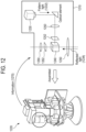
- FIG. 12 is a diagram illustrating an apparatus 1210 according to an embodiment of the present disclosure.
- the apparatus 1210 is an apparatus corresponding to the above-described DFM part 120 and can determine the angle of the upper surface of the object located on the reference plane R.
- At least one component in the apparatus 1210 can be implemented as a removable device and can be coupled to an apparatus 1220. If the apparatus 1210 is not coupled, a coaxial 2D light source can be attached to the location where the apparatus 1210 was coupled.
- the coaxial 2D light source can irradiate at least one monochromatic light selected from a red light, a green light, a blue light and a white light.
- the coaxial 2D light source can be implemented through an optical element such as an LED or the like.
- the apparatus 1220 can be an apparatus including the pattern light irradiation part 110, the measurement part 130 and/or the illumination light irradiation part 140 described above.
- the apparatus 1220 can determine the above-described primary three-dimensional shape of the object on the reference plane R.
- the apparatus 1210 is coupled to the apparatus 1220, there can be provided a configuration similar to that of the apparatus 100 described above.
- the combination of the apparatus 1210 and the apparatus 1220 can determine the above-described second (final) three-dimensional shape of the object in the same manner as performed by the apparatus 100. That is, the apparatus 1220 can determine a primary three-dimensional shape of the object by performing an inspection using pattern lights and/or an inspection using illumination lights, and the apparatus 1210 can determine an angle of the upper surface of the object.
- a secondary three-dimensional shape can be determined by correcting the primary three-dimensional shape of the object using the angle of the upper surface.
- the process of correcting the primary three-dimensional shape of the object and determining the secondary three-dimensional shape can be performed by the apparatus 1210 or the apparatus 1220.
- the beam splitter 1240 and the one or more lenses 1250 can change the optical paths of the one or more pattern lights 1232.
- the beam splitter 1240 and the one or more lenses 1250 can correspond to the beam splitter 240 and the one or more lenses 250, respectively.
- the beam splitter 1240 and the one or more lenses 1250 can change the optical paths of the one or more pattern lights 1232 so that the lights corresponding to the respective phases in the above-described phase range can reach the partial region A of the upper surface of the object in a dispersed manner.
- other necessary optical elements e.g., mirrors
- the pattern lights 1232 can pass through the iris 1252 before being inputted to the beam splitter 1240.
- the one or more pattern lights 1232 can be reflected from the partial region A of the object.
- the lights (hereinafter referred to as reflected lights 1234) formed by the reflection of the pattern lights 1232 can pass through the beam splitter 1240, the iris 1262, other lenses 1260 and the like, and can be inputted to the image sensor of the apparatus 1220.
- This image sensor can correspond to the above-described image sensor 220.
- the apparatus 1210 can obtain information 1270 about the one or more reflected lights 1234 from the apparatus 1220.
- the apparatus 1210 can determine an angle of the upper surface of the object with respect to the reference plane R based on the information 1270.
- the process of determining the angle of the upper surface can be the same as the process described above in respect of the apparatus 100.
- the information 1270 can include information indicating a light amount value of each of the one or more reflected lights 1234.
- the apparatus 1220 is an apparatus including the pattern light irradiation part 110, the measurement part 130 and/or the illumination light irradiation part 140 described above, and can perform an inspection using the pattern lights and/or the illumination lights.
- the apparatus 1220 can include one or more pattern light sources (corresponding to the pattern light sources 210), an image sensor (corresponding to the image sensor 220), and/or a processor (corresponding to the processor 310).
- the pattern light sources can irradiate one or more pattern lights (corresponding to the pattern lights 212) to the object.
- the image sensor can capture the reflected lights (corresponding to the reflected lights 214) of the pattern lights (corresponding to the pattern lights 212).
- the image sensor can also capture the reflected lights (corresponding to the reflected lights 234) of the pattern lights 1232.
- the processor can determine a primary three-dimensional shape of the object based on the captured reflected lights, and can transmit information indicating the determined primary three-dimensional shape to the apparatus 1210.
- FIG. 13 is a block diagram of an apparatus 1210 according to an embodiment of the present disclosure.
- the apparatus 1210 can include a pattern light source 1230, a beam splitter 1240, one or more lenses 1250, a communication interface 1330, one or more processors 1310 and/or one or more memories 1320.
- at least one of these components of the apparatus 1210 can be omitted, or other components can be added to the apparatus 1210.
- some components can be integrally implemented, or can be implemented as a singular entity or plural entities.
- At least some of the internal and external components of the apparatus 1210 can be connected to each other through a bus, a general-purpose input/output (GPIO) device, a serial peripheral interface (SPI), a mobile industry processor interface (MIPI), or the like to transmit and receive data and/or signals.
- GPIO general-purpose input/output
- SPI serial peripheral interface
- MIPI mobile industry processor interface
- the communication interface 1330 can be implemented in a manner similar to the communication interface of the apparatus 100 described above.
- the communication interface 1330 can be controlled by the processor 1310 to communicate with the apparatus 1220.
- the communication interface 1330 can obtain information 1270 about one or more reflected lights 1234 from the apparatus 1220.
- the processor 1310 can be implemented in a manner similar to the processor 310 of the apparatus 100 described above.
- the processor 1310 can control the communication interface 1330 to obtain information 1270 on one or more reflected lights 1234 and can determine the angle of the upper surface of the object with respect to the reference plane R based on the information 1270.
- the processor 1310 of the apparatus 1210 can derive a phase value of each of the one or more reflected lights 1234 from a light amount value of each of the one or more reflected lights 1234.
- the processor 1310 can determine an angle of the upper surface of the object with respect to the reference plane R based on the derived phase value. This process can correspond to the process in which the above-described processor 310 derives the phase value from the light amount value of each of the reflected lights 234 and determines the angle of the upper surface from the phase value.
- the memory 1320 can store reference information similarly to the memory 320, and the processor 1310 can determine the angle of the upper surface based on the phase value of each of the reflected lights 1234 and the reference information.
- the apparatus 1210 can transmit information indicating the derived angle of the upper surface to the apparatus 1220 so that the apparatus 1220 can determine a secondary three-dimensional shape.
- the processor 1310 can control the communication interface 1330 to transmit information indicating the derived angle of the upper surface to the apparatus 1220.
- the apparatus 1220 can determine the primary three-dimensional shape of the object through an inspection using pattern lights and/or illumination lights. The information indicating the angle of the upper surface can be used by the apparatus 1220 to determine a secondary three-dimensional shape by correcting the upper surface of the object indicated by the primary three-dimensional shape.
- the pattern light source 1230 can further irradiate a white light
- the beam splitter 1240 and the one or more lenses 1250 can change the optical path of the white light so that the white light arrives at the upper surface of the object. This can correspond to irradiating the white light 1110 by the pattern light source 230 of the apparatus 100 described above.
- the white light can be reflected from the upper surface of the object.
- the apparatus 1220 can capture the reflected light and can determine the primary three-dimensional shape of the object based on a change in the light amount of the reflected light from the white light.
- the second light source (e.g., the pattern light source 230) can sequentially irradiate one or more second pattern lights (e.g., the pattern lights 232) having one phase range.
- the beam splitter 240 and the one or more lenses 250 can change optical paths of the one or more second pattern lights (e.g., the pattern lights 232) so that a beam of light corresponding to a respective phase of the phase range spreads, and arrives at each point of a partial region A of the upper surface of the object.
- the image sensor 220 can capture one or more second reflected lights (e.g., the reflected lights 234) generated by reflecting the one or more second pattern lights (e.g., the pattern lights 232) from the partial region A.
- step S1760 of determining the first three-dimensional shape can include determining, by the processor 310, a second three-dimensional shape (e.g., the primary three-dimensional shape) of the object based on each of the phase changes of the one or more first reflected lights (e.g., the reflected lights 214) from the one or more first pattern lights (e.g., the pattern lights 212).
- step S 1760 can include deriving, by the processor 310, a phase value of each of the one or more second reflected lights (e.g., the reflected lights 234) from the each light amount value of the one or more second reflected lights (e.g., the reflected lights 234).
- the apparatus 100 can further include one or more third light sources (e.g., illumination light sources 1010).
- determining the second three-dimensional shape (e.g., the primary three-dimensional shape) of the object can include determining, by the processor 310, a second three-dimensional shape (e.g., a primary three-dimensional shape) of the object based on each of changes in the phases of the one or more first reflected lights (e.g., the reflected lights 214) from the one or more first pattern lights (e.g., the pattern lights 212) and each of changes in the light amounts of the one or more third reflected lights (e.g., the reflected lights 1030) from the illumination lights 1020 according to one or more wavelengths.
- a second three-dimensional shape e.g., a primary three-dimensional shape
- the method 1700 can further include: irradiating a white light 1110 by a second light source (e.g., the pattern light source 230); changing an optical path of the white light 1110 by the beam splitter 240 and the one or more lenses 250 so that the white light 1110 arrives at the upper surface of the object; and/or capturing, by the image sensor 220, a fourth reflected light (e.g., the reflected light 1120) generated by reflecting the white light 1110 from the upper surface of the object.
- a second light source e.g., the pattern light source 230
- changing an optical path of the white light 1110 by the beam splitter 240 and the one or more lenses 250 so that the white light 1110 arrives at the upper surface of the object
- a fourth reflected light e.g., the reflected light 1120
- determining the second three-dimensional shape can include determining, by the processor 310, the second three-dimensional shape (e.g., the primary three-dimensional shape) of the object based on each of changes in the phases of the one or more first reflected lights (e.g., the reflected lights 214) from the one or more first pattern lights (e.g., the pattern lights 212) and a change in the light amount of the fourth reflected light (e.g., the reflected light 1120) from the white light 1110.
- the method 1700 can further include: deriving, by the processor 310, a reflectance of the upper surface of the object based on a change in the light amount of the fourth reflected light (e.g., the reflected light 1120) from the white light 1110; and/or controlling a second light source (e.g., the pattern light source 230) to sequentially irradiate one or more second pattern lights (e.g., the pattern lights 232) when the reflectance of the upper surface of the object is equal to or greater than a preset reference reflectance.
- a second light source e.g., the pattern light source 230
- FIG. 15 is a diagram illustrating an example of a method 1800 for determining an angle of an upper surface of an object, which can be performed by the apparatus 1210 according to the present disclosure.
- the method 1800 can include: step S1810 of sequentially irradiating one or more first pattern lights; step S1820 of changing optical paths of the first pattern lights so that a beam of light corresponding to a respective phase of a phase range spreads, and arrives at each point of a partial region; step S1830 of obtaining first information about one or more first reflected lights from a first apparatus; and/or step S1840 of determining an angle of an upper surface of an object with respect to a reference plane based on the first information.
- the first light source e.g., the pattern light source 1230
- the first light source 1230 can sequentially irradiate one or more first pattern lights (e.g., the pattern lights 1232) having one phase range.
- a beam splitter e.g., the beam splitter 1240
- one or more lenses e.g., the lens 1250
- the first pattern lights e.g., the pattern lights 1232
- a first processor e.g., the processor 1310 can obtain, from a first apparatus (e.g., the apparatus 1220), first information (e.g., the information 1270) about one or more first reflected lights (e.g., the reflected lights 1234) generated by reflecting the one or more first pattern lights (e.g., the pattern lights 1232) from the partial region A.
- first information e.g., the information 1270
- first reflected lights e.g., the reflected lights 1234
- first pattern lights e.g., the pattern lights 1232
- the first processor e.g., the processor 1310 can determine an angle of the upper surface with respect to the reference plane R based on the first information (e.g., the information 1270).
- determining the angle of the upper surface can include deriving, by the first processor (e.g., the processor 1310), a phase value of each of the one or more first reflected lights (e.g., the reflected lights 1234) from the each light amount value of the one or more first reflected lights (e.g., the reflected lights 1234); and/or determining, by the first processor (e.g., the processor 1310), the angle of the upper surface with respect to the reference plane R based on the derived phase value.
- the first processor e.g., the processor 1310
- the method 1800 can further include: obtaining, by the first processor (e.g., the processor 1310), third information indicating a first three-dimensional shape (e.g., the primary three-dimensional shape) of the object from the first apparatus (e.g., the apparatus 1220); and/or determining, by the first processor (e.g., the processor 1310), a second three-dimensional shape (e.g., the secondary three-dimensional shape) of the object by correcting the upper surface of the object indicated by the first three-dimensional shape (e.g., the primary three-dimensional shape) based on the angle of the upper surface.
- the first processor e.g., the processor 1310
- a second three-dimensional shape e.g., the secondary three-dimensional shape
- the method 1800 can further include: irradiating, by a first light source (e.g., the pattern light source 1230), a white light; and/or changing, by a beam splitter (e.g., the beam splitter 1240) and one or more lenses (e.g., the lens 1250), an optical path of the white light so that the white light arrives at the upper surface of the object.
- a first light source e.g., the pattern light source 1230
- a white light e.g., a white light
- a beam splitter e.g., the beam splitter 1240
- one or more lenses e.g., the lens 1250
- the method 1800 can further include: obtaining, by the first processor (e.g., the processor 1310), fourth information indicating a reflectance of the upper surface from the first apparatus (e.g., the apparatus 1220) by controlling a communication interface 1330; and/or controlling a first light source (e.g., the pattern light source 1230) to sequentially irradiate one or more first pattern lights (e.g., the pattern lights 1232) when the reflectance of the upper surface is equal to or greater than a preset reference reflectance.
- a first light source e.g., the pattern light source 1230
- the determination of the three-dimensional shape of the object can be improved by efficiently measuring the tilt of the upper surface of the object using the light amount of the reflected light reflected from the object (e.g., a device). Whether the entire substrate mounting process is properly performed can be inspected through the three-dimensional shape of the object.
- the tilt of the object is not inspected based on the image formation position of the reflected light from the object. Therefore, it is possible to facilitate the downsizing of the inspection apparatus.
- the tilt of the object is not inspected based on the diffraction pattern formed in the air above the object. Therefore, it is possible to perform a noise-robust inspection.
- the software can be software for implementing the various embodiments of the present disclosure described above.
- the software can be inferred from various embodiments of the present disclosure by programmers in the art to which the present disclosure belongs.
- the software can be instructions (e.g., code or code segments) or programs that can be read by a device.
- the device is a device capable of operating according to instructions called from a recording medium, and can be, for example, a computer.
- the device can be the apparatuses 100 and 1210 according to embodiments of the present disclosure.
- the processor of the device can execute the called instructions so that components of the device can perform a function corresponding to the instructions.
- the processor can be one or more processors according to the embodiments of the present disclosure.
- the recording medium can refer to any type of device-readable recording medium in which data is stored.
- the recording medium can include, for example, a ROM, a RAM, a CD-ROM, a magnetic tape, a floppy disk, an optical data storage device, and the like.
- the recording medium can be one or more memories.
- the recording medium can be implemented in a distributed form in computer systems connected by a network.
- the software can be distributed, stored and executed in a computer system or the like.
- the recording medium can be a non-transitory recording medium.
- the non-transitory recording medium refers to a tangible medium irrespective of whether data is stored semi-permanently or temporarily, and does not include a signal propagating in a transitory manner.
Landscapes
- Physics & Mathematics (AREA)
- General Physics & Mathematics (AREA)
- Engineering & Computer Science (AREA)
- Computer Vision & Pattern Recognition (AREA)
- Length Measuring Devices By Optical Means (AREA)
- Manufacturing & Machinery (AREA)
- Theoretical Computer Science (AREA)
- Immunology (AREA)
- Mathematical Optimization (AREA)
- Analytical Chemistry (AREA)
- Biochemistry (AREA)
- General Health & Medical Sciences (AREA)
- Life Sciences & Earth Sciences (AREA)
- Pathology (AREA)
- Algebra (AREA)
- Mathematical Analysis (AREA)
- Chemical & Material Sciences (AREA)
- Mathematical Physics (AREA)
- Pure & Applied Mathematics (AREA)
- Computer Graphics (AREA)
- Geometry (AREA)
- Software Systems (AREA)
- Health & Medical Sciences (AREA)
- Quality & Reliability (AREA)
Claims (13)
- Deuxième appareil détachable (1210) couplé à un premier appareil (1220) qui détermine une première forme tridimensionnelle d'un objet situé sur un plan de référence, et configuré pour déterminer un angle entre une surface supérieure de l'objet et le plan de référence, le deuxième appareil comprenant :une première source de lumière (1230) configurée pour irradier séquentiellement une ou plusieurs premières lumières de motif ayant une plage de phase ;un séparateur de faisceau (1240) et une ou plusieurs lentilles (1250) configurés pour changer les chemins optiques desdites une ou plusieurs premières lumières de motif de telle sorte qu'un faisceau de lumière correspondant à une phase respective de la plage de phases se disperse et parvienne à chaque point d'une région partielle de la surface supérieure de l'objet ;une interface de communication (1330) configurée pour communiquer avec le premier appareil (1220) ; etun premier processeur (1310) qui est connecté électriquement à la première source de lumière (1230) et à l'interface de communication (1330), et qui est configuré :pour obtenir, auprès du premier appareil (1220), une première information sur une ou plusieurs premières lumières réfléchies générées par réflexion desdites une ou plusieurs premières lumières de motif sur la région partielle ; etpour déterminer l'angle entre la surface supérieure et le plan de référence sur la base de la première information,dans lequel la première information comprend de l'information indiquant chaque valeur de quantité de lumière desdites une ou plusieurs premières lumières réfléchies.
- Deuxième appareil selon la revendication 1, dans lequel le premier processeur (1310) est en outre configuré : pour déterminer l'angle entre la surface supérieure et le plan de référence sur la base de chaque valeur de quantité de lumière desdites une ou plusieurs premières lumières réfléchies.
- Deuxième appareil selon la revendication 2, comprenant en outre : une mémoire (1320) configurée pour stocker de l'information de référence indiquant une relation entre l'angle formé par la surface supérieure et le plan de référence et chaque valeur de quantité de lumière desdites une ou plusieurs premières lumières réfléchies,
dans lequel le premier processeur (1310) est en outre configuré pour déterminer l'angle entre la surface supérieure de l'objet et le plan de référence sur la base de chaque valeur de quantité de lumière desdites une ou plusieurs premières lumières réfléchies et de l'information de référence. - Deuxième appareil selon la revendication 1,dans lequel le premier processeur (1310) est en outre configuré pour contrôler l'interface de communication (1330) afin de transmettre une deuxième information indiquant l'angle entre la surface supérieure et le premier appareil (1220), etdans lequel la deuxième information est utilisée pour que le premier appareil (1220) puisse déterminer une deuxième forme tridimensionnelle de l'objet en corrigeant la surface supérieure de l'objet indiquée par la première forme tridimensionnelle.
- Deuxième appareil selon la revendication 1, dans lequel le premier processeur (1310) est en outre configuré :pour contrôler l'interface de communication (1330) afin d'obtenir une troisième information indiquant la première forme tridimensionnelle de l'objet auprès du premier appareil (1220) ; etpour déterminer une deuxième forme tridimensionnelle de l'objet en corrigeant la surface supérieure de l'objet indiquée par la première forme tridimensionnelle sur la base de l'angle de la surface supérieure.
- Deuxième appareil selon la revendication 1,dans lequel la première source de lumière (1230) est en outre configurée pour irradier une lumière monochromatique, etdans lequel le séparateur de faisceau (1240) et lesdites une ou plusieurs lentilles (1250) sont en outre configurés pour changer un chemin optique de la lumière monochromatique de telle sorte que la lumière monochromatique parvienne sur la surface supérieure.
- Deuxième appareil selon la revendication 6, dans lequel le premier processeur (1310) est en outre configuré :pour contrôler l'interface de communication (1330) afin d'obtenir une quatrième information indiquant une réflectance de la surface supérieure à partir du premier appareil (1220) ; etquand la réflectance de la surface supérieure est supérieure ou égale à une réflectance de référence prédéfinie, pour contrôler la première source de lumière (1230) de manière à irradier séquentiellement lesdites une ou plusieurs premières lumières de motif.
- Deuxième appareil selon la revendication 1, dans lequel chacune desdites une ou plusieurs premières lumières de motif est une lumière de motif générée par le déphasage d'une lumière de motif ayant un motif dans une première direction ou dans une deuxième direction perpendiculaire à la première direction d'un multiple entier d'un intervalle de phase prédéfini.
- Deuxième appareil selon la revendication 1, dans lequel le premier appareil (1220) comprend :
une ou plusieurs deuxièmes sources de lumière (210) configurées pour irradier une ou plusieurs deuxièmes lumières de motif sur l'objet :un capteur d'image (220) configuré pour capturer lesdites une ou plusieurs premières lumières réfléchies et lesdites une ou plusieurs deuxièmes lumières réfléchies générées par réflexion desdites une ou plusieurs deuxièmes lumières de motif sur l'objet ; etun deuxième processeur (310) configuré :pour déterminer la première forme tridimensionnelle de l'objet sur la base desdites une ou plusieurs premières lumières réfléchies et desdites une ou plusieurs deuxièmes lumières réfléchies ; etpour transmettre une troisième information indiquant la première forme tridimensionnelle au deuxième appareil (1210). - Procédé de détermination d'un angle entre une surface supérieure d'un objet et un plan de référence, qui est mis en œuvre par un deuxième appareil détachable (1210) couplé à un premier appareil (1220) qui détermine une première forme tridimensionnelle de l'objet situé sur le plan de référence, comprenant :l'irradiation séquentielle, par une première source de lumière (1230), d'une ou plusieurs premières lumières de motif ayant une plage de phase ;le changement, par un séparateur de faisceau (1240) et une ou plusieurs lentilles (1250), des chemins optiques desdites une ou plusieurs premières lumières de motif de telle sorte qu'un faisceau de lumière correspondant à une phase respective de la plage de phases se disperse et parvienne à chaque point d'une région partielle de la surface supérieure de l'objet ;l'obtention, par un premier processeur (1310) auprès du premier appareil (1220), d'une première information sur une ou plusieurs premières lumières réfléchies générées par réflexion desdites une ou plusieurs premières lumières de motif sur la région partielle ; etla détermination, par le premier processeur (1310), de l'angle entre la surface supérieure et le plan de référence sur la base de la première information,dans lequel la première information comprend de l'information indiquant chaque valeur de quantité de lumière desdites une ou plusieurs premières lumières réfléchies.
- Procédé selon la revendication 10, dans lequel la détermination de l'angle de la surface supérieure comprend : la détermination, par le premier processeur (1310), de l'angle entre la surface supérieure et le plan de référence sur la base de chaque valeur de quantité de lumière desdites une ou plusieurs premières lumières réfléchies.
- Procédé selon la revendication 10, comprenant en outre : la transmission, par le premier processeur (1310), d'une deuxième information indiquant l'angle entre la surface supérieure et le premier appareil (1220),
dans lequel la deuxième information est utilisée pour que le premier appareil (1220) puisse déterminer une deuxième forme tridimensionnelle de l'objet en corrigeant la surface supérieure de l'objet indiquée par la première forme tridimensionnelle. - Procédé selon la revendication 10, comprenant en outre :l'obtention, par le premier processeur (1310), d'une troisième information indiquant la première forme tridimensionnelle de l'objet auprès du premier appareil (1220) ; etla détermination, par le premier processeur (1310), d'une deuxième forme tridimensionnelle de l'objet en corrigeant la surface supérieure de l'objet indiquée par la première forme tridimensionnelle sur la base de l'angle de la surface supérieure.
Priority Applications (1)
| Application Number | Priority Date | Filing Date | Title |
|---|---|---|---|
| EP24206879.9A EP4471371B1 (fr) | 2019-06-28 | 2020-06-29 | Appareil et procédé de détermination de forme tridimensionnelle d'objet |
Applications Claiming Priority (2)
| Application Number | Priority Date | Filing Date | Title |
|---|---|---|---|
| KR20190077638 | 2019-06-28 | ||
| PCT/KR2020/008462 WO2020263055A1 (fr) | 2019-06-28 | 2020-06-29 | Dispositif et procédé de détermination d'une forme tridimensionnelle d'un objet |
Related Child Applications (1)
| Application Number | Title | Priority Date | Filing Date |
|---|---|---|---|
| EP24206879.9A Division EP4471371B1 (fr) | 2019-06-28 | 2020-06-29 | Appareil et procédé de détermination de forme tridimensionnelle d'objet |
Publications (4)
| Publication Number | Publication Date |
|---|---|
| EP3992576A1 EP3992576A1 (fr) | 2022-05-04 |
| EP3992576A4 EP3992576A4 (fr) | 2022-08-31 |
| EP3992576C0 EP3992576C0 (fr) | 2024-10-23 |
| EP3992576B1 true EP3992576B1 (fr) | 2024-10-23 |
Family
ID=74059932
Family Applications (6)
| Application Number | Title | Priority Date | Filing Date |
|---|---|---|---|
| EP24206879.9A Active EP4471371B1 (fr) | 2019-06-28 | 2020-06-29 | Appareil et procédé de détermination de forme tridimensionnelle d'objet |
| EP24215144.7A Pending EP4488622A3 (fr) | 2019-06-28 | 2020-06-29 | Appareil et procédé permettant de déterminer la forme tridimensionnelle d'un objet |
| EP20833192.6A Active EP3992576B1 (fr) | 2019-06-28 | 2020-06-29 | Dispositif et procédé de détermination d'une forme tridimensionnelle d'un objet |
| EP20832687.6A Active EP3992575B1 (fr) | 2019-06-28 | 2020-06-29 | Appareil et procédé permettant de déterminer la forme tridimensionnelle d'un objet |
| EP24215317.9A Pending EP4492438A3 (fr) | 2019-06-28 | 2020-06-29 | Appareil et procédé pour déterminer la forme tridimensionnelle d'un objet |
| EP20832482.2A Active EP3992574B1 (fr) | 2019-06-28 | 2020-06-29 | Appareil et procédé permettant de déterminer la forme tridimensionnelle d'un objet |
Family Applications Before (2)
| Application Number | Title | Priority Date | Filing Date |
|---|---|---|---|
| EP24206879.9A Active EP4471371B1 (fr) | 2019-06-28 | 2020-06-29 | Appareil et procédé de détermination de forme tridimensionnelle d'objet |
| EP24215144.7A Pending EP4488622A3 (fr) | 2019-06-28 | 2020-06-29 | Appareil et procédé permettant de déterminer la forme tridimensionnelle d'un objet |
Family Applications After (3)
| Application Number | Title | Priority Date | Filing Date |
|---|---|---|---|
| EP20832687.6A Active EP3992575B1 (fr) | 2019-06-28 | 2020-06-29 | Appareil et procédé permettant de déterminer la forme tridimensionnelle d'un objet |
| EP24215317.9A Pending EP4492438A3 (fr) | 2019-06-28 | 2020-06-29 | Appareil et procédé pour déterminer la forme tridimensionnelle d'un objet |
| EP20832482.2A Active EP3992574B1 (fr) | 2019-06-28 | 2020-06-29 | Appareil et procédé permettant de déterminer la forme tridimensionnelle d'un objet |
Country Status (5)
| Country | Link |
|---|---|
| US (5) | US12135204B2 (fr) |
| EP (6) | EP4471371B1 (fr) |
| KR (7) | KR20220017428A (fr) |
| CN (5) | CN114051579B (fr) |
| WO (3) | WO2020263055A1 (fr) |
Families Citing this family (5)
| Publication number | Priority date | Publication date | Assignee | Title |
|---|---|---|---|---|
| KR20240060616A (ko) * | 2021-09-19 | 2024-05-08 | 퀘드 테크놀러지즈 인터내셔날, 엘엘씨 | 재료 제거의 차동 계측을 위한 편향 측정 장치(deflectometry device for differential metrology of material removal) |
| EP4449103A1 (fr) * | 2021-12-20 | 2024-10-23 | Scuola universitaria professionale della Svizzera italiana (SUPSI) | Appareil d'acquisition d'informations tridimensionnelles d'objets et de surfaces pour un système de vision artificielle destiné à l'inspection optique automatique de la qualité visuelle d'un objet sous-jacent, en particulier d'ensembles électroniques, de cartes de circuits imprimés et d'objets similaires |
| CN117685902B (zh) * | 2023-12-12 | 2025-03-04 | 苏州大学 | 高反光物体表面重建方法、装置、系统及存储介质 |
| DE102024105881A1 (de) * | 2024-02-29 | 2025-09-04 | Fft Produktionssysteme Gmbh & Co. Kg | Optisches Messsystem und Verfahren zur Prüfung einer Werkstücktopografie |
| DE102024109540A1 (de) * | 2024-04-05 | 2025-10-09 | Isra Vision Gmbh | Verfahren und Vorrichtung zur Ermittlung der Ausrichtung einer Oberfläche eines Werkstücks sowie Verfahren zum Ausrichten einer Vorrichtung am Arbeitspunkt an der Oberfläche des Werkstücks |
Family Cites Families (42)
| Publication number | Priority date | Publication date | Assignee | Title |
|---|---|---|---|---|
| US4641972A (en) * | 1984-09-14 | 1987-02-10 | New York Institute Of Technology | Method and apparatus for surface profilometry |
| JPH01320430A (ja) * | 1988-06-21 | 1989-12-26 | Toyota Autom Loom Works Ltd | 光学式変位検出装置 |
| JPH10223168A (ja) * | 1997-02-12 | 1998-08-21 | Hitachi Ltd | 試料分析装置 |
| US7353954B1 (en) | 1998-07-08 | 2008-04-08 | Charles A. Lemaire | Tray flipper and method for parts inspection |
| JP2003017536A (ja) * | 2001-07-04 | 2003-01-17 | Nec Corp | パターン検査方法及び検査装置 |
| KR100612932B1 (ko) * | 2005-12-14 | 2006-08-14 | 주식회사 고영테크놀러지 | 3차원 형상 측정장치 및 방법 |
| US7830528B2 (en) * | 2005-12-14 | 2010-11-09 | Koh Young Technology, Inc. | 3D image measuring apparatus and method thereof |
| CN101011860A (zh) | 2006-02-01 | 2007-08-08 | 海迪斯联合股份公司 | 热熔性塑料管状零件的镜面焊接工具 |
| KR100708352B1 (ko) * | 2006-03-07 | 2007-04-18 | 한국과학기술원 | 모아레 원리의 2π 모호성과 위상천이 수단이 없도록실시되는 3차원 형상 측정장치 및 그 방법 |
| DE102006015792A1 (de) | 2006-04-05 | 2007-10-18 | Isra Surface Vision Gmbh | Verfahren und System zur Formmessung einer reflektierenden Oberfläche |
| KR20080043047A (ko) * | 2006-11-13 | 2008-05-16 | 주식회사 고영테크놀러지 | 새도우 모아레를 이용한 3차원형상 측정장치 |
| US8224066B2 (en) | 2007-05-29 | 2012-07-17 | Gerd Haeusler | Method and microscopy device for the deflectometric detection of local gradients and the three-dimensional shape of an object |
| US8115906B2 (en) | 2007-12-14 | 2012-02-14 | Nikon Corporation | Movable body system, pattern formation apparatus, exposure apparatus and measurement device, and device manufacturing method |
| CN103134446B (zh) | 2008-02-26 | 2017-03-01 | 株式会社高永科技 | 三维形状测量装置及测量方法 |
| JP5164002B2 (ja) * | 2008-02-29 | 2013-03-13 | 株式会社ブイ・テクノロジー | レーザ加工装置 |
| WO2009113528A1 (fr) * | 2008-03-11 | 2009-09-17 | 株式会社ニコン | Appareil de mesure de forme |
| JP2010185692A (ja) * | 2009-02-10 | 2010-08-26 | Hitachi High-Technologies Corp | ディスク表面検査装置、その検査システム及びその検査方法 |
| JP2010192470A (ja) | 2009-02-13 | 2010-09-02 | Canon Inc | 計測装置、露光装置及びデバイスの製造方法 |
| DE102010064593A1 (de) | 2009-05-21 | 2015-07-30 | Koh Young Technology Inc. | Formmessgerät und -verfahren |
| JPWO2010137637A1 (ja) * | 2009-05-27 | 2012-11-15 | 株式会社ニコン | 形状測定装置、形状測定方法、および、製造方法 |
| KR101150755B1 (ko) | 2009-09-14 | 2012-06-14 | 이제선 | 영상촬영장치 |
| KR101640935B1 (ko) | 2010-01-22 | 2016-07-20 | 주식회사 고영테크놀러지 | 3차원 형상 측정장치 |
| CN102803895B (zh) * | 2010-03-16 | 2015-04-01 | 株式会社尼康 | 高度测定方法、高度测定装置 |
| CN102052907B (zh) | 2010-11-18 | 2012-05-23 | 华中科技大学 | 一种基于投影莫尔原理的bga共面度测量系统 |
| JP5934996B2 (ja) | 2011-12-19 | 2016-06-15 | パナソニックIpマネジメント株式会社 | 三次元形状計測装置 |
| JP5640025B2 (ja) * | 2012-01-27 | 2014-12-10 | Ckd株式会社 | 三次元計測装置 |
| TWI546518B (zh) * | 2012-04-20 | 2016-08-21 | 德律科技股份有限公司 | 三維量測系統與三維量測方法 |
| TWI460394B (zh) | 2012-07-20 | 2014-11-11 | Test Research Inc | 三維影像量測裝置 |
| JP6327917B2 (ja) * | 2014-04-11 | 2018-05-23 | 株式会社キーエンス | 形状測定装置、形状測定方法および形状測定プログラム |
| JP2016008941A (ja) * | 2014-06-26 | 2016-01-18 | 株式会社日立ハイテクノロジーズ | 欠陥観察方法及びその装置並びに欠陥検出装置 |
| EP3032241B1 (fr) | 2014-12-11 | 2023-03-01 | X-Rite Europe GmbH | Procédé et appareil permettant de numériser l'apparence d'un matériau réel |
| KR101659302B1 (ko) | 2015-04-10 | 2016-09-23 | 주식회사 고영테크놀러지 | 3차원 형상 측정장치 |
| KR20160121716A (ko) | 2015-04-10 | 2016-10-20 | 한국교통대학교산학협력단 | 하이브리드 조명 기반 표면 검사 장치 |
| JP6574101B2 (ja) | 2015-04-17 | 2019-09-11 | オリンパス株式会社 | 内視鏡システム |
| KR101639227B1 (ko) * | 2015-06-08 | 2016-07-13 | 주식회사 고영테크놀러지 | 3차원 형상 측정장치 |
| JP6532325B2 (ja) * | 2015-07-09 | 2019-06-19 | キヤノン株式会社 | 被計測物の形状を計測する計測装置 |
| JP6109255B2 (ja) | 2015-07-14 | 2017-04-05 | Ckd株式会社 | 三次元計測装置 |
| JP6791631B2 (ja) | 2016-01-06 | 2020-11-25 | 株式会社サキコーポレーション | 画像生成方法及び検査装置 |
| WO2017119118A1 (fr) | 2016-01-08 | 2017-07-13 | オリンパス株式会社 | Procédé et appareil de mesure de forme d'échantillon |
| KR102079181B1 (ko) | 2016-03-04 | 2020-02-19 | 주식회사 고영테크놀러지 | 패턴광 조사 장치 및 방법 |
| US10921118B2 (en) * | 2016-07-27 | 2021-02-16 | Vehicle Service Group, Llc | Hybrid 3D optical scanning system |
| US10036630B1 (en) | 2017-05-22 | 2018-07-31 | Asm Technology Singapore Pte Ltd | Three-dimensional imaging using a multi-phase projector |
-
2020
- 2020-06-29 EP EP24206879.9A patent/EP4471371B1/fr active Active
- 2020-06-29 WO PCT/KR2020/008462 patent/WO2020263055A1/fr not_active Ceased
- 2020-06-29 EP EP24215144.7A patent/EP4488622A3/fr active Pending
- 2020-06-29 US US17/623,508 patent/US12135204B2/en active Active
- 2020-06-29 KR KR1020217042655A patent/KR20220017428A/ko not_active Ceased
- 2020-06-29 US US17/623,498 patent/US12146734B2/en active Active
- 2020-06-29 CN CN202080047589.4A patent/CN114051579B/zh active Active
- 2020-06-29 KR KR1020267004280A patent/KR20260029414A/ko active Pending
- 2020-06-29 KR KR1020247022302A patent/KR102894125B1/ko active Active
- 2020-06-29 EP EP20833192.6A patent/EP3992576B1/fr active Active
- 2020-06-29 KR KR1020217042651A patent/KR20220004771A/ko not_active Ceased
- 2020-06-29 CN CN202080047588.XA patent/CN114041039B/zh active Active
- 2020-06-29 WO PCT/KR2020/008461 patent/WO2020263054A1/fr not_active Ceased
- 2020-06-29 EP EP20832687.6A patent/EP3992575B1/fr active Active
- 2020-06-29 EP EP24215317.9A patent/EP4492438A3/fr active Pending
- 2020-06-29 KR KR1020217042645A patent/KR20220004770A/ko not_active Ceased
- 2020-06-29 EP EP20832482.2A patent/EP3992574B1/fr active Active
- 2020-06-29 CN CN202411053934.1A patent/CN118758213A/zh active Pending
- 2020-06-29 KR KR1020247017199A patent/KR102928182B1/ko active Active
- 2020-06-29 CN CN202080047550.2A patent/CN114096800B/zh active Active
- 2020-06-29 KR KR1020247023939A patent/KR20240113986A/ko active Pending
- 2020-06-29 WO PCT/KR2020/008463 patent/WO2020263056A1/fr not_active Ceased
- 2020-06-29 CN CN202411588555.2A patent/CN119468980A/zh active Pending
- 2020-06-29 US US17/623,497 patent/US20220357149A1/en active Pending
-
2024
- 2024-09-26 US US18/898,318 patent/US20250012565A1/en active Pending
- 2024-10-09 US US18/910,749 patent/US20250027766A1/en active Pending
Also Published As
Similar Documents
| Publication | Publication Date | Title |
|---|---|---|
| EP3992576B1 (fr) | Dispositif et procédé de détermination d'une forme tridimensionnelle d'un objet | |
| US20240426766A1 (en) | Focus-less inspection apparatus and method | |
| EP3869542B1 (fr) | Dispositif et procédé d'inspection | |
| KR102416869B1 (ko) | 무 초점(Focus-less) 검사 장치 및 검사 방법 |
Legal Events
| Date | Code | Title | Description |
|---|---|---|---|
| STAA | Information on the status of an ep patent application or granted ep patent |
Free format text: STATUS: THE INTERNATIONAL PUBLICATION HAS BEEN MADE |
|
| PUAI | Public reference made under article 153(3) epc to a published international application that has entered the european phase |
Free format text: ORIGINAL CODE: 0009012 |
|
| STAA | Information on the status of an ep patent application or granted ep patent |
Free format text: STATUS: REQUEST FOR EXAMINATION WAS MADE |
|
| 17P | Request for examination filed |
Effective date: 20220126 |
|
| AK | Designated contracting states |
Kind code of ref document: A1 Designated state(s): AL AT BE BG CH CY CZ DE DK EE ES FI FR GB GR HR HU IE IS IT LI LT LU LV MC MK MT NL NO PL PT RO RS SE SI SK SM TR |
|
| A4 | Supplementary search report drawn up and despatched |
Effective date: 20220802 |
|
| RIC1 | Information provided on ipc code assigned before grant |
Ipc: G01B 11/30 20060101ALI20220727BHEP Ipc: H01L 21/66 20060101ALI20220727BHEP Ipc: G01B 11/24 20060101AFI20220727BHEP |
|
| DAV | Request for validation of the european patent (deleted) | ||
| DAX | Request for extension of the european patent (deleted) | ||
| GRAP | Despatch of communication of intention to grant a patent |
Free format text: ORIGINAL CODE: EPIDOSNIGR1 |
|
| STAA | Information on the status of an ep patent application or granted ep patent |
Free format text: STATUS: GRANT OF PATENT IS INTENDED |
|
| INTG | Intention to grant announced |
Effective date: 20240515 |
|
| GRAS | Grant fee paid |
Free format text: ORIGINAL CODE: EPIDOSNIGR3 |
|
| GRAA | (expected) grant |
Free format text: ORIGINAL CODE: 0009210 |
|
| STAA | Information on the status of an ep patent application or granted ep patent |
Free format text: STATUS: THE PATENT HAS BEEN GRANTED |
|
| AK | Designated contracting states |
Kind code of ref document: B1 Designated state(s): AL AT BE BG CH CY CZ DE DK EE ES FI FR GB GR HR HU IE IS IT LI LT LU LV MC MK MT NL NO PL PT RO RS SE SI SK SM TR |
|
| REG | Reference to a national code |
Ref country code: GB Ref legal event code: FG4D |
|
| REG | Reference to a national code |
Ref country code: CH Ref legal event code: EP |
|
| REG | Reference to a national code |
Ref country code: DE Ref legal event code: R096 Ref document number: 602020040025 Country of ref document: DE |
|
| REG | Reference to a national code |
Ref country code: IE Ref legal event code: FG4D |
|
| U01 | Request for unitary effect filed |
Effective date: 20241121 |
|
| U07 | Unitary effect registered |
Designated state(s): AT BE BG DE DK EE FI FR IT LT LU LV MT NL PT RO SE SI Effective date: 20241213 |
|
| PG25 | Lapsed in a contracting state [announced via postgrant information from national office to epo] |
Ref country code: IS Free format text: LAPSE BECAUSE OF FAILURE TO SUBMIT A TRANSLATION OF THE DESCRIPTION OR TO PAY THE FEE WITHIN THE PRESCRIBED TIME-LIMIT Effective date: 20250223 Ref country code: HR Free format text: LAPSE BECAUSE OF FAILURE TO SUBMIT A TRANSLATION OF THE DESCRIPTION OR TO PAY THE FEE WITHIN THE PRESCRIBED TIME-LIMIT Effective date: 20241023 |
|
| PG25 | Lapsed in a contracting state [announced via postgrant information from national office to epo] |
Ref country code: ES Free format text: LAPSE BECAUSE OF FAILURE TO SUBMIT A TRANSLATION OF THE DESCRIPTION OR TO PAY THE FEE WITHIN THE PRESCRIBED TIME-LIMIT Effective date: 20241023 |
|
| PG25 | Lapsed in a contracting state [announced via postgrant information from national office to epo] |
Ref country code: NO Free format text: LAPSE BECAUSE OF FAILURE TO SUBMIT A TRANSLATION OF THE DESCRIPTION OR TO PAY THE FEE WITHIN THE PRESCRIBED TIME-LIMIT Effective date: 20250123 |
|
| PG25 | Lapsed in a contracting state [announced via postgrant information from national office to epo] |
Ref country code: GR Free format text: LAPSE BECAUSE OF FAILURE TO SUBMIT A TRANSLATION OF THE DESCRIPTION OR TO PAY THE FEE WITHIN THE PRESCRIBED TIME-LIMIT Effective date: 20250124 |
|
| PG25 | Lapsed in a contracting state [announced via postgrant information from national office to epo] |
Ref country code: PL Free format text: LAPSE BECAUSE OF FAILURE TO SUBMIT A TRANSLATION OF THE DESCRIPTION OR TO PAY THE FEE WITHIN THE PRESCRIBED TIME-LIMIT Effective date: 20241023 |
|
| PG25 | Lapsed in a contracting state [announced via postgrant information from national office to epo] |
Ref country code: RS Free format text: LAPSE BECAUSE OF FAILURE TO SUBMIT A TRANSLATION OF THE DESCRIPTION OR TO PAY THE FEE WITHIN THE PRESCRIBED TIME-LIMIT Effective date: 20250123 |
|
| U20 | Renewal fee for the european patent with unitary effect paid |
Year of fee payment: 6 Effective date: 20250509 |
|
| PG25 | Lapsed in a contracting state [announced via postgrant information from national office to epo] |
Ref country code: SM Free format text: LAPSE BECAUSE OF FAILURE TO SUBMIT A TRANSLATION OF THE DESCRIPTION OR TO PAY THE FEE WITHIN THE PRESCRIBED TIME-LIMIT Effective date: 20241023 |
|
| PG25 | Lapsed in a contracting state [announced via postgrant information from national office to epo] |
Ref country code: SK Free format text: LAPSE BECAUSE OF FAILURE TO SUBMIT A TRANSLATION OF THE DESCRIPTION OR TO PAY THE FEE WITHIN THE PRESCRIBED TIME-LIMIT Effective date: 20241023 |
|
| PG25 | Lapsed in a contracting state [announced via postgrant information from national office to epo] |
Ref country code: CZ Free format text: LAPSE BECAUSE OF FAILURE TO SUBMIT A TRANSLATION OF THE DESCRIPTION OR TO PAY THE FEE WITHIN THE PRESCRIBED TIME-LIMIT Effective date: 20241023 |
|
| PLBE | No opposition filed within time limit |
Free format text: ORIGINAL CODE: 0009261 |
|
| STAA | Information on the status of an ep patent application or granted ep patent |
Free format text: STATUS: NO OPPOSITION FILED WITHIN TIME LIMIT |
|
| 26N | No opposition filed |
Effective date: 20250724 |
|
| REG | Reference to a national code |
Ref country code: CH Ref legal event code: H13 Free format text: ST27 STATUS EVENT CODE: U-0-0-H10-H13 (AS PROVIDED BY THE NATIONAL OFFICE) Effective date: 20260127 |
|
| PG25 | Lapsed in a contracting state [announced via postgrant information from national office to epo] |
Ref country code: MC Free format text: LAPSE BECAUSE OF FAILURE TO SUBMIT A TRANSLATION OF THE DESCRIPTION OR TO PAY THE FEE WITHIN THE PRESCRIBED TIME-LIMIT Effective date: 20241023 |
|
| GBPC | Gb: european patent ceased through non-payment of renewal fee |
Effective date: 20250629 |
|
| PG25 | Lapsed in a contracting state [announced via postgrant information from national office to epo] |
Ref country code: GB Free format text: LAPSE BECAUSE OF NON-PAYMENT OF DUE FEES Effective date: 20250629 |
|
| PG25 | Lapsed in a contracting state [announced via postgrant information from national office to epo] |
Ref country code: IE Free format text: LAPSE BECAUSE OF NON-PAYMENT OF DUE FEES Effective date: 20250629 |
|
| PG25 | Lapsed in a contracting state [announced via postgrant information from national office to epo] |
Ref country code: CH Free format text: LAPSE BECAUSE OF NON-PAYMENT OF DUE FEES Effective date: 20250630 |